1
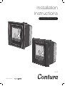
Installation
Instructions
For use in GB and IE only
C i4
www.contura.eu
GB
82
CERTIFICATE
DECLARATION OF PERFORMANCE
No. Ci4-CPR-130619-SE-1
PRODUCT
Product type
Type designation
Manufacturing number
Intended area of use
Fuel
MANUFACTURER
Name
Address
CHECKS
According to AVCP
European standard
Test institute
Insert lit with solid biofuels
Contura i4
See rating plate on the insert
Heating of rooms in residential buildings
Wood / (Coal briquettes)
NIBE AB / Contura
Box 134, Skulptörvägen 10
SE-285 23 Markaryd, Sweden
System 3
EN 13229:2001 / A2:2004
Rein-Ruhr Feuerstätten Prüfstelle, NB 1625,
has checked declared performance and issued test report no. RRF-29 11 2751
DECLARED PERFORMANCE
Essential characteristics
Performance
Harmonised technical
specification
Reaction to fire
A1 WT
Minimum distance to combustible material
150 mm to rear
150 mm to side
According to the given conditions in the installation instructions
Risk of falling embers
Approved
Emissions from combustion
Wood / (Coal briquettes)
CO
NOx
OGC
PM
0.10% /
(0.21%)
108 mg/m3 / (NPD)
107 mg/m3 / (NPD)
36 mg/m3 / (10 mg/m3 )
Surface temperatures
Approved
Cleaning options
Approved
Mechanical durability
Approved
Emissions of hazardous substances
Approved
Nominal output
4 kW
/
(4 kW)
Efficiency
78%
/
(76%)
Flue gas temperature in connector at nominal
output
310°C
/
(270°C)
The undersigned is responsible for the manufacture and conformity with the declared performance.
Niklas Gunnarsson, Business area manager NIBE STOVES
Markaryd, 1st July 2013
EN 13229:2001 / A2:2004
GB
CONTENTS
A warm welcome to Contura.
A warm welcome to the Contura family. We hope
you will get a great deal of pleasure from your new
stove. As a new owner of a Contura stove you have
secured a product with timeless design and long
service life. Contura also has combustion that is both
environmentally friendly and efficient for the best heat
production.
Read through these installation instructions carefully
before installation. Read how to best light your stove in
the lighting instructions.
Table of contents
Technical data
84
Dimensions85
Recessing the insert
86
Recess example
87
Installation in Builders opening
88
Supply of combustion air
88
Prior to installation
89
Installing and connecting the convection box
90
Smoke control area
93
Installing stove body into the convection box
94
Installing fire box insulation panels
96
NOTE!
WARNING!
Report the installation of a stove to
your local authority.
The stove becomes very hot.
The owner of the house is personally responsible
for ensuring compliance with the mandatory safety
requirements and must have the installation approved by
a qualified inspector. Your local chimney sweep must also
be informed about the installation as this will affect the
routines for regular chimney-sweeping services.
During operation, certain surfaces of the stove become
very hot and can cause burn injury if touched. Be aware
of the strong heat radiated through the hatch glass.
Placing flammable material closer than the safe distance
indicated may cause a fire. Smouldering can cause quick
gas ignition with the risk of damage to property and
personal injury.
83
GB
84
FACTS
Technical data
Output
3-5 kW
Nominal output 4 kW
Efficiency level Up to 78%
ModelClassic
Weight (kg)
77
Width (mm)
490
Depth (mm)
420
Height (mm)
600
Model
Weight (kg)
Width (mm)
Depth (mm)
Height (mm)
Modern-3-sided frame
71
490
380
590
Model
Weight (kg)
Width (mm)
Depth (mm)
Height (mm)
Modern-4-sided frame
72
490
380
635
The connector’s inner diameter is Ø126 mm
Type approved in accordance with:
European standard EN-13 229
(DE/A) DINplus, Art. 15a B-VG
RRF-29 11 2751
DEFRA exempted
The stove can be used in Smoke Control
Areas.
General
Chimney
In this manual you will find instructions
about how your Contura i4 shall be
installed. Before you start the installation
it is important that you read this
instruction carefully and fully understand
the requirements. All European, national
and local standards and regulations needs
to be fulfilled when the appliance are
installed.
To guarantee the function and safety of
the stove we recommend that it is installed
by a professional. Our Contura agents can
recommend a suitable installer.
Note! The stove installation and connection
to a chimney must be accomplished with
the current edition of Building Regulations.
We recommend that you consult a local
chimney sweep before the installation
to make sure that the chimney is in good
condition.
The stove is type approved and must be
connected to a chimney dimensioned
for at least 350°C. The connector on
the appliance is suitable for pipes with
diameter of 125 mm.
The room or space containing a stove shall
have a permanent air supply sufficent to
ensure proper combustion, to determine
correct amount of air supply use current
edition of Building Regulations.
Remember to use only for the appliance
recommended fuel as wood logs
or smokeless fuel as anthracite or
manufactured smokeless fuel briquettes.
Do not ever burn bituminous coal, “petrocoke” or other petroleum based fuels!
Building application
Before installing a stove or erecting a
chimney it is necessary for you to apply
for planning permission from your local
authority. Ask your local authority for
advice regarding building regulations and
the application.
A flexible flue liner or steel flue
certified for use with solid fuel is highly
recommended. The stove requires a
draught in the chimney of at least –12
Pa. The draught is affected both by the
length and area of the chimney, and by how
well sealed it is. Minimum recommended
chimney length is 3.5 m and a suitable
cross section area is 120-175 cm² (125150 mm in diameter). Carefully check that
the chimney is sealed and that there is
no leakage around soot hatches and flue
connections.
Note that a flue with sharp bends and
horizontal routing reduces the draught in
the chimney. Maximum horizontal flue is 1
m, on the condition that the vertical flue
length is at least 5 m. It must be possible
to sweep the full length of the flue and the
soot hatches must be easily accessible.
Secondary air
inlet control
Convection box
Handle
(removable on modern)
Fire-box insulation panels
Log guard
Grate
Primary air
inlet control
WOOD
COAL
Ash-pan
Type plate
GB
Dimensions
Dimensions
Ci4
Ci4 Classic
300
Flue outlet 45° backwards
420
350
45°
580
530
40
60
550
600
390
40
255
50
300
490
Ci4 Modern 3 - sided frame
Flue outlet 45° backwards
415
350
380
300
45°
530
580
40
60
550
590
390
300
40
255
45
490
Ci4 Modern 4 - sided frame
300
45°
530
580
60
45
635
550
40
40
255
45
490
415
350
380
390
300
Flue outlet 45° backwards
85
GB
86
RECESSING THE INSERT
Recessing the insert
When recessing the insert, adjacent walls that are not classed as fire walls or are considered unsuitable for heat loads must be protected
by non-combustible material according to the specification below.
All joints on the non-combustible material must be sealed using the manufacture’s recommended method. The area between the insert
and the recess must be ventilated according to the specification/dimension.
When top connecting a steel flue please refer to the relevant manufacturer’s installation instructions. Observe the safety distances to
combustible material that steel flues require. Heat radiation from the hatch is strong and is why combustible material must not be placed
closer than 1 m in front of the hatch. When recessing, building material must not be in direct contact with the insert due to the thermal
expansion of the insert.
Material requirements
The building material must not be combustible.
The thermal conductivity coefficient λ may be a maximum of 0.14 W/mK.
The thickness of the building material must always be at least 100 mm.
In cases where the building material’s insulation properties are given as a U-Value, this must be a maximum of 1.4 W/ m²K.
List of suitable materials:
Aerated concrete: λ =0.12-0.14
λ =0.12-0.14
Vermiculite: Calcium silicate: λ =0,09
Heat shield
If the recess is to extend to the ceiling, a heat shield must be made above the convection exhaust. This is to prevent hot air collecting in
the recess closest to the ceiling. The seal must a maximum of 100 mm above the convection exhaust’s upper edge and must be made up
of 20 mm thick building boards made of calcium silicate or a panel with at least a 50 mm thickness of rock wool on top.
Convection air
The convection air ventilates the surround, cools the insert and transports the hot air out into the room. The total sum of the effective
cross section area up and down must not be less than the stated values. The air intake must be positioned somewhere between the floor
and the bottom of the insert, up to or on the sides of the recess. The vent must be positioned above the insert’s highest point up to or to
the sides of the recess.
Observe the minimum distance up to the ceiling.
Convection air in: 200 cm²
Convection air out: 200 cm²
Note that building regulations apply regarding the area below and in front of the insert, see section ”Hearth plate” below.
Load bearing base
Ensure that the bottom of the convection box is installed on a loadbearing with the strength to support the weight of the insert and the
chimney. The insert can be loaded maximum 100 kg of chimney. The load bearing must not prevent the convection air ventilate the area
between the insert and recsess.
Hearth plate
Due to the risk of falling embers, a flammable floor must be protected by a hearth plate. It must extend 300 mm in front of the stove
and 100 mm on each side of the stove, or have a 200 mm extension on each side of the opening. The hearth plate can consist of natural
stone, concrete, metal plate or glass, consult the Building regulations.
10
GB
RECESS EXAmPLE
100
100
50
50
100
100
50
The dimensions are the
minimum dimensions,
unless otherwise stated.
50
500
!
Wall of combustible material
600
20
Wall of non-combustible material, made
of 100 mm aerated concrete in the recess
example.
300
800
100
Wall of non-combustible material that is
not in contact with combustible material
and therefore has no minimum thickness
requirement.
800
100
20
max 100
50
500
20
Heat shield
50
100
Area out min. 200 cm2
500
300
100
300
50
100
Ci4 Classic and Modern
100
100
Ci4
20
100
Recess example
Area in min. 200 cm2
50
100
Load bearing base
87
GB
INSTALLATION / COMBUSTION AIR
Installation in Builders opening
Hearth dimensions
The appliance must stand on a constructional hearth which meet
the building regulations and has minimum dimension as shown in
the diagram beside. Always check that the building has enough
bearing capacity for the heart, stove and chimney. The stove can
be loaded with maximum 100 kg of chimney.
150 m
m
450 mm
790
150 m
m
mm
125 mm
88
Supply of combustion air
When a stove is installed in a room, the demand for air supply to
the room increases. Air can be provided indirectly via a vent in the
outer wall or via a duct from the outside that is connected to the
stove. The amount of air needed for combustion is approximatly
20m³/h.
If the insert will be used with supply air connector (accessory)
and outside air-supply kit (accessory) then prepare the convection
box by open the lid where the air supply hose will enter, from side
or back. Make the supply air connector installation as the flue pipe
is connected to the convection box.
Supply air connector (accessory)
Outside air-supply kit (accessory)
GB
PREINSTALLATION
Prior to installation
Remove loose components as stove base plate and ash tray. Take
out the stove body from the convection box by first unscrew the
four side bolts and the four bolts for the collar. At last release the
convection box from the pallet.
!
LEK
10
UM
DI
NA
VA
.7
No
10
1
3
x4
2
x4
4
E
M
RO
CH
89
GB
90
INSTALLING AND CONNECTING
Installing and connecting the convection box
Flue collar 90° straight upwards or 45° backwards
If the builders opening is too tight above when the flue collar adapter
plate is turned for installation 45° backwards, then remove and fasten
the flue collar adapter on the flue. Install the convection box and finally
fasten the flue adapter on the convection box, see “Flue collar 45°
backwards and tight builders opening” on side 92.
1a
Straight upwards
1b
2
45° backwards
180°
GB
INSTALLING AND CONNECTING
3
4
13
No.
7
CHRO
ME
VAN
ADI
UM
13
LE
K
Ø 6 mm
5
6
91
GB
92
INSTALLING AND CONNECTING
Flue collar 45° backwards and tight builders opening
1
2
3
4
LE
K
Ø 5 mm
5
6
GB
SmOKE CONTROL AREA
Smoke control area
In smoke control areas it is mandatory to stop the damper from
closing completely. In other areas it´s optional.
1
2
93
GB
94
INSTALLING STOVE BODY
Installing stove body into the convection box
1
2
x4
!
3
!
Classic - fasten the screws properly after the
stovebody is fitted to the backpanel
Modern - fasten the screws only a few turns,
they shall be fasten properly first when
the cast iron frame are assembled and fitted,
see side 95
x4
LEK
10
UM
DI
NA
VA
No
10
4
x4
CH
E
M
RO
.7
GB
INSTALLING STOVE BODY
Modern frame
1
2
3
4
13
13
o.
N
7
7
O
o.
R
N
C
H
E
C
M
R
O
H
UM
E
DI
M
NA
VA
M
IU
N
AD
VA
13
13
!
Make sure that the stovebody
and frame are parallel before
fasten the screws
95
GB
96
INSTALLING FIRE PANELS
Installing fire box insulation panels
The Thermotte insulation panels are fragile, handle them with care and
be careful when placing them into the stovebody.
1
2
GB
INSTALLING FIRE PANELS
3
4
!
5
Final inspection of the installation
It is very important that the installation is inspected by an authorised chimney sweep before the
stove is used. Also read the ”Operating instructions”, before lighting for the first time.
97
NIBE AB · Box 134 · 285 23 Markaryd · Sweden
www.contura.eu
811163 IAV Ci4 SE_EX-5
2014-02-10
Contura reserves the right to change dimensions and
procedures described in these instructions at any
time without special notice. The current edition can be
downloaded from www.contura.eu