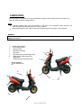
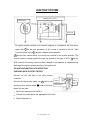
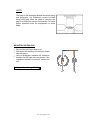
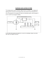
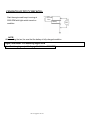
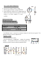
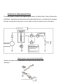
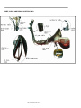
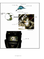
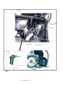
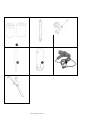
1
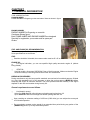
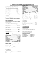
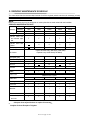
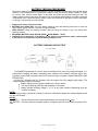
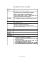
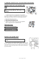
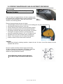
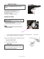
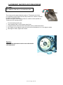
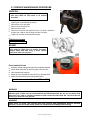
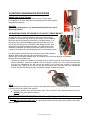
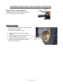
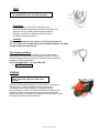
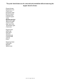
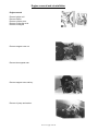
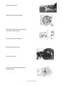
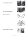
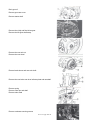
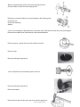
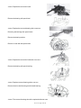
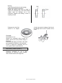
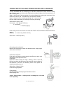
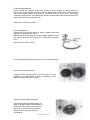
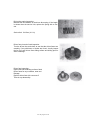
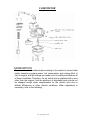
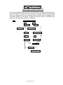
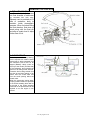
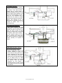
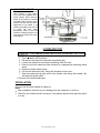
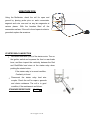
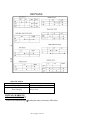
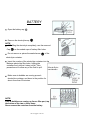
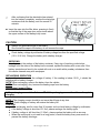
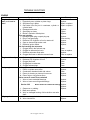
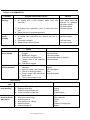
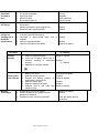
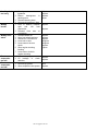
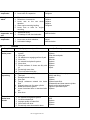
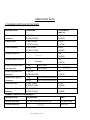
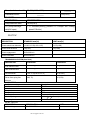
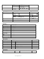
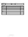
Service Manual
Table of Contents
Rev.
1
Date
01/05/2004
Chapter
1. General Information.........................Page 1
2. Periodic maintance and service.......Page 4
3. Engine..............................................Page 23
4. Fuel and Lubrication System...........Page 37
5. Electrical System.............................Page 48
6. Servicing Information........................Page 62
This service manual has been specially prepared to provide all the necessary information for the
proper maintenance and servicing of VENTO Zip r3i Scooter.
This manual contains an introductory description on VENTO Zip r3i and procedures for
Inspection/Service and overhaul of its main components. This Manual is intended those who have
enough knowledge and skills for servicing of VENTO vehicles. Without such knowledge and skills
you should not attempt servicing by relying on this manual only. Instead, please contact your nearly
authorized VENTO motorcycle dealer.
CHAPTER 1
1-1 GENERAL INFORMATION
TYPE & IDENTIFICATION
FRAME NUMBER
FRAME NUMBER is Engraving on the steel tube of frame as shown in figure.
ENGINE NUMBER
ENGINE NUMBER is Engraving on rear side
Crankcase Shown figure.
Both FRAME NUBER AND ENGINE NUMBER are designed
Specially for registration your scooter and for spare part
Orders.
FUEL AND ENGINE OIL RECOMMENDATION
Be sure to use specified fuel and engine oil.
Some specifications are as follows:
FUEL
Gasoline should be Unleaded, the octane number must be 85 ~95 or more.
ENGINE OIL
For engine lubrication, you can use specified high quality two-stroke engine oil (without
being diluted).
GEAR OIL
Use high quality, all-purpose SAE10W/40 Gear oil for this scooter. Make sure that the Engine
oil/Gear oil what you are using should come under API classification.
BREAK-IN PROCEDURES
During manufacture only the best possible materials are used and all machined parts are finished
to a very high standard but it is still necessary to allow the moving parts to BREK-IN before
subjecting the engine to maximum stresses. The future performance and reliability of the engine
depends on the care and restraint during its early life.
General requirements are as follows
Limit break-in speed
At the first 1000 ms (630 miles mileage use throttle opening less than 1/2.
Up to 1600 Kms 1000 miles mileage use throttle opening less than 3/4.
Upon reaching an odometer reading of 1600 kms (1000 miles) you can subject the motorcycle
to full throttle operation.
Do not maintain constant engine speed for on extended time period during any portion of the
BREAK-IN period, try to vary the throttle position.
1-2 GENERAL INFORMATION
PRECAUTIONS AND GENERAL INSTRUCTIONS
GENERAL PRECAUTIONS:
WARNING
Proper service and repair procedures are important for the safety of the service mechanic and the
reliability of the vehicle.
When two or more persons are working together, pay attention to the safety of each other.
When it is necessary to run the engine indoors, make sure that the exhaust gas is forced outwards
and ventilation should be proper.
When working with toxic or flammable materials, make sure that the area you work in is well
ventilated and that you follow all off the material manufacturer s instructions.
Don t use gasoline as a cleaning agent.
After servicing the motorcycle check all lines i.e. fuel, oil and brake lines for leaks.
Whenever you remove Oil seals, Gaskets, packing, O-rings, Locking washers, Cotter pins, Circlips,
and certain other parts as specified, are sure to replace them with ones. Also before installing these
new parts be sure to remove any left out material from the mating surfaces.
Never reuse a circlip, when installing a new circlip, take care not to expand the end gap larger than
required to slip the circlip the shaft. After installing a circlip, always ensure that it is completely
seated in its groove and securely fitted.
Do not use self- locking nuts a few times over.
If parts replacement is necessary, replace the parts with VENTO Genuine parts or their equivalent.
When removing parts that are to be reused, keep them arranged in an orderly manner so that they
may be reinstall in proper order and orientation.
Always use special tools when required.
Always use specified lubricant, bond& sealant.
While removing the battery, disconnect the Negative terminal / Cable first then Positive terminal /
Cable and when reconnecting the battery, connect the Positive terminal / Cable first then
Negative terminal / Cable.
During Service to electrical parts, if no need of battery power then, please disconnect the Negative
terminal / Cable of the battery.
During tightening of Cylinder head and crank case bolts and nuts start with larger diameter and
ending with smaller diameter, from inside to outside diagonally, with the specified tightening torque
values.
After reassembly, recheck parts for tightness and operation.
REPLACEMENT COMPONENTS
Be sure to use genuine VENTO spare parts or their equivalent. Genuine VENTO components are high
quality parts, which are designed specially for VENTO vehicles.
CAUTION
Scooter/motorcycle may damage by using non genuine parts or parts that is not equivalent to
VENTO parts and will be affecting performance also.
1-3 GENERAL INFORMATION SPECIFICATIONS
DIMENSIONS AND NET WEIGHT
Overall Length.......................1620mm
Overall Width...........................625mm
Overall Height.......................1010 mm
Wheelbase.............................1170mm
Ground Clearance......................90mm
Dead Weight................................78kg
CHASSIS
Front shock absorber
Telescopic, Coil spring, without oil damped.
Ignition Timing......................150 at 5000 RPM
Spark Plug.........................NGK/R/BR8HSA
Storage Battery....................YUASA/YB4L-4
Battery Capacity.............................12V-4Ah
Magneto..................................................AC
Fuse..................................................10Amp
Headlight............................12V 35 / 35 Watt
Turn Indicators (X4)...................12V / 3
Watt
Tail light/stop light.......................12V /
5Watt
Meter light..................................12V / 3Watt
Oil level Indicator light...............12V / 3 Watt
Tran signal Indicator light...........12V / 3Watt
High beam Indicator light............12V/3 Watt
Rear shock absorber
Swing arm type Coil spring, with oil damped.
CAPACITY
Steering angle
48º (toward the left\toward the right)
Fuel Tank........................................5.2L
Engine Lubricating Oil Tank............1.0L
Gear Oil...........................................0.1L
Front Tire size................................3.50-10
Rear Tire size.................................3.50-10
Front brake Disc................................. 160
Rear brake Drum................................ 110
ENGINE
Type.....................Two-stroke, Air Cooled
Intake system.........................Reed valve
No. of Cylinder........................................1
Bore.............................................40.0mm
Stroke..........................................39.6mm
Displacement........................................49.8CC
Compression Ratio............................6.9:1
Carburetor.................................Side draft
Air cleaner..........Dual polyurethane foam
Starting System
Electric start & Kick pedal for Manual Start.
Lubricating System
Auto lubrication, by Oil Pump
ELECTRICAL
Ignition
CDI
System.......................Electronic
TRANSMISSION
Clutch System
Dry shoe, Automatic, Centrifugal Type
Gears shifting mechanism
Automatic Primary Reduction 1
Gear Reduction ratio
The first gear...................3.692(48/13)
The second gear.............3.000(36/12)
Drive System...................V-Belt driv
CHAPTER 2
PERIODIC MAINTENANCE AND SERVICE
Contents
Periodic maintenance and service schedule................................5
Storage battery.............................................................................7
Service and adjustment procedures.............................................9
Cylinder head nut and exhaust pipe bolt .....................................9
Cylinder head and cylinder ..........................................................9
Spark plug ...................................................................................10
Air cleaner....................................................................................11
Fuel level line...............................................................................12
Throttle cable...............................................................................12
Engine idle speed.........................................................................12
Oil pump.......................................................................................13
Gear oil.........................................................................................14
Braking..........................................................................................15
Tire................................................................................................17
Steering ........................................................................................17
Front shock absorber ...................................................................18
Rear shock absorber ....................................................................18
Vehicle bolts and nuts ...................................................................18
Rev no.01/ page 6of 128
2-1 PERIODIC MAINTENANCE SCHEDULE
The chart below lists the recommended intervals for all the required periodic service work necessary to keep
the motorcycle operating at peak performance and economy. Mileages are expressed in terms of Kilometer,
Miles and time for your convenience.
Note:
More frequent servicing may be performed on motorcycles that are used under bad road condition.
PERIODIC MAINTENANCE CHART
Miles
630
3780
7560
11340
15120
Interval
Kilometer
1000
6000
12000
18000
24000
Months.
2
I
12
I
24
I
36
I
48
I
T
T
T
T
T
C
C
C
C
C
R
C
R
Storage battery
Cylinder head nut
and exhaust pipe
bolt
Cylinder head and
cylinder
Spark plug
Inspect & Clean every 3000 Kms (1890 miles)
Air cleaner
Replace every 12000 Kms(1750 Miles)
Idle speed (rpm)
I
I
I
I
I
Throttle cable play
I
I
I
I
I
Oil pump
I
I
I
I
I
Gear oil
I
I
I
R
I
I
I
I
I
I
I
Steering
I
I
Replace every 4 years
I
I
Replace every 4 years
I
Replace every 2 years
I
Front fork
I
I
absorber
I
Tire
Fuel line
Brake
Brake hose
Brake fluid
Rear
R
I
I
I
I
I
I
I
I
I
I
I
I
I
I
I
I
I
I
I
I
I
I
T
T
T
T
T
shock
Vehicle body bolts
and nuts
Note:
I=inspect clean adjust lubricate or replace if necessary
A=adjust C=clean R=replace T=tighten
Rev no.01/ page 7of 128
2-2 PERIODIC MAINTENANCE PROCEDURE
BATTERY INSPECTION AND CHECKING PROCEDURE
Storage Battery
Inspect at initially 1000Kms 630 miles 2
months and every 6000 Kms 3780 miles 12
months.
Open seat, and then remove the battery box cap in
theMiddle of helmet box.
Disconnect Negative terminal / Cable first then Positive terminal / Cable of Battery.
Measure the voltage between the +ve and ve terminal of Battery charge the Battery if the
voltage is below the specified limit.
Rev no.01/ page 8of 128
BATTERY TESTING PROCEDURE
Remove the battery from the Motorcycle/Scooter. Connect the battery on load tester ensuring Red lead of
tester to (+ve) and Black lead to (-ve) terminal of battery. Check the terminal voltage of battery. It should
be 12~14.5 Volts. Press the push button on the tester and watch the voltmeter reading on load. The
battery voltage should not drop down less than 9 volts; this indicates that the battery is perfect to take load
of self-starter motor. Check the specific gravity of each cell should not be less than 1.220.Put the battery
on charge, if required and carry out load test.
Diagnose the nature of failure as under:
BATTERY CELL DEAD TEST: On load if battery voltage is found less than 9.5Volt and one or more cell
shows specific gravity less than 1.220 then change the battery.
OPEN CIRCUIT: During the charging of battery does not pickup the charge. In any of the above case,
replace the battery.
RECOMDED BATTERY LOAD TESTER: MAKE ELAK, MODEL: ---BCT7
CAUTION: During Inspection, if the battery on the vehicle is found defective, before replacing with
a new battery, it is important to check the battery charging circuit.
BATTERY CHARGING CIRCUIT TEST
The MAGNETO generated AC current, which is rectified into DC current by Voltage Regulator .It, is
automatically charging the battery depending upon condition of the battery, load and engine rpm.
Regulator is connected in parallel to the circuit. Hence this type of system is called PARALLEL LOAD
REGULATOR .
Connect DC Voltmeter and DC Ammeter, start the engine with fully charged good battery. The
Voltage Regulator output is as follows.
Battery charging current range in between 0.6 Amp to 2Amp.
The engine speed @ 5000 rpm with headlamp on condition.
Battery terminal charging voltage > 11.5 V at any load condition (depending upon the
condition of battery)
NOTE 1
Incase charging output is less than 0.6 Amp or more than 2.0Amp then replace the Voltage Regulator with
new one and recheck.
NOTE 2
AMMETER: ------Series connection inline with positive battery wire to measure DC Amp.
VOLTMETER: ---Parallel connection between positive & negative terminal of the battery to measure DCVolts.
Rev no.01/ page 9of 128
IMPORTANT TIPS ON BATTERY
SPECIFIC
GRAVITY
WARNING
CHARGING
The Specific Gravity of fully charged battery should be 1.220~1.240
Use Hydrometer to check each cell of battery.
Remove negative terminal first, then positive terminal.
If the battery is corroded by sulfur. Please exchange it. If the terminal
of the battery has too much precipitate, please exchange it.
Charging is necessary at less than 1.220 Specific Gravity for old
battery. It changes according to electrolyte temperature.
Connect positive terminal of charger to positive battery wire &
negative terminal of charger to negative battery wire.
CHARGING
CURREENT
For 2.5 Ah battery the charging current should be Maximum 0.25Amp.
For 6.0 Ah battery the charging current should be Maximum 0.6Amp.
CHARGING TIME
For new battery 8-12 hrs.
For old battery 12-14 hrs.
Always open all the caps of battery before charging.
Keep flames & sparks away from the battery.
Turn ON or OFF Switch at charger & not at battery terminal
Don t charge the battery, if electrolyte temperature is more than 45ºC.
Do not quick charge the battery.
WARNING
INSTALLATION
BATTERY
CAPACITY
RECOMMENDED
BATTERY
CHARGER
RECOMMENDED
HYDROMETER
NOTE
Connect positive terminal first, then negative terminal.
12Volt- 6Ah YTX7A-BS/YUASA
Make: ELAK
Model C1/48
Make: THIMSON
Model: 108
Always top up battery with the distilled water up to the maximum
level (Never use Acid to top up the old battery).
Always ensure new battery is being charged in cold condition after
filling with the electrolyte.
Always ensure that battery breather tube is not clogged, crimped
or bent. Breather tube should be properly routed.
Incase if Motorcycle/ Scooter is not being used for longer
period, then first charge the battery fully & then connect only
positive terminal to Motorcycle /
Rev no.01/ page 10of 128
2-3 PERIODIC MAINTENANCE AND ADJUSTMENT PROCEDURE
Cylinder head nuts and exhaust pipe
bolts
Tighten at Initially 1000 km 630 miles or 2
Months and every 6000 km 3780 miles or 12
months.
If cylinder head nuts are not tightened to the specified torque,
may result in leakage of compressed fuel-air mixture and reduce
output, tighten the cylinder head nuts in the following procedures:
1.
2.
3.
4.
Remove the frame lower covers.
Remove the cylinder head cover bolt.
Remove spark plug Suppressor cap.
Tighten the nuts evenly one by one to the specified
torque. Tighten the nuts in the Specified order.
Tightening Torque
Cylinder head nut 15-18N.m
Exhaust pipe bolt 15-18N.m
Cylinder and cylinder head
carbon
Remove carbon every 6000 km 3780 miles or 12
months.
Carbon deposits in the combustion chamber and the cylinder head will
raise the compression ratio and may cause preignition and overheating.
Carbon deposition at the exhaust port of the cylinder will prevent the flow of
exhaust gases, reducing the output. Remove carbon deposits periodically as
per specified schedule.
Rev no.01/ page 11of 128
2-4 PERIODIC MAINTENANCE AND ADJUSTMENTS PROCEDURE
SPARK PLUG
Neglecting the spark plug maintenance eventually leads to difficult
starting and poor performance. If the spark plug is used for a long
time, the electrode gradually burns away and carbon builds up
along the inside part. In accordance with the periodic table, the plug
should be removed for inspection, cleaning and to reset the gap.
Carbon deposits on the spark plug will prevent good sparking and cause
misfiring. Clean the carbon deposits periodically.
CARBON DEPOSIT
Check to see the carbon deposit on the Spark Plug. If the carbon is
deposited, remove it with a spark plug cleaner machine or carefully
using a tool with a pointed end.
Check to see the worn out or burnt condition of the electrodes. If it
is extremely worn or burnt, replace the plug and also replace the
plug if it has a broken insulator, damaged thread etc.
Thickness gauge
Spark plug gap 0.6~0.7 mm (0.024-0.028 inch)
Check the spark plug for burnt condition. If abnormal replace the
Tighten the spark plug to the specified torque.
Spark Plug
Tightening torque: 15-18 N.m
NOTE:
To check the spark plug, first make sure that the fuel
used is unleaded gasoline.
Confirm the Specification thread send and reach while
replacing the spark plug.
Rev no.01/ page 12of 128
2-5 PERIODIC MAINTENANCE AND ADJUSTMENT PROCEDURE
AIR CLEANER:
Clean every 3000 Kms 1890 miles Replace every
12000 Kms(1750 Miles)
If the air cleaner is clogged with dust, Air Intake resistance will
be increased with a result decrease in power output and will be
increase in fuel consumption. Check and clean the filter
element in the following manner.
Remove clamp and screw take out air cleaner
Unscrew tapping screw remove air cleaner cover washing pan of a proper size with Fill a
Non-flammable cleaning solvent. Put the air
Cleaner element in the cleaning solvent and wash properly.
Squeeze the cleaning solvent out of the washed element
By pressing it between the palms of both hands: do not twist
Or wring the air cleaner element or it will develop tears.
Immerse cleaned filter element in CCI or CCI Super oil and
Squeeze the oil out of the element leaving it slightly wet
With oil. Fit the element to the Air cleaner case properly
Install Air cleaner in the reverse order of removal.
CAUTION
Before and during the cleaning operation, inspect the core for tears. A torn filter element must be
replaced with new one.
Be sure to position the filter element snugly and correctly
So that no incoming air will bypass it. \Remember, rapid wear
of piston rings and cylinder bore is often caused by a
defective or poorly fitted filter element.
- Non-flammable cleaning solvent (Kerosene)
- CCI OR CCI Super oil or SAE 80 or90 Gear oil.
Rev no.01/ page 13of 128
THROTTLE CABLE
Adjust at initially 1000Kms 630 miles or after 2 months.
And after every 6000 Kms 3780 miles or after 12
months.
Loosen locknut and adjust throttle cable play by
turning adjuster in or out to obtain the
following cable play. After adjusting the cable
Play tightens the locknut.
Cable plays 0.5-1.0MM 0.02.-0.040 inch
ENGINE IDLE SPEED
Adjust at initially 1000Kms 630 miles or after 2
months and Every 6000 kms (3780 miles or after 12
months thereafter.
Adjust the throttle cable play.
warm up the engine at normal running condition
NOTE:
A warm engine means an engine that has been
run for 10 minutes.
@
Connect an Digital Tachometer to the connecting portion of the magneto lead
In the illustration. Use the selector key C position.
Adjust the Idling Screw @ to obtain the Idling RPM as follows:
Idling Speed 1800±100 RPM
Finally adjust the throttle cable play.
FUEL LINE
Inspect at initially 1000 km 630 miles or after 2
months) and Every 6000 km (3780 miles or after12
months), replace after every 4 years.
Rev no.01/ page 14of 128
wire as shown
2-6 PERIODIC MAINTENANCE PROCEDURE
OIL PUMP:
Inspect at Initially 1000 Kms 630 miles 2 months and
every 6000 kms 3780 miles or 12 months there after.
The oil pump to the engine feeds the engine oil. The amount of oil fed to
it is regulated by engine speed and oil pump control lever, which is controlled
by amount of throttle opening.
Check the oil pump in the following manner to confirm correct operation for
Throttle valve full opening position.
Turn the throttle grip full open.
Check whether mark on the oil pump control lever
Is aligned with the index mark when the throttle valve is positioned as above.
If the marks are not aligned, loosen lock nuts and turn the adjuster in or out to align the marks.
After align the marks, tighten the locknuts.
Caution
Oil pump cable adjustment must be done after throttle
cable adjustment.
Rev no.01/ page 15of 128
2-7 PERIODIC MAINTENANCE PROCEDURE
GEAR OIL:
Inspect at initially 1000 km 600 miles or 2 months
and every 6000 km 3780 miles or 12 months
thereafter.
Inspect gear oil periodically as follows:
Remove the cover and hose.
Remove the kick-start lever.
Remove clutch cover
Remove oil level bolt and inspect oil level, if oil level is below the
oil hole level, Add oil until oil flows from the level hole.
Tighten oil level bolt to the specified torque.
Tightening torque
9-15N.m(0.9-1.5 kg-m)
BRAKE:
Inspect at initially 1000 km 600 miles 2 months and
every 6000 km 4000 miles 12 months thereafter,
replace brake fluid after every 2 years, replace
brake hose after every 4 years.
Front brake fluid level
Keep the scooter upright and place the handlebar straight.
Check brake fluid level by observing the lower limit line
On the brake fluid reservoir.
When the level is below the lower limit line, replenish with
Brake fluid that meets the following specification.
Specification and classification DOT 3 or DOT4
WARNING
The brake system of this scooter is filled with a glycol-based brake fluid. Do not use or mix
different types of fluid such as silicone-based and petroleum-based. Do not use any brake fluid
taken from old, used or unsealed containers. Never re-use the brake fluid left over from the last
servicing or stored for long periods.
WARNING
Brake fluid, if it leaks, will interfere with safe running and immediately discolor painted
surfaces. Check the brake hoses joints for cracks and oil leakage before riding.
Rev no.01/ page 16of 128
2-8 PERIODIC MAINTENANCE PROCEDURE
BRAKE PADS (FRONT BRAKE)
Observing the limit can check the Wear condition of brake pads
Line marked on the pad. When the wear exceeds the limit mark, replace
the pads with new ones.
CAUTION:
Replace the brake pad as a set, otherwise braking efficiency will be
Adversely affected.
AIR BLEEDING FORM THE BRAKE FLUID CIRCUIT (FRONT BRAKE)
Air trapped in the fluid circuit acts like a cushion to absorb a large
proportion of the pressure developed by the master cylinder and thus
interferes with the full braking performance of the brake caliper. The
presence of air is indicated by sponginess of the brake lever and
also by lack of braking force. Considering the danger to which such
trapped air exposes the machine and rider, it is essential that, after
remounting the brake and restoring the brake system to the normal
condition, the brake fluid circuit be purged of air in the following manner:
Fill up the master cylinder reservoir to the upper end of the inspection
Window. Replace the reservoir cap to prevent entry of dirt.
Attach a pipe to the caliper bleeder valve, and insert the free end of the pipe into a receptacle.
Bleed air from the bleeder valve.
Squeeze and release the brake lever several times in rapid succession. And squeeze the lever fully
without releasing it. Loosen the bleeder valve by turning it a quarter of a turn so that the brake fluid
runs into the receptacles: this will remove the tension of the brake lever causing it to touch the
handlebar grip. Then, close the valve, pump and squeeze the lever, and open the valve. Repeat this
process until the fluid flowing into the receptacle no longer contains air bubbles.
NOTE
When bleeding the braking system, replenish the brake fluid reservoir if necessary. Make sure that there
is always some fluid visible in the reservoir.
Close the bleeder valve, disconnect the pipe. Fill the reservoir with specified brake fluid to the
UPPER end of the inspection window.
TIGHTENING TORQUE BLEEDER VALVE: 6-9N.m (0.6-0.9kg-m, 4.5-6.5lb-ft)
CAUTION
Handle brake fluid with care: The brake fluid reacts chemically with paint, plastics, and rubber
materials, etc.
Rev no.01/ page 17of 128
2-9 PERIODIC MAINTENANCE AND ADJUSTMENT PROCEDURE:
BRAKELEVR PLAY (REAR BRAKE):
Turn adjusting nut 2 so that the play @ of Brake
Lever is 15-25mm (0.6~0.8) as shown.
BRAKE SHOE WEAR:
This vehicle is equipped with the brake lining limit
Indicator on the rear brake.
Inspect brake lining limit as follows:
First check if the brake system is properly
Adjusted.
When operating the brake, check to see that
the tip of indicator is within the range.
If the tip of indicator is beyond the range,
the brake shoe assembly should be replaced
with a new set of shoes.
3
4
Rev no.01/ page 18of 128
TIRE
Inspect at initially 1000Kms 630 miles 2 months and
every 6000KM 3780 miles 12 months thereafter
Tire pressure
If the tire pressure is too high, the steering will be
Adversely affected and tire wear increased. Conversely, if tire
pressure is too low, stability will be adversely affected.
Therefore, maintain the correct tire pressure for good
Drivability and to prolong tire life.
CAUTION:
The standard tire fitted on the scooter is 3.50-10 for front and rear
The use of other Than standard may cause handling instability. It is highly
recommended to use genuine tire.
Tire treads condition
Operating the scooter with the excessively worn tires will decrease
riding stability and consequently invite dangerous situation. It is highly
Recommended to replace the tire when the remaining depth of tire tread
reaches the following specification.
Tire Tread depth limit: 1.6 mm 0.064 Inch
Use Tire depth gauge
STEERING
Inspect at initially 1000 kms 630 miles 2
months and every 6000 kms (3780 miles)
thereafter.
Steering should be adjusted properly for smooth turning of handlebars
and safe running. Over tight steering prevents smooth turning
of handlebars and too loose steering will cause poor stability.
Check that there is no play in the front fork assembly by supporting the
machine so that the front wheel is off the ground, with wheel straight
ahead, grasp lower shock absorber near the axle and pull forward. If play is
found, perform steering bearing adjustment.
Rev no.01/ page 19of 128
FRONT FORK:
Inspect &Adjust at initially 1000 kms 630 miles 2
months and every 6000 km 3780 miles 12 months
thereafter.
Inspect the front shock absorber for oil leakage or other damage, and replace the defective parts, if
necessary.
REAR SHOCK ABSORBER:
Inspect &Adjust at initially 1000 kms 630 miles 2
months and every 6000 km 3780 miles 12 months
thereafter.
Inspect the rear shock absorber for oil leakage and mounting rubbers including engine mounting for wear
and damage, and replace the defective parts, if necessary.
CHASSIS BOLTS AND NUTS:
Inspect &Adjust at initially 1000 kms 630 miles 2
months and every 6000 km 3780 miles 12 months
thereafter.
These bolts and nuts listed below are important safety components. They must be
tightened to the specified torque.
No.
Item
Nm
Kg-m
1
Front axle nut
37-44
3.7-4.4
2
Steering stem locknut
37-44
3.7-4.4
3
Handlebar tightening nut
37-44
3.7-4.4
4
Handlebar positioning bolt
37-44
3.7-4.4
5
Brake hose tightening bolt
22-29
2.2-2.9
6
Brake master cylinder tightening nut
22-29
2.2-2.9
7
Brake caliper tightening bolt
22-29
2.2-2.9
8
Rear wheel tightening nut
85-98
8.5-9.8
37-44
3.7-4.4
22-29
2.2-2.9
5-9
0.5-0.9
9
10
Rear shock absorber upper tighteing
bolt
Rear shock absorber lower tightening
bolt
11
Rear brake cam lever tightening bolt
12
Engine mounting bolt/nut
37-44
3.7-4.4
13
Engine mounting bracket nut
37-44
3.7-4.4
Rev no.01/ page 20of 128
Rev no.01/ page 21of 128
LUBRICATION:
Proper lubrication is important for smooth operation and long life of each working part of the scooter. The
major lubrication points are indicated below
NOTE
Lubricate exposed parts, which are subject to rust with a rust preventive spray whenever the
motorcycle has been operated under wet or rainy condition.
Before lubricating each part, clean off any rusty spots and wipe off any grease, oil dirt of grime.
WARNING
Be careful not to apply too much grease to the rear brake camshaft. If grease gets on the linings, brake
slippage will result.
Steering stem bearing
Front wheel bearing
Engine bracket
Rear brake camshaft
Side stand
Rear brake shaft and rear brake cable
Speedometer cable and gear box
Main stand
Throttle retainer and throttle Cable.
A
A
-USE GREASE.
-USE ENGINE OIL.
B
A
A
A
A
Rev no.01/ page 22of 128
A
COMPRESSION PRESSURE CHECK
The compression of the cylinder is a good indicator of its internal condition. The decision to
overhaul the cylinder is often based on the results of a Compression test.
Periodic maintenance records kept at your dealership should include compression readings for
each maintenance.
COMPRESSION PRESSURE SPECIFICATION
STANDARD
1400 Kpa (14Kg/Cm2, 198psi)
LIMIT
980 Kpa (9.8Kg/Cm2, 139psi
LOW COMPRESSION PRESSURE CAN INDICATE ANY OF THE FOLLOWING CONDITIONS:
Excessive worn cylinder wall.
Worn-down piston or piston rings.
Piston rings stuck in grooves.
Ruptured or otherwise defective cylinder head gasket.
COMPRESSION PRESSURE TESTING PROCEDURE
NOTE:
Before testing the engine for compression pressure, make sure that the cylinder head nuts
are tightened to the specified torque values.
Have the engine warmed up Idling before testing.
Be sure that the battery used is in fully- charged condition.
Remove the parts concerned and test the compression pressure in the
following manner.
Support the motorcycle with the center stand.
Remove the Suppressor cap.
Remove the spark plug.
Fit the Compression gauge in plug hole, while taking care that the connection tight.
Keep the throttle grip in full open position.
While cranking the engine a few seconds with the starter, and record the maximum gauge
reading as the compression of that cylinder.
Rev no.01/ page 23of 128
AUTOMATIC CLUTCH INSPECTION
This VENTO Zip r3i is equipped with an automatic clutch and variable ratio
belt drive transmission. The engagement of the clutch is governed by
engine RPM and centrifugal mechanism located in the clutch. To
ensure proper performance and longer lifetime of the clutch assembly
it is essential that the clutch engagement smoothly and gradually.
The following inspection must be done:
1. INITIAL ENGAGEMENT INSPECTION:
Warm up the engine to its normal running temperature.
Connect the digital tachometer.
Seated on the motorcycle on the level ground, increase the engine RPM slowly and note
the RPM at which the motorcycle begins to move forward.
ENGAGEMENT RPM: 2700~3100 RPM
2. CLUTCH LOCK-UP INSPECTION:
Perform this inspection to determine if the clutch is
engagement and not slipping.
Apply the rear brake as firm as possible.
Briefly open the throttle fully and note the maximum engine
RPM
Sustained during the test cycle.
LOCK-UP RPM: 4100~4900
Do not apply full power for more than 3seconds, damage may occur to the clutch or
engine.
Rev no.01/ page 24of 128
CHAPTER 3
ENGINE
Contents
Page
Engine components removal with the engine in place
............... ...24
Engine removal and reinstallation
... .......25
Engine components inspection and servicing........................................33
Crankshaft .........................................................................................................33
Clutch shoe inspection .......................................................................................34
Drive belt inspection ...........................................................................................35
Movable driven face inspection ..........................................................................35
Roller and sliding surface inspection ..................................................................35
Driven face pin and oil seal inspection ................................................................36
Rev no.01/ page 25of 128
The parts listed below can be removed and reinstalled without removing the
engine from the frame.
Engine left side
Kick starter lever
Clutch cover
Kick starter shaft
Kick driven gear
Fixed drive fan
Fixed drive gear
V-belt
Movable drive face
Starter driven gear
Starter drive gear
Clutch housing
Gear case cover
Transmission gear
Clutch shoe
Engine center
Intake pipe
Reed valve
Oil pump
Oil pump gear
Cylinder head
Cylinder
Piston
Engine right side
Cooling fan
Magneto
Starter motor
Rev no.01/ page 26of 128
Engine removal and reinstallation
Engine removal
Remove ignition coil
Remove muffler
Remove cylinder cover
Remove cooling fan cover
Remove cooling fan
Remove magneto rotor nut.
Remove the magneto rotor.
Remove magneto rotor and key.
Remove oil pump and retainer.
Rev no.01/ page 27of 128
Remove oil pump gear.
Remove cylinder head and cylinder.
Place a cloth stopper below the piston and
Remove the circlip with pliers.
Remove the piston pin and piston.
Remove the kick-starter lever.
Remove clutch cover
Remove the kick-starter shaft spring and
Kick starter shaft.
Rev no.01/ page 28of 128
Remove the retainer after removing the screws.
Remove spring, gasket and kick starter gear.
Remove the kick-starter nut with the special a tool.
Caution: The nut has counter-clockwise thread.
Remove fan and v-belt.
Disassemble the movable drive face.
Remove the kick-starter shaft.
Remove starter idle gear cap and starter pinion.
Remove starter motor.
Remove the clutch housing with the special tool.
Rev no.01/ page 29of 128
Drain gear oil.
Remove gear case cover.
Remove starter shaft.
Remove the circlip and final driven gear.
Remove the idle gear shaft assay.
Remove the rear axle nut.
Remove the rear wheel.
Remove brake shoes and rear axle shaft.
Remove the rear brake cam lever indicator plate and camshaft.
Remove spring
Remove cotter pin and shaft
Remove main stand
Remove crankcase securing screws
Rev no.01/ page 30of 128
Disassemble crankcase with a special tool.
Remove crankcase.
Loosen the clutch shoe nut.
Remove the nut while holding down clutch
Shoe assembly with both hands (as shown).
Rev no.01/ page 31of 128
Warning: Gradually back off the clutch shoe assembly pressed
down by hands to reduce the clutch-sparing load.
Releasing your hand suddenly may cause damage to the following parts.
Clutch shoe nut
Clutch shoe assembly
Springs
Caution: Do not attempt to disassemble the clutch shoe assy. Otherwise the clutch shoe may be damaged.
Remove the movable driven face seat with a thin bared screwdriver.
Remove the pins, movable driven face and fixed driven face.
Remove circlip
Remove bearing with special tool.
Caution: Replace the removed bearing with a new one.
Remove bearing with special tool.
Remove the spacer
Remove the oil seal from the gear case cover with the special tool.
Rev no.01/ page 32of 128
Caution: Replace the removed oil seal.
Remove the bearing with special tool.
Caution: Replace the removed bearing with a new one.
Removing the bearings with special tools.
Remove the bearing retainer.
Remove oil seal with the special tools.
Caution: Replace the removed oil seal with a new one.
Remove the bearing with special tooling.
Caution: Replace removed bearing with a new one.
Remove the drive shaft bearing and idle shaft bearing.
Caution: The removed bearings should be replaced with new ones.
Rev no.01/ page 33of 128
Remove the right crankshaft oil seal with special tool.
Caution: The removed oil seal should be replaced with a new one.
Remove the right crankshaft bearing with the special tool.
Caution: The removed bearing should be replace with a
new one.
Remove the left crankshaft bearing.
Caution: the removed bearing should be replaced.
Bushing inspection:
Inspect the bushing for wear or damage.
If any defects are found, replace the bushing.
Crankcase bushing disassembly
Use two steel tubes of appropriate size to press the engine mounting
bushings on a vise as shown in the illustrations.
Engine components inspection and servicing
Rev no.01/ page 34of 128
Bearing:
Clear bearing with solvent and lubricate
With engine oil before inspection.
Rotate the bearing inner race by finger to
inspect for abnormal play, noise and smooth
rotation while the bearings are in the
crankcase. Replace the bearing if there is
anything unusual.
Damage to the lip of the
mixture or oil. Inspect
oil seal may result in leakage of the fuel-air
for damage and be sure to replace seal is
found.
.
Crankshaft:
Crankshafts run out:
Support the crankshaft with v blocks as
shown, with the two end journals resting on
the blocks.
Position the dial gauge, as shown, and rotate
the crankshaft to read the run out as shown.
Correct or replace the crankshaft if the run
out is greater than the specified limit.
Service limit
0.05mm (0.002 in )
Excessive crankshaft run out is often
responsible for abnormal engine vibration.
Such vibration reduces the engine life.
Rev no.01/ page 35of 140
CONROD DEFLECTION AND CONROD BIG END SIDE CLEARANCE
Turn the crankshaft with the connecting rod to feel the smoothness of rotary motion in the big
end. Move the rod up and down while holding the crankshaft rigidly to be sure that there is no
rattle in the big end.
Wear on the big end of the connecting rod can be estimated by checking the movement of the
small end of the con rod. The method can also check the extent of
wear on the parts of the connecting rod s big end. If wear exceeds
the limit, replace connecting rod, crank pin and crank pin bearing.
Service limit 3.0mm (0.12in)
Instruments: 1.dial gauge (1/100 mm)
2. V block and
3. Thickness gauge
Push the big end of the conrod to one side and measure the side clearance with the thickness
gauge.
Standard: 0.10~0.45 mm (0.004~0.018 in)
Service limit: 1.00mm (0.039 in)
Connecting rod small end i.d.:
Measure the connecting rod small end diameter with a caliper gauge.
Service limit 14.040mm
Clutch shoe inspection:
If the engine rpm doesn t coincide with the specified rpm range, then
disassemble and inspect the clutch.
Clutch shoe:
Inspect the shoes visually for chips, cracking, uneven wear and
burning, and check the thickness of the shoes with vernier calipers. If
the thickness is less than the following service limit, replace the
complete assembly as a set.
Service limit: 2.0mm (0.08 in)
Clutch housing inspection:
Clutch springs:
Visually inspect the clutch springs for stretched coils or
Broken spring coils.
Caution: Clutch shoes or springs must be changed as a set and
never separately.
Rev 01/ page89 of 143
Clutch housing inspection:
Inspect visually the condition of the inner surface of clutch housing, for deep scratches or
uneven wear or discoloration caused by burning. Measure the clutch housing inside diameter
with inside calipers. Measure the diameter at several points to check for an out-of-round
condition as well as wear. If any defects are found or measurement exceeds the specified limit,
replace the clutch housing with new one.
Service limit: 110.50mm (4.350in)
Drive belt inspection:
Remove the drive belt and check for cracks, abnormal wear and
separation or contamination with oil.
Measure the drive belt width with vernier calipers. Replace it if the
belt width is less than the service limit or and defect has been
found.
Service limit 16.0mm (0.630in)
Caution: Always keep the drive belt away from any greasy material.
Movable driven face inspection:
Inspect the belt contact surface of the drive face for wear,
scratches or any abnormality. If there is something unusual,
replace the drive face with a new one.
Roller and sliding surface inspection:
Inspect each roller and sliding surface for
Wear or damage. Measure the diameter of
Roller with vernier calipers. If any defects
Are found or measurement exceeds the
Specified limit, replace the roller as a
Complete set.
Rev 01/ page90 of 143
Driving face spring inspection:
Measure the free distance of the driven face spring. If the length
is shorter than the service limit, replace the spring with a new
one.
Service limit: 104.5mm (4.11 in)
Driven face pin and oil seal inspection:
Turn the driven face and check to see that the driven faces turn
smoothly. If any stickiness or hitches are found, visually inspect
the lip of oil seal, driven face sliding surface and sliding pins for
wear or damage.
Driven face inspection:
Inspect the belt-contacting surface of both
Driven faces for any scratches, wear and
Damage.
Replace driven face with a new one if
There is any abnormality.
Rev 01/ page91 of 143
CHAPTER 4
Section 1.01
Section 1.02 FUEL AND LUBRICATION SYSTEM
Contents
FUEL SWITCH
38
CARBURETOR
...39
OIL PUMP
....41
Rev 01/ page92 of 143
FUEL SWITCH
When turning the starter motor, a negative pressure is generated in the
combustion chamber. This negative pressure draws on the fuel tap
diaphragm, (through a passage way in the carburetor intake pipe) and
vacuum hose. Due to this, the negative pressure increases behind the fuel
tap diaphragm, until it is higher than this valves spring pressure. The fuel
valve in the fuel is then forced to open (due to this diaphragm operation)
and allows fuel to flow into the carburetor float chamber.
Fuel switch
CARBURETOR
Carburetor Type
Identification code
Throat tube diameter
Main jet size
Idle needle jet size
Fuel needle clamp position
Idle air adjusting screw
Float height
Side Draught
PZ19JB
19mm
80
57.5
3rd groove from top
extrude 1 1 ± 1 turnout
2
2
13±1mm
Throttle cable play
3~6 mm (0.1~0.2 In)
Rev 01/ page93 of 143
CARBURETOR
CARBURETION
Proper carburetion is determined according to the results of various tests,
mainly concerning engine power, fuel consumption and cooling effect of
fuel on engine, and jet settings are made so as to satisfy and balance all
of these conditions. Therefore, the jet should not be replaced with a size
other than the original. And the positions of adjustable parts should not
be changed except when compensation for the mixture ratio due to
altitude differences or other climatic conditions. When adjustment is
necessary, refer to the following.
Rev 01/ page94 of 143
Rev 01/ page95 of 143
AIR FUEL SYSTEM
AIR-FUEL FLOW CIRCUIT
Fuel is being supplied to the carburetor from fuel tank by controlled fuel cock assy. Air
filter box is fitted on the left side of the motorcycle. Fuel gets atomized and mixes with
clean air in right proportion in the carburetor and then air fuel mixture is supplied to the
combustion chamber of the engine. In engine this air fuel mixture is controlled by the
intake valve and camshaft rocker arm mechanism.
1)
AIR- FUEL FLOW CHART
AIR
Atmosphere
Air cleaner assy.
FUEL
Fuel tank
Strainer fuel cock
Filters
Sedimentation bowl
Fuel Tap
Filter
Venturi Inlet
Floater Chamber
Diffuser of Jet
Venturi outlet
Combustion chamber
Rev 01/ page96 of 143
AIR FUEL MIXTURE RATIO
1.
2.
3.
4.
5.
Starting ----------------------------------------------7~8: 1
Idling speed------------------------------------------10~12: 1
Slow speed ------------------------------------------12~14: 1
Medium speed---------------------------------------15~17: 1
High speed-------------------------------------------13~15:1
CARBURETTOR CIRCUITS:
ZIP r3i CARBURETOR HAS FOLLOWING 6 MAIN CIRCUITS
1.
Fuel Intake circuit
2.
Choke circuit
3.
Idling speed circuit
4.
Slow speed circuit
5.
Medium speed circuit
6.
Highspeedcircuit
Rev 01/ page97 of 143
CARBURETTOR CIRCUITS
1. FUEL INTAKE CIRCUIT:
From fuel tank fuel comes
into float chamber of carburetor
by controlled fuel cock assy.
Separate vent is provided at LH
side of carburetor body to
maintain inside atmospheric
pressure. When fuel starts filling
the float chamber, float rises up
words along with the float pin
and after a certain level it stops
further flow of fuel.
2. CHOKE CIRCUIT:
Choke is provided for easy starting,
since it requires rich mixture. Hence
choke knob is being operated from
the carburetor. Due to this an air
stopper (Butterfly valve) comes on
the way to the venturi (Air filter side)
of the carburetor, thus reducing the
amount of air being mixed with fuel.
Excessive fuel is being sucked from
the slow jet and less quantity of air
enters from the choke valve and
from the small opening below the
throttle valve.
When the motorcycle engine starts,
a spring loaded window is provided
in the choke actuating lever itself so
as provide in the choke actuating
knob itself so as provide extra air as
required to run the engine in rich
mixture.
Rev 01/ page98 of 143
3. IDLING CIRCUIT:
After starting operation choke is
released, more air starts flowing thru
the venturi. From slow jet fuel is
sucked due to venturi effect. A
separate passage from the air filter
side is coming at the diffuser of the
slow jet for the atomization of fuel in
slow jet. This atomized fuel is
sucked into the venturi as started
above from the slow jet (As shown in
figure). The amount of air for
atomization is regulated by airscrew
located at bottom side of the
carburetor body.
4. SLOW SPEEDCIRUIT
Slow speed requires very less
acceleration. Air fuel mixture is being
supplied by slow jet and also from
main jet. This is due to partial
opening of throttle valve, lifts needle
jet upwards. Hence some quantity of
air fuel mixture coming out from
main jet diffuser also mixes along
with slow jet mixture to increase the
mixture quantity as required by
engine.
5.MEDIUM SPEED CIRCUIT
(Economy speed range)
Further acceleration the air fuel
mixture supplied to engine only
from main jet. During this slow jet
stops supplying air fuel mixture
due to venturi effect. Hence air is
drawn to main jet through metered
air jet (Brass tube) for better
mixing of fuel with air in the main
jet diffuser. Main jet started
supplying air fuel mixture in
economy range i.e. more air with
less quantity of fuel as per engine
requirement.
Rev 01/ page99 of 143
1. HIGH SPEED CIRCUIT
During acceleration the throttle
valve (piston) is fully raised,
more air is being supplied due to
higher velocity. Hence pressure
drops at the opening of throttle
jet needle. Where as more fuel is
sucked from the main jet due to
tapperness of jet needle. A jet
holder is provided to the main jet
to avoid fuel flow strain
(turbulence) effect in the float
chamber created during the very
high speed to diffuser (As shown
in the figure)
CARBURETOR
CARBURETTOR REMOVAL/INSTALLATION FROM MOTORCYCLE
REMOVAL:
1.
2.
3.
4.
Turn fuel switch OFF position.
Disconnect fuel pipe from carburetor by pressing clip.
Loosen the clamp over air cleaner connecting tube (Air duct).
Drain the fuel from carburetor float chamber in a separate pan loosening drains
screw.
5. Remove insulator clamp screw.
6. Pull out the carburetor assy. Along with insulator from air duct.
7. Open the carburetor top cap, pull out the throttle valve along with needle, clip,
and spring & throttle cable.
8. Remove the overflow/drain pipe.
INSTALLATION:
FOLLOW THE REVERSE ORDER OF REMOVAL
NOTE:
After installation check for any fuel leakage from the carburetor or fuel line.
Check for the throttle smooth movement; if necessary adjust throttle grip free play 3
to 6 mm.
Rev 01/ page100 of 143
CARBURETTOR ASSEMBLY
DISASSEMBLY PROCEDURE FOR CARBURETTOR CLEANING:
Remove the throttle valve from the accelerator cable by compressing the spring
up from the seat in long slit. Remove the tip of the cable from the slot of the valve.
Remove the jet needle from the throttle valve along with clip and plate.
Remove the airscrew with spring.
Remove the Idling screw with spring.
Remove the float chamber by unscrewing three screws.
Pull out the float arm pin to remove the float.
Remove the main jet along with jet holder and needle.
Remove the slow jet.
Now clean all the carburetor components and apply compressed dry air in all
passages (galleries)
NOTE:
Don t remove clip from the jet needle groove.
Ensure that float and float valve is being removed before carrying out any other
jobs on carburetor. So that these components will not get damage.
ASSEMBLY PROCEDURE OF CARBURETTOR:
Screw the slow jet (Ensure that all holes are clearly visible on the slow jet body).
Fix needle jet from main jet hole (Ensure that the smaller dial faces towards
carburetor body hole).
Tighten the needle jet holder (Ensure that all holes clearly visible on the needle jet
holder body).
Screw the main jet along with jet holder.
Insert the float arm pin through the pivot and the float.
Check float height (Specified13±1mm) adjust, if necessary this will avoid overflow.
Fix the float chamber.
Fix idle screw and airscrew along with spring (Initial airscrew setting one and half
turn out).
Insert the jet needle along with clip and plate into the throttle valve (Ensure that
needle lock clip is in 3rd groove position from top).
Connect the throttle valve to the accelerator cable first compress the spring into the
cap, Insert the tip of the cable through the slot in the throttle valve base and fix cable
in long slit rest position.
Align the groove on the side of the throttle valve with the guide pin in the carburetor
body. Check for its smooth movement.
Tighten the top cap over carburetor body.
Rev 01/ page101 of 143
CARBURETTOR TUNING OR ADJUSTMENT PROCEDURE
After installation the carburetor in the engine as per above said
procedure, follow the following steps:
Warming up the engine to the normal running temperature.
Adjust Idling speed to 1800±100 RPM by throttle stop (Idle) screw.
Turn the airscrew all the way inside until seats lightly in the carburetor body.
If engine stops then OK (Incase does not stop, check for air leakage from
insulator O ring and rectify).
Readjust airscrew position to 1 1 ± 1 turns out.
2
2
Start the engine and increase the Idling speed by turning the Idle (stop) screw in
anticlockwise direction, till the engine speed increases to the range of 2000 to
2500 RPM.
Open the airscrew outwards (anticlockwise) slowly till engine RPM increases to
the peak/highest speed position while setting. Now stop adjusting air screw
(Maximum recommended air screw opening position 1¾ turns out).
Readjust Idling speed to 1800±100 RPM by the throttle stop screw & ensure that
exhaust emission Carbon Monoxide CO % 1.5 to 2.0 %.
After adjusting Idling speed, check for its stability/flat spot/missing if any, by
accelerating few times. Repeat above said steps until engine speed increases
smoothly.
NOTE:
Do not apply force or over tight the airscrew. Damage may occur incase the air
screw is being tightened against the airscrew seat.
Incase the Idling speed is too low engine will stop; if it is too high will cause fuel
consumption.
WARNING
While running engine in Idling speed turn the handle bar to the extreme
left or right hand side, if any change in idling speed noticed, the accelerator
cable may be wrongly routed or improperly adjusted. Correct the same
before test ride.
Rev 01/ page102 of 143
Article II.
CHAPTER 5
Article III.
ELECTRICAL SYSTEM
CONTETNS
IGNITION SYSTEM
...49
CHARGING AND LIGHTING SYSTEM
...51
STARTER SYSTEM
54
FUEL GAUGE
..57
OIL LEVEL CHECK LIGHT AND TURN SIGNAL
INDICATOR
.57
SWITCHS
.. 59
BATTERY.
...60
Rev 01/ page103 of 143
IGNITION SYSTEM
CDI&Ignition coil unit
MAGNETO
Spark plug
The ignition system consists of a flywheel magneto, a CDI&Ignition coil unit and a
spark plug. 1 As the rotor generates, an AC current is induced in the coil. Then
current induced in the A direction charges up the capacitor.
2
As the rotor rotates further, the current are induced in the reverse direction. The
current causes a voltage applied through the ground to the gate of SCR. 3 As the
SCR conducts, the energy, which has been charged in the capacitor, is instantaneously
discharged through the primary winding of the ignition coil.
CDI UNIT AND IGNITION COIL INSPECTION
CHECKING WITH ELECTRO TESTER
Connect the CDI test lead to the coil s primary
connector.
Switch
Black
Connect the high-tension leads, red + lead to the
spark plug cord and the black
lead to the black
CDI test lead
lead of the test lead.
Set the test selector knob to P.E.I .
Connect the power lead to the appropriate AC source.
Switch the power on.
Rev 01/ page104 of 143
red
NOTE:
The spark in the spark gap window should be strong
and continuous, not intermittent, across a preset
8mm(0.32in) gap. Allow the spark to jump the test
gap for at least five minutes continuously. To insure
proper operation under the temperature of actual
riding.
MAGNETO EXCITING COIL
Remove the right frame side cover.
Disconnect the exciting coil lead wire (black
with red tracer).
Using a Multimeter, measure the resistance
between the B/R lead wire and ground. If the
resistance checked is incorrect, replace the
coil.
Exciting coil restance
140-220
Rev 01/ page105 of 143
CHARGING AND LIGHTING SYSTEM
The charging system uses the flywheel magneto shown in the figure. The charging and
lighting coils are mounted on the magneto stator and generate AC as the flywheel rotor
turns. AC generated in the charging coil flows to the regulator/rectifier, which changes AC
to DC. The DC Then charges the battery.
R e g u la to r /r e c tif ie r
M agnet
Fuse
o
B a tte r
H e a d lig h t
T a illig h t
L ig h t
On the other hand, lighting coil supplies AC current to the headlight, taillight, and meter
light under the regulated condition.
Rev 01/ page106 of 143
CHARGING OUTPUT CHECKING:
Start the engine and keep it running at
5000 RPM with light switch turned on
condition.
Fuse
Battery
NOTE:
When making the test, be sure that the battery is fully charged condition.
Digital Tachometer: For measuring engine RPM
Specified charging output Voltage
12~14 Volt at 5000 RPM
Rev 01/ page107 of 143
NO-LOAD PERFORMANCE
Disconnect the magneto lead wire coupler.
Start the engine and keep it running at 5000 RPM.
Using a Multimeter, measure the AC voltage between the
white and red tracer lead wire and ground. If the tester
reading is as follows, magneto is in good
condition.
Specified no-load Voltage:
More than 65Volt (AC) AT 5000 RPM.
STATOR COILS RESISTANCE VALUE
Coil Description
Charging Coil
Pick-up Coil
Light Coil
Battery Charging Coil
Resistance Value
285 to 375
120 20 at 20oC
Less than 2
Less than 2
Use Multimeter tester to measure the resistance between the lead wire and ground. If the
checked resistance is incorrect, replace the coil.
Regulator / rectifier
Disconnect the lead wire coupler.
Using the Multimeter
between
×1
Range
, measure the resistance
the terminals as shown in the following table. If the
resistance checked is incorrect, replace the regulator/rectifier.
UNIT:
Rev 01/ page108 of 143
STARTER SYSTEM DESCRIPTION
The starter system is shown in the diagram below namely, the Starter Motor, Relay, Starter switch
and Battery. Depressing the starter button while squeezing the front or rear brake lever energizes
the relay, causing the contact points to close, which connects the starter motor to the battery.
Starter relay
Fuse
Battery
Starter motor
Starter button
Front brake switch
Ignition switch
Rear brake switch
Starter motor removal and disassembly:
Remove the starter motor; disassemble the starter motor as shown in the
illustration
Rev 01/ page109 of 143
STARTER MOTOR INSPECITION
CARBON BRUSHES
When the brushes are worn, the motor will be unable to
produce sufficient torque, and the engine will be difficult
to turn over. To prevent the, periodically inspect the
length of the brushes and replace them when they are
too short or chipping.
Service Limit
3.5mm (0.14in)
Segment
Commutator
If the commutator surface is dirty, starting performance
will decrease. Polish the commutator with #400 or
similar fine emery paper when it is dirty.
Service Limit
0.2mm (0.008in)
Rev 01/ page110 of 143
Mica
ARMATURE COIL
Using the Multimeter, check the coil for open and
ground by placing probe pins on each commutator
segment and rotor core and on any two segments at
various places. With
the brushes
lifted
off
the
commutator surface. If the coil is found open-circuited or
grounded, replace the armature.
STARTER RELAY INSPECTION
Disconnect lead wire (R/W) of the starter motor. Turn on
the ignition switch and squeeze the front or rear brake
lever, and then inspect the continuity between the Red
and Red/White lead wires at the starter relay when
pushing the starter button.
If the starter relay is in sound condition,
Continuity is found.
Disconnect the starter relay lead wire
coupler. Check the coil for open , ground
and ohmic resistance. The coil is in good
condition, if the resistance is as follows:
STANDARD RESISTANCE:
80~150
Rev 01/ page111 of 143
FUEL LEVEL GAUGE
INSPECTION OF FUEL LEVEL GAUGE
The two different checks to be used for inspection of fuel level gauge.
The first and simplest test will tell if the meter is Operating but will not indicate the meters
accuracy throughout the range. To perform the test, lift the seat and remove the
Right frame cover, then disconnect the B/W and Y/B lead Connector of the fuel gauge-sending
unit. Connect a jumper Wire between B/M and Y/B wires coming from the main wiring harness,
the ignition switched ON, the fuel meter should indicate F .
The second test will check the accuracy of the meter in the full and empty positions.Connect a 90ohm resistor between the Y/B and B/W lead wires.The fuel meter is normal if it s pointer indicates
the E(empty) position when the
specified voltage is applied to the circuit and if it s pointer indicates the F(full) position when the
resistor is changed to 10 ohms.If either one or both indications are
abnormal,replace the fuel gauge with a new one.
FUEL GAUGE SENDING UNIT INSPECTION
Disconnect the lead wires coming out of the fuel gauge and check resistance of each position. If
the resistance measured is incorrect, replace the fuel gauge assembly with a new one.
Resistance is shown in the following table:
FLOAT POSITION
RESISTANCE
Approx.33
F FULL
(HALF)
Approx.200
Approx.300
E EMPTY
OIL LEVEL SWITCH INSPECTION
Check the oil level switch for continuity between the lead wires. If the tester does not show the value
of 1 ohm when the switch ring is in bottom position, file the contact surface or replace the unit.
Rev 01/ page112 of 143
SIGNAL SYSTEM:
The same bulb is used for both oil levels check light and turn signal indicator light. The
circuit diagram is shown below. When the oil level has fallen to a certain level (the remaining
amount of oil has become approximately 160 ml, the oil level check light turns on and
remains lit. When the turn signal switch is turned on and the turn signal light flashes, the turn
signal indicator light (oil level check light) also flashes, both being not concurrently but
alternatively as one being lit white the other unit. (pl refer electric diagram below)
Rev 01/ page113 of 143
SWITCHES
BATTERY
a)
b)
c)
d)
SPECIFICATIONS
Type designation
Capacity
Specific gravity (Fully charged)
Needs Charging
YUASA/YB4L-B
12V-4Ah
1.24~1.28 at 27 0C
Below 1.220
INITIAL CHARGING
FILLNG ELECTROLYTE
Remove the aluminum tape
sealing the battery electrolyte filler holes.
Rev 01/ page114 of 143
BATTERY
Open the battery cap 1
Remove the electrolyte cap
.
NOTE
After filling the electrolyte completely, use the removed
Cap
as the sealed caps of battery-filler holes.
Do not remove or pierce the sealed areas
of the
electrolyte container.
Insert the nozzles of the electrolyte container into the
Battery s electrolyte filler holes, holding the
container firmly so that it does not fall. Take
precaution not to allow any of the fluid to spill.
Make sure air bubbles are coming up each
electrolyte container, and leave in the position for
about more than 20 minutes.
NOTE:
If no air bubbles are coming up from a filter port, tap
the bottom of the two or three times.
Never remove the container from the battery.
Rev 01/ page115 of 143
After confirming that the electrolyte has entered
into the battery completely, remove the electrolyte
containers from the battery, wait for around 25
minuets.
Insert the caps into the filler holes, pressing in firmly
so that the top of the caps does not protrude above
the upper surface of the battery s top cover.
CAUTION:
Always use specified things of the battery.
Once install the caps to the battery; do not remove the caps.
Check battery voltage by multimeter if battery voltage less than the specified voltage
(12.5~12.6 Volt). Charge the battery with a battery charger.
SERVICING:
Visually inspect the surface of the battery container. If any sign of cracking or electrolyte
leakage from the sides of the battery have occurred, replace the battery with a new one. If the
battery terminals are found to be coated with rust or an acidic white powdery substance, then
this can be cleaned away with sandpaper.
RECHARGING OPERATION
Apply multimeter to measure the voltage of battery. If the reading is below 12.0V it should be
recharge with a battery charger.
NOTE: When recharging, remove the battery form the vehicle.
NOTE: When recharging, don t remove the sealing caps from the battery.
Recharging Current &Time
0.4Amp charging current for 5 hours OR 4.0Amp charging current for 1 hour for quick
charging.
NOTE 1 The charging current should be not more than 4Amp at any time.
NOTE 2. Quick charging of battery will reduce the battery life.
CAUTION:
After recharging, wait for more than 30 minutes and re-check battery voltage by multimeter.
If the battery voltage is less than12.5 Volt, please recharge the battery again.
If battery voltage is still less than 12.5Volt please replace the battery with a new one.
When the motorcycle is not used for a long period, check the battery every one-month to
prevent the battery discharge.
Rev 01/ page116 of 143
CHAPTER 6
SERVICING INFORAMTION
Contents
Troubleshooting ....................................................................63
Wiring diagram.......................................................................65
Battery.....................................................................................67
Wire,cable and brake hose routing......................................69
Special tools...........................................................................75
Thread parts tightening torque.............................................77
Service data............................................................................78
Rev 01/ page117 of 143
TROUBLE SHOOTING
ENGINE
Complaint
Engine does not
start, or is hard to
start.
Engine stalls easily.
Noisy engine.
Symptom and possible causes
Compression too low
1. Excessively worn cylinder or piston rings.
2. Stiff piston ring in place.
3. Gas leaks from the joint in crankcase, cylinder or
cylinder head.
4. Damaged reed valve.
5. Spark plug too loose.
6. Broken, cracked or failed piston.
Plug not sparking
1. Damaged spark plug or spark plug cap.
2. Dirty or wet spark plug.
3. Defective CDI & ignition coil unit or stator coil.
4. Open or shorten high-tension cord.
5. Defective ignition switch.
No fuel reaching the carburetor
1. Clogged hole in the fuel tank cap.
2. Clogged or defective fuel cock.
3. Defective carburetor float valve.
4. Clogged fuel hose or defective vacuum hose.
1. Carbon deposited on the spark plug.
2. Defective CDI & ignition coil unit.
3. Clogged fuel hose.
4. Clogged jets in carburetor.
5. Clogged exhaust pipe.
Noise appears to come from piston
1. Piston or cylinder worn down.
2. Combustion chamber fouled with carbon.
3. Piston pin, bearing or piston pin bore worn.
4. Piston rings or ring grooves worn.
Noise seems to come from crankshaft
1. Worn or burnt crankshaft bearings.
2. Worn or burnt conrod big-end bearings.
Section 3.02
1.
2.
3.
Slipping clutch
1.
2.
Remedy
Replace.
Repair or replace.
Repair or replace.
Replace.
Tighten
Replace.
Replace.
Clean and dry.
Replace.
Replace.
Replace.
Clean.
Clean or replace.
Replace.
Clean or replace.
Clean.
Replace.
Clean.
Clean.
Clean.
Replace.
Clean.
Replace.
Replace.
Replace.
Replace.
Noise seems to come from final gear
box
Replace.
Replace.
Gears worn or rubbing.
Replace.
Badly worn splines.
Worn or damaged bearing of drive shaft or rear axle
shaft.
Worn or damaged clutch shoes.
Replace.
Worn clutch drum.
Replace.
Rev 01/ page118 of 143
Engine idles poorly.
Complaint
Engine runs
poorly in
high-speed
range.
Engine
overheats.
Excessively worn cylinder or piston rings.
Stiff piston ring in place.
Gas leaks from crankshaft oil seal.
Spark plug gaps too wide.
Defective CDI & ignition coil unit.
Defective magneto stator coil.
Float-chamber fuel level out of adjustment in
carburetor.
8. Clogged jets in carburetor.
9. Broken or damaged reed valve.
Replace.
Replace.
Replace.
Adjust or replace.
Replace.
Replace.
Replace.
Clean or adjust.
Replace.
Remedy
Replace.
Replace.
Adjust.
Replace.
9.
1.
2.
Symptom and possible causes
Excessively worn cylinder or piston rings.
Stiff piston ring in place.
Spark plug gaps to narrow.
Ignition not advanced sufficiently due to poorly
working
CDI & ignition coil unit.
Defective magneto stator coil.
Float-chamber fuel level too low.
Clogged air cleaner element.
Clogged fuel hose, resulting in inadequate fuel supply
to carburetor.
Clogged fuel cock vacuum pipe.
Too much engine oil into the engine.
Use of incorrect engine oil.
1.
2.
3.
4.
5.
6.
7.
8.
9.
10.
11.
12.
13.
1.
2.
3.
4.
5.
6.
7.
Excessively worn cylinder or piston rings.
Stiff piston rings in place.
Gas leaks from crankshaft oil seal.
Spark plug gaps incorrect.
Clogged air cleaner element.
Float-chamber fuel level out of adjustment.
Clogged air cleaner element.
Fouled spark plug,
Sucking air from intake pipe.
Slipping or worn V-belt.
Damaged/worn rollers in the movable drive face.
Weakened movable driven face spring.
Too rich fuel/air mixture due to defective starter system.
Heavy carbon deposit on piston crown.
Defective oil pump or clogged oil circuit.
Fuel level too low in float chamber.
Air leakage from intake pipe.
Use of incorrect engine oil.
Use lf improper spark plug.
Clogged exhaust pipe/muffler.
Replace.
Replace.
Replace.
Adjust or replace.
Clean.
Adjust or replace.
Clean.
Clean or replace.
Retighten or replace.
Replace.
Replace.
Replace.
Replace.
Clean.
Replace and clean.
Adjust or replace.
Retighten or replace.
Change.
Change.
Clean or replace.
1.
2.
3.
4.
5.
6.
7.
8.
Dirty or heavy
exhaust
smoke.
Engine lacks
power.
1.
2.
3.
4.
5.
6.
7.
Rev 01/ page119 of 143
Replace.
Adjust or replace.
Clean.
Clean and prime.
Clean.
Check oil pump.
Change.
Section 3.03CARBURETOR
Complaint
Trouble with
starting.
Idling or lowspeed
troubles.
1)
Symptom and possible causes
Remedy
1. Starter jet is clogged.
2. Air leaking from a joint between starter body and
carburetor.
Clean.
Check starter body and
carburetor for tightness,
and replace gasket.
Check and replace.
Check and replace.
3. Air leaking from carburetor s joint s or vacuumed hose
joint.
4. Starter plunger is not operating properly.
1. Pilot jet, pilot air jet is clogged or loose.
2. Air leaking from carburetor s joint, vacuum pipe joint, or
starter.
3. Pilot outlet is clogged.
4. Starter plunger is not fully close.
Complaint
Medium- or highspeed trouble.
2)
1.
2.
3.
4.
Overflow and fuel
level fluctuations.
5.
1.
2.
3.
4.
5.
Symptom and possible
causes
Main jet or main air jet is
clogged.
Needle jet is clogged.
Fuel level is improperly set.
Throttle valve is not operating
properly.
Fuel filter is clogged.
Needle valve is worn or
damaged.
Spring in needle valve is broken.
Float is not working properly.
Foreign matter has adhered to
needle valve.
Fuel level is too high or low.
ELECTRICAL
4) Comp
5) Symptom and possible causes
laint
No sparking or
1. Defective CDI & ignition coil unit.
poor sparking.
2. Defective spark plug.
3. Defective magneto stator coil.
4. Loose connection of lead wire.
Spark plug soon
becomes fouled
with carbon.
1.
2.
3.
4.
5.
6.
Mixture too rich.
Idling speed set too high.
Incorrect gasoline.
Dirty element in air cleaner.
Spark plug loose.
Incorrect engine oil.
Rev 01/ page120 of 143
3)
Check and clean.
Check and replace.
Check and clean.
Check and replace.
Remedy
Check and clean.
Check and clean.
Check and replace.
Check throttle valve for operation.
Check and clean.
Replace.
Replace.
Check and adjust.
Clean.
Adjust and replace.
6)
Remedy
Replace.
Replace.
Replace.
Connect/tighten.
Adjust carburetor.
Adjust carburetor.
Change.
Clean.
Replace by hot type plug.
Replace.
Spark plug
electrodes
overheat or
burn.
1.
2.
3.
4.
5.
Magneto does
not charge.
1. Open or short in lead wires, or loose lead
connections.
2. Shorted, grounded or open magneto coil.
3. Shorted or open regulator/rectifier.
Repair or retighten.
1.
Repair or retighten.
Magneto
charge, but
charging rate is
below the
specifications.
2.
3.
4.
Complaint
Unstable
charging.
Spark plug too hot.
The engine overheats.
Spark plug loose.
Mixture too lean.
Not enough engine oil.
Replace by cold type plug,
Tune up.
Retighten.
Adjust carburetor.
Check oil pump.
Replace.
Replace.
Lead wires tend to get shorted or open-circuited
or loosely connected at terminal.
Grounded or open-circuited stator coils of
magneto.
Defective regulator/rectifier.
Defective cell plates in the battery,
7)
Symptom and possible causes
1. Defective regulator/rectifier.
2. Lead wire insulation frayed due to
vibration, resulting in intermittent
shorting.
3. Magneto coil internally shorted.
Replace.
Replace.
Replace the battery.
(ii) Remedy
Repair or replace.
Replace.
(i) Replace.
(b)
1. Battery runs down.
2. Defective switch contacts.
3. Brushes not seating properly on
commutator in starter motor.
4. Defective starter relay.
5. Defective starter pinion gears
6. Defective front or rear brake light
switches circuit.
1. Internal short-circuit in the battery.
2. Resistor element in the regulator/rectifier
damaged or defective.
3. Regulator/rectifier unit poorly grounded.
Starter button
is not effective.
Magneto
overcharges.
Rev 01/ page121 of 143
Recharge and replace.
Replace.
Repair or replace.
Replace.
Replace.
Repair or replace.
Replace the battery.
Replace.
Clean and tighten ground
connection.
BATTERY
Complaint
(c) Symptom and possible
causes
Battery runs
down quickly.
Reversed
battery
polarity.
Battery
discharges
too rapidly.
(i) Remedy
1. The charging method is not
correct.
Check the magneto and regulator/rectifier circuit
connections, and make necessary adjustments to
obtain specified charging operation.
Replace the battery, and correct the charging system.
2. Cell plates have lost much
of their active material as
a result of over-charging.
3. A short-circuit condition
exists within the battery due
to excessive accumulation
of sediments caused by the
incorrect electrolyte.
4. Battery is too old.
1. The
battery
has
been
connected the wrong way
round in the system, so that it
is being charged in the
reverse direction.
1. Dirty container top and sides.
2. Battery is too old.
Replace the battery.
Replace the battery.
Replace the battery and be sure to connect the battery
properly.
Clean.
Replace.
CHASSIS
Complaint
(d) Symptom and possible
causes
(i) Remedy
Rev 01/ page122 of 143
Handling feels
too heavy.
Wobbly
handle.
Wobbly front
wheel.
Front
suspension
too soft.
Front
suspension
too stiff.
1. Steering stem nut over
tightened.
2. Broken
bearing/race
in
steering stem.
3. Distorted steering stem.
4. Not enough pressure in tires.
1. Loss of balance between
right
and
left
front
suspension.
2. Distorted front axle or
crooked tire.
1. Distorted wheel rim.
2. Worn front wheel bearings.
3. Defective or incorrect tire.
4. Loose nut on axle.
5. Loose nuts on the rear
shock.
6. Worn engine mounting
bushing.
7. Loose nuts or bolts for
engine mounting.
1. Weakened springs.
2. Oil
leakage
of
shock
absorber,
Adjust.
Replace.
Replace.
Adjust.
1. Not enough grease,
2. Worn suspension arm spacer
Refill.
Replace.
Replace.
Replace.
Replace.
Replace.
Replace.
Retighten.
Retighten.
Replace.
Tighten.
Replace.
Replace.
Rev 01/ page123 of 143
Noisy front
suspension.
1. Not enough grease.
2. Loose nuts on suspension.
Refill.
Retighten.
Wobbly rear
wheel.
1. Distorted wheel rim.
2. Defective or incorrect tire.
3. Loose nuts on the rear shock
absorber.
4. Worn engine mounting bushing.
5. Loose nuts or bolts for engine
mounting.
Replace.
Replace.
Replace.
Replace.
Retighten.
Rear
suspension too
soft.
Noisy rear
suspension.
(ii)
1.
2.
Weakened spring.
Oil leakage of rear shock absorber.
1. Loose nuts on shock absorber,
2. Lubrication leakage.
Replace.
Add lubrication
Adjust
Add lubrication.
BRAKES
1)
Complaint
Insufficient
brake power.
Brake
squeaking.
Excessive
brake lever
stroke.
Symptom and possible causes
2)
Remedy
1. Leakage of brake fluid from hydraulic
system.
2. Worn pad.
3. Oil adhesion on engaging surface of pad.
4. Worn disc.
5. Air entered into hydraulic system.
6. Worn shoe.
7. Friction surfaces of shoes are dirty with
oil.
8. Excessively worn drum.
9. Too much brake lever play.
1. Carbon adhesion on pad surface.
2. Tilted pad.
3. Damaged wheel bearing.
4. Worn pad.
5. Foreign substance entered into brake
fluid.
6. Clogged return port of master cylinder.
7. Brake shoe surface glazed.
8. Loose front-wheel axle or rear-wheel axle
nut.
9. Worn shoe.
Repair or replace.
Replace.
Clean disc and pads.
Replace.
Bleed air.
Replace.
Replace.
Replace.
Adjust.
1.
2.
3.
4.
5.
Adjust
Refill
Replace
Replace
Replace
Air entered into hydraulic system.
Insufficient brake fluid.
Improper quality of brake fluid.
Worn brake cam lever.
Excessively worn shoes and/or drum.
Rev 01/ page124 of 143
Repair surface with sandpaper.
Modify and fitting.
Replace.
Replace.
Replace brake fluid.
Disassemble and clean master cylinder.
Repair surface with sandpaper,
Tighten to specified torque.
Replace.
Leakage of
brake fluid.
1. Insufficient tightening of connection joints.
2. Cracked hose.
3. Worn piston seal.
Replace or repair
Replace.
Replace.
Brake drags.
1. Rusty moving parts.
Replace
Rev 01/ page125 of 143
WIRE, CABLE AND BRAKE HOSE ROUTING
Rev 01/ page126 of 143
Carburetor
Rev 01/ page127 of 143
(e)
Rev 01/ page128 of 143
Starting relay
Ignition coil
CDI
HORN
Rev 01/ page129 of 143
Rev 01/ page130 of 143
SPECIAL TOOLS LISTED BELOW FOR REMOVAL AND REINSTALLATION
NO.
DESCRIPTION
TOOL NUMBER
1
T01
T shape of sleeve
2
T02
Sleeve tools
3
T03
Flywheel remover
4
T04
Sleeve (18mm,24mm)
5
T05
Screw remover
6
T06
Cylinder pressure gauge
7
T07
Piston pin remover
8
T08
Spark plug remover
9
T10
Flywheel lock bolt remover
10
T 11
Clutch clamp
7mm,8mm,10mm,12mm,13mm
3
Rev 01/ page131 of 143
10
Rev 01/ page132 of 143
TIGHTENTING TORQUE O F SCREW THREAD PARTS
ENGINEITEM
Cylinder guide cover tapping screw
Fan guide cover lock bolt
Cylinder cover locknut
Spark plug
Inlet pipe lock bolt
Cooling fan impeller lock screw
Flywheel lock bolt
Magneto stator coil lock screw
Magneto exciting lock screw
Oil pump lock screw
N
M
1-4
10-12
15-18
15-18
10-12
10-12
45-50
10-12
3-5
5-9
Right crankcase lock bolt
Bearing press board lock bolt
Cylinder double head bolt
Motor tightening bolt
Left crankcase cover lock screw
Left crankcase cover lock bolt
Main drive wheel face locknut
Driven wheel face locknut
Driven wheel face clutch locknut
Exceeding clutch outside lock screw
10-12
10-12
15-18
10-12
10-12
10-12
35-38
35-38
55-60
10-12
Electrical start idle press board screw
Gear case lock bolt
Left crankcase discharging oil hole lock
bolt
Left crankcase positioning pin shaft
locknut
10-12
10-12
Rev 01/ page133 of 143
22-25
18-22
SERVICING DATA
CYLINDER+PISTON+PISTON RING
DESCRIPTION
STANDARD
TOLERANCE
mm( In)
Piston to cylinder
0.06-0.07
0.120
clearance
(0.0024-0.0028)
(0.0047)
Cylinder bore
40.005-40.020
40.075
(1.5750-1.5756)
(1.5778)
39.94-39.955
39.885
(1.5724-1.5746)
(1.5703)
Piston diameter
Cylinder distortion
0.04
(0.0016)
Cylinder head distortion
0.04
(0.0016)
Piston ring free cotter
1st ring
0.02~0.06mm
end clearance
2en ring
0.02~0.06mm
Piston ring close end
0.15-0.35
0.8
clearance
(0.0059-0.0138)
(0.0315)
st
Piston ring to groove
1 ring
0.02~0.06(0.0008~0.0024)
clearance
2en ring
0.02~0.06(0.0008~0.0024)
Piston pin bore
10.002-10.008
10.030
(0.3938-0.3940)
(0.3949)
Piston pin outside
9.994-10.000
9.98
diameter
(0.3935-0.3937)
(0.3929)
CONNECTING ROD+CRANKSHAFT
DESCRIPTION
STANDARD
LIMIT
Conrod small end
13.995-14.006(0.5510-0.5514)
14.040(0.5528)
Conrod deflection
3.0(0.12)
Rev 01/ page134 of 143
Conrod web to web width
38-38.1(1.496-1.500)
Crankshaft runout
0.05(0.002)
OIL PUMP
DESCRIPTION
SPECIFICATION
Pump reduction ratio
30.000(30/1)
CCI pump discharge
1.1-1.3ml/5min(working pressure is 0.06Mpa and rotating
ratio(full open)
speed 118r/min)
CLUTCH
DESCRIPTION
STANDARD mm(in)
LIMIT mm(in)
Clutch wheel inner diameter
112.00-112.15(4.410-4.415)
112.5(4.429)
Clutch shoe thickness
1.8(0.071)
1.2(0.005)
Clutch engagement
3000±300r/min
Clutch closedown
6000±300r/min
TRANSMISSION SYSTEM (Gear Ratio)
DESCRIPTION
STANDARD
Final reduction ratio
/
Gear reduction ratio
/
TOLERANCE
/
/
Drive belt width
16.8-17.2(0.6614-0.6772)
16.4(0.6457)
Driven face spring free
69(2.72)
64.5(2.54)
distance
CARBURETOR
Manufacturer and type
Identification code
Venturi
Main jet size
Pilot jet size
Needle position
Idle air adjusting screw
Side draft
PZ19JB
19mm
#80
#57.5
3rd groove from top
Open 1 1 ± 1
2
Float height
2
turnout(counter clock wise)
13±1mm
ELECTRICAL
DESCRIPTION
Ignition timing
SPECIFICATION
0
15 AT 1500RPM
Rev 01/ page135 of 143
NOTE
Spark plug
Ignition coil resistance
TYPE
NGK/R/BR8HSA
GAP
0.6~0.8mm
0.020~0.028
0.2 ~0.3 /7K ~10K
Primary
/secondary
Plug cap-ground
DESCRIPTION
SPECIFICATION
NOTE
Magneto coil resistance
Lighting
Green/Red
GROUND
White Ground
Blue White or Green
White Ground
<2
Charging
Exciting
<2
200±20
at 20
Generator no-load voltage
More than 52 V at 5000r/min
Regulated voltage
More than 12-14V at 5000r/min
WATTAGE
DESCRIPTION
SPECIFICATION
Headlight high beam/
12V 35W/35W
Dipped headlight
12V 35W
Taillight
12V 21W/5W
Front turn light
12V 10W
Rear turn light
12V 10W
Turning signal
indicator light
High beam indicator
light
Meter indicator light
12V 3W
Alarm indicator light
Light diode
Brake and rim
Description
12V 1.7 W
12V 1.7 W
Specification
Tolerance
Brake lever play
Rear
15-20mm
/
Hub diameter
Rear
110 mm
Brake shoe thickness
Rear
4mm
2.5 mm
Brake disc thickness
front
4.0±0.2
3 mm
Tire size
Front/rear
120/70-12 130/70-12
/
Tire surface thickness
front/rear
120/130
/
SUSPENSION
Front shock absorber stroke
88 mm
110.7 mm
Rear shock absorber stroke
Rev 01/ page136 of 143
45 mm
Tire pressure
Front tire air
pressure
175kpa
Fuel +Engine oil
Description
Rear tire air
pressure
196kpa
Specification
Remark
Fuel type
Unleaded gasoline 90 or high octane number is recommended.
Fuel tank capacity
5.2L
Gear oil
SAE85/90
Gear oil capacity
0.10 ±0.01L
Gear oil change
period
Engine Oil tank
capacity
Engine oil grade
2000 Kms
Brake fluid grade
DOT3 or DOT4
0.9±0.1L
2 T Oil
Rev 01/ page137 of 143
This document was created with Win2PDF available at http://www.daneprairie.com.
The unregistered version of Win2PDF is for evaluation or non-commercial use only.