1
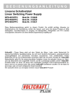
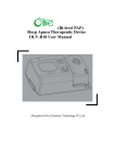
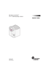
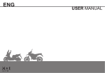
OWNER’S MANUAL
INTRODUCTION
Thanks for your purchasing of the GenericONYX50. This model is designed for safety, built for durability, and
perfected for daily street use. The unique of Generic vehicle design, enrich of stylish and peronality, represents your
outstanding taste and favor to pursue the state of the art living attitude.
This manual describes the correct usage of this motorcycle including safety riding, simple inspection methods and so on.
For a more comfortable and safety riding, please read this manual carefully. If any questions concerning the operation or
maintenance of your scooter, please consult a Generic dealer.
EAU10122
INPORTANT MANUAL INFORMATION
In this manual with some important information is distinguished by the following notations:
1
it is WARNING instructions that need to foloow, failure of follow coulnd be end insult severe injuiry
or lead to death to the operator, a bystander, or a person who is inspecting or repairing the scooter.
2
3
CAUTION:
NOTE:
4
5
6
7
8
9
A CAUTION indicates with special precautions to avoid damage to the scooter.
A NOTE provides key information.
NOTE:
Please always put this manual with vehicle for rider maintenance/ Geberuc dealer tracking of service records even if
vehicle is being sold.
This manual contains the most of the vehicle information, however, Generic will continually imrprove it’s product design
and quality that lead to difference between the manual and vehicle . If you have any questions concerning this manual,
please consult your Generic dealer.
WARNING!!
FOR YOUR OWN SAFETY, PLEASE READ THIS MANUAL CAREFULLY BEFORE OPERATION THIS SCOOTER. ONLY OPERATE
THE SCOOTER UNTIL YOU HAVE COMPLETELY AWARE OF ADEQUATE KNOWLEDGE OF CONTROLS AND OPERATION FEATURE
AND YOU HAVE BEEN TRAINED IN SAFE AND PROPER RIDING TECHNIQUES. PERIODIC INSPECTIONS, WELL MAINTENANCE
AND GOOD RIDING SKILLS, WILL ENSURE YOUR SAFETY RIDING AND INCEASE THE PRODUCT RELIABILITY OF THIS SCOOTER
*Product and specifications are subject to change without notice.
EAU10122
INPORTANT MANUAL INFORMATION
1
2
3
4
Generic Dealer label here
ONYX50 OWNER’S MANUAL
EAU10122
TABLE OF CONTENTS
EAU10210
1
1
SAFETY INFORMATION ................... 1-1
Other safetyriding points.................. 1-3
Location of labels ........................... 1-4
2
DESCRIPTION ................................... 2-1
Left view ......................................... 2-1
3 Right view ....................................... 2-2
2
Controls and instruments ............... 2-3
3
4
5
6
7
8
9
INSTRUMENT AND CONTROL FUNCTIONS ................................................ 3-1
Main switch/steering lock ............... 3-1
Indicator and warning lights ........... 3-2
Dashboard unit ............................... 3-2
Fuel gauge ...................................... 3-3
Handlebar switches ........................ 3-3
Front brake lever ............................. 3-4
Rear brake lever ............................. 3-4
Fuel and 2-stroke engine oil tank
caps ............................................. 3-5
Fuel ................................................. 3-6
Catalytic converter .......................... 3-7
2-stroke engine oil .......................... 3-7
Kickstarter ....................................... 3-7
Seat ................................................ 3-8
Helmet holder ................................. 3-8
Storage luggage Box....................... 3-9
Front hook,helmet .......................... 3-10
Front storage box............................ 3-10
Rear Carrier
............................................. 3-10
Shelf front como(For PIZZA model) .... 3-11
Sidestand / Pedal .............................. 3-11
PRE-OPERATION CHECKS ............. 4-1
Pre-operation check list .................. 4-2
OPERATION AND IMPORTANT RIDING
POINTS .............................................. 5-1
Starting and warming up a cold
engine ......................................... 5-1
Starting off ...................................... 5-2
Acceleration and deceleration ........ 5-3
Braking ........................................... 5-3
Engine break-in .............................. 5-4
Parking ........................................... 5-4
PERIODIC MAINTENANCE AND MINOR
REPAIR .............................................. 6-1
Owner’s tool kit ............................... 6-1
Periodic maintenance chart for the
emission control system .............. 6-2
General maintenance and lubrication
chart ............................................ 6-3
Removing and installing the battery.
cover and cehter cover.....................6-6
Checking the spark plug ................. 6-6
Final transmission oil ...................... 6-8
Cleaning the air filter element ......... 6-9
Carburetor ...................................... 6-10
Checking the throttle cable free
play .............................................. 6-11
Tires ................................................ 6-12
Cast wheels .................................... 6-13
Checking the front brake lever free
play ............................................ 6-13
Adjusting the rear brake lever free
play ............................................ 6-13
Checking the front brake pads and rear
brake shoes ............................... 6-14
Checking the front brake fluid
level ........................................... 6-15
Changing the brake fluid .............. 6-16
Checking and lubricating the
cables ........................................ 6-16
Checking and lubricating the throttle
grip and cable ............................ 6-16
Adjusting the Autolube pump ....... 6-17
Lubricating the front and rear brake
levers ......................................... 6-17
Checking and lubricating the
main stand ............................... 6-18
Checking the front fork ................. 6-18
Checking the steering ................... 6-19
Checking the wheel bearings ....... 6-19
Battery .......................................... 6-20
Replacing the fuse ........................ 6-21
Replacing a headlight bulb............ 6-22
Front turn signal light..................... 6-22
Replacing rear turn signal light bul
-b.................................................... 6-22
Tail/brake and licenes light............ 6-22
Replacing a headlight bulb(For PIZZA m
-odel)............................................. 6-23
Front turn signal light(For PIZZA model)
...................................................... 6-23
EAU10122
TABLE OF CONTENTS
Troubleshooting ................................ 6-23
Troubleshooting chart ....................... 6-24
SCOOTER CLEAN AND STORAGE ... 7-1
Clean.................................................. 7-1
Storage ............................................. 7-3
SPECIFICATIONS ............................... 8-1
CONSUMER INFORMATION .............. 9-1
Identification numbers ...................... 9-1
Warranty information ........................ 9-2
Service plan ...................................... 9-3
Wiring diagram................................... 9-4
EAU10210
EAU10122
SAFETY INFORMATION
THIS SCOOTER ARE TWO WHEEL
SINGLE TRACK VEHICLES. T H E USE
OF SAVETY AND OPERATION MAY
IN DIFFERENT RESULT BY THE USE OF
PROPER RIDING TECHNIQUES OF THE
OPERATOR.
TO REMIND OF OPERATOR, WHO
SHOULD KNOW THE FOLLOWING
REQUIREMENTS BEFORE RIDING .
HE OR SHE SHOULD:
WELL TRAINED AND FIMILIAR
TO ALL THE ASPECTS OF SCOOTER OPERATION.
FULLY READ AND AWARE OF
MAINTENANCE REQUIREMENTS THAT NOTED IN
THIS OWNER’S MANUAL.
OBTAIN QUALIFIED TRAINING &
LEGAL LICENSE FOR OPERATION OF THIS VEHICLE.
WELL AND PROFESSIONAL MAINTENANCE SERVICE FOR OPERATOR AND CERTIFICATED REPAIR SHOP/GENERIC DEALER TO
ACQUIRE GOOD MECHANICAL
CONDITIONS OF VEHICLE.
Safe riding
Always pre-check your vehicle
before riding is key point to prevent
an accident.
please follow the maxium loads
limited of operator and passenger.
Most of accident on the motorists
is cased by automobile driver who
“failure to recognize out the vehicle” and caused mobile/scooter
accidents. Therefore, to make your
-self conspicuous apprear to public
will be very effective in reducing
the change of this kind of accidents
Therefore:
t Wear a brightly colored and protective clothes/Jacket
t Operate the turning signals before turning and slow down the
Speed when approaching and
passthrough the intersection.
t Keep proper distance with other
Motorists, and let them aware of
your location.
t Know your skills and limits.
t Never lend your scooter to oththers who not qualified for riding
2.2
EAU10210
Always follow the legal speed limit
on the scooter and traffic law.
The posture of the operator and
passenger is important for proper
control. properly riding posture can
Keep scooter in balance while riding.
t Operator should sit up-right with
two hand hold on handle bar,
foot on floorboard while driving.
t Passenger should make sure that
he/she can firmly hold on grip or
oeprator with foot step on footrest.
Drving after Acohol drink or other
illegal drugs is strickly prohibited.
This scooter is designed for onroad use only. It is not suitable for
off-road use.
Protective clothing
Properly clothing yourself will keep
you safety from potential accidents:
Always wear an approved helmet.
with face shield to protect your eye
from dust and rain drop.
EAU10122
SAFETY INFORMATION
The wear of proper jacket, shoes,
groves etc., can be better protection,
reducing the degree of injuiry from
un-expected accident.
Never wear loose-fitting clothes,
otherwise they could catch on the
control levers or wheels and cause
injury or an accident.
Never touch the engine or exhaust
system during or after operation.
They become very hot and can
cause burns. Always wear protective clothing that covers your legs,
ankles, and feet.
Modifications
Modifications made to this scooter
that not approved by Generic, or the
removal of original equipment, may
let scooter unsafe for use and cause
severe personal injury. Modifications
may also make your scooter illegal to
use.
Loading and accessories
Adding accessories or cargo to your
scooter may cause the different on the
weight distribution of scooter and influence on the steering & balance.
It may cause possibility of an accident,
Please extremely caution and follow
below limitation when you equipped
with accessories. Below are some general or accessories. Here are some
guidelines to follow if loading
cargo or adding accessories to your
scooter:
Loading
The total weight of the operator, passenger, accessories and cargo must not
exceed the maximum load limit.
Maximum load(not include the vehicle) :
150 kg
When loading within this weight limit,
keep the following in mind:
Cargo and accessory weight
should be kept as low and close to
the scooter as possible. Make sure
to distribute the weight as evenly
as possible on both sides of the
scooter to minimize imbalance or
instability.
Make sure that accessories and cargo
are securely attached to scooter
before riding
2.3
Never attach any large or heavy
items to the handlebar, front fork,
or front fender. Such items can create unstable handling or a slow
steering response.
Accessorries
Genuine Generic accessories have
been specifically designed for use on
this scooter. If need, please contact with
Generic dealer for detail. Since Generic
can not test all other accessories , you
must personally be responble for the
proper selection, installation and use
of non-Generic accessories.
Keep the following guidelines in mind,
when mounting accessories.
Never install accessories or carry
cargo that would influence on the
ground clearance, limit suspension
travel, steering, or obscure lights or
turning lights, reflectors.
Accessories on the handle bar/front
suspension area will cause bad influence on steering the scooter. if you will
install accessories, please keep it as light
in weight and not interfere on steering
the vehicle.
EAU10122
SAFETY INFORMATION
This vehicle is for On-Road
transportation purpose only,
please do not install any of extended cargo carrier as sulky,
that will make scooter unstable
in cross winds and vehicle turns.
while equip with electrical accessories, please consult with qualifiled sories, to make sure such items will not exceed the capacity
of the scooter’s electrical system.
unproper install of such items may
cause a dangerous loss of lights
, lower engine power or even daamge the vehicle.
Gasoline and exhaust gas
GASOLINE IS HIGHLY FLAMMABLE:
t Always turn the engine off
when refueling.
t Take care not to spill any
gasoline on the engine (hot)
or exhaust system when refueling.
t Do not smoke or use Mobile
phone while re-fueling .
Never start the engine or let it run
for any length of time in a closed
area. The exhaust fumes are poisonous and may cause loss of consciousness and death within a
short time.
Always turn the engine off before
leaving the scooter and remove
the key from the main switch.
When parking the scooter, please
note the following:
t The engine and exhaust system
remain hot, therefore, park the
scooter in a place where pedestrians or children are not likely
to touch these hot areas.
t Do not park the scooter on a
slope or soft ground, otherwise
it may fall over.
t Do not lay your scooter to near
flammable place.
In case of swallow any gasoline, or
gasoline get into your eyes, please
see your doctor immeidately. Keep
away the gasoline to your skin and
water.
2.4
Other safe-riding points
Turn the signal before making
turns.
When raining or across on run on
the wet road, Iron Plates, keep your
spped low, slightly using braking to
avoid slipping or even fall down.
Be careful when passing parked
cars. A driver might not see you and
open a door in your path.
EAU10122
SAFETY INFORMATION
Location of labels
There are two labels that in the scooter and location as noted.
1.WARMING LABEL, FUEL
1
2
2.LABEL, ANTI-TAMPERING
GENERIC
2.5
EAU10122
DESCRPTION
Left view
1
2
4
3
5
6
1
2
3
4
5
6
7
1. Front wheel
2. Front brake caliper (page 6-15)
8 turn signal light
3. Front
4. Helmet holder (page 3-8)
5. Storage compartment (page 3-9)
9 turn signal light
6. Rear
7. Rear wheel
8. Adjusting nut (page 6-15)
9. Kickstarter (page 3-7)
10.Air filter element (page 6-10)
11.Battery (page 6-21)
12.Sidestand (page 3-11)
13.Pedal(page 3-11)
12
3.2
11
13 10
9
8
7
EAU10122
DESCRPTION
Right view
14
15
16
17
18
1
2
3
4
5
6
7
8
9
21 20
22
14.Tail/brake light
15.Carrier (page 3-10)
16.Fuel tank cap
17.2-stroke engine oil tank cap
18.Seat (page 3-8)
19.Headlight
20.Spark plug (page 6-7)
21.Mainstand
22.Muffler
3.3
19
EAU10122
DESCRPTION
Controls and instruments
23
25 26
24
27
28
1
2
3
4
29
5
6
30
31
7
32
23.Rear brake lever (page 3-4)
24.Left handlebar switches (page 3-3)
25.Speedometer unit (page 3-2)
26.Fuel gauge (page 3-3)
27.Right handlebar switches (page 3-3)
28.Front brake lever (page 3-4)
29.Throttle grip (page 6-12)
30.Main switch/steering lock (page 3-1)
31.Hook,Helmet (page 3-10)
32.Front storage compartment (page 3-10)
3.4
EAU10122
INSTRUMENT AND CONTROL FUNCTIONS
Main switch/steering lock/seat open OFF “ ”
To unlock the steering
Push the key in, and then turn it to
while still pushing it.
“
”
OP
EN
All electrical systems are off. The key
can be removed.
PUSH
The main switch/steering lock controls
the ignition and lighting systems, and aiso
used to lock the steering, open the luggbox. The various positions are described
as below.
ON “ ”
All electrical circuits are supplied with
power, the engine can be started.
The key cannot be removed.
NOTE:
The headlight, meter lighting and taillight come on automatically when the
engine is started.
CHECK “ ”
The 2-stroke engine oil level warning
light should come on. (See page 3-2.)
LOCK “ ”
The steering is locked, and all electrical
systems are off. The key can be removed.
To open the seat
1. Push the key in from the “ ” position, and then turn it to “ ”
To lock the steering
1. Turn the handlebars all the way to
the left.
2. Push the key in from the “ ” position, and then turn it to “ ” while
still pushing it.
3. Remove the key.
4.2
WARNING
Never turn the key to
“ ” or “ ”
while the vehicle is moving, otherwise the electrical systems will be
switched off, which may result in
loss of control or an accident. Make
sure that the vehicle is stopped before turning the key to “ ” or “ ” .
EAU10122
INSTRUMENT AND CONTROL FUNCTIONS
Indicator and warning lights
1 2 3
1. Turn signal indicator light "
"
2. High beam indicator light "
"
3. 2-stroke engine oil level warning light
"
"
Turn signal indicator light “
”
This indicator light flashes when the turn
signal switch is pushed to the left or
right.
High beam indicator light “
”
This indicator light comes on when the
high beam of the headlight is switched
on.
2-stroke engine oil level warning light
“
”
The warning light comes on when the
key is in the “ ” position or when the
engine oil level in the 2-stroke engine
oil tank is low during operation. If the
warning light comes on during operation, check the oil level and fill the oil tank
with an 2-stroke engine oil.
The warning light should go off after
the 2-stroke engine oil tank has been
refilled.
NOTE:
If the 2-stroke engine oil level warning
light does not come on when the key is
in the “ ” position or does not go off after the 2-stroke engine oil tank has been
refilled, have a Generi c dealer check the
electrical circuit.
Dashboard unit
1
2
1. Speedmeter
2. Odmeter
The dashboard unit is equipped with
a speedometer and an odometer. The
speedometer shows the riding speed.
The odometer shows the total distance
traveled.
CAUTION:
Do not operate the vehicle until you
know that the 2-stroke engine oil
level is sufficient. Lack of engine oil will
damage the engine.
3-2
EAU10122
INSTRUMENT AND CONTROL FUNCTIONS
Fuel gauge
1
2
1. Fuel gauge
The fuel gauge indicates the amount of
fuel in the fuel tank. The needle moves
towards “E” (Empty) as the fuel level
decreases. When the needle reaches
“E”, refuel as soon as possible.
”
High/Low bean switch “
Set this switch to “ ” for the high beam
and to “ ” for the low beam.
Handlebar switches
1
3
1. Dimmer switch "
2. Turn signal switch "
3. Horn switch "
"
"
1
NOTE:
Be take care not let the fuel tank to fully
empty it-self, that cause engine can not
run it-self anymore.
1. Light switch "
2. Start switch "
Turn signal switch “
”
To signal a right-hand turn, push this
switch to “ ”. To signal a left-hand turn,
push this switch to “ ”. When released, the switch returns to the center
position. To cancel the turn signal lights,
push the switch in after it has returned
to the center position.
"
"
3-3
"
Horn switch “ ”
Press this switch to sound the horn.
2
L i g h t switch “
”
Turning the light switch to“
”
turns on the position light,mater light
and taillight.Turning the light switch to
“
”,turns the headlight on also.
EAU10122
INSTRUMENT AND CONTROL FUNCTIONS
Start switch “
”
Push this switch (pull the brkae lever at same
time to the start the engine.
Front brake lever
Rear brake lever
The front brake lever is located on the
right handlebar grip. To apply the front
brake, pull this lever toward the handlebar grip.
The rear brake lever is located on the
left handlebar grip. To apply the rear
brake, pull this lever toward the handlebar grip.
See page 5-1 for starting instructions
prior to starting the engine.
4.5
EAU10122
Fuel and 2-stroke engine oil
tank caps
The fuel tank cap and the 2-stroke engine oil tank cap are located under the
seat. (See page 3-8.)
To install the fuel tank cap
1. Push the fuel tank cap into position
2. Turn the cap clockwise to the original position.
WARNING
Make sure that the fuel tank cap is
properly closed and locked before
riding.
Fuel tank cap
To remo ve the fuel tank cap
1
To access the 2-stroke engine oil tank,
open the storage compartment. (See
page 3-8.)
1. Remove the 2-stroke engine oil
tank cap by pulling it off.
2. Install the 2-stroke engine oil tank
cap by pushing it into the oil tank
opening.
2-stroke engine oil tank cap
1
NOTE:
Make sure that the 2-stroke engine oil
tank cap is properly installed before
riding the vehicle.
1. Fuel tank cap
To remove the fuel tank cap
1. Turn it 1/4 turn counterclockwise.
The lock will be released and the
fuel tank cap can be removed.
1. 2-stroke engine oil tank cap
4.6
EAU10122
INSTRUMENT AND CONTROL FUNCTIONS
Fuel and 2-stroke engine oil
2
1
CAUTION:
Immediately wipe off spilled fuel with
a clean, dry, soft cloth, since fuel may
damage the painted surfaces or plastic parts.
Recommended fuel:
REGULAR UNLEADED GASOLINE ONLY
Fuel tank capacity:
5.5 L
1. Fuel tank filler tube
2. Fuel level
Make sure that there is sufficient fuel in
the tank. Fill the fuel tank to the bottom
of the filler tube as shown.
Do not overfill the fuel tank, otherwise it may overflow when the
fuel warms up and expands.
Avoid spilling fuel on the hot
engine.
Your Generic engine has been designed
to use regular unleaded gasoline of 90
or higher. If knocking (or pinging) occurs,
use a gasoline of a different brand or
premium unleaded fuel.
Gasohol
There are two types of gasohol: gasohol containing ethanol and that containing methanol. Gasohol containing ethanol can be used if the ethanol content
4.7
does not exceed 10%. Gasohol containing methanol is not recommended by
Generic because it can cause damage
to the fuel system or vehicle performance problems.
EAU10122
INSTRUMENT AND CONTROL FUNCTIONS
Catalytic converter
2-stroke engine oil
This model is equipped with a catalytic
converter in the exhaust system.
Make sure that there is sufficient 2stroke engine oil in the oil tank. Add the
recommended 2-stroke engine oil as
necessary.
The exhaust system is hot after operation. Make sure that the exhaust
system has cooled down before doing any maintenance work.
Kickstarter
1
1
CAUTION:
The following precautions must be
observed to prevent a fire hazard or
other damages.
Use only unleaded gasoline.The
use of leaded gasoline will cause
unrepairable damage to the
catalytic converter.
Never park the vehicle near possible fire hazards such as grass
or other materials that easily
burn.
Do not allow the engine to idle
too long.
1. Kickstarter lever
1. 2-stroke engine oil tank cap
Recommended oil:
(See page 8-1).
Oil quantity:
0.85 L
NOTE:
Make sure that the 2-stroke engine oil
tank cap is properly installed.
4.8
To star t the engine, fold out the
kickstarter lever, move it down lightly
with your foot until the gears engage,
and then push it down smoothly but
forcefully.
EAU10122
INSTRUMENT AND CONTROL FUNCTIONS
Seat
3. Fold the seat up.
To open the seat
1. Place the scooter on the cen
-terstand.
2. Insert the key into the main switch,
and then turn it counterclockwise
to “OPEN”.
Helmet holder
1
1
OP
EN
OPEN
4
PUSH
NOTE:
Do not push inward when turning the
key.
1. Seat
1. Helmet holder
To close the seat
1. Fold the seat down, and then push
it down to lock it in place.
2. Remove the key from the main
switch if the scooter will be left unattended.
The helmet holder is located under the
seat.
NOTE:
Make sure that the seat is properly secured before riding.
To secure a helmet to the helmet
holder
1. Open the seat.
2. Attach the helmet to the helmet
holder, and then securely close the
seat.
Never ride with a helmet attached to
the helmet holder, since the helmet
may hit objects, causing loss of control and possibly an accident.
4.9
EAU10122
INSTRUMENT AND CONTROL FUNCTIONS
To take out the helmet from the helmet holder
Open the seat, take out the helmet from
the helmet holder, and then close the
seat.
Storage Luggage Box
1
1. Storage luggage box
There is a storage compartment under
the seat. (See page 3-8, 3-9)
Since the storage luggage box
will accumulates heat by the heat
of sun and engine, please do not put
any thing that sentitive to the heat.
Since the storage luggage box
may get wet while the scooter is
being washed, please storage the
related objects if need with plastic
bag to prevent it from getting wet.
Do not put anything valuable
or breakable objects in the storage
luggage box
To store a helmet in the storage luggages box, place the helmet upsidedown with the front facing forward.
Do not exceed the load limit of 2
.5kg for the storage luggage box
Do not exceed the maximum
load of 150 kg for the vehicle.
CAUTION:
Keep the following points in mind
when using the storage Luggage Box
4.:
NOTE:
Some helmets cannot be stored in
the storage luggauge box because
of their size or shape.
Before you leave the scooter, make
sure the seat is closed firmly
EAU10122
INSTRUMENT AND CONTROL FUNCTIONS
Front hook,helmet
Front storage box
Rear Carrier
1
1
1
1. Front hook,helmet
1. Front storage box
Front hook.helmet
To open the front storge box when it is
locked,insert the key and turn clockiwse
direction to open it
To lock the front storage box, put the lid
back to the original position,turn it anticlockwise direction and pull back the key.
Do not exceed the load limit of 1
kg for the front Hook
1. Rear Carrier
Do not exceed the load limit of 0
.5kg for the front storage box.
Do not exceed the maximum
load of 150 kg for the vehicle.
4.21
Do not exceed the load limit of 2.5
kg for the carrier.
Do not exceed the maximum
load of 150 kg for the vehicle.
EAU10122
INSTRUMENT AND CONTROL FUNCTIONS
Shelf front comp (for pizza model)
Sidestand(optional accessories)
Pedal
1
1
1
1. Shelf front comp
WARNING!!
Do not exceed the load limit of 5
kg for the shelf front comp.
Do not exceed the maximum
load of 150 kg for the vehicle.
1. Side stand
1. Pedal
The side stand is located on the left side
of the Vehicle. Reiease the sidestand by
using your feet to step on the bracket of
side stand to up-right position to stand
the vehicle.
The pedal is located on the left side and
right side of the vehicle. When you want
use it,open the pedal by pulling it .
The side stand with auto-rebound
system. Make sure your scooter have
been park well are stable enough
to stand the scooter.
Please avoid to use side stand to
park the scooter on the slope, soft
land or un-flat ground.
4.22
When you don’t want to use it,close the
pedal by pushed it and get back to the
original position.
EAU10122
PRE-OPERATION CHECKS
EAU15580
The condition of a vehicle is the owner’s responsibility. The operator should check the scooter by simple but thorough inspection,
to make sure of scooter condition, quick inspect some key and important parts, to prevent the scooter from serious consquence/accident.
Please carefully check the following points before each ride.
NOTE:
Pre-operation checks should be made each time the vehicle is used. Such an inspection can be accomplished in a very
short time; and the added safety it assures is more than worth the time involved.
If any item in the Pre-operation check list is not working properly , have it inspected and repaired before operating the vehicle.
If failed to be corrected by yourself, please turn to GENERIC repair shop immediately.
5.2
EAU10122
PRE-OPERATION CHECKS
Pre-operation check list
IT E M
C HE C K S
PAGE
Fuel
t Check fuel level in fuel tank.
t Refuel if necessary.
t Check fuel line for leakage.
3-6
2-stroke engine oil
t Check oil level in oil tank.
t If necessary, add recommended oil to specified level.
t Check vehicle for oil leakage.
3-5
Final transmission oil
t C he c k ve hic le for oil le a k a ge .
6 -8
Front brake
t
t
t
t
t
t
t
Check operation.
If soft or spongy, have Generic dealer bleed hydraulic system.
Check brake pads for wear.
Replace if necessary.
Check fluid level in reservoir.
If necessary, add recommended brake fluid to specified level.
Check hydraulic system for leakage.
6-14 ~6-16
Rear brake
t
t
t
t
Check operation.
Lubricate cable if necessary.
Check lever free play.
Adjust if necessary.
6-13 ~6-14
Throttle grip
t Make sure that operation is smooth.
t Check cable free play.
t If necessary, have Generic dealer adjust cable free play and lubricate cable and
grip housing.
Wheels and tires
t
t
t
t
Brake levers
t Make sure that operation is smooth.
t Lubricate lever pivoting points if necessary.
Check for damage.
Check tire condition and tread depth.
Check air pressure.
Correct if necessary.
6-11, 6-16
6-12~6-13
5.3
6-17
EAU10122
PRE-OPERATION CHECKS
IT E M
C HE C K S
Main stand
t Make sure that operation is smooth.
t Lubricate pivot if necessary.
Chassis fasteners
t Make sure that all nuts, bolts and screws are properly tightened.
t Tighten if necessary.
Instruments, lights, signals
and switches
t Check operation.
t Correct if necessary.
PAGE
6-18
3-2 ~3-3
5.4
EAU10122
OPERATION AND IMPORTANT RIDING POINTS
Before riding the scooter, please
make sure that you are fully fimiliar with all operating controls &
their functions before riding. To
consult a Generic dealer shop if
you not thoroughly understand.
Please do not start the engine in
a closed area, the exhaust air are
are poisonous, and inhaling
them can cause loss of consciousness and even death in
short time.
Starting and warming up a
cold engine
CAUTION:
See page 5-4 for engine break-in instructions prior to operating the vehicle for the first time.
CAUTION:
If the 2-stroke engine oil level warning light does not come on, have a
Generic dealer check the electrical
circuit.
3. Close the throttle completely.
1
1
1. Kickstarter lever
1. Engine start switch “
”
1. Turn the key to “
”, and when
the 2-stroke engine oil level warn
-ing light comes on, turn the key
to“ON ”.
6.2
4. Start the engine by pushing the
start switch or by pushing the
kickstarter lever down, while applying the front or rear brake.
NOTE:
If the engine fails to start by pushing
the start switch, release the switch, wait
a few seconds, and then try again. Each
EAU10122
OPERATION AND IMPORTANT RIDING POINTS
starting attempt should be as short as
possible to preserve the battery. Do not
crank the engine more than 5 seconds
on any one attempt. If the engine does
not start with the starter motor, try using the kickstarter.
CAUTION:
For maximum engine life, always
warm the engine up before starting
off. Never throttle hard when the
engine is still cold!
Starting off
NOTE:
Before starting off, allow the engine to
warm up.
1. While pulling the rear brake lever
with your left hand and holding the
carrier with your right hand, push
the scooter off the main stand.
2. Sit astride the seat, and then adjust the rear view mirrors.
3. Switch the turn signal on to the direction you wish to turn.
6.3
4. Check for oncoming traffic, and
then slowly turn the throttle grip (on
the right) in order to take off.
5. Switch the turn signal off.
EAU10122
OPERATION AND IMPORTANT RIDING POINTS
Acceleration and deceleration
(b)
Braking
1. Close the throttle completely.
2. Apply both front and rear brakes
simultaneously while gradually increasing the pressure.
FRONT
(a)
The speed can be adjusted by opening
and closing the throttle. To increase the
speed, turn the throttle grip in direction
(a).To reduce the speed, turn the throttle
grip in direction (b).
REAR
6.4
Avoid braking hard or suddenly
, otherwise the scooter may skid
Railroad crossings, streetcar
rails, iron plates on road construction sites, and manhole
covers become extremely slippery when wet. Therefore, slow
down when approaching such
areas and cross them with caution.
Keep in mind that braking on a
wet road is much more difficult.
Ride slowly down a hill, as braking downhill can be very difficult.
EAU10122
OPERATION AND IMPORTANT RIDING POINTS
Engine break in
There is never a more important period
in the life of your engine than the period
between 0 and 1000 km. For this reas
-on, you should read the following mate
-rial carefully.
Since the engine is brand new, do not
put an excessive load on it for the first
1000 km . The various parts in the eng
-ine wear and polish themselves to the
correct operating clearances.
During this period, prolonged full-throttle
operation or any condition that might
result in engine overheating must be
avoided.
0 ~ 150 km
Avoid prolonged operation above 1/3
throttle. Vary the speed of the scooter
from time to time. Do not operate it at
one set throttle position.
500 ~ 1000 km
Avoid cruising speeds in excess of 3/4
throttle.
CAUTION:
Parking
When parking, stop the engine, and
then remove the key from the main
switch.
After 1000 km of operation,the final
transmission oil must be changed.
1000 km and beyond
Avoid prolonged full throttle operation.
Vary speeds occasionally.
CAUTION:
If any engine trouble should occur
during the engine break-in period,
immediately have a Generic dealer
check the vehicle.
Since the engine and exhaust
system can become very hot,
park in a place where pedestrians or children are not likely to
touch them.
Do not park on a slope or on soft
ground, otherwise the vehicle
may overturn.
CAUTION:
Never park in an area where there are
fire hazards such as grass or other
flammable materials.
150 ~ 500 km
Avoid prolonged operation above 1/2
throttle.
6.5
EAU10122
PERIODIC MAINTENANCE AND MINOR REPAIR
Most of the Safety and condition of
scooter depend on how you do the correct maintenance , periodic inspection,
adjustment and lubrication. The following are contents that help the
operator to do such skills on the following pages.
Maintenance, replacement, or repair
of the emission control devices and
systems may be performed by any
repair shop or individual that is
certified and must follow the local
law regulations.
WARNING!!
If you are not familiar with maintenance work, have a GEBERIC dealer do
it for you.
Owner’s tool kit
1
NOTE:
If you do not have the tools or experience required for a particular job, have
a Generic dealer perform it for you.
Modifications not approved by
Generic may cause loss of performance, excessive emissions, and
render the vehicle unsafe for use.
Consult a Generic dealer before attempting any changes.
1. Owner’s tool kit
The owner’s tool kit is located inside the
rear storage luggage box (See page
3-9.)
The service information included in this
manual and the tools provided in the
owner’s tool kit are intended to assist
you in the performance of preventive
maintenance and minor repairs. However, additional tools such as a torque
wrench may be necessary to perform
certain maintenance work correctly.
7.2
EAU10122
PERIODIC MAINTENANCE AND MINOR REPAIR
Periodic maintenance chart for the emission control system
IN IT IA L
NO .
IT E M
R O U T IN E
1
* Fuel line
t Check fuel and vacuum hoses for
cracks or damage.
t Replace if necessary.
2
* Idle speed
t Check and adjust engine idle
speed.
3
* Exhaust system
t Check for leakage.
t Tighten if necessary.
t Replace gasket(s) if necessary.
4
* Air induction system
t Check the air cut-off valve, reed
valve, and hose for damage.
t Replace any damaged parts.
O D O ME T E R R E A D I N G
1,000 km
4,000 km
7,000 km
10,000 km
13,000 km
16,000 km
or
1
month
or
6
months
or
12
months
or
18
months
or
24
months
or
30
months
* Since these items require special tools, data and technical skills, have a Generic dealer perform the service.
7.3
EAU10122
PERIODIC MAINTENANCE AND MINOR REPAIR
General maintenance and lubrication chart
IN IT IA L
NO .
IT E M
R O U T IN E
1
* Air filter element
t Clean with solvent.
t Replace if necessary.
2
* Front brake
t Check operation, fluid level, and for
fluid leakage.
t Replace brake pads if necessary.
3
* Rear brake
t Check operation.
t Adjust cable and replace brake
shoes if necessary.
4
* Wheels
t Check runout and for damage.
t Replace if necessary.
5
* Tires
t Check tread depth and for damage.
t Replace if necessary.
t Check air pressure.
t Correct if necessary.
6
* Wheel bearings
t Check bearings for smooth
operation.
t Replace if necessary.
* Steering bearings
t Check bearing assemblies for
looseness.
t Moderately repack with lithiumsoap-based grease every 10000 mi
(16000 km) or 18months.
7
O D O ME T E R R E A D I N G
1,000 km
4,000 km
7,000 km
10,000 km
13,000 km
16,000 km
or
1
month
or
6
months
or
12
months
or
18
months
or
24
months
or
30
months
Repack.
7.4
EAU10122
PERIODIC MAINTENANCE AND MINOR REPAIR
IN IT IA L
NO .
IT E M
R O U T IN E
* Chassis fasteners
9
Front brake lever
pivot shaft
t Apply silicone grease lightly.
10
Rear brake lever
pivot shaft
t Apply lithium-soap-based grease
(all-purpose grease) lightly.
11
Centerstand
t Check operation.
t Lubricate.
* Front fork
13
* assembly
t Check operation and for oil
leakage.
t Replace if necessary.
14
* Autolube pump
t Check operation.
t Bleed if necessary.
16
17
Final transmission
oil
* V-belt
Control and meter
* cables
7,000 km
or
12
months
10,000 km
or
18
months
t Check operation and for oil
leakage.
t Replace if necessary.
12
15
4,000 km
or
6
months
t Check all chassis fitting and
fasteners.
t Correct if necessary.
8
Shock absorber
1,000 km
or
1
month
O D O ME T E R R E A D I N G
t Check vehicle for oil leakage.
t Change.
t R e pla c e .
E v e ry
t Apply Generic chain and cable
lube or engine oil 10W-30
thoroughly.
7.5
1 0 0 0 0 km
13,000 km
or
24
months
16,000 km
or
30
months
EAU10122
PERIODIC MAINTENANCE AND MINOR REPAIR
IN IT IA L
NO .
IT E M
R O U T IN E
1
2
Throttle grip housing
and cable
18
*
19
* switches
3
4
Lights, signals and
O D O ME T E R R E A D I N G
1,000 km
4,000 km
7,000 km
10,000 km
13,000 km
16,000 km
or
1
month
or
6
months
or
12
months
or
18
months
or
24
months
or
30
months
t Check operation and free play.
t Adjust the throttle cable free play if
necessary.
t Lubricate the throttle grip housing
and cable.
t Check operation.
t Adjust headlight beam.
* Since these items require special tools, data and technical skills, have a Generic dealer perform the service.
5
NOTE:
From 19000 km or 36 months, repeat the maintenance intervals starting from 7000 km or 12 months.
7
NOTE:
The air filter needs more frequent service if you are riding in unusually wet or dusty areas.
Hydraulic brake system
t When disassembling the master cylinder or caliper cylinder, always replace the brake fluid. Check the brake fluid
level regularly and fill as required.
t Replace the brake hoses every four years or if cracked or damaged.
8
9
7.6
EAU10122
PERIODIC MAINTENANCE AND MINOR REPAIR
Removing and installing the
battery cover and center cover
(To install the cover)
Place the cover in the original position,
and then install the screws.
2( 2)
1
Checking the spark plug
2
1
1. Battery cover
2.Center cover
The covers shown needs to be removed
to perform some of the maintenance
jobs described in this chapter.
1. Battery cover
2. Screw
(To remove the cover)
Remove the screws, and then take the
cover off.
Battery cover
(To remove the cover)
Remove the screws, and then take the
cover off.
(To install the cover)
Place the cover in the original position,
and then install the screws.
Center cover
2( 4)
The spark plug is an important engine
component, which is easy to check.
Since heat and deposits will cause any
spark plug to slowly erode, the spark
plug should be removed and checked
in accordance with the periodic maintenance and lubrication chart. In addition, the condition of the spark plug can
reveal the condition of the engine.
To remove the spark plug
1. Remove cover. (See page 6-7)
2. Remove the spark plug cap.
1
1
1. Center cover
2. Screw
1. Spark plug cap
7.7
EAU10122
PERIODIC MAINTENANCE AND MINOR REPAIR
3. Remove the spark plug as shown,
with the spark plug wrench included in the owner’s tool kit.
2. Check the spark plug for electrode
erosion and excessive carbon or
other deposits, and replace it if
necessary.
Specified spark plug:
BR8HSA (NGK)
1
To install the spark plug
1. Measure the spark plug gap with a
wire thickness gauge and, if necessary, adjust the gap to specification.
1. Spark plug wrench
To check the spark plug
1. Check that the porcelain insulator
around the center electrode of the
spark plug is a medium-to-light tan
(the ideal color when the vehicle is
ridden normally).
NOTE:
If the spark plug shows a distinctly different color, the engine could be operating improperly. Do not attempt to diagnose such problems yourself. Instead, have a Genericdealer check the
vehicle.
2. Clean the surface of the spark plug
gasket and its mating surface, and
then wipe off any grime from the
spark plug threads.
3. Install the spark plug with the spark
plug wrench, and then tighten it to
the specified torque.
Tightening torque:
Spark plug:
18 Nm
NOTE:
If a torque wrench is not available when
installing a spark plug, a good estimate
of the correct torque is 1/4 ~ 1/2 turn
past finger tight. However, the spark
plug should be tightened to the specified torque as soon as possible.
4. Install the spark plug cap.
5. Install the panel.
1
1. Spark plug gap
Spark plug gap:
0.6 ~ 0.7 mm
7.8
EAU10122
PERIODIC MAINTENANCE AND MINOR REPAIR
Final transmission oil
Tightening torque:
Final transmission oil drain bolt:
18 Nm
The final transmission case must be
checked for oil leakage before each ride.
If any leakage is found, have a Generic
dealer check and repair the scooter. In
addition, the final transmission oil must
be changed as follows at the intervals
specified in the periodic maintenance
and lubrication chart.
1. Start the engine, warm up the final
transmission oil by riding the
scooter for several minutes, and
then stop the engine.
2. Place the scooter on the main
stand.
3. Place an oil pan under the final
transmission case to collect the
used oil.
4. Remove the oil filler cap and drain
bolt to drain the oil from the final
transmission case.
1
6. Add the requested amount of the
recommended final transmission
oil, and then install and tighten the
oil filler cap.
Recommended final transmission
oil:
1. Final transmission oil filler cap
Castrol MTX Part Snth. 80W od. EP 80W-90
5. Install the final transmission oil
drain bolt, and then tighten it to the
specified torque.
1
(See page 8-1).
Oil quantity:
Full: 0.13L/ Change: 0.11 L
WARNING!!
Make sure that no foreign material enters the final transmission
case.
Make sure that no oil gets on the
tire or wheel.
7. Check the final transmission case
for oil leakage. If oil is leaking,
check for the cause.
1. Final transmission oil drain bolt
7.9
EAU10122
PERIODIC MAINTENANCE AND MINOR REPAIR
Cleaning the air filter element
2( 1)
1
2( 4)
2( 7)
1
1
1. Band
2. Screw
1. Air filter case cover
2. Screw
1. Seat&storage compartment
2. Bolt
The air filter element should be cleaned
at the intervals specified in the periodic
maintenance and lubrication chart.
Clean the air filter element more frequently if you are riding in unusually wet
or dusty areas.
1. Open the seat (See page 3-8)
2. Remove the Fuel tank cap and oil
tank cap(See page 3-5)
3. Remove the seat and storage lu-ggage box by removing the bolt.
4. Remove t h e a i r fi l t e r band .
2( 2)
1
1
1. Air filter case
2. Screw
1. Air filter element
5. Remove air filter case by re
-moving the screws on the c
-rankcase side.
6. Remove the air filter case cove
by removing the screws.
7.:
7. Pull the air filter element out.
8. Clean the air filter element with
solvent, and then squeeze the
remaining solvent out.
EAU10122
PERIODIC MAINTENANCE AND MINOR REPAIR
WARNING!!
Use only a dedicated parts cleaning
solvent. To avoid the risk of fire or
explosion, do not use gasoline or
solvents with a low flash point.
CAUTION:
To avoid damaging the air filter element, handle it gently and carefully,
and do not twist it.
1
3
2
4
Recommended oil:
2-stroke engine oil
8. Coat the mating surfaces of the air
filter case and air filter case cover
lightly with grease for an airtight
seal.
9. Install the air filter element.
10. Install the air filter case cover by
installing the screws.
11. Install the air filter case by installing the screws, and then install the
air filter joint band.
12. Install the the set and storage co
mpartment by installing the bolt.
13. Install the Fuel tank cap and oil ta
-nk cap(See page 3-5)
14. Close the seat.
7. Apply oil of the recommended type
to the entire surface of the air filter
element, and then squeeze the
excess oil out.
NOTE:
The air filter element should be wet but
not dripping.
7.21
CAUTION:
Make sure that the air filter element is properly seated in the air
filter case.
The engine should never be operated without the air filter element installed, otherwise the
piston and/or cylinder may become excessively worn.
Carburetor
The carburetor is an important part of
the engine and its emission control system, which requires very sophisticated
adjustment. Therefore, carburetor adjustments should be left to Generic
dealer, who has the necessary professional knowledge and experience.
EAU10122
PERIODIC MAINTENANCE AND MINOR REPAIR
Checking the throttle cable
free play
1
1. Throttle cable free play
The throttle cable free play should measure 1.5 ~ 3.5 mm at the throttle grip.
Periodically check the throttle cable free
play and, if necessary,have a Generic
dealer adjust it.
Tires
To maximize the performance, durability, and safe operation of your scooter,
note the following points regarding the
specified tires.
Tire air pressure
The tire air pressure should be checked
and, if necessary, adjusted before each
ride.
WARNING!!
The tire air pressure must be
checked and adjusted on cold
tires (i.e., when the temperature
of the tires equals the ambient
temperature).
The tire air pressure must be
adjusted in accordance with the
riding condition. If you are not
fimiliar to this, please have
Generic dealer for help.
7.22
Tire air pressure (measured on cold
tires):
Front:
235 kPa
Rear:
235 kPa
Maximum load*:
150 kg
* Total weight of rider, passenger,
cargo and accessories
WARNING!!
Do not over load your scooter, since
it will increase pressure on the tire,
braking, steering than original design,
and may could cause damage or even
lead to accident.
Allocation of your cargo and weight of
your vehicle is very important for your
own safety and vehicle performance.
Load your cargo firmly on vehicle and
put the heaviest cargo to the center
of scooter, then distribute the weight
evenly from side to side. It will keep
you to have good steering after load.
EAU10122
PERIODIC MAINTENANCE AND MINOR REPAIR
Tire inspection
sidewall is cracked, have a Generic
dealer replace the tire immediately.
1
2
3
Minimum tire tread depth (front and
rear):
Front : 1.6 mm
Rear: 2.0mm
NOTE:
The tire tread depth limits may differ
from country to country. Always comply
with the local regulations.
1. Tire tread depth
2. Tire sidewall
3. Tire wear indicator
The tires must be checked before each
ride. If a tire tread shows crosswise lines
(minimum tread depth), if the tire has a
nail or glass fragments in it, or if the
Tire information
This scooter is equipped with cast
wheels and tubeless tires with valves.
WARNING!!
Operating the scooter with excessively worn tires decrease riding stability and can lead to loss of control.
Please replace the excessive worn tires
by a Generic dealer immediately.
Brakes, tires, and related wheel parts
replacement should be left to a
Generic Service Technician.
7.23
Front tire:
Size:
80/80-16 46J
Manufacturer/model:
KENDA/K488
Rear tire:
Size:
90/80-16 52J
Manufacturer/model:
KENDA/K488
EAU10122
PERIODIC MAINTENANCE AND MINOR REPAIR
Cast wheels
To maximize the performance, durability, and safe operation of your motorcycle, note the following points regarding the specified wheels.
The wheel rims should be checked
for cracks, bends or warpage before each ride. If any damage is
found, have a Generic dealer replace the wheel. Do not attempt
even the smallest repair to the
wheel. A deformed or cracked
wheel must be replaced.
The wheel should be balanced
whenever either the tire or wheel
has been changed or replaced. An
unbalanced wheel can result in
poor performance, adverse handling characteristics, and a shortened tire life.
Ride at moderate speeds after
changing a tire since the tire surface must first be “broken in” for it
to develop its optimal characteristics.
Checking the front brake lever
free play
There should be no free play at the
brake lever end. If there is free play, have
a Genericdealer inspect
the brake system.
WARNING!!
A soft or spongy feeling in the brake
lever can indicate the presence of air
in the hydraulic system. If there is air
in the hydraulic system, have a
Generic dealer bleed the system before operating the motorcycle. Air in
the hydraulic system will diminish
the braking performance, which may
result in loss of control and an accident.
7.24
Adjusting the rear brake lever
free play
1
1. Rear brake lever free play
The brake lever free play should measure 10 ~ 20 mm as shown.
Periodically check the brake lever free
play and, if necessary, adjust it as follows.
To increase the brake lever free play,
turn the adjusting nut at the brake shoe
plate in direction (a). To decrease the
brake lever free play, turn the adjusting
nut in direction (b).
EAU10122
PERIODIC MAINTENANCE AND MINOR REPAIR
Checking the front brake pads
and rear brake shoes
(a)
1
(b)
The front brake pads and the rear brake
shoes must be checked for wear at the
intervals specified in the periodic maintenance and lubrication chart.
of the wear indicators while applying the
brake. If a brake pad has worn to the
point that a wear indicator almost
touches the brake disc, have a Generic
dealer replace the brake pads as a set.
Rear brake shoes
Front brake pads
1. Adjusting nut
1
1
WARNING!!
If proper adjustment cannot be obtained as described, have a Generic
dealer make this adjustment.
2
2
3
1. Wear indicator
2. Wear limit line
1. Wear indicator
2. Brake disc
3. Brake pad
Each front brake pad is provided with
wear indicators, which allows you to
check the brake pad wear without having to disassemble the brake. To check
the brake pad wear, check the position
7.25
The rear brake is provided with a wear
indicator, which allows you to check the
brake shoe wear without having to disassemble the brake.To check the brake
shoe wear, check the position of the
wear indicator while applying the brake.
If a brake shoe has worn to the point
that the wear indicator reaches the wear
EAU10122
PERIODIC MAINTENANCE AND MINOR REPAIR
limit line, have a Genericdealer replace
the brake shoes as a set.
Checking the front brake fluid
level
1
make sure that the top of the master cylinder is level by turning the
handlebars.
t Use only the recommended quality brake fluid, otherwise the rubber seals may deteriorate, causing
leakage and poor braking performance.
Recommended brake fluid:
DOT 3/4
1. Minimum level mark
Insufficient brake fluid may allow air to
enter the brake system, possibly causing it to become ineffective.
Before riding, check that the break fluid
is above the minimum level mark and
refill it if necessary. Low position brake fluid
level may indicate worn brake pads and/
or brake system leakage. If the brake
fluid level is low, be sure to check the
brake pads for wear and the brake system for leakage.
Observe these precautions:
t When checking the fluid level,
7.26
t Refill with the same type of brake
fluid. Mixing fluids may result in a
harmful chemical reaction and lead
to poor braking performance.
t Be careful that water does not enter the master cylinder when refilling.Water will significantly lower the
boiling point of the fluid and may
result in vapor lock.
t Brake fluid may deteriorate painted
surfaces or plastic parts. Always
clean up spilled fluid immediately.
t As the brake pads wear, it is normal for the brake fluid level to
gradually go down. However, if the
brake fluid level goes down suddenly, have aGenericdealer check.
EAU10122
PERIODIC MAINTENANCE AND MINOR REPAIR
Changing the brake fluid
Have a Generic dealer change the
brake fluid at the intervals specified in
the NOTE after the periodic maintenance and lubrication chart.
Checking and lubricating the
cables
Checking and lubricating the
throttle grip and cable
The operation of all control cables and
the condition of the cables should be
checked before each ride, and the
cables and cable ends should be lubricated if necessary. If a cable is damaged or does not move smoothly, have
a Generic dealer check or replace it.
The operation of the throttle grip should
be checked before each ride. In addition, the cable should be lubricated at
the intervals specified in the periodic
maintenance chart.
Recommended lubricant:
engine oil SAE 10W-30
Damage to the outer housing of
cables may result in internal rusting
and cause interference with cable
movement. Replace damaged cables
as soon as possible to prevent unsafe conditions.
7.27
EAU10122
PERIODIC MAINTENANCE AND MINOR REPAIR
Adjusting the Autolube pump
The Autolube pump is a vital and sophisticated component of the engine,
which must be adjusted by a Generic
dealer at the intervals specified in the
periodic maintenance and lubrication
chart.
Lubricating the front and rear
brake levers
Front brake lever
The pivoting points of the front and rear
brake levers must be lubricated at the
intervals specified in the periodic maintenance and lubrication chart.
Recommended lubricants:
Front brake lever:
Silicone grease
Rear brake lever:
Lithium-soap-based grease
(all-purpose grease)
Rear brake lever
7.28
EAU10122
PERIODIC MAINTENANCE AND MINOR REPAIR
Checking and lubricating the
Main stand
Checking the front fork
The condition and operation of the front
fork must be checked as follows at the
intervals specified in the periodic maintenance and lubrication chart.
To check the condition
Securely support the motorcycle so
that there is no danger of it falling
over.
The operation of the main stand should
be checked before each ride, and the
pivots and metal-to-metal contact surfaces should be lubricated if necessary.
If the main stand does not move up
and down smoothly, have a Generic
dealer check or repair it.
Recommended lubricant:
Lithium-soap-based grease (all-purpose grease)
Check the inner tubes for scratches,
damage and excessive oil leakage.
To check the operation
1. Place the motorcycle on a level surface and hold it in an upright position.
2. While applying the front brake,
push down hard on the handlebars
several times to check if the front
fork compresses and rebounds
smoothly.
7.29
CAUTION:
If any damage is found or the front
fork does not operate smoothly, have
a Generic dealer check or repair it.
EAU10122
PERIODIC MAINTENANCE AND MINOR REPAIR
Checking the steering
Checking the wheel bearings
Worn or loose steering bearings may
cause danger. Therefore, the operation
of the steering must be checked as follows at the intervals specified in the
periodic maintenance and lubrication
chart.
1. Place a stand under the engine to
raise the front wheel off the ground.
The front and rear wheel bearings must
be checked at the intervals specified in
the periodic maintenance and lubrication chart. If there is play in the wheel
hub or if the wheel does not turn
smoothly, have a Genericdealer check
the wheel bearings.
Securely support the motorcycle so
that there is no danger of it falling
over.
2. Hold the lower ends of the front fork
legs and try to move them forward
and backward. If any free play can
be felt, have a Generic dealer
check or repair the steering.
7.2:
EAU10122
PERIODIC MAINTENANCE AND MINOR REPAIR
CHILDREN.
Battery
1
1. Battery
The battery is located behind battery
cover.(See page 6-6.)
This model is equipped with a sealedtype (MF) battery, which does not require any maintenance. There is no
need to check the electrolyte or to add
distilled water.
CAUTION:
Never attempt to remove the battery
cell seals, as this would permanently
damage the battery.
Electrolyte is poisonous and
dangerous since it contains sulfuric acid, which causes severe
burns. Avoid any contact with
skin, eyes or clothing and always
shield your eyes when working
near batteries. In case of contact,
administer the following FIRST
AID.
t EXTERNAL: Flush with
plenty of water.
t INTERNAL: Drink large
quantities of water or milk
and immediately call a
physician.
t EYES: Flush with water for
15 minutes and seek prompt
medical attention.
Batteries produce explosive hydrogen gas. Therefore, keep
sparks, flames, cigarettes, etc.,
away from the battery and provide sufficient ventilation when
charging it in an enclosed space.
KEEP THIS AND ALL BATTERIES OUT OF THE REACH OF
7.31
To charge the battery
Have a Generic dealer charge the battery as soon as possible if it seems to
have discharged. Keep in mind that the
battery tends to discharge more quickly
if the vehicle is equipped with optional
electrical accessories.
To store the battery
1. If the vehicle will not be used for
more than one month, remove the
battery, fully charge it, and then
place it in a cool, dry place.
2. If the battery will be stored for more
than two months, check it at least
once a month and fully charge it if
necessary.
3. Fully charge the battery before installation.
4. After installation, make sure that
the battery leads are properly connected to the battery terminals.
CAUTION:
Always keep the battery
charged. Storing a discharged
EAU10122
PERIODIC MAINTENANCE AND MINOR REPAIR
battery can cause permanent
battery damage.
To charge the battery, please
make sure the amper and volts
of charger that sutiable to the MF
battery and the specific type.
If you do not fimilar to the battery charging, please have
a Generic dealer to charge your
battery.
Replacing the fuse
CAUTION:
Do not use a fuse of a higher amperage rating than recommended to
avoid causing extensive damage to
the electrical system and possibly a
fire.
1
1. Fuse
The fuse holder is located behind batter
-y cover. (See page 6-7.)
If the fuse is blown, replace it as follows.
1. Turn the key to “ ” and turn off
all electrical circuits.
2. Remove the blown fuse, and then
install a new fuse of the specified
amperage.
Specified fuse:
10 A
7.32
3. Turn the key to “ ” and turn on
the electrical circuits to check if the
devices operate.
4. If the fuse immediately blows again,
have a Generic dealer check the
electrical system.
EAU10122
PERIODIC MAINTENANCE AND MINOR REPAIR
Replacing a headlight bulb
Replacing rear turn signal light
bulb
Tail/brake light and licenes light
1
1
1
2
1. Headlight
1. Turn signal light bulb
This model is equipped with halogen
bulb headlight .If a headlight bulb bur
-ns out,have a Generic dealer replac
-e it and, if necessary,adjust the hea
-dlight beam.
1.Remove the turn signal light lens by
remove the screw .
2.Remove the burnt-out bulb by push
-ing it in and turning it counterclockw
-ise.
3.Insert a new bulb into the socket,pus
-h it in ,and then turn it clockwise unt
-il it stops.
4.Install the lens by installing the screw.
Front turn signal light
1
1. Front turn signal light
If the turn signal light bulb does not co
-m on,have a Generic dealer check its
electrical circuit or replace the bulb.
7.33
1. Tail/brake light
2. Licenes light
If the tail/brake light and licenes light bul
-b does not come on,have a Generic deal
-er check its electrical circuit or replace
the bulb.
EAU10122
PERIODIC MAINTENANCE AND MINOR REPAIR
(FOR PIZZA MODEL)
Replacing a headlight bulb
Troubleshooting
(FOR PIZZA MODEL)
Front turn signal light
1
1
1. Headlight
1. Front turn signal light
This model is equipped with halogen
bulb headlight .If a headlight bulb bur
-ns out,have a Generic dealer replac
-e it and, if necessary,adjust the hea
-dlight beam.
If the turn signal light bulb does not co
-m on,have a Generic dealer check its
electrical circuit or replace the bulb.
7.34
Although Generic scooters receive a
thorough inspection before shipment
from the factory, trouble may occur during operation. Any problem in the fuel,
compression, or ignition systems, for
example, can cause poor starting and
loss of power.
The following troubleshooting chart represents a quick and easy procedure for
checking these vital systems yourself.
However, should your scooter require
any repair, take it to a Generic dealer,
whose skilled technicians have the necessary tools, experience, and knowhow to service the scooter properly.
Use only genuine Generic replacement
parts. Imitation parts may look like
Generic parts, but they are often inferior, have a shorter service life and can
lead to expensive repair bills.
EAU10122
PERIODIC MAINTENANCE AND MINOR REPAIR
Troubleshooting chart
Keep away open flames and do not smoke while checking or working on the fuel system.
1. Fuel
There is enough fuel.
Check the compression.
There is no fuel.
Supply fuel.
There is compression.
Check the ignition.
There is no compression.
Have a Generic dealer
check the vehicle.
Check the fuel level in
the fuel tank.
The engine does not start.
Check the compression.
2. Compression
Operate the electric starter.
3. Ignition
Wet
Wipe off with a dry cloth and correct the
spark plug gaps, or replace the spark plug.
Dry
Have a Generic dealer check the vehicle.
Operate the electric starter.
Remove the spark plug
and check the electrodes.
4. Battery
The engine turns over
quickly.
The battery is good.
The engine turns over
slowly.
Check the battery lead connections,
and charge the battery if necessary.
Operate the electric starter.
7.35
The engine does not start.
Check the battery.
The engine does not start.
Have a Generic dealer
check the vehicle.
EAU10122
SCOOTER CLEAN AND STORAGE
Clean the Scooter
Clean of the scooter in proper and suitable way will make it attractive, extend
it’s lfe and optimize the performance.
Before cleaning
1. Cover the muffler outlet with a plastic bag to prevent water to come .
inside. Please do it only after the
engine/muffler in cool status.
2. Closed every caps, covers, electrical connectors that are well install
and water can be avoid to get
into, while you do the clean job.
CAUTION:
Generic do not suggest to use the
acidic cleaners for cleaning , but
ff such products have to been
used on hard-to-remove dirt, please only do the spot cleaning
and use water, dry it and corrosion
protection spray after finish.
Please only use mild detergent
and water to clean plastic covers,
panels, windshields, headlight
lenses, meter lenses, etc. After
cleaning, use only a soft, clean cloth
or Spinge to dry the plastics.
Please prevent any harsh chemical products(like fuel, rusty
removers, break fluid...) on plastic parts, especially on painted
covers, lens and wind shield. it will
damage/un-function them, and
even cause safety consideration.
Do not use high-pressure washer, steam cleaner since it will
cause water seepage and deterioration on axle bearings, electric compenents as connectors and switches, lights, breathe hose and tube, brake shoes
and pads and seals, due to the
pressure and heat.
For scooters equipped with a
windshield: Do not use strong
cleaners or hard sponges as
they will cause blur or
scratch. Only wash it by gentle
water and mild detergent.
8.2
After nor mal use
Remove dirt with warm water, a mild
detergent, and a soft, clean sponge, and
then rinse thoroughly with clean water.
Use a toothbrush or bottlebrush for
hard-to-reach areas.
After riding in the rain, sear the sea or
on salt-sprayed roads
Since sea salt or salt sprayed on the
roads during winter are extremely corrosive in combination with water, carry
out the following steps after each ride
in the rain, near the sea or on saltsprayed roads.
NOTE:
Salt sprayed on roads in the winter may
remain exist into spring.
1. Clean the scooter with cold water
and a mild detergent after the engine has cooled down.
EAU10122
SCOOTER CARE AND STORAGE
CAUTION:
Do not use warm water since it increases the corrosive action of the
salt.
2. Apply a corrosion protection spray
on all metal, including chrome- and
nickel-plated, surfaces to prevent
corrosion.
After cleaning
1. Dry the scooter with a absorbing
cloth.
2. To prevent corrosion, it is recommended to apply a corrosion protection spray on all metal, including chrome- and nickel-plated, surfaces.
3. Use spray oil as a universal cleaner
to remove any remaining dirt.
4. Wax all painted surfaces.
5. Dry the scooter completely if need
to cover it.
WARNING!!
Make sure that there is no oil or
wax on the brakes or tires. If necessary, clean the brake discs
and brake linings with a regular
brake disc cleaner and wash
the tires with warm water and
a mild detergent.
Before operating the scooter,
test the braking performance and
tires.
NOTE:
Consult a Generic dealer for advice on
what products to use.
Storage
Short-term
Always store your scooter in a cool, dry
place and, if necessary, protect it
against dust with a scooter cover.
CAUTION:
Please store the scooter in a well
air flow room with dry air if possible. A place with wet humidity
will cause rust.
To prevent corrosion, avoid
damp cellars, stables (because
of the presence of ammonia) and
areas where strong chemicals
are stored.
Long-term
Before storing your scooter for several
months:
1. Follow all the instructions in the
“Clean” section of this chapter.
2. Drain out the fuel from the carburetor
float chamber by loosening the drain
bolt. It will prevent fuel deposits and
cause the hard engine start afterward.
Pour the drained fuel into thefuel tank.
8.3
EAU10122
SCOOTER CARE AND STORAGE
3. Fill up the fuel tank and add fuel spark plug electrodes while turning
stabilizer (if available) to prevent the the engine over.
fuel tank from rusting and the fuel
from deteriorating.
5. Lubricate all control cables and the
4. Perform the following steps to propivoting points of all levers and
tect the cylinder, piston rings, etc.
pedals as well as of the side stand/
from corrosion.
main stand.
a. Remove the spark plug cap and
6. Check and, if necessary, correct
spark plug.
the tire air pressure, and then lift
b. Pour a teaspoonful of engine oil
the scooter so that both of its
into the spark plug bore.
wheels are off the ground. Alternac. Install the spark plug cap onto
tively, turn the wheels a little every
the spark plug, and then place
month in order to prevent the tires
the spark plug on the cylinder
from becoming degraded in one
head so that the electrodes are
spot.
grounded. (This will limit spark7. Cover the muffler outlet with a plasing during the next step.)
tic bag to prevent moisture from end. Turn the engine over several
tering it.
times with the starter. (This will
8. Remove the battery and fully
coat the cylinder wall with oil.)
charge it. Store it in a cool, dry
e. Remove the spark plug cap from
place and charge it once a month.
the spark plug, and then install
Do not store the battery in an exthe spark plug and the spark plug
cessively cold or warm place [less
cap.
than 0 °C (30 °F) or more than 30
°C (90 °F)]. For more information
WARNING!!
on storing the battery, see page 6To prevent damage or injury from
21.
sparking, make sure to ground the
8.4
NOTE:
Make any necessary repairs before
storing the scooter.
EAU10122
SPECIFICATIONS
Dimensions
Engine
(Weight 120 kg
)
(Wheelbase)
(Overall length)
Carburetor
Engine type
Air cooled 2-stroke
Cylinder arrangement
Forward-inclined single cylinder
Displacement
49.0 cm 3
Compression ratio
6.9:1(45Km)5.9:1(25Km)
Starting system
Electric starter and kickstarter”
Lubrication system
Separate lubrication
2-stroke engine oil
Engine oil quantity
Quantity 0.85 L
recommended type:
Castrol Power 1 Racing 2T
(Overall height)
790mm
(Seat height)
Transmission oil
Type SAE 85W140
Oil change quantity 0.11 L
recommended type:
Castrol MTX Part Snth. 80W od.
EP 80W-90
Air filter
Air filter element
Wet element
Fuel
700 mm
(Overall width)
Recommended fuel
Regular unleaded gasoline Otane No. 90
or above
Fuel tank capacity
5.5L
9.2
Manufacturer (QJ)
Type x quantity
PZ19JB-2K x 1
Spark plug (s)
Manufacturer/model
NGK/BR8HSA
Spark plug gap
0.6-0.7 mm
Clutch
Clutch type
Dry, centrifugal automatic
Transmission type
V-belt automatic
Operation
Centrifugal automatic type
Chassis
Frame type
Steel tube backbone
Front tire
Type
Tubeless
Size
80/80-16 46J
Manufacturer/model
KENDA / K-488
Rear tire
Type
Tubeless
Size
90/80-16 52J
Manufacturer/model
KENDA / K-488
EAU10122
SPECIFICATIONS
Tire air pressure
(measured on cold tires)
Front
280 kPa
Rear
280 kPa
Front wheel
Wheel type
Cast wheel
Rim size
16 x 1.6
Rear wheel
Wheel type
Cast wheel
Rim size
16 x 1.85
Front brake
Type
Single disc brake
Operation
Right hand operation
Recommended fluid
DOT 3 or 4
(CASTROL SUPER DISK BRAKE
FLUID DOT 4.)
Rear brake
Type
Drum brake
Operation
Left hand operation
Front suspension
Type
Telescopic fork
Spring/shock absorber type
Coil spring/oil damper
Rear suspension
Type
Unit swing
Spring/shock absorber type
Coil spring/oil damper
Electrical system
Ignition system
CDI
Charging system
CDI magneto
Rear turn signal light
12 V, 10.0 W x 2
License plate light
12 V, 5.0 W x 1
Meter lighting
12 V, 2 W x 1
Meter lighting (fuel meter)
12 V, 2 W x 1
High beam indicator light
12 V, 2W x 1
Oil level warning light
12 V, 3 W x 1
Turn signal indicator light
12 V, 3 W x 1
Fuses
Main fuse
10.0 A
Battery
Model
YTX4L-BS
Voltage, capacity
12 V, 4.0 Ah
Headlight
Bulb type
Halogen bulb
Bulb voltage, wattage x quantity
Headlight
12 V, 35 W/35.0 W x 1
Tail/brake light
12 V, 5.0 W/21.0 W x 1
Front turn signal light
12 V, 21.0 W x 2
9.3
EAU10122
CONSUMER INFORMATION
EAU26342
Identification numbers
Record the key identification number,
vehicle identification number and model
label information in the spaces provided
below for assistance when ordering
spare parts from a Generic dealer or
for reference in case the vehicle is stolen.
Key identification number
Vehicle identification number
1
1
KEY IDENTIFICATION NUMBER:
VEHICLE IDENTIFICATION NUMBER:
1. Key identification number
1. Vehicle identification number
The key identification number is
stamped into the key tag.
Record this number in the space provided and use it for reference when ordering a new key.
The vehicle identification number is
stamped into the frame.
:.2
NOTE:
The vehicle identification number is
used to identify your motorcycle and
may be used to register your motorcycle
with the licensing authority in your area.
WARRANTY INFORMATION
Please read the instruction manual carefully prior use to familiarize yourself with the correct operation of your vehicle. Please keep in mind that the
instructions concerning care, maintenance, and operation of your vehicle stated must be followed in order ensure your warranty remains valid.
In addition to this the following instructions will ensure a satisfactory life span.
All supplied vehicles are provided with a two year limited warranty. This ensures that any faults caused by faulty manufacture, faulty materials or
faulty design can be rectified.
Repairs can only be carried out at authorized workshops. Damage caused by inappropriate use, or incorrect maintenance cannot be claimed under
warranty. Warranty repairs will only be approved if the fault is immediately reported to the selling dealer or another workshop authorized by KSR.
Warranty claim on entitles the customer to remedying a defect.
Warranty does not cover any consequential loss.
Neglected vehicles are excluded from warranty.
Please follow the following advice.
The vehicle must be cleaned regularly, using only mild automotive cleansers.
Never use high pressure washers, as these can remove decals, and damage bearings.
Never use aggressive cleansers or solvents as these can damage bodywork and cause corrosion to any metalwork.
It is vital to use protecting cleansers. Please consult our dealers for the right and appropriate products.
Any aluminium, anodised, or chrome bright work must be regularly treated with appropriate maintenance products in order to prevent oxidation.
Frame and metal parts are continuously to be treated with corrosion preventatives.
A vehicle constantly parked outside has to be covered to avoid weathering and splitting of plastic parts and seat covers.
Vehicles used off-road and for racing purposes are excluded from warranty.
Consumables such as cables, brake pads, spark plugs, chains, sprockets, drive belts, tires, are excluded from warranty.
9-2
SERVICE PLAN
The warranty can be granted only if the vehicle has been serviced in accordance with this service plan.
1000km or 1.month
4000km or 6. month
Stamp / Signature
Stamp / Signature
7000KM or 12. month
10000km or 18. month
Stamp / Signature
Stamp / Signature
13000KM or 24. month
16000KM or 30. month
Stamp / Signature
Stamp / Signature
19000KM
21000KM
Stamp / Signature
Stamp / Signature
From 16000km maintenance should take place every 3000km or annually.
9-3
EAU10122
WIRING DIAGRAM
1
2
3
4
5
6
7
8
:.5
www.genericeurope.com