1
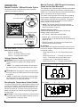
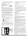
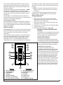
Service Manual
Model Number
BF33STP
BF33DXP
BF39STP
BF39DXP
BF45DXP
UL Part Number
6901811400
6901811500
6901811600
6901811700
6901811900
DXP Model Shown
IMPORTANT SAFETY INFORMATION: Always read this manual first before attempting to service this
fireplace. For your safety, always comply with all warnings and safety instructions contained in this
manual to prevent personal injury or property damage.
Dimplex North America Limited
1367 Industrial Road Cambridge ON Canada N1R 7G8
1-888-346-7539 www.dimplex.com
In keeping with our policy of continuous product development, we reserve the right to make changes without notice.
© 2011 Dimplex North America Limited
REV
PCN
DATE
00
-
3-AUG-11
7400380000R00
TABLE OF CONTENTS
Operation. . . . . . . . . . . . . . . . . . . . . . . . . . . . . . . . . . . . . . . . . . . . . . . . . . . . . . . . . 3
Exploded Parts Diagram. . . . . . . . . . . . . . . . . . . . . . . . . . . . . . . . . . . . . . . . . . 6
Wiring Diagram - STP Models . . . . . . . . . . . . . . . . . . . . . . . . . . . . . . . . . . . . . . 7
Wiring Diagram - DXP Models . . . . . . . . . . . . . . . . . . . . . . . . . . . . . . . . . . . . . . 8
Switch Replacement - Main On/Off Power; Purifier/Heat; Mode Selector. . . . . . . . . . . . . . . .
9
Light Harness Replacement. . . . . . . . . . . . . . . . . . . . . . . . . . . . . . . . . . . . . . . 9
LED Driver Board Replacement - DXP Models Only. . . . . . . . . . . . . . . . 10
Flicker Motor & Rod Replacement. . . . . . . . . . . . . . . . . . . . . . . . . . . . . . . 10
Blower / Motor Replacement . . . . . . . . . . . . . . . . . . . . . . . . . . . . . . . . . . . . . 11
Secured in Wall. . . . . . . . . . . . . . . . . . . . . . . . . . . . . . . . . . . . . . . . . . . . . . . . . . . . . . . . . . . . . . . . . . . . . . . . 11
Removable from Wall . . . . . . . . . . . . . . . . . . . . . . . . . . . . . . . . . . . . . . . . . . . . . . . . . . . . . . . . . . . . . . . . . . . 12
High Temperature Cutout Replacement. . . . . . . . . . . . . . . . . . . . . . . . . . 12
Secured in Wall. . . . . . . . . . . . . . . . . . . . . . . . . . . . . . . . . . . . . . . . . . . . . . . . . . . . . . . . . . . . . . . . . . . . . . . . 12
Removable from Wall . . . . . . . . . . . . . . . . . . . . . . . . . . . . . . . . . . . . . . . . . . . . . . . . . . . . . . . . . . . . . . . . . . . 12
Element Replacement. . . . . . . . . . . . . . . . . . . . . . . . . . . . . . . . . . . . . . . . . . . . 13
Secured in Wall. . . . . . . . . . . . . . . . . . . . . . . . . . . . . . . . . . . . . . . . . . . . . . . . . . . . . . . . . . . . . . . . . . . . . . . . 13
Removable from Wall . . . . . . . . . . . . . . . . . . . . . . . . . . . . . . . . . . . . . . . . . . . . . . . . . . . . . . . . . . . . . . . . . . . 13
Voltage Selector Switch Replacement. . . . . . . . . . . . . . . . . . . . . . . . . . 14
Secured in Wall. . . . . . . . . . . . . . . . . . . . . . . . . . . . . . . . . . . . . . . . . . . . . . . . . . . . . . . . . . . . . . . . . . . . . . . . 14
Removable from Wall . . . . . . . . . . . . . . . . . . . . . . . . . . . . . . . . . . . . . . . . . . . . . . . . . . . . . . . . . . . . . . . . . . . 14
BFRC-KIT Remote Control Receiver Installation/Replacement. . . 15
WRCPF-KIT Wall Controller Installation/Replacement . . . . . . . . . . 15
BF Plug Kit Replacement (BFPLUGE). . . . . . . . . . . . . . . . . . . . . . . . . . . . . . . 16
ASSEMBLY COMPONENT PICTURES. . . . . . . . . . . . . . . . . . . . . . . . . . . . . . . . . . . 17
Troubleshooting Guide. . . . . . . . . . . . . . . . . . . . . . . . . . . . . . . . . . . . . . . . . . 19
Always use a qualified technician or service agency to repair this fireplace.
! NOTE: Procedures and techniques that are considered important enough to emphasize.
CAUTION: Procedures and techniques which, if not carefully followed, will result in damage to the
equipment.
Warning: Procedures and techniques which, if not carefully followed, will expose the user to the
risk of fire, serious injury, or death.
2
www.dimplex.com
Operation
Manual Controls - Without Remote Option
The fireplace can be controlled by the manual switches
located on the fireplace (Figure 1).
Figure 1
Voltage Selector Switch
Over Heat Indicator
Mode Selector Switch
Main On/Off Switch
Main Power Switch - Energizes firebox and flame.
Mode Selector Switch:
Select “o” for flame only
Select “-“ for Purifire™/flame (no heat)
Select “=” for heat/Purifire™/flame
Voltage Selector Switch
arning: Ensure that the incoming power supply
W
voltage matches the setting of the voltage selector
switch.
! NOTE: The voltage selector switch is located inside
the exhaust panel on the top right hand corner (Figure
1).
CAUTION: When changing the voltage selector switch
from 240 volts to 120 volts ensure that the power supply
is turned off.
! NOTE: Carefully insert a flat head screwdriver inside
the exhaust panel to change the switch from 240 volts
(230 position) to 120 volts (115 position).
Resetting the Temperature Cutout Switch
The heater on this fireplace is protected with a safety device
to prevent overheating. Should the heater overheat, a red
light (Figure 1) will be activated and an automatic cut out
will turn the heater off. The heater will re-activate once the
heater has cooled. The overheat cutout will be triggered if
the filter is dirty.
CAUTION: If you need to continuously reset the heater,
disconnect power and call Dimplex customer service at
1-888-DIMPLEX (1-888-346-7539).
Manual Controls - With Remote Accessory
(Hand held or Wall Mounted)
The fireplace with the Remote Option has the same manual
controls with the addition of the Remote Control Receiver
(BFRC-KIT). The Remote Receiver Switch Board which will
work in conjunction with the original controls.
The remote control operation can be adjusted, depending
on the season and desired effects, by toggling the main
mode selector switch built into the fireplace. The position
of the switch will dictate the available functions that the
remote control will cycle through.
! NOTE: The original controls will override all other
settings, both the Mode Selector Switch as well as the
Main On/Off Switch. (Figure 2)
A.Manual Selection Switch
Switches the operation of the fireplace between the
different modes of the fireplace:
• OFF (center): Makes the unit inoperable.
• MANUAL (top): All functions of the fireplace are
controlled by the On and Off buttons as described above
(Figure 2B & C).
• REMOTE (bottom): All functions of the fireplace are
controlled by the Remote Control.
B. Off Button
Pressing this button toggles sequentially through the three
levels of the fireplace. (Only when the selection switch is in
the Manual Position)
• Mode Selector Set at “O”: Only Flame Effect at all 3
levels.
• Mode Selector Set at “--”: Pressing once activates
Level 1 - Flame effect only, two and three times
activates Level 2 - Flame effect and Purifire™.
• Mode Selector Set at “=”: Pressing once activates
Figure 2
Original Version
C
D
F
E
2010 Update
D
B
C
E
B
A
F
3
Level 1 - Flame effect only, twice activates Level 2 Flame effect and Purifire™, three times activates Level
3 - Flame effect, Purifire™ and heat.
C. On Button
Pressing this button at any time will shut the unit off.
D, E & F LED Indicators
Depicts which of the three (3) levels the fireplace is
currently operating at: Level 1 3-
, Level 2 -
or Level
.
Optional Remote Control Operation
The BFRC-KIT is supplied with a radio frequency remote
control. This remote control has a range of approximately
50 feet (15.25 m), it does not have to be pointed at the
fireplace and can pass through most obstacles (including
walls). It is supplied with one of hundreds of independent
frequencies to prevent interference with other units.
! NOTE: Before attempting any operation with the
remote, pull the plastic insulator strip out from between
the remote casing and battery cover (Figure 3).
The remote control operates the fireplace levels
sequentially. The level is increased every time the ON
button on the remote control is pressed. The fireplace can
be turned off at any point by pressing the OFF button on the
remote control.
! NOTE: The Mode Selector Switch on the original
manual controls needs to be set to “=” to have full
functionality of the fireplace. (Figure 2)
:The flame effect is turned on and the first red
Level 1
indicator light is activated.
Level 2
: The flame effect remains on, the Purifire is
activated. (Heater remains off)
: The flame effect remains on, the Purifire is
Level 3
activated and the heater turns on.
Remote Control Initialization/Reprogramming
If the remote control or receiver has been replaced or the
remote does not seem to be operating the fireplace, follow
these steps to initialize/reprogram the remote control and
receiver:
1. Ensure that power is supplied through main service
panel.
Figure 3
On
Button
Off Button
Plastic
Strip
Battery
Cover
Battery must
be recycled or
disposed of
properly. Check with
your Local Authority or
Retailer for recycling
advice in your area.
2. Access the manual controls, (remove the glass doors
if applicable) pull the right hand steel curtain to the
outside of the unit.
3. Locate manual controls.
4. Move the 3-position switch to “Remote”, on newer
models only.
5. Activate the main power switch, the red Level 1
Indicator Light may flash
. (Figure 2-D)
6. Press and hold the On button on the manual controls
(Figure 2-C) for five (5) seconds. The Level 1 Indicator
Light
(Figure 2-D) will then flash for 10 seconds.
7. Within the 10 seconds press the ON button located on
the hand held remote control (Figure 3) or any button
on the wall mounted controller. This will synchronize
the remote control and receiver.
Battery Replacement
To replace the battery:
1. Slide battery cover open on the remote control
(Figure 3).
2. Install one (1) 12-Volt (A23) battery in the battery
holder.
3. Close the battery cover.
Optional Wall Mounted Remote Operation
! NOTE: For button/display references see Figure 4.
1. Room Temperature - Displays current ambient
temperature in the room.
2. Set Temperature - Displays and controls the heater
to the temperature at which the thermostat is currently set
to. Press 8 to lower the thermostat and press 9 to raise
the thermostat. Pressing both 8 and 9 together will toggle
between Celsius and Fahrenheit.
3. Flame Effect Icon - The flame icon will flicker if and
when the Flame Effect is turned on. Press 11 to turn the
Flame Effect on, and press 10 to turn the Flame Effect off.
4. Purifire™ Icon - The display arrows for the Purifire™
will cycle when turned on. Press 13 to turn the Purifire™
function on, and press 12 to turn Purifire™ off.
5.Heat Off Indicator - This function manually overrides
the thermostat control and prevents the fireplace’s heater
from coming on.
To do this, press 8 to decrease Set Temperature to any
temperature below 0o C or 32o F. To reactivate heat from
“HEAT OFF” setting, press 9 to increase the thermostat
Set Temperature. The Set Temperature will be displayed
starting at 21o C (70o F), replacing the “HEAT OFF” icon.
6. Function Lock Indicator - Enabling this function will
lock out the Wall Switch Remote Control so as to prevent
the current settings from being changed. To Enable, press
8, 9, and 10 sequentially. To disengage, press 8, 9 and
10 sequentially again. The Indicator icon will be displayed
when enabled.
7. RF Code Function and Change Procedure - In
4
www.dimplex.com
the event that the Wall Switch Remote Control does not
work properly with the receiver due to interference from
additional wireless signals, this function will allow the RF
code to be changed.
To enable this function, press 9 and 12 together. “CODE”
will appear on the display for five (5) seconds and the
RF code will change automatically. Repeat procedure as
needed to find a code that operates the fireplace without
interference.
Re-initialization of the Wall Switch Remote Control will
need to take place with receiver after a new code has been
activated. See initialization instructions.
14.Low Battery Indicator
When displayed, the indicator will signal that the batteries
are low and should be replaced. To further extend battery
life, the LED backlighting is turned off when the Low Battery
Indicator is displayed.
Other Functions
6 Hour Sleep Timer - This feature ensures all functions are
turned off six hours after any last button has been pressed.
To turn this feature on and off press 9, 11, 10, and 8
sequentially.
When activated, “6 Hr” will display for 5 seconds while the
rest of the LCD remains blank. For the duration of the 6
hour delay, all functions remain working until the 6 hour
time delay runs out. The Set Temperature and Room
Temperature icons will alternately display their settings and
the “6 Hr” icon display. After 6 hours have passed and all
functions are turned off, “6 Hr” will flash until any button is
pressed.
! NOTE: If any button is pressed while this function is
enabled, the 6 hour timer will start over for another 6
hour period.
If / when deactivated (pressing the same sequence of
buttons again), “- Hr” will display for five (5) seconds.
Battery Replacement
To replace the battery:
1. Remove the decora cover from the electrical box
and press the wall remote inward until the push-lock
releases from the mounting box.
1. Remove the wall remote from the mounting box and
slide battery cover open.
2. Install two (2) 1.5V (AAA) battery in the battery holder.
3. Close the battery cover.
4. Reinstall the wall control into mounting box.
Figure 4
6
7
5
1
2
8
9
10
11
12
13
4
Display
1. Room Temperature
2. Set Temperature
3. Flame Effect
4. Purifire™
5.Heat Off Indicator
6. Function Lock Indicator
7. RF Code Function Indicator
3
14
Additional Optional Wall Mounted
Controls
The fireplace can be installed with wall-mounted
controls. These controls include wall switches
and thermostats. (See installation guide for
specific installation details)
A. Wall Mounted Switches
This model may be installed such that a wallmounted switch activates the flame effect and a
wall mounted heater switch activates the heater.
A wall-mounted switch can also be installed to
operate the heater independent of the flame.
B. Wall Mounted Thermostat
This unit may be installed with a wallmounted thermostat which can adjust the heat
temperature to your individual requirements.
Turn the thermostat control clockwise all the way
to turn on the heater. When the room reaches
the desired temperature, turn the thermostat
knob counter clockwise until you hear a click.
Leave in this position to maintain the room
temperature at this setting. For additional heat,
turn the thermostat clockwise until you hear
the click again and the heater will turn on. To
turn the heater off, turn the thermostat counter
clockwise all the way, and/or turn the manual
heater switch on the unit to the OFF position,
“O”.
Operation
8. Set Temperature Down
9. Set Temperature Up
10. Flame Off
11. Flame On
12. Purifire™ Off
13. Purifire™ On
14. Low Battery Indicator
5
Exploded Parts Diagram
7
6
8
18
13
20
2
1
12
4
16
11
9
17
10
20
CATALOGUE NUMBER
UL PART NUMBER
REPLACEMENT PART
1. LOG SET
2. REFLECTOR ROD
3. GROMMET
4. FLICKER MOTOR
6. BLOWER MOTOR
7. HEATER ELEMENT
8. CUTOUT
9. VOLTAGE SELECTOR (6 WIRE)
VOLTAGE SELECTOR (3 WIRE)
10. MAIN ON/OFF SWITCH
11. HEAT SWITCH (--/O ORIGINAL)
3 POSITION PURIFIRE SWITCH
12. PARTIALLY REFLECTIVE GLASS
13. EXTRUSION
14. STEEL CURTAIN
15. STEEL CURTAIN ROD
16. LIGHT HARNESS ASSEMBLY
17. SMART LOG DRIVER
18. PURIFIRE FILTER REPLACEMENT
19. SWING DOOR HARDWARE KIT
20. REMOTE CONTROL KIT
21. WALL MOUNTED REMOTE KIT
22. THERMOSTAT
23. PLUG KIT FOR 120V WALL OUTLET
BF33STP
6901811400
BF33DXP
6901811500
0438200300RP
0439230100RP
5900081000RP
BF39STP
6901811600
0438550200RP
BF39DXP
6901811700
BF45DXP
6901811900
0439070100RP
5900080900RP
8500000600RP
6901811200RP
5300160100RP
2200510100RP
2300200900RP
2300200800RP
2500320100RP
--------- VERIFY 6 WIRE OR 3 WIRE AT TIME OF ORDER ----------2500320200RP
2800070400RP
2800070700RP
2800070800RP
5900161000RP
5900161100RP
5900160600RP
5900160700RP
5900160400RP
NA
0438650100RP
8800240403RP
8800240103RP
8800240203RP
8800250300RP
8800250100RP
8800250200RP
2500370200RP
NA
3000390100RP
NA
3000390100RP
3000390100RP
0439060100RP
9600100100RP
BFRC-KIT
WRCPF-KIT
TS521W (SINGLE POLE), TD522W (DOUBLE POLE)
BFPLUGE
6
www.dimplex.com
Wiring Diagram - STP Models
7
Wiring Diagram - DXP Models
8
www.dimplex.com
Switch Replacement - Main On/Off
Power; Purifier/Heat; Mode Selector
Tools required: Phillips head screwdriver
Flat head screwdriver
! NOTE: Depending on the Modification Level (MOD.)
of your fireplace you will have at least two (or a variation) of
these types of switches: MAIN ON/OFF POWER; PURIFIRE/HEAT; MODE SELECTOR, all of which are located in
the same area in the firebox and can be replaced following
the same instructions below.
Warning: If the fireplace was operating prior to
servicing allow at least 10 minutes for light bulbs and
heating elements to cool off to avoid accidental burning
of skin.
Warning: Disconnect circuit power before attempting any maintenance or cleaning to reduce the risk of
electric shock or damage to persons.
1. Open the steel curtains (remove glass doors if applicable).
2. Remove the 2 screws from the log set retaining plate
along the front of the log set and remove the retaining
plate..
3. Pull the rear edge of the log set forward by grasping
the ember bed by the sides, pull firmly until the rear tab
pops out from under the back ledge, then lift the logs
out. (Figure 5)
! IMPORTANT: Only handle the log-set by the plastic
ember-bed, not the logs themselves.
! NOTE: Log-set fits tightly into firebox. Some force
may be necessary to remove.
4. Disconnect the log set LED wire harness from unit.
(DXP MODELS ONLY)
5. Locate the removable bracket on the lower right side
of the fireplace and remove the 2 mounting screws
located to the left of the switches. (Figure 6)
6. Remove the bracket - turn the back edge toward the
light bulb about 1/2” (12.7mm) then lift straight up.
! NOTE: For Models with Remote Control Receiver
Installed the Plug Connector will have to be disconnected.
Figure 5
Mirror
Ember Bed
Assembly
Back Ledge
Rear Tab
Front Edge
Figure 6
Removable
Bracket
To do this, squeeze the tabs on either side.
7. Reach hand into the opening and locate the switch to
be replaced.
8. Depress the retainer clips on both sides of the switch
and push the switch out of the top.
9. Disconnect the wiring connections noting their original
locations.
! NOTE: Using a flat head screwdriver gently pry between the end of the connector and the switch to release
the wires.
10. Properly orient the new switch and reconnect all of the
wiring connections.
11. Reassemble in the reverse order as above.
! NOTE: When re-inserting the log-set, insert the front
edge first then push the backside of the log-set down until
the rear tab snaps under the back partially reflective glass
ledge and the logs are resting against the partially reflective
glass.
Light Harness Replacement
Tools required: Phillips head screwdriver.
Wire cutters/strippers
Warning: If the fireplace was operating prior to
servicing allow at least 10 minutes for light bulbs and
heating elements to cool off to avoid accidental burning
of skin.
Warning: Disconnect circuit power before attempting any maintenance or cleaning to reduce the risk of
electric shock or damage to persons.
1. Open the steel curtains (remove glass doors if applicable).
2. Remove the 2 screws from the log set retaining plate
along the front of the log set and remove the retaining
plate.
3. Pull the rear edge of the log set forward by grasping
9
the ember bed by the sides, pull firmly until the rear tab
pops out from under the back ledge, then lift the logs
out. (Figure 5)
! IMPORTANT: Only handle the log-set by the plastic
ember-bed, not the logs themselves.
! NOTE: Log-set fits tightly into firebox. Some force
may be necessary to remove.
4. Disconnect the log set LED wire harness from unit.
(DXP MODELS ONLY)
5. Remove all lower light bulbs.
6. Remove the 4 retaining screws on the lower light assembly retaining plate and pull it away from the lower
panel.
7. Cut the blue and white light harness wires from the
old harness at the first socket, which lead inside the
firebox. Strip the ends leading inside the firebox by approximately a ½” (12.7 mm).
8. Remove the socket rings that hold the sockets to the
light assembly retaining plate by unscrewing the rings
counter clockwise.
9. Remove the old sockets and replace with the new
sockets and socket rings.
10. Cut the metal ferrules off the end of the blue and white
wires from the new light harness and strip them by approximately a ½” (12.7mm).
11. Using a wire-nut, connect the 2 matching wire ends
from the old and new harness, matching up the colors
(1-blue to 1-blue / 1-white to 1-white).
! NOTE: Connection to the terminal block can only be
accessed through additional disassembly therefore an additional electrical junction is recommended in the bottom
area.
12. Reassemble in the reverse order as above.
! NOTE: When re-inserting the log-set, insert the front
edge first then push the backside of the log-set down until
the rear tab snaps under the back partially reflective glass
ledge and the logs are resting against the partially reflective
glass.
along the front of the log set and remove the retaining
plate.
3. Pull the rear edge of the log set forward by grasping
the ember bed by the sides (handle the log set only by
the ember bed and not the logs) and pulling firmly until
the rear tab pops out from under the back ledge, then
lift out. (Figure 5)
! IMPORTANT: Only handle the log-set by the plastic
ember-bed, not the logs themselves.
! NOTE: Log-set fits tightly into firebox. Some force
may be necessary to remove.
4. Disconnect the log set LED wire harness from unit.
5. Remove the light assembly retaining plate by removing
4 lower light bulbs and the retaining plate screws. Set
the retaining plate and light bulbs aside.
6. Reach hand into the opening created by removing the
light assembly retaining plate and locate the LED driver
board mounted on the lower right side on the back
panel.
7. Remove the wires attached to the board noting their
original location.
! NOTE: Using a flat head screwdriver gently pry between the end of the connector and the switch to release
the wires.
8. Remove the driver board off the 4 mounting clips (one
on each corner of the board), by squeezing the tips of
the mounting clips with needle nose pliers. Squeeze
them just enough to pull the board off. These clips will
be re-used to secure the new board.
9. Line up the mounting holes on the new board to the
clips and press the new board in place.
10. Install wires on new board in the original configuration.
11. Re-assemble in reverse order as above.
! NOTE: When re-inserting the log-set, insert the front
edge first then push the backside of the log-set down until
the rear tab snaps under the back partially reflective glass
ledge and the logs are resting against the partially reflective
glass.
LED Driver Board Replacement DXP Models Only
Flicker Motor & Rod
Replacement
Tools Required: Phillips head screwdriver
Needle nose pliers
Flat head screwdriver
Warning: If the fireplace was operating prior to
servicing allow at least 10 minutes for light bulbs and
heating elements to cool off to avoid accidental burning
of skin.
Warning: Disconnect circuit power before attempting any maintenance or cleaning to reduce the risk of
electric shock or damage to persons.
1. Open the steel curtains (remove glass doors if applicable).
2. Remove the 2 screws from the log set retaining plate
Tools Required: Phillips head screw driver
¼” (5.5 mm) ratchet/socket or wrench
Warning: If the fireplace was operating prior to
servicing allow at least 10 minutes for light bulbs and
heating elements to cool off to avoid accidental burning
of skin.
Warning: Disconnect circuit power before attempting any maintenance or cleaning to reduce the risk of
electric shock or damage to persons.
1. Open the steel curtains (remove glass doors if applicable).
2. Remove the 2 screws from the log set retaining plate
along the front of the log set and remove the retaining
10
www.dimplex.com
plate.
3. Pull the rear edge of the log set forward by grasping
the ember bed by the sides (handle the log set only by
the ember bed and not the logs) and pulling firmly until
the rear tab pops out from under the back ledge, then
lift out. (Figure 5)
! IMPORTANT: Only handle the log-set by the plastic
ember-bed, not the logs themselves.
! NOTE: Log-set fits tightly into firebox. Some force
may be necessary to remove.
4. Disconnect the log set LED wire harness from unit.
(DXP MODELS ONLY)
5. Remove the 4 lower light bulbs and the light assembly
retaining plate screws. Set the retaining plate and light
bulbs aside.
6. Reach hand into the opening created by removing the
light assembly retaining plate and locate the flicker
assembly, the assembly runs horizontally across the
middle of the unit parallel with the floor (cannot be seen
from the front opening). The assembly is secured with
two brackets, one on either side.
7. Remove the flicker assembly mounting bracket on the
right side (the same side as the controls), using a ¼”
(5.5mm) hex head ratchet/socket or wrench.
8. Remove the flicker rod from the flicker assembly by
pulling the rubber channel section of the rod (located
on the left side of the bracket) away from the flicker
motor.
! NOTE: Once the screw holding the flicker assembly
mounting bracket has been removed you can also turn the
motor and remove the left end of the flicker rod, to remove
the rubber channel. When doing this be careful not to bend
the flicker rod as when the unit is reassembled the flame
may not function properly.
9. Rotate the flicker motor assembly down releasing the
angled mounting tab on the bracket from the rear panel
of the fireplace.
! NOTE: In order for the mounting tab to release from
the rear panel, the flicker assembly mounting bracket
needs to be rotated a complete 90° down. Cutting of the
wire tie wraps may also be required to move wires out of
the way.
10. Disconnect the wiring connections from the terminal
block noting their original locations.
11. Remove the two mounting screws on either side of the
motor and replace with the new one.
12. Properly orient the new motor and reconnect all of the
wiring connections.
13. Reassemble in the reverse order as above.
! NOTE: Be sure to secure the flicker rod to the flicker
motor prior to securing flicker motor assembly bracket to
flame panel. Use wire ties to ensure wires do not come in
contact with moving parts.
! NOTE: When re-inserting the log-set, insert the front
edge first then push the backside of the log-set down until
the rear tab snaps under the back partially reflective glass
ledge and the logs are resting against the partially reflective
glass.
Blower / Motor Replacement
Secured in Wall
Tools Required: Philips head screwdriver
Flat head screwdriver
Needle nose pliers
Warning: If the fireplace was operating prior to
servicing allow at least 10 minutes for light bulbs and
heating elements to cool off to avoid accidental burning
of skin.
Warning: Disconnect circuit power before attempting any maintenance or cleaning to reduce the risk of
electric shock or damage to persons.
1. Open the steel curtains (remove glass doors if applicable).
2. Remove the 2 screws from the log set retaining plate
along the front of the log set and remove the retaining
plate.
3. Pull the rear edge of the log set forward by grasping
the ember bed by the sides, pull firmly until the rear tab
pops out from under the back ledge, then lift the logs
out. (Figure 5)
! IMPORTANT: Only handle the log-set by the plastic
ember-bed, not the logs themselves.
! NOTE: Log-set fits tightly into firebox. Some force
may be necessary to remove.
4. Disconnect the log set LED wire harness from unit.
(DXP MODELS ONLY)
5. Release the steel curtains from the side panels by
opening the retainers on the sides of the fireplace using
needle nose pliers.
6. Remove the steel curtains by lifting up on the curtain
mounting rod releasing it from the side mounting tab,
and pulling out.
7. Remove the 2 filter retaining screws and remove the
filter and retaining plate.
8. Remove the 10 mounting screws from inside the firebox that secures the interior top panel and remove the
heater cover.
9. Remove the 3 heater assembly mounting screws from
underneath the top panel along the front.
10. Lower the heater assembly so that the 3 support tabs,
in the top panel, can be easily released.
11. Remove wiring connections from blower motor noting
their original locations.
! NOTE: Using a flat head screwdriver gently pry
between the end of the connector and the blower/motor to
release the wires.
12. Remove the 6 blower motor assembly screws and set
aside blower motor assembly.
11
13. Properly orient the replacement blower assembly and
reconnect all of the wiring connections in their original
locations.
14. Reassemble in the reverse order as above.
! NOTE: When re-inserting the log-set, insert the front
edge first then push the backside of the log-set down until
the rear tab snaps under the back partially reflective glass
ledge and the logs are resting against the partially reflective
glass.
Removable from Wall
Tools Required: Philips head screwdriver
Flat head screwdriver
Warning: If the fireplace was operating prior to
servicing allow at least 10 minutes for light bulbs and
heating elements to cool off to avoid accidental burning
of skin.
Warning: Disconnect circuit power before attempting any maintenance or cleaning to reduce the risk of
electric shock or damage to persons.
1. Remove unit from installed wall (remove trim surround,
if applicable).
2. Remove the outer top panel mounting screws, (3 left
side, 3 back, 3 right side). Lift the panel off the firebox
and position heater assembly upright being careful not
to damage any wires.
3. Remove the 3 heater assembly mounting screws from
underneath the top panel along the front.
4. Lower the heater assembly so that the 3 support tabs,
in the top panel, can be easily released.
5. Remove the 6 blower motor assembly screws and set
aside blower motor assembly.
6. Remove the wires attached to the blower/motor noting
their original location.
! NOTE: Using a flat head screwdriver gently pry
between the end of the connector and the blower/motor to
release the wires.
7. Properly orient the replacement blower assembly and
reconnect all of the wiring connections in their original
locations.
8. Reassemble in the reverse order as above.
High Temperature Cutout
Replacement
Secured in Wall
Tools Required: Philips head screwdriver
Needle nose pliers
Warning: If the fireplace was operating prior to
servicing allow at least 10 minutes for light bulbs and
heating elements to cool off to avoid accidental burning
of skin.
Warning: Disconnect circuit power before attempting any maintenance or cleaning to reduce the risk of
electric shock or damage to persons.
1. Open the steel curtains (remove glass doors if applicable).
2. Remove the 2 screws from the log set retaining plate
along the front of the log set and remove the retaining
plate.
3. Pull the rear edge of the log set forward by grasping
the ember bed by the sides, pull firmly until the rear tab
pops out from under the back ledge, then lift the logs
out. (Figure 5)
! IMPORTANT: Only handle the log-set by the plastic
ember-bed, not the logs themselves.
! NOTE: Log-set fits tightly into firebox. Some force
may be necessary to remove.
4. Disconnect the log set LED wire harness from unit.
(DXP MODELS ONLY)
5. Release the steel curtains from the side panels by
opening the retainers on the sides of the fireplace using
needle nose pliers.
6. Remove the steel curtains by lifting up on the curtain
mounting-rod releasing it from the side mounting tab,
and pulling out.
7. Remove the 2 filter retaining screws and remove the
filter and retaining plate.
8. Remove the 10 mounting screws from inside the firebox that secures the interior top panel and remove the
heater cover.
9. Remove the 3 heater assembly mounting screws from
underneath the top panel along the front.
10. Lower the heater assembly so that the 3 support tabs,
in the top panel, can be easily released.
11. Remove temperature limit switch screw from heater
bracket assembly and disconnect the temperature limit
switch wire from heater element and from the wire connectors, noting their original location.
12. Properly orient the new temperature limit switch and
secure it to the heater bracket assembly with the small
screw from the original cutout.
13. Reconnect the wires in their original locations.
14. Reassemble in the reverse order as above.
Warning: Ensure wires do not come in contact with
moving parts by securing wires in tie wraps.
! NOTE: When re-inserting the log-set, insert the front
edge first then push the backside of the log-set down until
the rear tab snaps under the back partially reflective glass
ledge and the logs are resting against the partially reflective
glass.
Removable from Wall
Tools Required: Philips head screwdriver
Warning: If the fireplace was operating prior to
servicing allow at least 10 minutes for light bulbs and
heating elements to cool off to avoid accidental burning
of skin.
Warning: Disconnect circuit power before attempt-
12
www.dimplex.com
ing any maintenance or cleaning to reduce the risk of
electric shock or damage to persons.
1. Remove unit from installed wall (remove trim surround,
if applicable).
2. Remove the outer top panel mounting screws, (3 left
side, 3 back, 3 right side). Lift the panel off the firebox
and position heater assembly upright being careful not
to damage any wires.
3. Remove the 3 heater assembly mounting screws from
underneath the top panel along the front.
4. Lower the heater assembly so that the 3 support tabs,
in the top panel, can be easily released.
5. Remove temperature limit switch screw from heater
bracket assembly and disconnect the temperature limit
switch wire from heater element and from the wire connectors, noting their original location.
! NOTE: To reconnect temperature limit switch, cut and
strip the long end of the cutout wire, and wire connect to
existing cutout wire closest to blower motor.
6. Properly orient the new temperature limit switch and
secure to heater bracket assembly.
7. Reconnect the wires in their original locations.
8. Reassemble in the reverse order as above.
Warning: Ensure wires do not come in contact with
moving parts by securing wires in tie wraps.
Element Replacement
Secured in Wall
Tools Required: Philips head screwdriver
⅜” Hex head socket or ratchet
Needle nose pliers
Warning: If the fireplace was operating prior to
servicing allow at least 10 minutes for light bulbs and
heating elements to cool off to avoid accidental burning
of skin.
Warning: Disconnect circuit power before attempting any maintenance or cleaning to reduce the risk of
electric shock or damage to persons.
! NOTE: The fireplace is equipped with two heating
elements. The same removal and installation instructions
apply to both elements.
1. Open the steel curtains (remove glass doors if applicable).
2. Remove the 2 screws from the log set retaining plate
along the front of the log set and remove the retaining
plate.
3. Pull the rear edge of the log set forward by grasping
the ember bed by the sides, pull firmly until the rear tab
pops out from under the back ledge, then lift the logs
out. (Figure 5)
! IMPORTANT: Only handle the log-set by the plastic
ember-bed, not the logs themselves.
! NOTE: Log-set fits tightly into firebox. Some force
may be necessary to remove.
4. Disconnect the log set LED wire harness from unit.
(DXP MODELS ONLY)
5. Release the steel curtains from the side panels by
opening the retainers on the sides of the fireplace using
needle nose pliers.
6. Remove the steel curtains by lifting up on the curtain
mounting rod releasing it from the side mounting tab,
and pulling out.
7. Remove the 2 filter retaining screws and remove the
filter and retaining plate.
8. Remove the 10 mounting screws from inside the firebox that secures the interior top panel and remove the
heater cover.
9. Locate the elements mounted to the top cover, pull the
sheathing back and disconnect the connections noting
their original locations.
10. Remove the 2 element cover hex head screws on the
right using a ⅜” Hex head socket.
11. Remove the 3 remaining element cover mounting
screws on the left and remove element.
12. Properly orient the replacement element and reconnect
all of the wiring connections in their original locations.
13. Reassemble in the reverse order as above.
! NOTE: When re-inserting the log-set, insert the front
edge first then push the backside of the log-set down until
the rear tab snaps under the back partially reflective glass
ledge and the logs are resting against the partially reflective
glass.
Removable from Wall
Tools Required: Philips head screwdriver
⅜” Hex head socket or ratchet
Needle nose pliers
Warning: If the fireplace was operating prior to
servicing allow at least 10 minutes for light bulbs and
heating elements to cool off to avoid accidental burning
of skin.
Warning: Disconnect circuit power before attempting any maintenance or cleaning to reduce the risk of
electric shock or damage to persons.
! NOTE: The fireplace is equipped with two heating
elements. The same removal and installation instructions
apply to both elements.
1. Remove unit from installed wall. (Remove trim surround
if applicable).
2. Remove the outer top panel mounting screws, (3-left
side, 3-back, 3-right side). Lift the panel off the firebox
and position heater assembly upright being careful not
to damage any wires.
3. Locate the elements mounted to the top cover, pull
back the sheathing and disconnect the connections
noting their original locations.
4. Remove the 2 element cover hex head screws on the
right using a ⅜” Hex head socket.
13
5. Remove the 3 remaining element cover mounting
screws on the left and remove element.
6. Properly orient the replacement element and reconnect
all of the wiring connections in their original locations.
7. Reassemble in the reverse order as above.
Voltage Selector Switch
Replacement
Secured in Wall
Tools Required: Philips head screwdriver
Flat head screwdriver
Wire cutters/strippers
Needle nose pliers
Warning: If the fireplace was operating prior to
servicing allow at least 10 minutes for light bulbs and
heating elements to cool off to avoid accidental burning
of skin.
Warning: Disconnect circuit power before attempting any maintenance or cleaning to reduce the risk of
electric shock or damage to persons.
1. Remove the log grate retaining screws and remove the
log grate.
2. Pull the rear edge of the log set forward by grasping
the ember bed by the sides (handle the log set only by
the ember bed and not the logs) and pulling firmly until
the rear tab pops out from under the back ledge, then
lift out. (Figure 5)
! IMPORTANT: Only handle the log-set by the plastic
ember-bed, not the logs themselves.
! NOTE: Log-set fits tightly into firebox. Some force
may be necessary to remove.
3. Disconnect the log set LED wire harness from unit.
(DXP MODELS ONLY)
4. Release the steel curtains from the side panels by
opening the retainers on the sides of the fireplace using
needle nose pliers.
5. Remove the steel curtains by lifting up on the curtain
mounting-rod releasing it from the side mounting tab,
and pulling out.
6. Remove the 2 filter retaining screws and remove the
filter and retaining plate.
7. Remove the 10 mounting screws from inside the firebox that secures the interior top panel and remove the
heater cover.
8. Remove the 3 heater assembly mounting screws from
underneath the top panel along the front.
9. Lower the heater assembly so that the 3 support tabs,
in the top panel, can be easily released.
10. Locate the voltage selector switch inside the exhaust
panel on the top right hand corner, and cut the wire tie
wraps securing the voltage selector switch wires.
11. Remove the voltage selector wire connections from the
switch noting their original locations.
! NOTE: Using a flat head screwdriver gently pry be-
tween the end of the connector and the switch to release
the wires.
12. Depress the retainer clips on the rear of the voltage
selector switch and push the switch out of the front vent
panel.
13. Properly orient the new switch and reconnect all of the
wiring connections.
Warning: Ensure wires do not come in contact with
moving parts by securing wires in wiring tie wraps.
14. Reassemble in the reverse order as above.
! NOTE: When re-inserting the log-set, insert the front
edge first then push the backside of the log-set down until
the rear tab snaps under the back partially reflective glass
ledge and the logs are resting against the partially reflective
glass.
Removable from Wall
Tools Required: Philips head screwdriver
Wire cutters/strippers
Flat head screwdriver
Needle nose pliers
Warning: If the fireplace was operating prior to
servicing allow at least 10 minutes for light bulbs and
heating elements to cool off to avoid accidental burning
of skin.
Warning: Disconnect circuit power before attempting any maintenance or cleaning to reduce the risk of
electric shock or damage to persons.
1. Remove unit from installed wall (remove trim surround,
if applicable).
2. Remove the outer top panel mounting screws, (3-left
side, 3-back, 3-right side). Lift the panel off the firebox
and position heater assembly upright being careful not
to damage any wires.
3. Locate the voltage selector switch inside the exhaust
panel on the top right hand corner, and cut the wire tie
wraps securing the voltage selector switch wires.
4. Disconnect voltage selector switch wire connections
from heater elements noting their original locations.
! NOTE: Using a flat head screwdriver gently pry between the end of the connector and the switch to release
the wires.
5. Depress the retainer clips on the rear of the voltage
selector switch and push the switch out of the front vent
panel.
6. Properly orient the new switch and reconnect all of the
wiring connections.
Warning: Ensure wires do not come in contact with
moving parts by securing wires in wiring tie wraps.
7. Reassemble in the reverse order as above.
14
www.dimplex.com
BFRC-KIT Remote Control
Receiver Installation/
Replacement
Tools Required: Philips head screwdriver
Warning: If the fireplace was operating prior to
servicing allow at least 10 minutes for light bulbs and
heating elements to cool off to avoid accidental burning
of skin.
Warning: Disconnect circuit power before attempting any maintenance or cleaning to reduce the risk of
electric shock or damage to persons.
1. Open the steel curtains (remove glass doors if applicable).
2. Remove the log retaining plate/grate located on the
lower panel along the front base of the log set, by removing the screws that secure the plate to the firebox.
3. Pull the rear edge of the log set forward by grasping
the ember bed by the sides (handle the log set only by
the ember bed and not the logs) and pulling firmly until
the rear tab pops out from under the back ledge, then
lift out. (Figure 5)
! IMPORTANT: Only handle the log-set by the plastic
ember-bed, not the logs themselves.
! NOTE: Log-set fits tightly into firebox. Some force
may be necessary to remove.
4. Disconnect the log set LED wire harness from unit.
(DXP MODELS ONLY)
5. Locate the removable bracket on the lower right side
of the fireplace and remove the 2 mounting screws
located to the left of the manual switches.
6. Remove the bracket - turn the back edge toward the
light bulb about 1/2” (12.7mm) then lift straight up.
7. Depressing both tabs on either side of the quick connect plug and unplug it from the unit.
8. Locate the plug connector on the new assembly.
9. Position the antenna wire so that it is under the new
bracket, plug in and install the bracket into position.
! NOTE: The plug only will fit in one way so it may need
to be rotated to be inserted.
10. Locate and install the two screws on the new remote
control panel.
11. Replace the log by inserting front edge and pushing
the back down until rear tab snaps under back ledge
(Figure 5) and the logs are resting against partially
reflective glass.
! NOTE: When re-inserting the log-set, insert the front
edge first then push the backside of the log-set down until
the rear tab snaps under the back partially reflective glass
ledge and the logs are resting against the partially reflective
glass.
12. Replace log grate, using two screws previously removed.
13. Initialize the remote control to the new receiver installed
in the fireplace as per the instructions included in the
remote packaging.
WRCPF-KIT Wall Controller
Installation/Replacement
Tools Required: Philips head screwdriver
Warning: If the fireplace was operating prior to
servicing allow at least 10 minutes for light bulbs and
heating elements to cool off to avoid accidental burning
of skin.
Warning: Disconnect circuit power before attempting any maintenance or cleaning to reduce the risk of
electric shock or damage to persons.
1. Open the steel curtains (remove glass doors if applicable).
2. Remove the log retaining plate/grate located on the
lower panel along the front base of the log set, by removing the screws that secure the plate to the firebox.
3. Pull the rear edge of the log set forward by grasping
the ember bed by the sides (handle the log set only by
the ember bed and not the logs) and pulling firmly until
the rear tab pops out from under the back ledge, then
lift out. (Figure 5)
! IMPORTANT: Only handle the log-set by the plastic
ember-bed, not the logs themselves.
! NOTE: Log-set fits tightly into firebox. Some force
may be necessary to remove.
4. Disconnect the log set LED wire harness from unit.
(DXP MODELS ONLY)
5. Locate the removable bracket on the lower right side
of the fireplace and remove the 2 mounting screws
located to the left of the switches.
6. Remove the bracket - turn the back edge toward the
light bulb about 1/2” (12.7mm) then lift straight up.
7. Depressing both tabs on either side of the plug connector unplug it from the unit.
8. Locate the plug connector on the new assembly.
9. Position the antenna wire so that it is under the new
bracket, plug in and install the bracket into position.
10. Locate and install the two screws on the remote control
panel.
11. Replace the log by inserting front edge and pushing
the back down until rear tab snaps under back ledge
(Figure 5) and the logs are resting against partially
reflective glass.
! NOTE: When re-inserting the log-set, insert the front
edge first then push the backside of the log-set down until
the rear tab snaps under the back partially reflective glass
ledge and the logs are resting against the partially reflective
glass.
12. Replace log grate, using two screws previously removed.
13. Mount the wall controller within a standard electrical
device box, located within 50ft (15m) of the firebox and
15
install cover plate. (See included instructions for electrical installation and requirements.)
14. Initialize the remote control to the new receiver installed
in the fireplace as per the instructions included in the
remote packaging.
BF Plug Kit Replacement
(BFPLUGE)
!
NOTE: This accessory is only for 110/120V use only.
Tools Required: Philips head screwdriver
Warning: If the fireplace was operating prior to
servicing allow at least 10 minutes for light bulbs and
heating elements to cool off to avoid accidental burning
of skin.
Warning: Disconnect circuit power before attempting any maintenance or cleaning to reduce the risk of
electric shock or damage to persons.
1. Unplug the fireplace from the wall outlet.
2. Locate the voltage selector switch on the top corner
of the fireplace and make sure the switch is set to 115
V. (The switch should already be set to 115V from the
original installation of this optional accessory cord.
Power cord/Plugs are only approved for operation on
the BF33, BF39 or BF45 in 110 – 120 volt application.
Fireplace must be removable from the wall for access
when a plug kit is being used).
3. Loosen the screw securing the junction box cover on
the lower right hand side panel toward the back and
remove the cover.
4. Pull out the four wires marked L1, L2, N, and G.
5. Replace the black L1 wire from the unit to the nonribbed L1 wire from the power cord, connect the red L2
and white N wires from the unit to the ribbed or neutral
from the power cord. (Wide blade on the plug is the
neutral side of the power cord), connect a wire connector to the green ground wire from the unit.
6. Ensure that all wire connections are tight.
7. Re-Install the junction box cover and tighten the screw.
8. Plug the fireplace back into the outlet for power.
9. If fireplace has a BFRC-KIT (remote control kit) used
to operate the unit, the remote control may need to be
re-synchronized to the fireplace once power has been
restored to the fireplace.
16
www.dimplex.com
ASSEMBLY COMPONENT PICTURES
Left Element Connections
Right Element and Blower Connections
Elements, Blower and Voltage Selector
Connections
High Temperature Cutout
Interior Bottom View of Voltage Selector
Switch and Over Temperature Light
Exterior View of Voltage Selector Switch and
Over Temperature Light
17
LED Driver Board
Uninstalled Flicker Motor and Terminal block
Rear View Light Panel/Harness
Flicker Rod and Flicker Motor Attachment
Manual Controls
with Remote Control Bracket Removed
Manual Controls Interior Side View
“Dummy Plug”
(Factory Installed)
No Remote
Operation
18
www.dimplex.com
Troubleshooting Guide
Problem
Cause
Solution
General
Circuit breaker trips or fuse
blows when unit is turned on
Short in unit wiring.
Trace wiring in unit.
Improper circuit current rating
Verify unit is installed on a dedicated 15 amp circuit.
Unit turns on or off by itself
Remote Control has a similar frequency
to other remotes in the area.
Replace Remote Control
Wall Mounted remote control has a
similar frequency to other remotes in the
area.
Change the RF frequency of wall mounted remote and
reinitialize. (Instructions found in Operation section)
Radio frequency disturbance from outside sources.
Replace remote control and Remote Control Receiver
Kit, where necessary.
Power cord gets warm (if using
BFPLUGE kit)
Defective Remote Control Receiver Kit
Replace Remote Control Receiver Kit
Normal Operation
The power cord may get slightly warm to the touch
when the heater is on
Defective power cord
Replace power cord if cord gets hot to the touch.
Improper operation
Refer to Operation Section
No incoming voltage from the electrical
wall socket/Breaker Panel
Check Fuse/Breaker Panel
Loose wiring
Check wiring connections
Defective On/Off Switch
Replace On/Off Switch
Defective 3-Position Switch
Replace 3-Position Switch
Improper operation
Refer to Operation Section
Remote control not initialized to fireplace
Initialize the remote control
Defective remote control
Install new battery into the remote control. Reinitilize
remote where necessary
Appearance
Fireplace does not turn on
Manually
Fireplace does not turn on with
remote control (if applicable)
Replace Remote Control and reinitialize
Fireplace does not turn on with
Wall Mounted remote (if applicable)
Defective Remote Control Receiver Kit
Replace Remote Control Receiver Kit
Improper operation
Refer to Operation Section
Remote control not initialized to fireplace
Initialize the remote control
Defective remote control
Install new battery into the wall mounted remote control. Reinitialize remote where necessary
Replace Remote Control Receiver Kit where necessary
Flame Frozen
Defective flicker motor
Replace flicker motor
Loose wiring
Check wiring connections
Burnt light bulbs
Replace light bulbs
Loose wiring
Check wiring connections
Defective light harness
Replace light harness
Log set dim, ember bed not
glowing
Burnt light bulbs
Replace light bulbs
Log set not glowing/pulsing
(DXP Models Only)
Loose wiring harness
Check wiring connections
Defective LED Driver Board
LED Driver Board
Defective log set
Replace log set
Flame Shudder
Defective flicker motor
Replace flicker motor
Light leaking around the log set
Log set not positioned properly
Check log set for proper fit
Flame not bright or flame not
visible
19
Problem
Cause
Solution
Heater
Heater is not turning On
Improper operation
Refer to Operation Section
Improper Installation of Thermostat/Wall
Controls
Refer to Installation Guide
Loose wiring
Trace wiring in unit
Defective 3-Position Switch
Replace 3-Position Switch
Defective Remote Control Receiver Kit (if Replace Remote Control Receiver Kit
applicable)
Heater is not turning Off
Improper operation of unit
Refer to Operation Section
Improper operation of Thermostat/Wall
Controls (if applicable)
Refer to Thermostat/Wall Control Operation Guide
Defective heater on/off switch
Replace heater on/off switch
Defective heater assembly
Replace heater assembly
Build up of dirt/dust in heater assembly
Ensure that exterior intake louvers and firebox cavity
are free of dirt/dust.
Defective Heater Assembly
Replace Heater motor (if not running when heat is activated) or Heater Elements (if motor is running but heat
is not coming out)
Heater emits an odor
Normal Operation
Normal operation is when the heater emits an odor
for a brief period after the heater is initially turned on.
The heater is burning off any dust accumulated during
manufacturing or operation.
Defective heater assembly
Replace heater assembly
Heater fan turns on but heater
lacks heat
Improper operation
Refer to Operation Section
Loose wiring
Trace wiring in unit
Defective Heater Assembly
Replace Heater motor (if not running when heat is
activated)
Heater is turning off after a
couple of minutes of operation
Heater Elements (if motor is running but heat is not
coming out)
Heating element is glowing red
Heater fan runs continuously
Normal Operation
Small glowing sections of the element are considered
normal.
Defective heater element
If larger glowing sections are causing the heater to trip
the thermal cutout, unplug unit, discontinue use and
replace heater elements
Defective heater on/off switch
Replace heater on/off switch
Defective Thermostat/Wall Controls
Replace Thermostat/Wall Controls
Dirty blower assembly
Ensure that exterior intake louvers and firebox cavity
are free of dirt/dust.
Defective Heater motor
Replace heater motor
Moving flicker rod hitting or rubbing
against internal components
Ensure rod is straight and mounted properly in the
bracket, spinning freely away from other components.
Replace if necessary.
Defective flicker motor
Replace flicker motor
Noise
Excessive noise with the heater
on
Grinding or excessive noise with
the heater off
20
www.dimplex.com