1
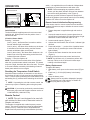
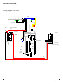
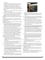
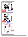
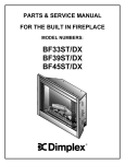
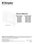
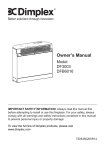
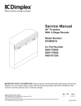
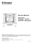
Service Manual
Model Number:
BF362SD
BF392SD
UL Part Number
6901550159
IMPORTANT SAFETY INFORMATION: Always read this manual first before attempting to service this
fireplace. For your safety, always comply with all warnings and safety instructions contained in this
manual to prevent personal injury or property damage.
Dimplex North America Limited
1367 Industrial Road Cambridge ON Canada N1R 7G8
1-888-346-7539 www.dimplex.com
In keeping with our policy of continuous product development, we reserve the right to make changes without notice.
© 2011 Dimplex North America Limited
7400150000R02
TABLE OF CONTENTS
Operation. . . . . . . . . . . . . . . . . . . . . . . . . . . . . . . . . . . . . . . . . . . . . . . . . . . . . . . . . . . 3
Maintenance. . . . . . . . . . . . . . . . . . . . . . . . . . . . . . . . . . . . . . . . . . . . . . . . . . . . . . . . . 4
Exploded Parts Diagram. . . . . . . . . . . . . . . . . . . . . . . . . . . . . . . . . . . . . . . . . . . . . . . 5
Replacement Parts . . . . . . . . . . . . . . . . . . . . . . . . . . . . . . . . . . . . . . . . . . . . . . . . . . . 5
Wiring Diagram . . . . . . . . . . . . . . . . . . . . . . . . . . . . . . . . . . . . . . . . . . . . . . . . . . . . . . 6
Switch Replacements. . . . . . . . . . . . . . . . . . . . . . . . . . . . . . . . . . . . . . . . . . . . . . . . . 8
On/Off & 3-Position Heater Switches. . . . . . . . . . . . . . . . . . . . . . . . . . . . . . . . . . . . . . . . . . . . . . . . . . . . . . . . 8
Flicker Motor/ Flicker Rod Replacement. . . . . . . . . . . . . . . . . . . . . . . . . . . . . . . . . . 8
Heater Assembly Replacement . . . . . . . . . . . . . . . . . . . . . . . . . . . . . . . . . . . . . . . . . 9
Remote Control Receiver Replacement . . . . . . . . . . . . . . . . . . . . . . . . . . . . . . . . . . 9
Troubleshooting Guide. . . . . . . . . . . . . . . . . . . . . . . . . . . . . . . . . . . . . . . . . . . . . . . 12
Always use a qualified technician or service agency to repair this fireplace.
! NOTE: Procedures and techniques that are considered important enough to emphasize.
CAUTION: Procedures and techniques which, if not carefully followed, will result in damage to the
equipment.
Warning: Procedures and techniques which, if not carefully followed, will expose the user to the
risk of fire, serious injury, or death.
2
www.dimplex.com
Operation
Figure 1
Manual Controls
3-Position
Switch
On/Off
Switch
Level 3 Indicator
Level 2 Indicator
Level 1 Indicator
Manual Controls
On/Off Switch
The On/Off Switch supplies power to the remote control
receiving unit. When placed in the On position Level 1
indicator will flash.
3-Position Heater Switch
Pressing “-” activates:
Level 1 (once) - the flame effect is turned on and the
first red indicator light is activated;
Level 2 (twice) - the flame effect remains on, the heater
is activated to the low heat setting, and the first and
second red indicator lights are activated;
Level 3 (three times) - the flame effect remains on, the
heater is set to the high heat setting, and all three red
indicator lights are activated.
Pressing “=” turns the fireplace off.
NOTE: Hot air will blow from both sides of the fireplace
when the 3-position heater switch is activated. The heater
may emit a slight, harmless odor when first used. This odor
is a normal condition caused by initial heating of internal
heater parts and will not occur again.
Resetting the Temperature Cutoff Switch
Should the heater overheat, an automatic cut out will turn
the fireplace off and it will not come back on without being
reset. It can be reset by switching the On/Off Switch to Off
and waiting five (5) minutes before switching the unit back
on.
! NOTE: If operating the unit with a remote control, the
remote may require re-initializing after turning the power
off.
CAUTION: If you need to continuously reset the heater,
disconnect power and call Dimplex customer service at
1-888-DIMPLEX (1-888-346-7539).
Remote Control
! NOTE: This unit is not designed to be used with
wall switches for flame control, thermostat control or
Dimplex wall setters.
The fireplace is supplied with a radio frequency remote
control. This remote control has a range of approximately
50 feet (15.25 m), it does not have to be pointed at the
fireplace and can pass through most obstacles (including
walls). It is supplied with one of hundreds of independent
frequencies to prevent interference with other units.
! NOTE: Before attempting any operation with the
remote, pull the plastic insulator strip out from between
the remote casing and battery cover (Figure 2).
To operate, push the ON button sequence through the 3
levels of the fireplace (see manual controls for more detail),
push the OFF button to turn the fireplace off.
Remote Control Initialization/Reprogramming
If the remote control or remote control receiver has been
replaced, follow these steps to initialize the remote control
and receiver:
1. Ensure that power is supplied through main service
panel.
2. Access the manual controls, (remove glass doors or
pull grill down if applicable) pull right hand edge of right
hand steel curtain towards the center of unit.
3. Locate manual controls. (Figure 1)
4. Activate the On/Off switch, the red level 1 indicator light
will flash.
5. Press and hold the “ - “ portion of the 3-position heater
switch for five (5) seconds (the second red indicator
light will flash).
6. Press the On button located on the remote control.
(Figure 2)
This will synchronize the remote control and receiver.
! NOTE: You will have only 10 seconds to perform this
last step. Failure to do so will result in these steps
needing to be followed again.
Battery Replacement
To replace the battery:
1. Slide battery cover open on the remote control (Figure
2).
2. Install one (1) 12-Volt (A23) battery in the battery
holder.
3. Close the battery cover
Battery must be recycled or disposed of properly.
Check with your Local Authority or Retailer for
recycling advice in your area.
Figure 2
On
Button
Off Button
Plastic
Strip
Battery
Cover
3
Maintenance
arning: Disconnect all power coming to fireplace at
W
main service panel before attempting any maintenance
or cleaning to reduce risk of fire, electric shock or
damage to persons.
Warning: If the fireplace was operating prior to
servicing allow at least 10 minutes for light bulbs and
heating elements to cool off to avoid accidental burning
of skin.
Light Bulb Replacement
Light bulbs need to be replaced when you notice a dark
section of the flame of when the clarity is reduced. There
are four bulbs under the log set which generate the flames
and embers.
Helpful Hints: It is a good idea to replace all light bulbs
at one time if they are close to the end of their rated life.
Group replacement will reduce the number of times you
need to open the unit to replace light bulbs. Long life
bulbs are recommended to reduce the frequency of bulb
changes.
Bulb Requirements: Quantity of 4 clear chandelier or
candelabra bulbs with an E-12 (small) socket base, 60 watt
rating. Example: GE 60BC or Philips 60CTC.
Do not exceed 60 Watts per bulb.
Tool Requirements: Philips Screw Driver
1. Open steel curtain (remove glass doors if applicable).
The bulbs can be accessed from either side of the
fireplace.
2. Remove two screws on log bracket and remove log
plate (Figure 3).
3. Pull the rear edge of the log set forward by grasping
the ember bed by the sides, pull firmly until the rear tab
pops out from under the back ledge, then lift the logs
out. (Figure 4)
! IMPORTANT: Only handle the log-set by the plastic
ember-bed, not the logs themselves.
! NOTE: Log-set fits tightly into firebox. Some force may
be necessary to remove.
4. Examine the bulbs to determine which bulbs require
replacement.
5. Remove the flicker rod. Begin by removing the plastic
grommet, which holds the end of the rod in the left
bracket. Grasp and turn it ¼ turn, releasing it from the
slot in the bracket, and then lift it out of the bracket.
6. The motor side of the rod may be attached to the motor
in one of two ways:
• Secured with a spring - attach needle nose pliers to
the spring on the motor shaft and pull while rotating in
the same direction of the spring winding.
• Secured with a rubber gasket - pull and twist the gasket away from the motor simultaneously until it comes
off the motor shaft.
CAUTION: Ensure that the flicker rod does not get
bent during removal and re-connecting, ensure the rod is
straight when replaced, otherwise, it may cause excessive
noise during operation.
! NOTE: To replace the flicker rod that uses a spring,
attach needle nose pliers to the flicker rod spring and push
onto the flicker motor shaft while rotating in the opposite
direction of the spring winding.
7. Unscrew bulbs counter clockwise.
8. Insert new bulbs.
9. Reassemble in the reverse order as above.
! NOTE: To replace the log set insert the front edge,
pushing back down until the rear tab snaps under the back
ledge and the logs are resting against the partially reflective
glass.
Partially Reflective Glass Cleaning
The partially reflective glass is cleaned in the factory during
the assembly operation. During shipment, installation,
handling, etc., the partially reflective glass surface may
collect dust particles; these can be removed by buffing
lightly with a clean dry cloth.
To remove fingerprints or other marks, the partially
reflective glass can be cleaned with a damp cloth using
good quality household glass cleaner. The partially
reflective glass should be completely dried with a lint free
cloth or paper towel.
CAUTION: Do not use abrasive cleaners on partially
reflective glass surface or spray liquids directly onto any
surface.
Figure 3
SCREWS
Figure 4
Mirror
Ember Bed
Assembly
Back Ledge
Rear Tab
Front Edge
4
www.dimplex.com
Exploded Parts Diagram
4
10
7
12
9
4
9
1
1
12
11
8
5
6
11
13
3
2
Replacement Parts
1.
2.
3.
4.
5.
6.
7.
LOGSET . . . . . . . . . . . . . . . . . . . . . . . .
FLICKER MOTOR. . . . . . . . . . . . . . . . .
FLICKER ROD . . . . . . . . . . . . . . . . . . .
HEATER ASSEMBLY . . . . . . . . . . . . .
3-POSITION HEATER SWITCH . . . . .
ON/OFF SWITCH . . . . . . . . . . . . . . . . .
REMOTE CONTROL . . . . . . . . . . . . . .
0438550300RP
2000140300RP
5900080800RP
2000230200RP
2800070500RP
2800070700RP
3000370600RP
8. REMOTE CONTROL RECEIVER
MOD 0-B. . . . . . . . . . . . . . . . . . . . . .
MOD C . . . . . . . . . . . . . . . . . . . . . . .
9. PARTIALLY REFLECTIVE GLASS. . . .
10. GLASS SUPPORT STRIP . . . . . . . . . .
11. MESH CURTAIN. . . . . . . . . . . . . . . . . .
12. CURTAIN ROD . . . . . . . . . . . . . . . . . . .
13. LIGHT SOCKETS WITH HARNESS. . .
3000430800RP
9600480100RP
5900160600RP
0438290100RP
8800240103RP
8800250100RP
2500090100RP
5
Wiring Diagram
Wiring Diagram - Post 2004
PC Board
N
Ground
L1
On/Off Momentary Switch
Thermal Cut Off Jumper 1
Black
White
Red
Black
Red
Green
Orange
Black
Yellow
Blue
Power Switch
Motor Blower 1
White
White
Heater 2
Connector
Connector
Connector
Connector
White
Blower 2
Black
Black
Black
White
Bulb
Heater 1
Motor Flicker 2
Blower 1
Motor Blower 2
Red
White
Black
Bulb
Black
White
Black
Bulb
Flicker 1
Connector
Connector
Thermal Cut Off Jumper 2
Black
Flicker 2
Bulb
White
Black
Red
Motor Flicker 1
6
www.dimplex.com
Wiring Diagram - Pre 2004
Red
Ground
Neutral
Black
PC Board
L1
Red
N
White
White
White
Connector
Connector
R3R2 L2L2 R1 N
Connector
Connector
White
Black
Black
Black
White
Red
Green
Black
Blue
Black
Power Switch
L1
LED
LED
LED
Black
Black
White
Motor Blower 1
Green
Red
Orange
Yellow
N
G
L
Bulb
Motor Flicker 2
On/Off Momentary Switch
Heater 2
Black
Bulb
Flicker 2
Black
Blower 2
White
Bulb
Heater 1
Blower 1
Motor Blower 2
Red
White
Black
Bulb
Thermal Cut Off Jumper 2
Black
White
Red
Black
Thermal Cut Off Jumper 1
Black
Flicker 1
Connector
Connector
Motor Flicker 1
7
Switch Replacements
On/Off & 3-Position Heater Switches
Tools Required: Phillips screw driver
Warning: If the fireplace was operating prior to servicing allow at least 10 minutes for light bulbs and heating
elements to cool off to avoid accidental burning of skin.
Warning: Disconnect circuit power before attempting
any maintenance or cleaning to reduce the risk of electric shock or damage to persons.
1. Open the steel curtains (remove glass doors if applicable), on the switch side of the fireplace.
2. Remove the 2 screws from the log set retaining plate
along the front of the log set and remove the retaining
plate.
3. Pull the rear edge of the log set forward by grasping
the ember bed by the sides, pull firmly until the rear tab
pops out from under the back ledge, then lift the logs
out. (Figure 4)
! IMPORTANT: Only handle the log-set by the plastic
ember-bed, not the logs themselves.
! NOTE: Log-set fits tightly into firebox. Some force may
be necessary to remove.
4. Locate the cover plate by the switches on the right and
remove the mounting screws.
5. Remove the cover plate.
6. Reach hand into the opening and locate the switch that
requires replacing.
7. Depress the retainer flanges on the left and right side
of the switch and push the switch up, out of the bottom
cover.
! NOTE: It may be necessary to remove both switches
for easier access.
8. Disconnect the wiring connections noting their original
locations.
! NOTE: Using a flat head screwdriver gently pry between the end of the connector and the switch to release
the wires.
9. Properly orient the new switch and connect all of the
wiring connections.
10. Reassemble in the reverse order as above.
! NOTE: To replace the log set insert the front edge,
pushing back down until the rear tab snaps under the back
ledge and the logs are resting against the partially reflective
glass.
Flicker Motor/ Flicker Rod
Replacement
Tools Required: Phillips screw driver
Needle Nose Pliers
Wire Cutters
2 wire connectors per motor.
Warning: If the fireplace was operating prior to servicing allow at least 10 minutes for light bulbs and heating
elements to cool off to avoid accidental burning of skin.
Warning: Disconnect circuit power before attempting
any maintenance or cleaning to reduce the risk of electric shock or damage to persons.
! NOTE: This unit is equipped with two flicker motor/
flicker rod assemblies.
1. Determine which motor is defective.
2. Open the steel curtains (remove glass doors if applicable), on the side where the replacement is required.
3. Remove the 2 screws from the log set retaining plate(s)
along the front of the log set, on the side where the replacement is required, and remove the retaining plate.
(Figure 3)
4. Pull the rear edge of the log set(s) forward by grasping
the ember bed by the sides, pull firmly until the rear tab
pops out from under the back ledge, then lift the logs
out. (Figure 4)
! IMPORTANT: Only handle the log-set by the plastic
ember-bed, not the logs themselves.
! NOTE: Log-set fits tightly into firebox. Some force may
be necessary to remove.
! NOTE: If the flicker motor from the opposite side from
the location of the switches needs replacing, both log-sets
may need to be removed.
5. Locate the flicker motor to be replaced.
6. Remove the flicker rod. Begin by removing the plastic
grommet, which holds the end of the rod in the left
bracket. Grasp and turn it ¼ turn, releasing it from the
slot in the bracket, and then lift it out of the bracket.
7. The motor side of the rod may be attached to the motor
in one of two ways:
• Secured with a spring - attach needle nose pliers to
the spring on the motor shaft and pull while rotating in
the same direction of the spring winding.
• Secured with a rubber gasket - pull and twist the gasket away from the motor simultaneously until it comes
off the motor shaft.
CAUTION: Ensure that the flicker rod does not get
bent during removal and re-connecting, ensure the rod is
straight when replaced, otherwise, it may cause excessive
noise during operation.
! NOTE: To replace the flicker rod that uses a spring,
attach needle nose pliers to the flicker rod spring and push
onto the flicker motor shaft while rotating in the opposite
direction of the spring winding.
8. Remove the flicker assembly mounting bracket screws
holding the motor and remove. (Figure 5)
9. Remove the motor mounting screws from the mounting
bracket and remove motor.
10. Trace the wires back and find the wire nuts that connect the flicker motor to the remote control receiver.
! NOTE: If there are no wire nuts or they are on the other
side of the firebox, the other log can be removed to access
the connections or the wires can be cut and stripped by:
8
www.dimplex.com
Figure 5
tween the end of the connector and the heater to release
the wires.
5. Remove the two mounting screws and pull forwards to
release the heater assembly from the top cover.
6. Remove the heater assembly mounting screws and
remove the heater assembly.
7. Properly orient the replacement heater assembly and
connect all of the wiring connections in their original
locations.
8. Reassemble in the reverse order as above.
Remote Control Receiver
Replacement
• Cut the wires from the original motor approximately 2”
inches from the motor and strip the sheathing off the
wire end by approximately 1/2” inch.
• Cut the end of the wires from the new motor, leaving
several inches (approx. 6”) in length from the motor.
Strip the sheathing by approximately 1/2” inch.
11. Connect the black wire from the original motor and the
black wire from the new motor and attach them using a
twist-on wire connector.
12. Repeat step 11 for the white wire.
13. Reassemble in the reverse order as above.
Heater Assembly Replacement
Tools Required: Phillips screw driver
Flat Head screw driver
Warning: If the fireplace was operating prior to servicing allow at least 10 minutes for light bulbs and heating
elements to cool off to avoid accidental burning of skin.
Warning: Disconnect circuit power before attempting
any maintenance or cleaning to reduce the risk of electric shock or damage to persons.
! NOTE: This unit is equipped with two heater assemblies.
1. Open the steel curtains (remove glass doors if applicable) on the side where the replacement is required.
2. Remove the steel curtains by lifting up on the curtain
mounting rod releasing it from the side mounting tab,
and pulling out. Repeat this for both the left and the
right side of the visual opening of the fireplace.
3. Remove the inside cover mounting screws from the
firebox and remove the cover by lifting it up from the
back, bowing it slightly in the center and pulling out by
one end.
4. Locate the heater assembly mounted to the top panel
and disconnect the connections noting their original
locations.
! NOTE: Using a flat head screwdriver gently pry be-
Tools Required: Phillips screw driver
Wire Cutters
Needle Nose Pliers or Slip Joint Pliers
Warning: If the fireplace was operating prior to servicing allow at least 10 minutes for light bulbs and heating
elements to cool off to avoid accidental burning of skin.
Warning: Disconnect circuit power before attempting
any maintenance or cleaning to reduce the risk of electric shock or damage to persons.
1. Starting on the side of the double-sided fireplace where
there are no manual controls.
2. Open the steel curtains (remove glass doors if applicable).
3. Using needle nose pliers, release the left steel curtain
from the side panel by slightly opening the retainer
clips on the panel and unhooking the curtain.
4. Remove the left hand curtain by lifting the rod out from
the left side mounting tab. Once released, lower the rod
and pull it out from the left together with the curtain.
5. Remove the 2 screws from the log set retaining plate
along the front of the log set and remove the retaining
plate.
6. Pull the rear edge of the log set forward by grasping
the ember bed by the sides, pull firmly until the rear tab
pops out from under the back ledge, then lift the logs
out. (Figure 4)
! IMPORTANT: Only handle the log-set by the plastic
ember-bed, not the logs themselves.
! NOTE: Log-set fits tightly into firebox. Some force may
be necessary to remove.
7. Locate the remote control receiver housing cover plate
on the left, in the cavity beneath the ember-bed. Remove the 2 mounting screws located on the top of the
cover plate and remove it from the firebox.
! NOTE: Location of the receiver has very limited space.
It may be helpful to remove the flicker rod and left bracket
to allow for extra work space. They can be removed as follows:
a) Remove the plastic grommet, which holds the end of
the rod in the bracket. Grasp and turn it ¼ turn, releasing it from the slot in the bracket, and then lift it out of
9
the bracket.
b) Pull and twist the rubber gasket/connector which
holds the rod onto the motor, until the rod is freed from
the motor. Remove the rod out of the fireplace.
! NOTE: Rod may get slightly bent during removal
and re-connecting. Ensure the rod is straight when replaced. Otherwise, it may cause excessive noise during
operation.
c) Remove the 2 screws on the left flicker motor bracket
to detach it from the firebox.
8. Locate the remote control receiver mounted to the left
side of the unit and remove the wiring connections noting their original connection labels on the receiver.
! NOTE: Using a flat head screwdriver gently pry between the end of the connector and the receiver to release
the wires.
! NOTE: It may be helpful to mark or label the 3 black
wires to identify their location. (See labeled diagram of the
receiver - Figure 7)
! NOTE: Leave the 9 thin/small gauge wires permanently
attached to the receiver.
9. The Remote Control Receiver is fastened to the underside of the Ember Bed support by four (4) mounting
studs, one in each corner. Squeeze each mounting
stud’s clasp to release the receiver from the firebox.
The tabs can also be cut using wire cutters.
10. Remove the log set and the cover plate on the side with
the controls in the same manner as the previous one.
11. Reach hand into the opening on the switch side and
locate the wiring for the red heat indicator lights.
12. Using a flat head screwdriver apply a little pressure to
the LED to force them out through the bottom of the
mounting place noting their original configuration.
If access to the switch side of the unit is not possible the
following instructions can be followed:
i) With the small gauge wires still attached, pull the
original receiver out of the side opening as much as
possible without damaging the wires, and set it inside
the fireplace.
ii) Cut the remaining shaft of the mounting tabs as close
as possible to the side panel of the fireplace.
iii) The replacement receiver is supplied factory mounted
on a new interior cover plate.
iv) VERY IMPORTANT!!! Please read the following steps
very carefully and refer to Figure 6. The small gauge
wires from both the original and the new receiver will
require cutting to then be connected to its matching
wire on the other receiver using the 3M push button
connectors included in the package.
v) Take the new replacement receiver/plate and cut the
small gauge wires leaving approximately 8” inches in
length from the new receiver.
vi) Using wire cutters, cut one of the small gauge wires off
the old receiver approximately 1” inch from the base,
Figure 6
carefully noting its location.
! NOTE: It may be easier to match the wires by cutting
off the plastic wire tie which secures the 9 wires all
together.
vii) Find the same wire coming from the exact same location on the new receiver to match it up to the original
wire. Colors should match each other.
viii) Using the push button wire connector, connect the
matching wires together. Pick up wire connector and
place (1) wire into each terminal; (i.e. 1 yellow wire
from the original receiver into one hole and one yellow
wire from the new receiver in the remaining hole, for a
total of 2 yellow wires).
ix) Secure wires in the connector by pressing/crimping
the 3M symbol on the orange plastic button with slip
joint pliers or needle nose pliers. Slightly pull on end of
wires to ensure there is a strong connection.
x) Repeat this process for the (7) remaining wires cutting
and matching only one color at a time, ENSURING
EACH CONNECTOR HAS THE SAME WIRE COLORS; (Red to Red; Orange to Orange; Blue to Blue;
etc.).
13. Connect all of the wiring connections to their original
locations on the new receiver - depending on the age
of your unit there are 3 different remote control receivers that you could have see Figure 7 to determine
where the wires should be attached to ensure correct
operation.
14. Mount the new receiver in the location of the original,
ensuring the proper orientation.
15. Re-assemble the fireplace in the reverse order as
above.
! NOTE: To replace the log set, insert the front edge of
the log set and pushing back down until the rear tab snaps
under the back ledge and the logs are resting against the
partially reflective glass.
! NOTE: Once installed, ensure that the levels on the
indicator lights are turning on in the correct sequence for
stage 1, 2, and 3.
! NOTE: Check that the fireplace operates in the correct
sequence: Stage 1 – Lights (No Heat), Stage 2 – Lights
and Low Heat, Stage 3 – Lights and High Heat.
10
www.dimplex.com
Figure 7
Remote Control Receiver 3000200800
From Blower and Heater
From Lights
From Flicker Motor
Line In
4
RL3
1
From Blower
From Heater
RL2
2
5
N
N
L
120VAC RL1
3
2
From Lights &
Flicker motor
Remote Control Receiver 3000430800RP
Line In
From Blower and Heater
Switch
From Lights
From Flicker Motor
5
4
N N
L
AC1
RL3 RL2 RL1
1
From Blower
From Heater
2
3
2
3
From Lights
From Flicker Motor
Remote Control Receiver 3000820500RP
From Blower
Heater
From Blower
and and
Heater
From Heater
From Flicker Motor
From
Flicker Motor
and Lights
and Lights
3
2
1
T11
T10
T9
T4
T8 T9
Flicker and
Motor and
Lights
From FlickerFrom
Motor
Lights
4
Switch
5
From Blower
Heater
From Blower
andand
Heater
Line In
11
Troubleshooting Guide
Problem
Cause
Solution
General
Circuit breaker trips or fuse
blows when unit is turned on
Short in unit wiring.
Trace wiring in unit.
Improper circuit current rating
Additional appliances may exceed the current rating
of the circuit breaker or fuse. Plug unit into another
outlet or install unit on a dedicated 15 amp circuit.
Unit turns on or off by itself
Remote control has a similar frequency
to other remotes in the area.
Replace Remote Control. Initialize to Remote Control
Receiver.
Radio frequency disturbance from outside sources.
Replace Remote Control and Remote Control Receiver where necessary. Initialize Remote Control and
Receiver
Defective Remote Control Receiver
Replace Remote Control Receiver. Initialize to Remote Control.
Unit is drawing close to circuit current
rating
Move the unit to another outlet or install unit on a dedicated 15 amp circuit
Improper operation
Refer to Operation Section
No incoming power from the electrical
wall socket
Check Fuse/Breaker Panel
Defective On/Off Switch
Replace On/Off Switch
Defective Remote Control Receiver
Replace Remote Control Receiver. Initialize with Remote Control.
Improper operation
Refer to Operation Section
Remote control not initialized to fireplace
Initialize the remote control
Loose wiring
Check wiring connections
Remote Control not working
Install new battery into the Remote Control. Reinitialize remote control where necessary
Lights dim in room while the unit
is on
Appearance
Fireplace does not turn on in
Manual Mode
Fireplace does not turn on in
Remote Mode
Replace Remote Control Receiver where necessary.
Initialize Remote Control Receiver to Remote Control.
Defective Remote Control Receiver
Replace Remote Control Receiver. Initialize to Remote Control
Flame Frozen
Loose wiring
Check wiring connections
Defective flicker motor
Replace flicker motor
Flame not bright or flame not
visible
Burnt out light bulbs
Replace light bulbs/
Loose wiring
Check wiring connections
Defective light harness
Replace light harness
Log set dim, not glowing
Burnt out light bulbs
Replace light bulbs
Flame Shudder
Defective flicker motor
Replace flicker motor
Light leaking around the log set
Log set not positioned properly
Check log set for proper fit
12
www.dimplex.com
Problem
Cause
Solution
Heater
Heater is not turning off
Improper operation
Refer to Operation Section
Defective 3-Position Heater Switch
Replace 3-Position Heater Switch
Defective Remote Control Receiver
Replace Remote Control Receiver. Initialize to Remote Control.
Improper operation
Refer to Operation Section
Loose wiring
Check wiring connections
Defective 3-Position Heater Switch
Replace 3-Position Heater Switch
Defective Heater Assembly
Replace Heater Assembly
Build up of dirt/dust in heater assembly
Ensure that exterior intake louvers and firebox cavity
are free of dirt/dust.
Defective Heater Assembly
Replace Heater Assembly
Heater emits an odor
Normal Operation
Normal operation is when the heater emits an odor
for a brief period after the heater is initially turned on.
The heater is burning off any dust accumulated during
manufacturing or operation.
Defective Heater Assembly
Replace Heater Assembly
Heater fan turns on but heater
lacks heat
Improper operation
Refer to Operation Section
Loose wiring
Trace wiring in unit
Defective Heater Assembly
Replace Heater Assembly
Heating element is glowing red
Normal Operation
Small glowing sections of the element are considered
normal.
Defective heater assembly
If larger glowing sections are causing the heater to trip
the thermal cutout, unplug unit, discontinue use and
replace heater assembly.
Loose wiring
Trace wiring in unit
Defective 3-Position Heater Switch
Replace 3-Position Heater Switch
Defective heater assembly
Replace heater assembly
Excessive noise with the heater
on
Dirty Heater Assembly
Ensure that exterior intake louvers and firebox cavity
are free of dirt/dust.
Defective Heater Assembly
Replace Heater Assembly
Grinding or excessive noise with
the heater off
Moving flicker rod hitting or rubbing
against internal components
Ensure rod is straight and mounted properly in the
bracket, spinning freely away from other components.
Replace if necessary.
Defective flicker motor
Replace flicker motor
Heater is not turning on
Heater is turning off after a
couple of minutes of operation
Heater fan runs continuously
Noise
13