1
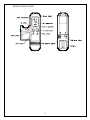
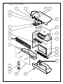
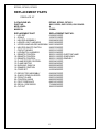
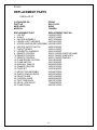
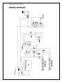
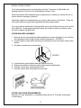
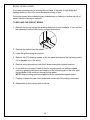
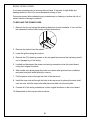
PARTS & SERVICE MANUAL
FOR THE 30” FIREPLACE
MODEL NUMBER:
EF3003
SF3003
DF3003
TABLE OF CONTENTS
OPERATION
PAGE 1
PARTS DRAWING
PAGE 5
PARTS LIST
PAGE 6
WIRING DIAGRAM
PAGE 9
LIGHT BULB REPLACEMENT
PAGE 10
LED/SWITCH HARNESS REPLACEMENT
PAGE 12
LIGHT DIMMER SWITCH REPLACEMENT
PAGE 13
FLAME SPEED CONTROL REPLACEMENT
PAGE 14
FLAME MOTOR/FLAME ROD REPLACEMENT
PAGE 15
HEATER ON/OFF SWITCH REPLACEMENT
PAGE 17
HEATER ASSEMBLY REPLACEMENT
PAGE 18
CIRCUIT BOARD REPLACEMENT
PAGE 19
POWER CORD REPLACEMENT
PAGE 20
EF3003, SF3003, DF3003
OPERATION
Initializing The Remote Control
1. Turn on the electrical power at the circuit breaker.
2. Slide open the battery cover on the back of the remote transmitter.
3. Install three AAA batteries into the remote control. Replace the battery cover.
Note:
The LCD display will flash when new batteries are inserted.
4. Move the remote transmitter close to the fireplace (less than five feet preferred).
Press any button on the remote control. The remote is transferring the code to the
receiver built into the fireplace.
5. Set the clock by depressing the button marked clock on the transmitter for five
seconds. The hour display will flash.
6. Use the up and down buttons to set the hour.
7. Press the clock button again and the minute display will flash.
8. Use the up and down buttons to set the minute.
9. Press the clock button again and the 0F or 0C display will flash.
10. Use the up and down buttons to select the remote to display temperature in 0F or 0C
11. Press the clock button again. The remote control is now ready for operation.
Remote Control Operation
Warning:
It takes some time for the receiver to respond to the transmitter. Do not press the
buttons more than once within two seconds for correct operation.
Note:
The fireplace has an automatic timer function that will shut your fireplace off if the
remote control has not been operated within a six-hour period.
Auto Mode
Note:
When auto mode is activated the flame and heat will turn on. The heater will turn on
and off to keep the room temperature the same as the remote controls set temperature.
1. Press POWER button to turn unit on. (There may be a slight delay)
2. Press the UP or DOWN buttons to change the set temperature, if desired.
3. In auto mode the remote transmitter will automatically turn on the flame and heater
when the room temperature is below the target temperature and turn off the heater
ONLY when the room temperature is above the target temperature.
4. Press POWER button once to turn unit off.
1
EF3003, SF3003, DF3003
Timer Mode
1. You can set the timer to the length of time you want the unit to operate
2. (1 to 120 minutes).
3. Press the TIMER button once. The timer display will blink --4. Press the UP and DOWN buttons to adjust the timer display in minutes.
5. Press the TIMER button once to set the timer.
6. The timer setting can be reset by pressing the TIMER button and using the DOWN
button until the timer display reads ----, press the TIMER button once to set the
timer.
7. Press the POWER button to turn the unit on.
8. The fireplace will automatically shut off when the timer reaches 0 minutes.
Child Proof Function
1. Remove the battery cover on the back of the remote control.
2. Slide the small blue switch down to activate the child proof function.
3. Child Proof will appear on the display screen and all function on the remote will be
locked.
4. To enable normal remote control operation when the child proof function is activated,
press the up and down buttons in the following sequence,
UP-DOWN-DOWN-UP-DOWN the remote functions will now operate normally. The
remote will return to the child proof function if buttons are not pressed after two
minutes.
5. To disable the child proof function remove the battery cover on the back of the
remote and slide the small blue switch up.
Batteries
1. The remote control uses 3 AAA size batteries (included). Replace these batteries at
least every 6 months or when the low battery appears on the remote display screen.
2. When batteries are removed wait at least 1 minute before replacing with new
batteries.
Code selection
If the current remote control is interfering with the operation of other remote control
devices (TV, VCR, garage doors etc.) The code can be changed on the remote.
To change code:
1. Remove the battery cover on the back of the remote control.
2. Slide the four small switches to any configuration other than the factory set code.
3. Remove the batteries, wait for one minute.
4. Install the batteries.
5. Install the battery cover onto the remote.
6. Reinitialize the remote.
2
EF3003, SF3003, DF3003
3
EF3003, SF3003, DF3003
Electric Fireplace Manual Controls
A. Manual on/off switch
1. The fireplace has a manual power ON/OFF switch located on the control panel of
the fireplace.
2. To operate press the switch once, to turn the unit on. A red light will illuminate to
indicate the power is on. Press the switch again to turn the unit off.
NOTE:
When the manual power switch is used the heater will run.
The manual ON/OFF switch is to be used only when the remote transmitter is OFF.
B. Flame brightness control
Turn the flame brightness control knob to increase or decrease the brightness of the
flame and embers.
C. Flame action control
Turn the flame action control knob to adjust the flame speed control to the desired level.
D. Heater override switch
When the Manual on/off switch is in the on position the heater will run. Turn the heater
override switch to the off position to shut off the heater.
NOTE:
Ensure that the heater override switch is in the on position for the heater to work with
the remote control.
RESETTING THE TEMPERATURE CUTOFF SWITCH
Should the heater overheat, an automatic cut out will turn the heater off and it will not
come back on without being reset. It can be reset by switching the MAIN ON/OFF
SWITCH to OFF and waiting 5 minutes before switching the unit back on.
CAUTION
If you need to continuously reset the heater, unplug the unit and call Dimplex North
America Limited at 1-800-668-6663.
4
EF3003, SF3003, DF3003
17
16
20
20
8
12
6
7
18
15
3
22
2
5
1
14
17
13
4
9
10
11
19
21
5
EF3003, SF3003, DF3003
REPLACEMENT PARTS
FIREPLACE 30”
CATALOGUE NO.
PART NO.
MOD LEVEL:
MADE IN:
EF3003, SF3003, DF3003
6901110259, 6901110359, 6901110459
A
CHINA
REPLACEMENT PART
REPLACEMENT PART NO.
1. LOG SET
0438550100RP
2. GRILLE
1009070159RP
3. HEATER ASSEMBLY
2200490201RP
4. LOWER LIGHT HARNESS
2500190500RP
5. UPPER LAMPHOLDER ASSEMBLY 4200120900RP
6. HEATER ON/OFF SWITCH
2800070200RP
7. CIRCUIT BOARD
3000210100RP
8. LED/SWITCH HARNESS
3000210400RP
9. REMOTE CONTROL
3000211600RP-ELECTRAFLAME
10. REMOTE CONTROL
3000211500RP-SYMPHONY
11. REMOTE CONTROL
3000211300RP-DIMPLEX
12. FLAME SPEED CONTROL
3000240100RP
13. FLAME MOTOR
3000240200KIT
14. BUSHING, SNAP-IN
8500000400RP
15. DIMMER CONTROL
3000250100RP
16. CORD SET
4100040500RP
17. REFLECTOR ASSEMBLY
5900080700RP
18. GLASS, SEMI-SILVERED
5900300200RP
19. FRONT GLASS
5900310200RP
20. CONTROL KNOB
8800000200RP
21. FOOT FIREPLACE
8800100100RP
22. DECAL, SIDE BRICK
7108890200RP
23. CUTOUT
2300270300RP
6
EF3003, SF3003, DF3003
REPLACEMENT PARTS
FIREPLACE 30”
CATALOGUE NO.
PART NO.
MOD LEVEL:
MADE IN:
EF3003, SF3003, DF3003
6901110259, 6901110359, 6901110459
NONE
CHINA
REPLACEMENT PART
REPLACEMENT PART NO.
1. LOG SET
0438550100RP
2. GRILLE
1009070159RP
3. HEATER ASSEMBLY
2200490200RP
4. LOWER LIGHT HARNESS
N/A
5. UPPER LAMPHOLDER ASSEMBLY 4200120900RP
6. HEATER ON/OFF SWITCH
2800070200RP
7. CIRCUIT BOARD
3000210100RP
8. LED/SWITCH HARNESS
3000210400RP
9. REMOTE CONTROL
3000211600RP-ELECTRAFLAME
10. REMOTE CONTROL
3000211500RP-SYMPHONY
11. REMOTE CONTROL
3000211300RP-DIMPLEX
12. FLAME SPEED CONTROL
3000240100RP
13. FLAME MOTOR
3000240200KIT
14. BUSHING, SNAP-IN
8500000400RP
15. DIMMER CONTROL
3000250100RP
16. CORD SET
4100040500RP
17. REFLECTOR ASSEMBLY
5900080700RP
18. GLASS, SEMI-SILVERED
5900300200RP
19. FRONT GLASS
5900310200RP
20. CONTROL KNOB
8800000200RP
21. FOOT FIREPLACE
8800100100RP
22. DECAL, SIDE BRICK
7108890200RP
7
EF3003
REPLACEMENT PARTS
FIREPLACE 30”
CATALOGUE NO.
PART NO.
MOD LEVEL:
MADE IN:
EF3003
6901110159
NONE
CANADA
REPLACEMENT PART
REPLACEMENT PART NO.
1. LOG SET
0438550100RP
2. GRILLE
1009070159RP
3. HEATER ASSEMBLY
2000170300RP
4. LOWER LIGHT HARNESS
2500190100RP
5. UPPER LAMPHOLDER ASSEMBLY 2500080100RP
6. HEATER ON/OFF SWITCH
2800070200RP
7. CIRCUIT BOARD
3000210100RP
8. LED/SWITCH HARNESS
3000210400RP
9. REMOTE CONTROL
3000211600RP-ELECTRAFLAME
10. REMOTE CONTROL
3000211500RP-SYMPHONY
11. REMOTE CONTROL
3000211300RP-DIMPLEX
12. FLAME SPEED CONTROL
3000180300RP
13. FLAME MOTOR
2000150200RP
14. BUSHING, SNAP-IN
8500000600RP
15. DIMMER CONTROL
2800020100RP
16. CORD SET
4100040400RP
17. REFLECTOR ASSEMBLY
5900080700RP
18. GLASS, SEMI-SILVERED
5900300200RP
19. FRONT GLASS
5900310200RP
20. CONTROL KNOB
8800000800RP
21. FOOT FIREPLACE
8800100100RP
22. DECAL, SIDE BRICK
7108890200RP
23. FLAME PANEL
5900320100RP
8
EF3003, SF3003, DF3003
WIRING DIAGRAM
9
EF3003, SF3003, DF3003
If unit was operating prior to servicing allow at least 10 minutes for light bulbs and
heating element to cool off to avoid accidental burning of skin.
Disconnect power before attempting any maintenance or cleaning to reduce the risk of
electric shock or damage to persons.
Light bulbs need to be replaced when you notice a dark section of the flame. There are
four bulbs under the log set which generate the flames and embers.
It is a good idea to replace all of the light bulbs at one time if they are close to the end of
their rated life. Group replacement will reduce the number of times you need to open
the unit to replace the light bulbs.
LOWER BULB REPLACEMENT
1. Remove the trim by turning the retaining fasteners counter clockwise ¼ turn until the
trim releases from the firebox using a slotted screwdriver. (FIGURE 1)
2. Hold the glass in place while removing the retaining clip from the upper center of the
firebox.
3. Lift glass out and store in a safe place.
FIGURE 1
4. Lift up the front edge of the log until it clears the front tabs. Pull out until the rear tab
clears the back ledge, then lift out.
5. Examine the bulbs to determine which bulbs require replacement.
6. Hold the socket while unscrewing the bulb.
7. Hold the socket while screwing in the new bulb.
8. Replace the log emberbed by placing the back lip of the log emberbed under the
mirror then push the front of the log emberbed down into the recess.
LOWER LIGHT BULB REQUIREMENTS
Quantity of 4 clear chandelier or candelabra bulbs with an E-12 (small) socket base,
60 watt rating.
10
EF3003, SF3003, DF3003
If unit was operating prior to servicing allow at least 10 minutes for light bulbs and
heating element to cool off to avoid accidental burning of skin.
Disconnect power before attempting any maintenance or cleaning to reduce the risk of
electric shock or damage to persons.
Light bulbs need to be replaced when you notice a dark section of the flame. There are
four bulbs under the log set which generate the flames and embers.
It is a good idea to replace all of the light bulbs at one time if they are close to the end of
their rated life. Group replacement will reduce the number of times you need to open
the unit to replace the light bulbs.
UPPER BULB REPLACEMENT
1. Remove the trim by turning the retaining fasteners counter clockwise ¼ turn until the
trim releases from the firebox using a slotted screwdriver. (FIGURE 1)
2. Hold the glass in place while removing the retaining clip from the upper center of the
firebox.
3. Lift glass out and store in a safe place.
FIGURE 1
4.
5.
6.
7.
Locate the two upper bulbs inside the firebox at the top.
Examine the bulbs to determine which bulbs require replacement.
Hold the socket while unscrewing the bulb.
Hold the socket while screwing in the new bulb.
UPPER LIGHT BULB REQUIREMENTS
Quantity of 2 clear chandelier or candelabra bulbs with an E-12 (small) socket base,
15 watt rating.
11
EF3003, SF3003, DF3003
If unit was operating prior to servicing allow at least 10 minutes for light bulbs and
heating element to cool off to avoid accidental burning of skin.
Disconnect power before attempting any maintenance or cleaning to reduce the risk of
electric shock or damage to persons.
TO REPLACE LED/SWITCH HARNESS
1. Remove the trim by turning the retaining fasteners counter clockwise ¼ turn until the
trim releases from the firebox using a slotted screwdriver.
2. Remove the firebox from mantel.
3. Lower the grill covering the controls.
4. Remove the (10) retaining screws on the top cover and remove the top being careful
not to damage any of the wiring.
5. Locate the main on/off switch mounted on the top panel and disconnect the wiring
clips and connections noting their original locations.
6. Depress the retainer clips on the rear of the switch and push the switch out of the
rear of the cover.
12
EF3003, SF3003, DF3003
If unit was operating prior to servicing allow at least 10 minutes for light bulbs and
heating element to cool off to avoid accidental burning of skin.
Disconnect power before attempting any maintenance or cleaning to reduce the risk of
electric shock or damage to persons.
TO REPLACE LIGHT DIMMER SWITCH
1. Remove the trim by turning the retaining fasteners counter clockwise ¼ turn until the
trim releases from the firebox using a slotted screwdriver.
2. Remove the firebox from the mantel.
3. Lower the grill covering the controls.
4. Remove the (10) retaining screws on the top panel and remove the top being careful
not to damage any of the wiring.
5. Pull off the control knob from the dimmer control and remove the mounting nut.
6. Locate the light dimmer control mounted on the top panel and disconnect the wiring
clips and connections noting their original locations.
7. From under the top panel, break off the four mounting studs on the light dimmer
control by grasping with pliers and twisting on the protruding part of the stud, push
the remainder of the studs out through the top panel.
NOTE: New mounting studs are supplied with the replacement light dimmer.
8. Properly orientate the new light dimmer control and connect all of the wiring
connections.
9. Reassemble in the reverse order as above.
13
EF3003, SF3003, DF3003
If unit was operating prior to servicing allow at least 10 minutes for light bulbs and
heating element to cool off to avoid accidental burning of skin.
Disconnect power before attempting any maintenance or cleaning to reduce the risk of
electric shock or damage to persons.
TO REPLACE FLAME SPEED CONTROL
1. Remove the trim by turning the retaining fasteners counter clockwise ¼ turn until the
trim releases from the firebox using a slotted screwdriver.
2. Remove the firebox from the mantel.
3. Lower the grill covering the controls.
4. Remove the (10) retaining screws on the top panel and remove the top being careful
not to damage any of the wiring.
5. Pull off the control knob from the flame speed control and remove the mounting nut.
6. Locate the flame speed control mounted on the top panel and disconnect the wiring
clips and connections noting their original locations.
7. From under the top panel, break off the four mounting studs on the flame speed
control by grasping with pliers and twisting on the protruding part of the stud, push
the remainder of the studs out through the top panel.
NOTE: New mounting studs are supplied with the replacement speed control.
8. Properly orientate the new flame speed control and connect all of the wiring
connections.
9. Reassemble in the reverse order as above.
14
EF3003, SF3003, DF3003
If unit was operating prior to servicing allow at least 10 minutes for light bulbs and
heating element to cool off to avoid accidental burning of skin.
Disconnect power before attempting any maintenance or cleaning to reduce the risk of
electric shock or damage to persons.
TO REPLACE FLAME MOTOR/FLAME ROD
1. Remove the trim by turning the retaining fasteners counter clockwise ¼ turn until the
trim releases from the firebox using a slotted screwdriver.
2. Remove the firebox from the mantel.
3. Remove front glass retaining clip, while holding the front glass.
4. Remove the front glass and set aside.
5. Remove the log set by lifting up the front edge of the log until it clears the front tabs.
Pull out until the rear tab clears the back ledge, then lift out.
6. Cut the flicker motor wires close to the flicker motor end with wire cutters.
7. Remove the reflector rod from the flicker motor by pulling the end of the rod to the
left and cut the reflector spring with wire cutters. DO NOT TAKE THE LEFTOVER
SPRING OFF THE END OF THE REFLECTOR ROD
8. Remove the (2) screws securing the flicker motor to the flicker motor bracket.
9. Discard the old flicker motor.
10. Pick up the 1 ½” rubber sleeve and locate over remaining spring on reflector rod.
ENSURE TO LOCATE THE LARGE OPENING OF THE RUBBER SLEEVE OVER
THE REMAINING SPRING OF THE REFLECTOR ROD.
11. Pick up new flicker motor and cut wire leads to 3 ½” long with wire cutters.
12. Secure new flicker motor to the existing reflector rod. Ensure the flicker motor
bracket is in between the motor and the reflector rod.
13. Pick up slip joint pliers and adjust to proper slot.
15
EF3003, SF3003, DF3003
If unit was operating prior to servicing allow at least 10 minutes for light bulbs and
heating element to cool off to avoid accidental burning of skin.
Disconnect power before attempting any maintenance or cleaning to reduce the risk of
electric shock or damage to persons.
TO REPLACE FLAME MOTOR/FLAME ROD
14. Pick up wire connector and place (1) yellow wire into each terminal. (total of 2
yellow wires)
15. Secure wire connector by crimping the 3M symbol with slip joint pliers.
16. Pull on end of wires to ensure a strong connection.
17. Repeat this process for the (4) remaining wires. (red, blue, orange, grey)
18. Reassemble in the reverse order.
16
EF3003, SF3003, DF3003
If unit was operating prior to servicing allow at least 10 minutes for light bulbs and
heating element to cool off to avoid accidental burning of skin.
Disconnect power before attempting any maintenance or cleaning to reduce the risk of
electric shock or damage to persons.
TO REPLACE HEATER ON/OFF SWITCH
1. Remove the trim by turning the retaining fasteners counter clockwise ¼ turn until the
trim releases from the firebox using a slotted screwdriver.
2. Remove the firebox from the mantel.
3. Lower the grill covering the controls.
4. Remove the (10) retaining screws on the top panel and remove the top being careful
not to damage any of the wiring.
5. Locate the heater on/off switch mounted to the top panel and disconnect the wiring
clips and connections noting their original locations.
6. Depress the retainer clips on the rear of the switch and push the switch out of the
rear cover.
7. Properly orientate the new switch and connect all of the wiring clips and
connections.
8. Reassemble in the reverse order as above
17
EF3003, SF3003, DF3003
If unit was operating prior to servicing allow at least 10 minutes for light bulbs and
heating element to cool off to avoid accidental burning of skin.
Disconnect power before attempting any maintenance or cleaning to reduce the risk of
electric shock or damage to persons.
TO REPLACE HEATER ASSEMBLY
1. Remove the trim by turning the retaining fasteners counter clockwise ¼ turn until the
trim releases from the firebox using a slotted screwdriver.
2. Remove the firebox from the mantel.
3. Lower the grill covering the controls.
4. Remove the (10) retaining screws on the top panel and remove the top being careful not
to damage any of the wiring.
5. Hold the glass in place while removing the retaining clip from the upper center of the
firebox.
6. Lift glass out and store in a safe place.
7. Locate the two upper bulbs inside the firebox at the top.
8. Hold the light sockets while unscrewing the bulbs.
9. Remove the yellow wire from the heater element coming from the heater on/off switch.
10. Remove the blue wire from the circuit board coming from the temperature cutoff switch.
11. Remove the (2) element mounting screws from the top of the element located on both
sides of the temperature cutoff switch.
12. Remove the (4) heater assembly mounting screws from inside the firebox and set aside
the heater assembly.
13. Disconnect wiring connections and connect to replacement heater assembly noting their
original locations.
14. Reassemble in the reverse order as above.
18
EF3003, SF3003, DF3003
If unit was operating prior to servicing allow at least 10 minutes for light bulbs and
heating element to cool off to avoid accidental burning of skin.
Disconnect power before attempting any maintenance or cleaning to reduce the risk of
electric shock or damage to persons.
TO REPLACE THE CIRCUIT BOARD
1. Remove the trim by turning the retaining fasteners counter clockwise ¼ turn until the
trim releases from the firebox using a slotted screwdriver.
2. Remove the firebox from the mantel.
3. Lower the grill covering the controls.
4. Remove the (10) retaining screws on the top panel and remove the top being careful
not to damage any of the wiring.
5. Remove wiring connections from circuit board noting their original locations.
6. From under the top panel, break off the six mounting studs on the flame speed
control by grasping with pliers and twisting on the protruding part of the stud, push
the remainder of the studs out through the top panel.
NOTE: New mounting studs are supplied with the replacement speed control.
7. Properly orientate the new circuit board and connect all of the wiring connections.
8. Reassemble in the reverse order as above.
19
EF3003, SF3003, DF3003
If unit was operating prior to servicing allow at least 10 minutes for light bulbs and
heating element to cool off to avoid accidental burning of skin.
Disconnect power before attempting any maintenance or cleaning to reduce the risk of
electric shock or damage to persons.
TO REPLACE THE POWER CORD
1. Remove the trim by turning the retaining fasteners counter clockwise ¼ turn until the
trim releases from the firebox using a slotted screwdriver.
2. Remove the firebox from the mantel.
3. Lower the grill covering the controls.
4. Remove the (10) retaining screws on the top panel and remove the top being careful
not to damage any of the wiring.
5. Located and disconnect the power cord wiring connections from the circuit board
noting their original locations.
6. With needle nose pliers grasp the power cord strain relief grommet from inside the
rear panel and push while twisting to remove.
7. Pull the power cord out through the hole in the rear cover.
8. Install the new cord set through the hole in the rear cover by placing the strain relief
over the cord, hold the strain relief with pliers and slide into mounting hole.
9. Connect all of the wiring connections in their original locations on the circuit board.
10. Reassemble in the reverse order as above.
20