1
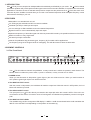
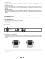
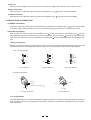
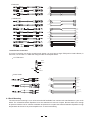
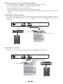
User's Manual
ALTO Q
5-BAND PARAMETRIC EQUALIZER
R
LTO
www.altoproaudio.com
Version 2.1 Dec. 2002
English
the recommended fuse type as indicated in this manual.
Do not short-circuit the fuse holder. Before replacing the
fuse, make sure that the product is OFF and disconnected
from the AC outlet.
SAFETY RELATED SYMBOLS
CAUTION
RISK OF ELECTRIC SHOCK
DO NOT OPEN
Protective Ground
This symbol, wherever used, alerts you to the presence of un-insulated and dangerous voltages within the product enclosure. These are voltages that
may be sufficient to constitute the risk of electric
shock or death.
Before turning the product ON, make sure that it is
connected to Ground. This is to prevent the risk of
electric shock.
Never cut internal or external Ground wires. Likewise,
never remove Ground wiring from the Protective Ground
Terminal.
This symbol, wherever used, alerts you to important operating and maintenance instructions.
Please read.
Operating Conditions
Always install in accordance with the manufacturer's
instructions.
Protective Ground Terminal
To avoid the risk of electric shock and damage, do not
subject this product to any liquid/rain or moisture. Do
not use this product when in close proximity to water.
AC mains (Alternating Current)
Hazardous Live Terminal
ON:
Denotes the product is turned on.
Do not install this product near any direct heat source.
OFF: Denotes the product is turned off.
Do not block areas of ventilation. Failure to do so could
result in fire.
Keep product away from naked flames.
WARNING
Describes precautions that should be observed to
prevent the possibility of death or injury to the user.
IMPORTANT SAFETY INSTRUCTIONS
CAUTION
Read these instructions
Describes precautions that should be observed to
prevent damage to the product.
Follow all instructions
Keep these instructions. Do not discard.
Heed all warnings.
WARNING
Only use attachments/accessories specified by the
manufacturer.
Power Supply
Ensure that the mains source voltage (AC outlet) matches
the voltage rating of the product. Failure to do so could
Power Cord and Plug
result in damage to the product and possibly the user.
Unplug the product before electrical storms occur and
when unused for long periods of time to reduce the risk of
Do not tamper with the power cord or plug. These are
designed for your safety.
electric shock or fire.
If the plug does not fit your AC outlet seek advice from a
qualified electrician.
Do not remove Ground connections!
External Connection
Always use proper ready-made insulated mains
cabling (power cord). Failure to do so could result
in shock/death or fire. If in doubt, seek advice from
Protect the power cord and plug from any physical
stress to avoid risk of electric shock.
Do not place heavy objects on the power cord. This
could cause electric shock or fire.
a registered electrician.
Cleaning
Do Not Remove Any Covers
Within the product are areas where high voltages may
present. To reduce the risk of electric shock do not remove
any covers unless the AC mains power cord is removed.
When required, either blow off dust from the product or
use a dry cloth.
Do not use any solvents such as Benzol or Alcohol.
For safety, keep product clean and free from dust.
Covers should be removed by qualified service
personnel only.
Servicing
No user serviceable parts inside.
Refer all servicing to qualified service personnel only. Do
not perform any servicing other than those instructions
contained within the User's Manual.
Fuse
To prevent fire and damage to the product, use only
1
PREFACE
Dear Customer:
Thanks for choosing LTO-Q 5-Band Parametric Equalizer and thanks for choosing one of the results of
AUDIO TEAM job and researches.
LTO
For our LTO AUDIO TEAM, music and sound are more than a job...are first of all passion and let us say...our
obsession!
We have been designing professional audio products for a long time in cooperation with some of the major brands
in the world in the audio field.
The LTO line presents unparalleled analogue and digital products made by Musicians for Musicians in our R&D
Centres in Italy, Netherlands, United Kingdom and Taiwan. The core of our digital audio products is a sophisticated
DSP (Digital sound processor) and a large range of state of the art algorithms which have been developed by our
Software Team for the last 7 years.
Because we are convinced you are the most important member of LTO AUDIO TEAM and the one confirming
the quality of our job, we would like to share with you our work and our dreams, pay attention to your suggestions
and your comments.
Following this idea we create our products and we will create the new ones! From our side, we guarantee you
and we will guarantee you also in future the best quality, and the best fruits of our continuous researches and the
best prices.
Our LTO 5-Band Parametric Equalizer is the result of many hours of listening and tests involving common
people, area experts, musicians and technicians.
The results of this effort is a high-end 5-Band Parametric Equalizer which will provide a permanent precise equalization to the musician, performer, studio engineer and sound contractor.
Nothing else to add, but that we would like to thank all the people that made the LTO 5-Band Parametric
Equalizer a reality available to our customers, thank our designers and all LTO staff, there to make possible the
realization of products containing our idea of music and sound and there to support you, our customers, in the
best way, conscious that you are our best richness.
Thank you very much.
LTO AUDIO TEAM
2
TABLE OF CONTENT
1. INTRODUCTION ....................................................................................................................................4
2. FEATURES ............................................................................................................................................4
3. ELEMENT CONTROLS..........................................................................................................................4
3.1 The Front Panel
3.2 The Rear Panel
4. INSTALLATION & CONNECTION .........................................................................................................6
4.1 Mains Connection
4.2 Audio Connection
- Wiring Configuration
- In Line Connection
- Insert Points Connection
4.3 Rack Mounting
5. APPLICATION...........................................................................................................................................8
5.1 The Frequency Range of music Instruments
5.2 Using your
LTO-Q in a sound reinforcement system
5.3 Application on single instrument
5.4 Application on main MIX
6. TECHNICAL SPECIFICATIONS ...........................................................................................................10
7. WARRANTY ..........................................................................................................................................11
3
1. INTRODUCTION
With LTO-Q you have acquired an indispensable toll to add clarity and flexibility to your music. The LTO-Q 5 bands
parametric equaliser will provide precise audio signal control to fixed sound installation, live performance and studio
applications. Thanks to the use of selected and expensive components the performances of LTO-Q are worth much
more than its price: Variable Q controls allow you to notch out unwanted frequencies while sweepable frequency control
add maximum flexibility to your mix.
2.FEATURES
Mountable in one standard rack unit 19"
1/4" TRS type jack and balanced XLR connectors available
Led Meter (12 LED) to read input and output
Low cut and high cut filters available to cancel unwanted frequencies
Bypass function to connect automatically input and output
Optimum transparency of the audio signal and minimum phase shift insured by the parallel architecture of the filters
Switch-on button on every single band
Constant Q principle combination
5 bands of equalisation fully parametric (gain, frequency, Q) for studio and live applications
The frequency range of the single 5 bands is overlapping. This will allow extreme boost or attenuation
3.ELEMENT CONTROLS
3.1 The Front Panel
11
4
2
INPUT / OUTPUT LEVEL (dB)
BAND 1
IN
20Hz - 400Hz
IN / OUT
BAND 2
OUT
IN
60Hz - 1KHz
IN / OUT
BAND 3
OUT
IN
150Hz - 2.5KHz
IN / OUT
BAND 4
OUT
IN
500Hz - 8KHz
IN / OUT
BAND 5
OUT
IN
1KHz - 20KHz
IN / OUT
-30
OUT
-24
-18
-12
-6
-3
0
+3
+6
+9
I / O METER
+12 +18
OUTPUT
1.2
110
R
LTO
45
150
30
-5
20
400
+5
0.03
1.6
Hz
OCTAVE
FREQUENCY
BANDWIDTH
120
-15
+15
dB
LEVEL
-5
60
1K
+5
-10
600
0.03
1.6
Hz
OCTAVE
FREQUENCY
BANDWIDTH
1.2
720
0
360
+10 70
-10
250
1.2
260
0
1K
350
+10 200
-15
+15
dB
LEVEL
-5
2.5K
+5
-10
1.6K
150
2.3
0
0.03
1.6
Hz
OCTAVE
FREQUENCY
BANDWIDTH
1.0
1.2
+15
dB
LEVEL
0.5
8.0
KHz
FREQUENCY
+5
-10
4.8
0.03
1.6
OCTAVE
BANDWIDTH
1.2
5.1
-5
3.1
+10 0.6
-15
0
2.2
7.0
+10 1.3
-15
+15
dB
LEVEL
-5
20
+5
0.03
1.6
50
110
-15
+15
200
3.5
10
400
22
2.5
30
-10
5-BAND PARAMETRIC
EQUALIZER
OFF
-15
+15
KHz
OCTAVE
Hz
KHz
dB
BANDWIDTH
LEVEL
LOW CUT
HIGH CUT
INPUT
10
9
8
7
6
ON
+10 AUDIO
FREQUENCY
dB
Q
+5
-5
15
7
INPUT
0
10
+10 25
-10
12
1.0
75
0
5
OUT
IN
POWER
3
1
Your LTO-Q includes 5 channels of equalisation. 3 rotary controls and 1 switch are present in each channel. The
Master Section includes the power switch, 2 push-on switches, 3 rotary controls and 12 LED's.
1.POWER switch
When you set this switch in ON position (green light on) the unit will be turned on. When you set this switch in
OFF position (green light off) the unit will be turned off.
2.The INPUT/OUTPUT control
With this control in ON position, the Led Meter will read the output level. With this control in OFF position, the Led
Meter will read the input level.
3.The AUDIO IN/OUT control
The input jack of your LTO-Q is directly connected to the output jack when this control is OFF or if the unit is not
connected to the AC socket. It is used to cause a "hard-bypass" and disable the equalisation process in the signal
path.
4.The INPUT/OUTPUT LEVEL
The readable range of this 12 segments LED display is -30dB to +18dB. As mentioned before it will read either the
INPUT or the OUTPUT level depending on the position of the switch (2).
4
5.The INPUT control
You can control the amount of the audio signal fed into your
to +15dB.
LTO-Q via this control. The range goes from -15dB
6.The HIGH CUT control
This control, when activated will cut the high frequencies with a slope of 12dB per octave in a range of 2.5 kHz to
30 kHz. So if you set this control at the maximum position of 30 kHz, the audio signal will pass through without
alteration.
7.The LOW CUT control
This control, when activated will cut the low frequencies with a slope of 12dB per octave in a range of 10 Hz to
400 Hz. So if you set this control at the minimum position of 10 Hz, the audio signal will pass through without
alteration.
8.The LEVEL control
The level boost or attenuation is set with this control. The adjusting range goes from -15dB to +15dB.
9.The BANDWIDHT control
This control adjusts the width and can be set from a minimum of 0.03 octaves to a maximum of 1.6 octaves.
10.The FREQUENCY control
This control set the center frequency point of the filter.
11.IN/OUT switch
It activates/disactivates the correspondent band.
3.2 The Rear Panel
12
AC INPUT
110-120V
95-120V /210-240V 60-50Hz
Rated Power Consumption 9W
220-240V
TIP / PIN 2
RING / PIN3
SLEEVE / PIN 1
TIP / PIN 2
RING / PIN3
SLEEVE / PIN 1
FUSE:
210-240V: T200mAL 250VAC
95-120V: T315mA 250VAC
REPLACE FUSE WITH CORRECT TYPE ONLY
NEW
TIDE
NEW
3
2
TIDE
3
1
2
1
Apparaten skall anslutas till
jordat uttag nar den ansluts
till ett natverk
A101
INPUT
OUTPUT
13
14
15
12.Voltage Selector and Fuse Holder
You must be sure of the Voltage available in your Country because this is a Dual Voltage Unit. Voltage operation
can be changed through the fuse protecting the power supply but this operation must be performed by a qualified
Engineer.
220-240V
110-120V
220-240V
110-120V
THIS IS SET FOR
110V AC TO 120V
AC OPERATION
THIS IS SET FOR
220V AC TO 240V
AC OPERATION
Please note the triangular markers on both sides of the fuse holder (See figure above), To change the voltage pull
the fuse holder out, rotate it 180 and push it back again. The operating voltage will be indicated by one of the two
triangular markers.
5
13.AC Inlet
After the correct voltage has been set you can connect the AC plug to the unit and in the AC power socket.
14.Input Connectors
Both XLR and 1/4" TRS jack input connectors are supplied in your
LTO-Q for maximum flexibility.
15.Output Connector
Both XLR and 1/4" TRS jack output connectors are supplied in your
LTO-Q for maximum flexibility.
4. INSTALLATION & CONNECTION
4.1 Mains Connection
A Main AC cable that meets all the international safety regulations is supplied with your LTO-Q. Please make
sure of the supply voltage available in your Country before plugging in the power cord into the AC socket.
4.2 Audio Connection
Both XLR and 1/4" TRS connectors are available on your LTO-Q. In this way you can interface your LTO-Q in
several different ways without experiencing any noise or signal loss. You can use your LTO-Q with single instruments
using the mixers main insert or on the complete mix connecting the LTO-Q in between the mixer and the power amplifier.
- Wiring Configuration
Either the 1/4" TRS phone jack or the XLR connector can be wired in balanced and unbalanced modes, which will
be determined by the actual application status, please wire your system as the following wiring examples:
For 1/4" Phone jack
+
+
-
Tip
Ring
+
Tip
Tip
Ring
Sleeve
Sleeve
TS Type Unbalanced
Sleeve
TRS Type Balanced
TRS Type Unbalanced
For XLR connector
Pin2 (+)
Pin3 (-)
(Linked to Pin1 manually,
Pin2 (+)
Pin3 (-)
)
Pin1 ( )
Pin1 ( )
XLR Type Unbalanced
XLR Type Balanced
- In Line Connection
For these applications the 5-Band Parametric Equalizer provides 1/4" TRS connectors and XLR connectors to
easily interface with most any professional audio device. Follow the configuration examples below for your particular connection.
6
Balanced
Tip
Ring
Sleeve
SLEEVE RING TIP
TIP RING SLEEVE
3
3
1
1
2
2
1
3
2
TIP RING SLEEVE
Tip
Ring
Sleeve
1
2
1
2
3
3
Tip
Ring
1
2
3
Sleeve
Unbalanced
1
Tip
Ring
3
2
Sleeve
TIP RING SLEEVE
Tip
1
3
2
Sleeve
1
2
3
1
2
3
1
TIP SLEEVE
2
3
1
2
3
Tip
TIP SLEEVE
Sleeve
SLEEVE TIP
Tip
Ring
TIP RING SLEEVE
SLEEVE RING TIP
Cent r e
Screen
Tip
Sleeve
Tip
Ring
Sleeve
Sleeve
Tip
Cent r e
Sleeve
Screen
Tip
Ring
Centre
Sleeve
Screen
TIP SLEEVE
TIP RING SLEEVE
3
3
1
1
1
2
2
2
3
1
2
3
- Insert Points Connection
If you are connecting to a mixing console's main inserts, you may have a single TRS jack for Send & Return, in
this case, use an insert "Y" cable that configured like the examples below.
1/4" TRS insert
Send
Return
Tip
Ring
Sleeve
Insert Leads
Tip
Ring
Sleeve
SLEEVE TIP
TIP RING SLEEVE
Tip (Send)
Sleeve
Tip (Return)
Sleeve
SLEEVE RING TIP
1
2 (Send)
1
3
Tip
Ring
Sleeve
2
2
3
1
TIP RING SLEEVE
3
1
2 (Return)
3
Tip
Ring
Sleeve
TIP RING SLEEVE
Centre (Send)
Screen
Centre (Return)
Screen
4.3 Rack Mounting
The most secure mounting is on a universal rack shelf available from various rack manufactures or your music
dealer. The 5-Band Parametric Equalizer fit into one standard 19" rack unit of space. Be sure that there is enough
air space around the unit for sufficient ventilation and please do not place the 5-Band Parametric Equalizer on high
temperature devices such as power amplifiers etc. to avoid overheating.
7
5. APPLICATION
5.1 The Frequency Range of music Instruments
Please look at the following table. It gives you an idea of the frequency coverage of the main musical instruments and the human voice. Select a specific instrument and start to "play" with your LTO-Q applying the
five bands available on the covered frequencies. Adjust GAIN first and then FREQUENCY and finally Q.
See how much control your
LTO-Q will give you allowing a perfect contour of your sound.
Mid C
CDEFGABCDEFGABCDEFGABCDEFGABCDEFGABCDEFGABCDEFGABCDEFGABCDEFGABC
25
31
40
50
62
80 100 125 160 200 250 320 400 500 640 800 1K 1.3K 1.6K 2K 2.5K 3.1K 4K
5K 6.2K 8K 10K 13K 16K 20K
Human hearing range
VOCAL
Soprano
Contralto
Baritone
Bass
WOODWIND
Piccolo
Flute
Oboe
Clarinet in B flat or A
Clarinet in E flat
Bass Clarinet
Basset Hom
Cor Anglais
Bassoon
Double Bassoon
BRASS
Soprano Saxophone
Alto Saxophone
Tenor Saxophone
Baritone Saxophone
Bass Saxophone
Trumpet in C
Trumpet in F
Alto Trombone
Tenor Trombone
Bass Trombone
Tuba
Valve Hom
STRINGS
Violin
Viola
Cello
Double Bass
Guitar
KEYBOARDS
Pianoforte
Organ
PERCUSSION
Celesta
Timpani
Xylophone
25
31
40
50
62
80 100 125 160 200 250 320 400 500 640 800 1K 1.3K1.6K 2K 2.5K 3.1K 4K
8
5K 6.2K 8K 10K 13K 16K 20K
FREQUENCY
5.2 Using your
LTO-Q in a sound reinforcement system
You can successfully use your
LTO-Q in a sound reinforcement system in order to:
Cut out undesirable frequencies such as tape hiss and/or floor rumble.
Create sounds effects enlarging the stereo image.
Eliminate feedback using very sharp Q control on selected frequencies.
Overboost or overattenuate selected frequencies thanks to the overlapping frequency range of the five bands
available.
5.3 Application on single instrument
If you wish to use your LTO-Q as an "in line" processor and use it for single instrument equalisation, you must
connect the output of the instrument to the input of your LTO-Q and the output of the LTO-Q to the input of
an amplifier.
AC INPUT
TIP / PIN 2
RING / PIN3
SLEEVE / PIN 1
110-120V
95-120V /210-240V 60-50Hz
Rated Power Consumption 9W
220-240V
TIP / PIN 2
RING / PIN3
SLEEVE / PIN 1
FUSE:
210-240V: T200mAL 250VAC
95-120V: T315mA 250VAC
REPLACE FUSE WITH CORRECT TYPE ONLY
NEW
TIDE
NEW
3
2
TIDE
3
1
2
1
Apparaten skall anslutas till
jordat uttag nar den ansluts
till ett natverk
A101
INPUT
OUTPUT
Input
Main Output
MIC level signal
Stereo Program Source
5.4 Application on main MIX
Follow this chart and you will use the total flexibility of your
AC INPUT
110-120V
95-120V /210-240V 60-50Hz
Rated Power Consumption 9W
220-240V
TIP / PIN 2
RING / PIN3
SLEEVE / PIN 1
TIP / PIN 2
RING / PIN3
SLEEVE / PIN 1
FUSE:
210-240V: T200mAL 250VAC
95-120V: T315mA 250VAC
REPLACE FUSE WITH CORRECT TYPE ONLY
A101
LTO-Q on the Main Mix.
NEW
TIDE
NEW
3
2
TIDE
3
1
2
1
Apparaten skall anslutas till
jordat uttag nar den ansluts
till ett natverk
INPUT
OUTPUT
Main Output
Insert
MIC level signal
9
6. TECHNICAL SPECIFICATIONS
AUDIO INPUT
Type
Active balanced XLR and 1/4" JACK
Impedance
Balanced: 50kOhm Unbalanced: 25kOhm
Operating level
+4dBu/
10dBV
Maximum input level
Balanced and Unbalanced: +18dBV
CMRR
>55dB @1kHz
Type
XLR and 1/4" JACK
Impedance
Balanced: 60Ohm Unbalanced: 30Ohm
Maximum output level
+18dBV
Bandwidth
THD+N%
18Hz to 30kHz at 3dBV
0.02% typ. 1kHz, @+4dBu
IMD
0.04% typ. 1kHz, @
0.01% typ
AUDIO OUTPUT
SYSTEM SPECIFICATIONS
Noise
Frequency response
10dBu
>-92dBr unweighted 22Hz to 22kHz
Low cut
18Hz to 28kHz, 3dB
Variable (10Hz to 400Hz)
High cut
Variable (2.5kHz to 30kHz)
Level
Variable (
Frequency
Band1: 20Hz to 400Hz
PARAMETRIC FILTER
15dB)
Band2: 60Hz to 1kHz
Band3: 150Hz to 2.5kHz
Band4: 500Hz to 8kHz
Bandwidth
Band5: 1kHz to 20kHz
Variable (0.03 to 1.6 octaves)
Audio IN/OUT
Relay controlled hard
I/O meter IN/OUT
Switches the meter display from input to output
IN/OUT
Activates each filter band
Input/output level
12-segment LED display:
FUNCTION SWITCHES
bypass
INDICATORS
-30/-24/-18/-12/-6/-3/0/+3/+6/+9/+12/+18dB
Function switch
LED indicator of every switch
Main voltages
AC: 210
POWER SUPPLY
AC: 95
Power consumption
9watts
Fuse
210
95
240VAC~50Hz
120VAC~60Hz
240V: T200mAL 250VAC
120V: T315mA 250VAC
PHYSICAL
Dimension
483(W)
Weight
3.23kg
10
194.1(D)
44(H)mm
7. WARRANTY
1. WARRANTY REGISTRATION CARD
To obtain Warranty Service, the buyer should first fill out and return the enclosed Warranty Registration Card within
10 days of the Purchase Date.
All the information presented in this Warranty Registration Card gives the manufacturer a better understanding of
the sales status, so as to purport a more effective and efficient after-sales warranty service.
Please fill out all the information carefully and genuinely, miswriting or absence of this card will void your warranty
service.
2. RETURN NOTICE
2.1 In case of return for any warranty service, please make sure that the product is well packed in its original shipping
carton, and it can protect your unit from any other extra damage.
2.2 Please provide a copy of your sales receipt or other proof of purchase with the returned machine, and give detail
information about your return address and contact telephone number.
2.3 A brief description of the defect will be appreciated.
2.4 Please prepay all the costs involved in the return shipping, handling and insurance.
3. TERMS AND CONDITIONS
3.1
LTO warrants that this product will be free from any defects in materials and/or workmanship for a period
of 1 year from the purchase date if you have completed the Warranty Registration Card in time.
3.2 The warranty service is only available to the original consumer, who purchased this product directly from the
retail dealer, and it can not be transferred.
3.3 During the warranty service, LTO may repair or replace this product at its own option at no charge to you for
parts or for labor in accordance with the right side of this limited warranty.
3.4 This warranty does not apply to the damages to this product that occurred as the following conditions:
Instead of operating in accordance with the user's manual thoroughly, any abuse or misuse of this product.
Normal tear and wear.
The product has been altered or modified in any way.
Damage which may have been caused either directly or indirectly by another product / force / etc.
Abnormal service or repairing by anyone other than the qualified personnel or technician.
And in such cases, all the expenses will be charged to the buyer.
3.5 In no event shall LTO be liable for any incidental or consequential damages. Some states do not allow the exclusion or limitation of incidental or consequential damages, so the above exclusion or limitation may not apply to you.
3.6 This warranty gives you the specific rights, and these rights are compatible with the state laws, you may also
have other statutory rights that may vary from state to state.
11
SEIKAKU TECHNICAL GROUP LIMITED
No. 1, Lane 17, Sec. 2, Han Shi W. Road, Taichung, 401 Taiwan
http://www.altomobile.com Tel: 886-4-22313737
email: [email protected] Fax: 886-4-22346757
All rights reserved to ALTO Mobile. Due to continued development in response to
customer feedback, product features, specifications and/or internal/external design may be
changed without prior notice. No photocopying, translation or reproduction of any part of this user
manual is allowed without prior written permission.Copyright c 2004 Seikaku Technical Group Limited.
NF00961-1.0