1
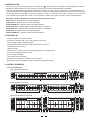
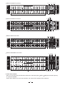
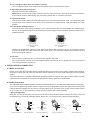
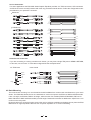
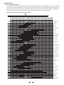
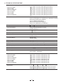
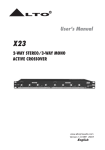
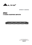
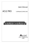
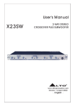
User's Manual
EQU MK
15/31 Band
Graphic Equalizer
Series
31 Band Graphic Equalizer
OUTPUT
+12 +6
+12
LTO
R
EQU131VU
POWER OUTPUT
R
0
LTO
0dB
INPUT
SIG
6
-12 - 6
20
25
31.5
40
50
63
80
100
125
160
200
250
315
400
500
630
800
1K
1.25K
1.6K
2K
2.5K
3.15K
4K
5K
6.3K
8K
10K
12.5K
16K
20K
12
OUTPUT
CLIP
SIG
40Hz
16KHz
ON
HI
PASS
LOW
PASS
EQ
GRAPHIC MONO
31 BAND EQUALIZER
/VU METER
CLIP
-12
INPUT
LEVEL
RANGE
R
LTO
www.altoproaudio.com
Version 1.3 April 2005
English
the recommended fuse type as indicated in this manual.
Do not short-circuit the fuse holder. Before replacing the
fuse, make sure that the product is OFF and disconnected
from the AC outlet.
SAFETY RELATED SYMBOLS
CAUTION
RISK OF ELECTRIC SHOCK
DO NOT OPEN
Protective Ground
This symbol, wherever used, alerts you to the presence of un-insulated and dangerous voltages within the product enclosure. These are voltages that
may be sufficient to constitute the risk of electric
shock or death.
Before turning the product ON, make sure that it is
connected to Ground. This is to prevent the risk of
electric shock.
Never cut internal or external Ground wires. Likewise,
never remove Ground wiring from the Protective Ground
Terminal.
This symbol, wherever used, alerts you to important operating and maintenance instructions.
Please read.
Operating Conditions
Always install in accordance with the manufacturer's
instructions.
Protective Ground Terminal
To avoid the risk of electric shock and damage, do not
subject this product to any liquid/rain or moisture. Do
not use this product when in close proximity to water.
AC mains (Alternating Current)
Hazardous Live Terminal
ON:
Denotes the product is turned on.
Do not install this product near any direct heat source.
OFF: Denotes the product is turned off.
Do not block areas of ventilation. Failure to do so could
result in fire.
Keep product away from naked flames.
WARNING
Describes precautions that should be observed to
prevent the possibility of death or injury to the user.
IMPORTANT SAFETY INSTRUCTIONS
CAUTION
Read these instructions
Describes precautions that should be observed to
prevent damage to the product.
Follow all instructions
Keep these instructions. Do not discard.
Heed all warnings.
WARNING
Only use attachments/accessories specified by the
manufacturer.
Power Supply
Ensure that the mains source voltage (AC outlet) matches
the voltage rating of the product. Failure to do so could
Power Cord and Plug
result in damage to the product and possibly the user.
Unplug the product before electrical storms occur and
when unused for long periods of time to reduce the risk of
Do not tamper with the power cord or plug. These are
designed for your safety.
electric shock or fire.
If the plug does not fit your AC outlet seek advice from a
qualified electrician.
Do not remove Ground connections!
External Connection
Always use proper ready-made insulated mains
cabling (power cord). Failure to do so could result
in shock/death or fire. If in doubt, seek advice from
Protect the power cord and plug from any physical
stress to avoid risk of electric shock.
Do not place heavy objects on the power cord. This
could cause electric shock or fire.
a registered electrician.
Cleaning
Do Not Remove Any Covers
Within the product are areas where high voltages may
present. To reduce the risk of electric shock do not remove
any covers unless the AC mains power cord is removed.
When required, either blow off dust from the product or
use a dry cloth.
Do not use any solvents such as Benzol or Alcohol.
For safety, keep product clean and free from dust.
Covers should be removed by qualified service
personnel only.
Servicing
No user serviceable parts inside.
Refer all servicing to qualified service personnel only. Do
not perform any servicing other than those instructions
contained within the User's Manual.
Fuse
To prevent fire and damage to the product, use only
1
Preface
Dear Customer:
Thanks for choosing
and researches.
LTO Graphic Equalizer and thanks for choosing one of the results of
LTO AUDIO TEAM job
For our LTO AUDIO TEAM, music and sound are more than a job...are first of all passion and let us say...our obse
-ssion!
We have been designing professional audio products for a long time in cooperation with some of the major brands in
the world in the audio field.
The LTO line presents unparalleled analogue and digital products made by Musicians for Musicians in our R&D
Centres in Italy, Netherlands, United Kingdom and Taiwan. The core of our digital audio products is a sophisticated
DSP (Digital sound processor) and a large range of state of the art algorithms which have been developed by our
Software Team for the last 7 years.
Because we are convinced you are the most important member of LTO AUDIO TEAM and the one confirming the
quality of our job, we would like to share with you our work and our dreams, pay attention to your suggestions and
your comments.
Following this idea we create our products and we will create the new ones! From our side, we guarantee you and we
will guarantee you also in future the best quality, and the best fruits of our continuous researches and the best prices.
Our LTO Graphic Equalizer is the result of many hours of listening and tests involving common people, area experts,
musicians and technicians.
The results of this effort is a high-end Graphic Equalizer which will provide a permanent precise equalization to the
musician, performer, studio engineer and sound contractor.
Nothing else to add, but that we would like to thank all the people that made the LTO Graphic Equalizer a reality
available to our customers, thank our designers and all LTO staff, there to make possible the realization of products
containing our idea of music and sound and there to support you, our customers, in the best way, conscious that you
are our best richness.
Thank you very much.
LTO AUDIO TEAM
2
TABLE OF CONTENT
1. INTRODUCTION ...................................................................................................................................4
2. FEATURE LIST .....................................................................................................................................4
3. CONTROL ELEMENTS.........................................................................................................................4
3.1 The Front Panel
3.2 The Rear Panel
4. INSTALLATION & CONNECTION .......................................................................................................8
4.1 Mains Connection
4.2 Audio Connection
- Wiring Configuration
- In Line Connection
- Insert Points Connection
4.3 Rack Mounting
5. APPLICATION.......................................................................................................................................10
5.1 The Sound Frequency
5.2 Equalizer In Sound Reinforcement Systems
- Line Instrument
- Mixing Console
6. TECHNICAL SPECIFICATIONS ..........................................................................................................12
7. WARRANTY ..........................................................................................................................................13
3
1. INTRODUCTION
Thank you very much for expressing your confidence in LTO products by purchasing our EQU MKII Series Graphic
Equalizers. With the EQU you have acquired an extremely musical and flexible Graphic Equalizer.
The high-end EQU MKII Series Graphic Equalizers are based on many years of experience and are designed to provide a permanent precise equalization to the musician, performer, studio engineer and sound contractor. The EQU can
be used wherever is requested to modify the frequency "contour" of a sound and can offer a solution to many common
sound problems and allows the user to use the creativity to obtain nice results in terms of sound characterization.
EQU Series Graphic Equalizers include the following seven models:
EQU131-MKII - Graphic Mono 31 Band Equalizer
EQU215-MKII - Graphic Stereo 15 Band Equalizer
EQU215TWIN-MKII - Graphic Stereo 15 Band Equalizer
EQU131VU-MKII - Graphic Mono 31 Band Equalizer / VU Meter*1
EQU231VU-MKII - Graphic Stereo 31 Band Equalizer / VU Meter*2
EQU231-MKII - Graphic Stereo 31 Band Equalizer
EQU231TWIN-MKII - Graphic Stereo 31 Band Equalizer
2. FEATURE LIST
Easy to operate front panel controls
Constant Q circuitry with a 3% center frequency accuracy
Control range 6dB / 12dB selectable
Active balanced and unbalanced input and output connectors
Variable input level control
Signal clip pilot
Ground "LIFT" switch to disconnect signal ground from chassis ground
Power off automatic bypass function
Line voltage selectable
Robust and compact design
Intended for installation in standard 19" rack space
Manufactured Under QS9000, VDA6.1 certified management system
3. CONTROL ELEMENTS
3.1 The Front Panel
10 12 6 5 13 8
EQU131-MKII Front Panel
INPUT
LEVEL
31 Band Graphic Equalizer
+12 +6
INPUT
OUTPUT
+12
SIG CLIP
R
6
0dB
0
LTO
-12 - 6
12
25
31.5
40
50
63
80
100
125
160
200
250
315
400
500
800
630
1.25K
1K
1.6K
2K
2.5K
3.15K
4K
5K
6.3K
8K
10K
12.5K
16K
2
INPUT
Channel One
+12 +6
+12
OUTPUT
R
0
LTO
LOW
PASS
63
100
160
250
400
630
1K
1.6K
2.5K
4K
6.3K
10K
16K
-12
LEVEL
0
6
12
ON
-12 - 6
25
40
63
100
160
250
400
12 8 7 13
1
EQU215TWIN-MKII Front Panel
3
Dual 15 Band Graphic Equalizer
65
630
1K
1.6K
2.5K
4K
6.3K
10K
0
12
4
63
100
160
250
400
630
1
1K
1.6K
2.5K
4K
6.3K
10K
16K
-12
INPUT
LEVEL
2
13
INPUT
+12 +6
SIG CLIP SIG CLIP
+12
0
6
12
RANGE
910 7 8
4
16KHz
0dB
HI-PASS LOW-PASS
-12 - 6
ON
EQ
OUTPUT
SIG CLIP SIG CLIP
40Hz
16KHz
0dB
-12 - 6
40
ON
EQ
2 3 9 10 7 8
HI-PASS LOW-PASS
25
12
RANGE
OUTPUT
40Hz
R
LTO
6
GRAPHIC STEREO
15 BAND EQUALIZER
Channel Two
INPUT
+12
-12
LEVEL
1
Channel One
+12 +6
16K
EQU215
16KHz
0dB
HI-PASS LOW-PASS
EQ
RANGE
OUTPUT
40Hz
0dB
-12 -- 66
40
4
+12 SIG CLIP SIG CLIP
+12 +6
16KHz
HI-PASS LOW-PASS
25
EQ
INPUT
Channel Two
SIG CLIP SIG CLIP
40Hz
HI
PASS
9 3 4 7
65
EQU215-MKII Front Panel
Dual 15 Band Graphic Equalizer
ON
-12
20K
1
16KHz
GRAPHIC MONO
31 BAND EQUALIZER
RANGE
20
EQU131
SIG CLIP
40Hz
25
40
63
100
160
250
400
630
1
1K
1.6K
2.5K
4K
6.3K
10K
16K
-12
INPUT
LEVEL
2
6
RANGE
12
ON
EQ
EQU215TWIN
GRAPHIC STEREO
15 BAND EQUALIZER
EQU131VU-MKII Front Panel
5 13
11
12 6
31 Band Graphic Equalizer
OUTPUT
+12 +6
+12
LTO
R
EQU131VU
POWER OUTPUT
R
0
LTO
0dB
INPUT
SIG
6
-12 - 6
20
25
31.5
40
50
63
80
100
125
160
200
250
315
400
500
630
800
1K
1.25K
1.6K
2K
2.5K
3.15K
4K
5K
6.3K
8K
10K
12.5K
16K
CLIP
SIG
40Hz
16KHz
ON
HI
PASS
LOW
PASS
EQ
CLIP
-12
RANGE
INPUT
LEVEL
20K
12
GRAPHIC MONO
31 BAND EQUALIZER
/VU METER
OUTPUT
2 10 9 3 4 7 8
1
5 6
EQU231VU-MKII Front Panel
20
25
31.5
40
50
63
80
100
125
3 12
160
200
250
315
400
500
630
800
1K
1.25K
1.6K
2K
2.5K
3.15K
4K
5K
6.3K
8K
10K
12.5K
16K
INPUT
LEVEL
20K
+12 +6
-12 - 6
31.5
40
50
63
80
100
125
160
200
250
315
400
500
630
800
1K
1.25K
1.6K
2K
2.5K
3.15K
4K
5K
6.3K
8K
10K
12.5K
16K
31.5
40
50
63
80
100
RANGE
EQ
INPUT
OUTPUT
40Hz
16KHz
6
-12
ON
12
125
160
200
250
315
400
500
630
800
1K
1.25K
1.6K
2K
2.5K
3.15K
4K
5K
6.3K
8K
10K
12.5K
16K
INPUT
LEVEL
20K
INPUT
+12
OUTPUT
SIG CLIP
12
SIG CLIP
40Hz
16KHz
ON
-12
RANGE
HI
PASS
LOW
PASS
EQ
INPUT
+12
OUTPUT
SIG CLIP
0dB
0
-12 - 6
80
100
125
160
200
250
315
400
500
630
800
1K
1.25K
1.6K
2K
2.5K
3.15K
4K
5K
6.3K
8K
10K
12.5K
16K
6
RANGE
31.5
40
50
63
80
100
125
160
250
315
400
500
630
800
1K
1.25K
1.6K
2K
2.5K
3.15K
4K
5K
6.3K
8K
10K
12.5K
16K
20K
16KHz
ON
HI
PASS
LOW
PASS
EQ
12 13
3
200
40Hz
9 3 4 7 8
2
EQU231TWIN-MKII Front Panel
25
SIG CLIP
12
-12
INPUT
LEVEL
20K
1
20
INPUT
0
OUTPUT
SIG
CLIP
-12 - 6
-12
+12 +6
+12
12
RANGE
40Hz
16KHz
ON
HI-PASS
LOW-PASS
EQ
INPUT
SIG
0
0dB
6
31.5
40
50
63
80
100
125
160
200
250
315
400
500
630
800
1K
1.25K
1.6K
2K
2.5K
3.15K
4K
5K
6.3K
8K
10K
12.5K
16K
20K
OUTPUT
SIG
CLIP
12
RANGE
-12 - 6
25
CLIP
40Hz
16KHz
ON
HI-PASS
LOW-PASS
EQ
-12
INPUT
LEVEL
2 10 9 5
1
EQU231TWIN
MK
GRAPHIC STEREO
31 BAND EQUALIZER
Channel One
Channel Two
Dual 31 Band Graphic Equalizer
20
CLIP
0dB
6
R
4
INPUT
LEVEL
+12 +6
+12
SIG
LTO
EQU231
GRAPHIC STEREO
31 BAND EQUALIZER
+12 +6
63
11
0dB
-12 - 6
50
R
Channel One
Channel Two
Dual 31 Band Graphic Equalizer
R
LTO
40
LTO
POWER OUTPUT
EQ
RANGE
6
31.5
EQU231VU
GRAPHIC STEREO
31 BAND EQUALIZER
/VU METER
10 12 6 5 13
0
25
R
SIG CLIP SIG CLIP
HI-PASS LOW-PASS
2 10 9 7 8
+12 +6
20
LTO
ON
12
POWER OUTPUT
+12
EQU231-MKII Front Panel
25
6
INPUT
LEVEL
20K
1
20
16KHz
HI-PASS LOW-PASS
0dB
0
25
40Hz
OUTPUT
+12 +6
20
OUTPUT
OUTPUT
SIG CLIP SIG CLIP
-12
Channel One
Channel Two
Dual 31 Band Graphic Equalizer
R
LTO
INPUT
+12
0dB
0
-12 - 6
13 4
6
78
1. Filter level controls
Each one of these linear potentiometers will boost or attenuate (either 6dB or 12dB) the selected frequency
at a preset bandwidth.
When all the sliders are in the centre position, the output of the equalizer is flat response.
5
2.Level control
This control sets the input signal level to the equalizer. Its "0dB" position is unity gain (no boost or attenuation).
If the clip LED (5) is light continuously, turndown this control until it only flickers occasionally.
3.High pass filter
This button electronically inserts a filter into the signal path, which cuts the low frequencies at 40Hz (12dB per
octave). The LED (12) indicator lights when the button is pressed and this filter is serving in the circuit.
4.Low pass filter
This button electronically inserts a filter into the signal path, which cuts the high frequencies at 16KHz (12dB per
octave). The LED (13) indicator lights when the button is pressed and this filter is serving in the circuit.
5.Clip LED
This LED will light when any section of the equalizer is within 5 dB of clipping. Occasional flickering of this clip
LED is acceptable, but if it remains on continuously, you should turn down the level control or reduce the output
level of the preceding component to avoid audible distortion.
6.Signal LED
This green LED will light when any signal appears at input/output stage.
7.EQ switch
This switch inserts or removes the equalizer to channel path. If press this switch, the EQ LED (7) will be illuminated,
which means it is in EQ mode. When release this switch, the input signal is routed directly to the output jacks.
which means it is in bypass mode.
8.EQ LED
When this LED lights, it is in EQ mode.
9.Range switch
This button switches the gain range of the filter potentiometer between 6dB and 12dB.
10.Filter range indicator
When the 6dB range is selected, green LED will light. When the 12dB range is selected, red LED will light.
11.VU meter
This VU meter is used to indicate the output level.
12.High pass LED
When the High pass filter (40Hz/12dB) is in active, this LED will light.
13.Low pass LED
When the Low pass filter (16KHz/12dB) is in active, this LED will light.
3.2 The Rear Panel
EQU131-MKII Rear Panel
19
PUSH
AC INPUT
95-120V /210-240V 60-50Hz
Rated Power Consumption 9W
ON
MODEL
NEW
TIDE
3
2
Apparaten skall anslutas till
jordat uttag nar den ansluts
till ett natverk
POWER
20
TIP/PIN 2
RING/PIN 3
SLEEVE/PIN 1
210-240V: T100mAL 250VAC
95-120V: T160mAL 250VAC
REPLACE FUSE WITH CORRECT
TYPE ONLY
SERIAL
OFF
TIP/PIN 2
RING/PIN 3
SLEEVE/PIN 1
FUSE:
LIFT
GND
14
OUTPUT
UNBALANCED
18
17
BALANCED
16
1
INPUT
UNBALANCED
15
BALANCED
16
17
15
EQU215-MKII Rear Panel
19
AC INPUT
FUSE:
95-120V /210-240V 60-50Hz
Rated Power Consumption 9W
ON
CHANNEL 2
210-240V: T100mAL 250VAC
95-120V: T160mAL 250VAC
REPLACE FUSE WITH CORRECT
TYPE ONLY
TIP/PIN 2
RING/PIN 3
SLEEVE/PIN 1
CHANNEL 1
PUSH
TIP/PIN 2
RING/PIN 3
SLEEVE/PIN 1
Apparaten skall anslutas till
jordat uttag nar den ansluts
till ett natverk
TIP/PIN 2
RING/PIN 3
SLEEVE/PIN 1
NEW
PUSH
TIP/PIN 2
RING/PIN 3
SLEEVE/PIN 1
TIDE
NEW
3
2
LIFT
GND
POWER
20
14
18
OUTPUT
UNBALANCED
2
17
INPUT
BALANCED
16
UNBALANCED
15
17
6
OUTPUT
BALANCED
16
TIDE
3
1
OFF
15
UNBALANCED
BALANCED
INPUT
UNBALANCED
BALANCED
1
EQU215TWIN-MKII Rear Panel
19
AC INPUT
95-120V /210-240V 60-50Hz
Rated Power Consumption 9W
FUSE:
210-240V: T100mAL 250VAC
95-120V: T160mAL 250VAC
REPLACE FUSE WITH CORRECT
TYPE ONLY
CHANNEL 2
Apparaten skall anslutas till
jordat uttag nar den ansluts
till ett natverk
ON
TIP/PIN 2
RING/PIN 3
SLEEVE/PIN 1
CHANNEL 1
PUSH
TIP/PIN 2
RING/PIN 3
SLEEVE/PIN 1
NEW
TIP/PIN 2
RING/PIN 3
SLEEVE/PIN 1
PUSH
TIP/PIN 2
RING/PIN 3
SLEEVE/PIN 1
TIDE
NEW
3
2
MODEL
TIDE
3
1
2
1
OFF
POWER
OUTPUT
SERIAL
UNBALANCED
INPUT
BALANCED
UNBALANCED
OUTPUT
BALANCED
UNBALANCED
INPUT
BALANCED
UNBALANCED
BALANCED
LIFT
GND
20
14
17
18
16
15
17
16
15
EQU131VU-MKII Rear Panel
19
AC INPUT
95-120V /210-240V 60-50Hz
Rated Power Consumption 9W
FUSE:
ON
210-240V: T100mAL 250VAC
95-120V: T160mAL 250VAC
REPLACE FUSE WITH CORRECT
TYPE ONLY
TIP/PIN 2
RING/PIN 3
SLEEVE/PIN 1
TIP/PIN 2
RING/PIN 3
SLEEVE/PIN 1
Apparaten skall anslutas till
jordat uttag nar den ansluts
till ett natverk
PUSH
NEW
TIDE
3
2
1
OFF
MODEL
POWER
LIFT
GND
OUTPUT
UNBALANCED
INPUT
BALANCED
UNBALANCED
BALANCED
SERIAL
20
14
18
17
15
16
17
15
16
EQU231VU-MKII/EQU231-MK II Rear Panel
19
CHANNEL 1
TIP/PIN 2
RING/PIN 3
SLEEVE/PIN 1
AC INPUT
PUSH
TIP/PIN 2
RING/PIN 3
SLEEVE/PIN 1
95-120V /210-240V 60-50Hz
Rated Power Consumption 18W
NEW
TIDE
3
2
1
FUSE:
210-240V: T100mAL 250VAC
95-120V: T200mAL 250VAC
REPLACE FUSE WITH CORRECT
TYPE ONLY
ON
OUTPUT
UNBALANCED
Apparaten skall anslutas till
jordat uttag nar den ansluts
till ett natverk
INPUT
BALANCED
UNBALANCED
BALANCED
CHANNEL 2
TIP/PIN 2
RING/PIN 3
SLEEVE/PIN 1
MODEL
OFF
PUSH
TIP/PIN 2
RING/PIN 3
SLEEVE/PIN 1
NEW
POWER
2
LIFT
GND
20
TIDE
3
SERIAL
14
OUTPUT
UNBALANCED
17
18
INPUT
BALANCED
16
1
15
UNBALANCED
17
BALANCED
16
15
EQU231TWIN-MKII Rear Panel
19
CHANNEL 1
TIP/PIN 2
RING/PIN 3
SLEEVE/PIN 1
AC INPUT
TIP/PIN 2
RING/PIN 3
SLEEVE/PIN 1
95-120V /210-240V 60-50Hz
Rated Power Consumption 18W
PUSH
NEW
TIDE
3
2
FUSE:
ON
210-240V: T100mAL 250VAC
95-120V: T200mAL 250VAC
REPLACE FUSE WITH CORRECT
TYPE ONLY
OUTPUT
Apparaten skall anslutas till
jordat uttag nar den ansluts
till ett natverk
UNBALANCED
BALANCED
UNBALANCED
BALANCED
CHANNEL 2
OFF
POWER
TIP/PIN 2
RING/PIN 3
SLEEVE/PIN 1
MODEL
1
INPUT
TIP/PIN 2
RING/PIN 3
SLEEVE/PIN 1
PUSH
NEW
SERIAL
LIFT
GND
OUTPUT
UNBALANCED
20
TIDE
3
2
18
14
17
INPUT
BALANCED
16
1
15
UNBALANCED
17
BALANCED
16
15
14.Power switch
This is used to switch the equalizer on and off. The appliance would be turned on when the power switch to be
set to the on-position, and it would be turned off when the switch be set to the off-position.
15. XLR input and output connector
The XLR connector are actively balanced and are used to input/output the signal.
7
16. 1/4" TRS phone plug input and output connector
The 1/4" TRS connector are actively balanced and are used to input/output the signal.
17. RCA input and output connector
The RCA connector are unbalanced.
NOTE: While you can use any input connector with any output connector, only one set of these connectors is
to be used at one time, detail wiring and connection, please refer to 4.2 audio connection.
18. Ground lift switch
This switch is used to disconnect the signal ground from the mains and chassis earth. If it is determined that
the equalizer is the cause of hum or buzz in your system due to a ground loop, move this switch to the "lift"
position.
19. Fuse holder / Voltage selector
You must be sure of the Voltage available in your country because this is a Dual Voltage unit. Voltage operation can be changed through the fuse protecting the power supply but this operation must be performed by a
qualified engineer.
220-240V
110-120V
220-240V
110-120V
This is set for
220V AC TO 240V AC
operation
This is set for
110V AC TO 120V AC
operation
Please note the triangular markers on both sides of the fuse holder (see above figure). To change the voltage
pull the fuse holder out, rotate it 180 and push it back again. The operating voltage will be indicated by one
of the two triangular markers.
20. AC Inlet
This connector is meant for the connection of the supplied main cord.
Do not insert power cord into unit until voltage has been correctly set. Do not plug power cord into AC power
until voltage has been correctly set.
4. INSTALLATION & CONNECTION
4.1 Mains Connection
Please ensure that the EQU MKII Series Graphic Equalizer is set to the correct supply voltage before plugging
the power cord into the wall outlet, use the same fuse as marked on the fuse holder at the AC power connection
socket.
The mains connection of the EQU MKII Series Graphic Equalizer is made by using the enclosed mains cord and
a standard IEC receptacle. It meets all of the international safety certification requirements.
4.2 Audio Connection
The EQU MKII Series Graphic Equalizer presents with balanced XLR & 1/4" TRS and unbalanced RCA connectors,
and it can be interfaced by several ways to support a variety of applications without any signal loss. The EQU MK
II Series Graphic Equalizer can be used on a single instrument by connecting to a mixing console's main inserts,
or on an entire mix "in-line" between a mixing console's outputs and a power amplifier.
- Wiring Configuration
Either the 1/4" TRS phone jack or the XLR connector can be wired in balanced and unbalanced modes, which will
be determined by the actual application status, please wire your system as the following wiring examples:
+
-
+
+
Pin2 (+)
Tip
Sleeve
TS Type Unbalanced
Ring
Tip
Sleeve
Ring
Tip
(Linked to Pin1 manually,
)
Sleeve
Pin1 ( )
TRS Type Balanced
Pin2 (+)
Pin3 (-)
Pin3 (-)
TRS Type Unbalanced
8
XLR Type Unbalanced
Pin1 ( )
XLR Type Balanced
- In Line Connection
For these applications the EQU MKII Series Graphic Equalizer provides 1/4" TRS connectors, XLR connectors
and RCA connectors to easily interface with most any professional audio device. Follow the configuration examples below for your particular connection.
Balanced
Tip
Ring
Sleeve
SLEEVE RING TIP
TIP RING SLEEVE
3
3
1
1
2
2
1
3
2
TIP RING SLEEVE
Tip
Ring
Sleeve
1
2
1
2
3
3
Tip
Ring
1
2
3
Sleeve
Unbalanced
1
Tip
Ring
3
2
1
2
3
Sleeve
TIP RING SLEEVE
Tip
1
1
2
3
3
2
Sleeve
1
TIP SLEEVE
2
3
1
2
3
Cent r e
Screen
Tip
TIP SLEEVE
Tip
Sleeve
SLEEVE TIP
Sleeve
Tip
Ring
TIP RING SLEEVE
SLEEVE RING TIP
Tip
Ring
Sleeve
Sleeve
Tip
Cent r e
Sleeve
Screen
Tip
Ring
Centre
Sleeve
Screen
TIP SLEEVE
TIP RING SLEEVE
3
3
1
1
1
2
2
2
1
2
3
3
- Insert Points Connection
If you are connecting to a mixing console's main inserts, you may have a single TRS jack for SEND & RETURN,
in this case, use an insert "Y" cable that configured like the examples below.
Insert Leads
1/4" TRS insert
Send
Return
SLEEVE TIP
TIP RING SLEEVE
Tip
Ring
Sleeve
Tip (Send)
Sleeve
Tip (Return)
Sleeve
SLEEVE RING TIP
1
2 (Send)
1
3
2
2
Tip
Ring
Sleeve
3
1
TIP RING SLEEVE
3
1
2 (Return)
3
Ring
Tip
Sleeve
Tip
Ring
Sleeve
TIP RING SLEEVE
Centre (Send)
Screen
Centre (Return)
Screen
4.3 Rack Mounting
The most secure mounting is on a universal rack shelf available from various rack manufactures or your music
dealer. The EQU MKII Series fits into one standard 19" rack unit of space: the EQU131-MKII and EQU215-MK
II are 1H height, the EQU231TWIN is 3H height, while the other four models (EQU215TWIN-MKII, EQU131VU
MKII, EQU231VU-MKII and EQU231-MKII) are 2H height. Please allow at least an additional 4" depth for the connectors on the rear panel.
Be sure that there is enough air space around the unit for sufficient ventilation and please do not place the EQU
MKII Series on high temperature devices such as power amplifiers etc. to avoid overheating.
9
5. APPLICATION
5.1 The Sound Frequency
In recording studios as well as stage or radio plays, the EQU MKII Series Graphic Equalizer will be your valuable
sound tool to modify the frequency "contour" of a sound. But first of all, you should clarify the typical frequency of
each instrument and voice, so that you can obtain nice results in terms of sound characterization. The tables on
the following pages will give you an idea of specific frequencies and their acoustic significance.
Typical Frequency of Each Instrument and Voice
Mid C
CDEFGABCDEFGABCDEFGABCDEFGABCDEFGABCDEFGABCDEFGABCDEFGABCDEFGABC
25
31
40
50
62
80 100 125 160 200 250 320 400 500 640 800 1K 1.3K 1.6K 2K 2.5K 3.1K 4K
5K 6.2K 8K 10K 13K 16K 20K
Human hearing range
VOCAL
Soprano
Contralto
Baritone
Bass
WOODWIND
Piccolo
Flute
Oboe
Clarinet in B flat or A
Clarinet in E flat
Bass Clarinet
Basset Hom
Cor Anglais
Bassoon
Double Bassoon
BRASS
Soprano Saxophone
Alto Saxophone
Tenor Saxophone
Baritone Saxophone
Bass Saxophone
Trumpet in C
Trumpet in F
Alto Trombone
Tenor Trombone
Bass Trombone
Tuba
Valve Hom
STRINGS
Violin
Viola
Cello
Double Bass
Guitar
KEYBOARDS
Pianoforte
Organ
PERCUSSION
Celesta
Timpani
Xylophone
25
31
40
50
62
80 100 125 160 200 250 320 400 500 640 800 1K 1.3K1.6K 2K 2.5K 3.1K 4K
10
5K 6.2K 8K 10K 13K 16K 20K
FREQUENCY
5.2 Equalizer In Sound Reinforcement Systems
The EQU MKII Series Graphic Equalizers can be used in the sound reinforcement systems to:
Eliminate unwanted sounds, such as the 60Hz Hum noise.
Shape the sound by changing the frequency response of the track.
Special effects like telephone sounds are done by cutting off the low end to 200Hz and the high end to 6KHz.
Allow you to modify the sound of the instrument if put EQU MKII Series Equalizer in line with a musical instrument.
you can brighten the sound, and body to a thin sounding instrument, or you can give the sound a totally different
character.
Fix a track that does not sound quite right, put the EQU MKII Series Equalizer in an effects send and return it to the
mix bus.
The following connection is probably most common field of application:
- Line Instrument
The EQU MKII Series Graphic Equalizer can be used on an entire mix "In-line" between a instrument outputs
and a power amplifier, and this is the basic application in the PA system to offer precise equalization control.
CH1 IN
CH1 OUT
CH2 OUT
CH2 IN
From line instrument
outputs
20
25
31.5
40
50
63
80
100
125
160
200
250
315
To power amplifier inputs
400
500
630
800
1K
1.25K
1.6K
2K
2.5K
3.15K
4K
5K
6.3K
8K
10K
12.5K
16K
INPUT
LEVEL
20K
+12 +6
INPUT
+12
6
SIG CLIP
12
40Hz
-12 - 6
-12
RANGE
16KHz
ON
HI
PASS
LOW
PASS
EQ
+12 +6
+12
INPUT
GRAPHIC STEREO
31 BAND EQUALIZER
OUTPUT
SIG CLIP
0dB
0
-12 - 6
20
25
31.5
40
50
63
80
100
125
160
200
250
315
400
500
630
800
1K
1.25K
EQU231
Channel One
Channel Two
Dual 31 Band Graphic Equalizer
R
LTO
OUTPUT
SIG CLIP
0dB
0
1.6K
2K
2.5K
3.15K
4K
5K
6.3K
8K
10K
12.5K
16K
20K
6
SIG CLIP
12
40Hz
16KHz
ON
HI
PASS
LOW
PASS
EQ
-12
INPUT
LEVEL
RANGE
- Mixing Console
The EQU MKII Series Graphic Equalizer can also be used on a single instrument by connecting to a mixing
console's main inserts, esp for those consoles without built-in equalization circuitry.
Main Inserts
CH1 IN
CH1 OUT
CH2 IN
CH2 OUT
MIXING CONSOLE
20
25
31.5
40
50
63
80
100
125
160
200
250
315
400
500
630
800
1K
1.25K
1.6K
2K
2.5K
3.15K
4K
5K
6.3K
8K
10K
12.5K
16K
INPUT
LEVEL
20K
+12 +6
+12
INPUT
6
12
SIG CLIP
40Hz
-12 - 6
-12
RANGE
16KHz
ON
HI
PASS
LOW
PASS
EQ
+12 +6
+12
INPUT
GRAPHIC STEREO
31 BAND EQUALIZER
OUTPUT
SIG CLIP
0dB
0
-12 - 6
20
25
31.5
40
50
63
80
100
125
160
200
250
315
400
500
630
800
1K
1.25K
EQU231
Channel One
Channel Two
Dual 31 Band Graphic Equalizer
R
LTO
OUTPUT
SIG CLIP
0dB
0
1.6K
2K
2.5K
3.15K
4K
5K
6.3K
8K
10K
12.5K
16K
20K
6
12
SIG CLIP
40Hz
16KHz
ON
HI
PASS
LOW
PASS
EQ
-12
INPUT
LEVEL
RANGE
NOTE: Mono/Stereo Application
a. For mono application, please use the EQU131-MKII, EQU131VU-MKII mono Graphic Equalizer.
b. For stereo application, please use the EQU215-MKII, EQU215TWIN-MKII, EQU231-MKII, EQU231VU
-MKII or EQU231TWIN-MKII stereo Graphic Equalizer, either of the two channels can be used as L/R
input & output.
11
6. TECHNICAL SPECIFICATIONS
Type
EQU231VU-MKII
EQU231-MKII
EQU231TWIN-MKII
EQU131VU-MKII
EQU131-MKII
EQU215-MKII
EQU215TWIN-MKII
2
2
2
1
1
2
2
Slider travel
20mm with positive centre detente
(EQU231-MKII/EQU231VU-MKII/EQU131-MKII/EQU215-MKII)
45mm with positive centre detente
(only for EQU231TWIN-MK II)
60mm with positive centre detente
(EQU131VU-MKII/EQU215TWIN-MKII)
Range
31 Band: 1/3 octave, ISO spacing (2H series)
31 Band: 1/3 octave, ISO spacing (2H series)
15 Band: 2/3 octave, ISO spacing (3H series)
31 Band: 1/3 octave, ISO spacing (2H series)
31 Band: 1/3 octave, ISO spacing (1H series)
15 Band: 1/3 octave, ISO spacing (1H series)
31 Band: 1/3 octave, ISO spacing (2H series)
6dB or 12dB selectable
Input connections
Active balanced XLR and 1/4" TRS
Unbalanced RCA
Input impedance
20k
15k
Maximum input level
14dBu
Output connections
Active balanced XLR and 1/4" TRS
Unbalanced RCA
Input impedance
20kohm (bal)
15kohm (unbal)
Output impedance
(bal.)
(unbal.)
600
High pass filter
40Hz (12dB/oct) fixed-button type .
Low pass filter
16KHz (12dB/oct) fixed-button type
Frequency response
20Hz to 50KHz at - 1.5dBu
THD + N %
0.01%
S / N ratio
110dB
Power supply
95V-120VAC -60Hz
220V-240VAC -50Hz/60Hz
(@ 1KHz , all VR at middle position)
Consumption
EQU231VU-MKII
EQU231-MKII
EQU231TWIN-MKII
EQU131VU-MKII
EQU131-MKII
EQU215-MKII
EQU215TWIN-MKII
2
2
2
1
1
2
2
31 band, 1/3 octave, ISO spacing: 18W
31 band, 1/3 octave, ISO spacing: 18W
31 band, 1/3 octave, ISO spacing: 18W
31 band, 1/3 octave, ISO spacing: 9W
31 band, 1/3 octave, ISO spacing: 9W
15 band, 1/3 octave, ISO spacing: 9W
15 band, 1/3 octave, ISO spacing: 9W
Dimensions
483(W) 220(D) 44(H)(19" 8.66" 1.7")mm (1H series)
483(W) 220(D) 88(H)(19" 8.66" 3.5")mm (2H series)
483(W) 220(D) 132(H)(19" 8.66" 5.1")mm (3H series)
12
7. WARRANTY
1. WARRANTY REGISTRATION CARD
To obtain Warranty Service, the buyer should first fill out and return the enclosed Warranty Registration Card within
10 days of the Purchase Date.
All the information presented in this Warranty Registration Card gives the manufacturer a better understanding of
the sales status, so as to purport a more effective and efficient after-sales warranty service.
Please fill out all the information carefully and genuinely, miswriting or absence of this card will void your warranty
service.
2. RETURN NOTICE
2.1 In case of return for any warranty service, please make sure that the product is well packed in its original shipping
carton, and it can protect your unit from any other extra damage.
2.2 Please provide a copy of your sales receipt or other proof of purchase with the returned machine, and give detail
information about your return address and contact telephone number.
2.3 A brief description of the defect will be appreciated.
2.4 Please prepay all the costs involved in the return shipping, handling and insurance.
3. TERMS AND CONDITIONS
3.1
LTO warrants that this product will be free from any defects in materials and/or workmanship for a period
of 1 year from the purchase date if you have completed the Warranty Registration Card in time.
3.2 The warranty service is only available to the original consumer, who purchased this product directly from the
retail dealer, and it can not be transferred.
3.3 During the warranty service, LTO may repair or replace this product at its own option at no charge to you for
parts or for labor in accordance with the right side of this limited warranty.
3.4 This warranty does not apply to the damages to this product that occurred as the following conditions:
Instead of operating in accordance with the user's manual thoroughly, any abuse or misuse of this product.
Normal tear and wear.
The product has been altered or modified in any way.
Damage which may have been caused either directly or indirectly by another product / force / etc.
Abnormal service or repairing by anyone other than the qualified personnel or technician.
And in such cases, all the expenses will be charged to the buyer.
3.5 In no event shall LTO be liable for any incidental or consequential damages. Some states do not allow the exclusion or limitation of incidental or consequential damages, so the above exclusion or limitation may not apply to you.
3.6 This warranty gives you the specific rights, and these rights are compatible with the state laws, you may also
have other statutory rights that may vary from state to state.
13
ALTO CHINA LIMITED
8/F,20 Kai Cheung Rd, Kowloon Bay, Kowloon, Hong Kong
http://www.altoproaudio.com
Tel:852-22621603
http://www.altoproaudio.com.cn
email: [email protected] Fax:852-27550223
All rights reserved to ALTO. All features and content might be changed
without prior notice. Any photocopy, translation, or reproduction of part of this
manual without written permission is forbidden. Copyright 2005 ALTO CHINA LIMITED
NF 01783 -1.3