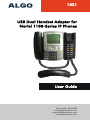
1
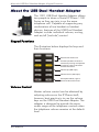
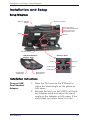
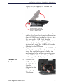
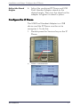
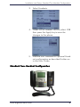
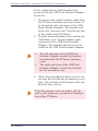
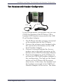
1021
USB Dual Handset Adapter for
Nortel 1100-Series IP Phones
User Guide
Document#: 90-00039
[email protected]
[email protected]
www.algosolutions.com
Algo 1021 USB Dual Handset Adapter User Guide
Table of Contents
About the USB Dual Handset Adapter ...................... 3
Keypad Functions......................................................
Volume Control ........................................................
Audio States .............................................................
Normal .................................................................
Mute......................................................................
Exclude..................................................................
3
3
4
4
4
4
Installation and Setup .............................................. 5
Setup Diagram ......................................................... 5
Installation Instructions ............................................. 5
Connect USB Dual Handset Adapter ...................... 5
Connect USB Cable................................................ 6
Adjust the Stand Angles .......................................... 7
Configure the IP Phone ............................................. 7
Standard Two-Handset Configuration ....................... 8
Two Handsets with Headset Configuration .............. 10
Regulatory Information .......................................... 11
About the USB Dual Handset Adapter: Keypad Functions
About the USB Dual Handset Adapter
The 1021 USB Dual Handset Adapter allows
two people to share a Nortel IP Phone 1100
Series so they can join in on the same
telephone call. Capable of supporting any
combination of two handset or headset
devices, features of the USB Dual Handset
Adapter include individual volume, muting,
and on/off ("exclude") control.
Keypad Functions
The illustration below displays the keys and
their functions.
Reserved for future use
Exclude (disables handset or
headset by muting microphone
& speaker); Light is ON when
Exclude Activated
Volume Up (4dB steps)
Volume Down (4dB steps)
Microphone Mute; Light is
ON when Mute Activated
Volume Control
Master volume control can be obtained by
adjusting volume on the IP Phone itself;
however, best practice is to use the volume
keys on the USB Dual Handset Adapter. The
adapter is designed to provide the same
audio range as the telephone controls when
the telephone volume remains at the default
level.
90-00039
3
About the USB Dual Handset Adapter: Audio States
Soft clicks are provided when pressing volume
keys until maximum or minimum level is
reached. The audio level settings will reset to
default after 60 seconds of silence to the
receiver.
Audio States
There are three audio states per user:
1. Normal
2. Mute
3. Exclude
Normal
In Normal mode, both the microphone and
the speaker are operational and the audio is
heard and transmitted normally. A high tone
is provided when entering Normal mode.
Mute
In Mute mode, the microphone is disabled,
preventing transmission of audio from the
user’s handset or headset. A medium tone is
provided when entering Mute mode. When
the Mute mode is active, the light on the Mute
key will be on.
Exclude
In Exclude mode, both the microphone and
the speaker will be disabled. A low tone is
provided when entering Exclude mode. In
addition, when the Exclude mode is active,
the light on the Exclude key will be on.
Note that Mute and Exclude modes are
mutually exclusive so pressing the Mute key
while in Exclude mode will switch to the
Mute mode and deactivate the Exclude
mode.
www.algosolutions.com
4
Installation and Setup: Setup Diagram
Installation and Setup
Setup Diagram
USB Dual Handset
Adapter
1100 Series IP Phone
Fasten connecting
arm of USB Dual Handset
Adapter to IP Phone
with supplied screws
Wheel
Tilt Lever
USB Connection
USB Dual Handset
Adapter Ports
IP Phone Ports
PC Port
Handset Port
Data Port
Power
Headset Port
Left Handset/
Headset Port
Right Handset/
Headset Port
Installation Instructions
Connect USB
Dual Handset
Adapter
90-00039
1. Press the Tilt Lever on the IP Phone to
adjust the stand angle on the phone to
fully open.
2. Release the latch on the USB Dual Handset Adapter stand and adjust the stand
angle on the adapter to fully open. If the
stand does not rotate freely, turn the
5
Installation and Setup: Installation Instructions
Wheel on the Adapter to release the
adjustment mechanism.
To open stand, push Tab
down to release latch while
lifting up at other end
3. At the back of the IP phone, remove the
rubber plug from the Accessory Expansion
Module (AEM) port and plug it into a similar port on the USB Dual Handset
Adapter. Note: although the AEM port is
not used, the plug’s removal is necessary
to physically mate the USB Dual Handset
Adapter to the IP Phone.
4. Align the connecting arm of the USB Dual
Handset Adapter behind the phone and
insert the supplied screws in to the top
and bottom holes of the connecting arm
of the USB Dual Handset Adapter. Tighten
until snug with a Phillips-type screwdriver.
Connect USB
Cable
5. Connect the
USB cable of
the USB Dual
Handset
Adapter to the
USB connector of the IP
Telephone.
www.algosolutions.com
6
Installation and Setup: Configure the IP Phone
Adjust the Stand
Angles
6. Adjust the combined IP Phone and USB
Dual Handset Adapter stands to the
desired angle. Then turn the wheel on the
adapter to tighten its stand in place.
Configure the IP Phone
The USB Dual Handset Adapter is a USB
device and the IP Phone must be set to
recognize it. To do this:
1. Double-press the Services key on the IP
Phone.
Services Key
2. Select Preferences.
90-00039
7
Installation and Setup: Standard Two-Handset Configuration
3. Select Headsets.
4. Under Active Headset Device, select USB
then press the Apply key to save the
changes to the phone.
5. Proceed with Standard or Optional Headset configuration as described further on
in this User Guide.
Standard Two-Handset Configuration
www.algosolutions.com
8
Installation and Setup: Standard Two-Handset Configuration
In this configuration, both handsets are
connected to the USB Dual Handset Adapter.
To do this:
1. Disconnect the coiled handset cable from
the IP Phone handset port and connect it
to the bottom left connector of the USB
Dual Handset Adapter. This handset will
be for the “primary user” and should rest
in the cradle of the IP Phone.
2. Plug the second handset to be used by the
"secondary user" into the bottom right
connector of the USB Dual Handset
Adapter. This handset should rest in the
cradle of the USB Dual Handset Adapter.
•
•
The left-side keys of the USB Dual
Handset Adapter control the handset
provided with the IP Phone ("primary
user")
The right-side keys of the USB Dual
Handset Adapter control the handset
for the secondary user.
3. When the secondary handset is not in use,
activate the Exclude key by pressing it one
time. The red light will illuminate when the
Exclude key is active.
Only the primary user can end a call. To
end a call, hang-up or press the Goodbye
key of the IP Phone.
90-00039
9
Installation and Setup: Two Handsets with Headset Configuration
Two Handsets with Headset Configuration
Headset
In this configuration, the primary user can use
ONLY the handset of the IP Phone; OR a
headset AND handset connected to the USB
Dual Handset Adapter.
1. The IP Phone handset remains connected
to the handset port of the IP Phone.
2. Connect the primary user's headset to the
left connector at the bottom of the USB
Dual Handset Adapter.
3. Connect a second handset for the secondary user to the right connector at the
bottom of the USB Dual Handset Adapter.
4. Press the Headset key of the IP Phone to
activate the USB Dual Handset Adapter in
this configuration. The light on the Headset key on the IP Phone will illuminate
when active. At this time, the headset and
the handset connected to the USB Dual
Handset Adapter will be active. The hand-
www.algosolutions.com
10
Regulatory Information: Two Handsets with Headset Configuration
set connected directly to the IP Phone will
be inactive.
Only the primary user can end a call. To
end a call, hang-up or press the Goodbye
key of the IP Phone.)
Regulatory Information
This device complies with Part 15 of the FCC Rules.
Operation is subject to the following two conditions: (1)
this device may not cause harmful interference, and (2)
this device must accept any interference received,
including interference that may cause undesired
operation.
NOTE
This equipment has been tested and found to comply
with the limits for a Class B digital device, pursuant to
Part 15 of the FCC Rules. These limits are designed to
provide reasonable protection against harmful
interference in a residential installation. This equipment
generates, uses and can radiate radio frequency energy
and, if not installed and used in accordance with the
instructions, may cause harmful interference to radio
communications. However, there is no guarantee that
interference will not occur in a particular installation. If
this equipment does cause harmful interference to radio
or television reception, which can be determined by
turning the equipment off and on, the user is
encouraged to try to correct the interference by one or
more of the following measures: reorient or relocate the
receiving antenna, increase the separation between the
equipment and receiver, connect the equipment into an
outlet on a circuit different from that to which the
receiver is connected, or consult the dealer or an
experienced radio or TV technician for help.
The user should not make changes or modifications not
expressly approved by Algo Communication Products
Ltd. Any such changes could void the user's authority to
operate the equipment.
90-00039
11
Algo Communication Products Ltd.
4500 Beedie Street
Burnaby, BC Canada V5J 5L2
www.algosolutions.com
Sales & Support:
Toll-free (USA or Canada): 1-877-884-2546
Or 1-604-454-3790
[email protected]
[email protected]