1
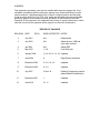
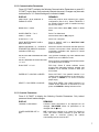
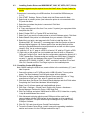
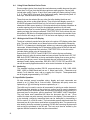
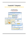
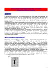
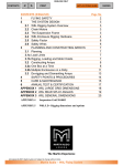
DP8 & DP9 DOCUMENT PRINTERS OPERATORS MANUAL 7860 AIRPORT HIGHWAY, PENNSAUKEN, NJ 08108 (856) 488-0700 (856) 488-0925 (FAX) WWW.CRADEN.COM DP8 & DP9 Operators Manual Table of Contents FUNCTIONAL SPECIFICATIONS 1 INSTALLATION & RESHIPMENT 3 RIBBON CARTRIDGE LOADING 3 KEYPAD & DISPLAY OPERATION 4 DOCUMENT INSERTION 5 CONFIGURATION Printer Parameters Communication Parameters Override Parameters Service Parameters 5 6 7 7 8 DIAGNOSTICS 9 SELF TEST & LOCAL PRINTING 9 ERROR CONDITIONS Document Jam Cover Open Page Overflow Carriage Fault Clear Eject Jam Narrow Document 9 9 10 10 10 10 DRIVERS Installing Craden Drivers on Windows 95 or 98 Installing Craden Drivers on Win NT, 2000, XP, Vista or 7 Installing Craden USB Drivers Using Printer Resident Device Fonts Writing to the Printer LCD Display 10 10 10 10 10 11 INTERFACING Input Buffer Operation Interface Protocols Interface Signals & Cables 12 12 12 13 PROBLEM SOLVING No Display or Blocks Displayed Unchangeable Configuration Parameters No Document Motion Carriage Fault or No Carriage Motion No Printing or Light Printing Ribbon Smear Erratic Document Feed, Mispositioning or Overprinting Rollers Run at Power-Up or After Document Ejected Erratic Character Spacing or Carriage Hitting End Stops Interface Inoperative Ribbon Shield Removal/Replacement Ribbon Shield Face Inspection 13 13 13 14 14 14 14 14 14 14 14 15 16 LUBRICATION AND CLEANING 17 RECOMMENDED SPARE PARTS 18 WARNING This equipment generates, uses and can radiate radio frequency energy and, if not installed in accordance with the instruction manual, may cause interference to radio communications. It has been tested with a Class A computing device and has been found to comply with Part 15 of FCC rules, which are designed to provide reasonable protection against such interference when operated in a commercial environment. Operation of this equipment in a residential area is likely to cause interference in which case the user at his own expense will be required to correct the interference. RECORD OF CHANGES REVISION DATE ECO’s PAGES AFFECTED NOTES 2 July 2001 ALL Reformatted 3 July 2002 ALL Added drivers, USB and quick start sections 4 Jan 2003 ALL Added DP9 5 May 2003 1, 6-8 Fast Draft print 6 January 2004 1-3, 6-10, 12, 13, 18 Updated 7 June 2004 8 Edge Sensor parameter 8 December 2004 3, 4, 9, 10, 16 Updated 9 December 2006 4, 5, 8 Updated 10 July 2007 10 thru 18 Deleted Programming section added Ribbon Shield section 11 December 2007 1 Updated 12 June 2010 10, 11 Updated DP8 & DP9 DOCUMENT PRINTERS - FUNCTIONAL SPECIFICATIONS 1.1 Print Characteristics Print Method 24-wire dot matrix impact, automatic thickness compensation Print Spacing 5, 6, 8.5, 10, 12, 17, 20 and 24 chars/inch Fonts 96 char. ASCII, international character set Windows True Type & graphics Print Speed (chars/second) Characters/inch 10 12 Dot Graphics 60,120,180, 360 dpi horizontal; 72, 180 dpi vertical Feed Speed 50 msec. single line feed at 5 or 6 lines/inch 12 inches/second (305 mm/sec) slew speed Feed Accuracy +/- 0.6% Ribbon Cartridge life DP8: 3 million characters, DP9: 5 million characters Correspondence 75 90 Normal 150 180 Draft 225 270 1.2 Document Characteristics Media Single sheets, multipart forms (up to 6), passbooks & envelopes Print Line Width DP8: 5.6” (142mm), DP9: 8.2” (208mm) Form Width 2.5” (64 mm) to 6.5” (165mm) in DP8 or 9.7” (246mm) in DP9 DP8: wider forms printable in landscape mode Form Height 2.5” (64 mm) minimum, no maximum Form Thickness 0.0035” (0.09 mm) to 0.062” (1.57 mm) Non-printable areas Top of form Above horiz. fold Below horiz. Fold Bottom of form Vertical fold/edge 0.16” (4.1mm) 0.38” (9.7mm) 0.30” (7.6mm) 0.45” (11.4mm) 0.25” (6.4mm) 1.3 Interface Standard Serial RS-232, 1200-38400 baud, 11KB buffer, dual ports on DP9 Command Sets IBM Proprinter/4722, Unisys and Craden Protocols DTR and Xon/Xoff Optional USB port, Parallel port Power Input 100-240 VAC, 43-63 Hz, 80 W max. 1.4 Physical Characteristics Dimensions DP8: 10.6” (269mm) wide, 7.2” (183 mm) deep, 7” (178 mm) high DP9: 13.8” (351mm) wide, 9.8” (249mm) deep, 7.2” (184mm) high Weight DP8: 11 pounds (5 kg) + 1.3 pounds (0.6kg) packing DP9: 14.4 pounds (6.5 kg) + 3.4 pounds (1.5 kg) packing 1.5 Environment & Standards Operating 10 to 40 C, 10 to 90% humidity Storage -30 to 70C, 5 to 95% humidity Standards UL 1950 & Canadian UL Listed FCC 20780 Class A certified IEC 950 & CE certified 1 2.0 INSTALLATION 2.1 Installation Procedure 1. Read 3.1 to 3.5.2 on Operation and Configuration. 2. Press the latches on the lower front cabinet sides & rotate the cabinet upwards. 3. Remove the foam blocks on each side of the carriage. 4. Install the ribbon cartridge (See 3.1) 5. Connect the interface cable. (See 3.11.3 for cabling information). 6. Check that the power switch on the printer rear is off (“0” side depressed). Connect the line cord between the printer and an electrical outlet. The printer accepts 110VAC to 240VAC nominal input. If a line cord was not supplied with the printer procure an IEC HAR line cord that has an IEC 320-C13 style connector and the appropriate HAR plug for your country. 7. Turn on the power switch. READY should be displayed. If the display is not legible adjust the contrast knob on top of the mechanism beneath the cabinet. 8. Configure printer and interface parameters (See 3.5-3.5.2) using 92 and 93 FUNCT. Common variations to the default settings are a higher baud rate for better throughput, EMULATION MODE I for Proprinter emulation and PROTOCOL = XON/XOF for software that does not use DTR hardware handshaking. Function 94 settings are factory set for a specific printer and should not be changed. 9. Perform a local print test (See 3.8) with 95 FUNCT. 10. If host printing is incorrect, check that 93 FUNCT Communication Parameters match the host parameters and review all 92 FUNCT Printer Parameters. 1 2 Push in on cabinet latches Rotate cabinet up and back. 4 Remove foam shipping blocks. RUBBER WHEEL 5 RIBBON PATH TABS Push ribbon guide plate tabs down. 2 3 Rotate lift ring forward to lift and lock carriage. 6 RIBBON SHIELD Slip ribbon over and behind guide plate tabs. Rotate cartridge into place and snap in. Rotate cartridge drive gear clockwise to align and take up ribbon slack. Push shield up. Lower carriage into operating position. Close cabinet. 2.2 Reshipment If possible, retain the original packing material for reshipment. If the original packing material is not used, insure that printer and the printer carriage will not move during shipment and that the printer has sufficient protective padding. 3.0 3.1 Operation Ribbon Cartridge Loading Our experience has found many “generic” ribbons causing printer malfunctions. Ribbon advance issues, poor print quality, smearing, and printhead failure have occurred. Please use Craden ribbons or carefully qualify generic ribbons. To replace a ribbon cartridge do the following and refer to drawings on page 2 and above: 1. Depress the cabinet latches on the lower front cabinet sides and rotate the cabinet upwards. 2. Pull the lift ring on the right side of the printer forward to lift and lock the carriage. 3. Push down the ribbon guide tabs on each side of the printhead to lower the ribbon shield. 4. Remove the old cartridge by pulling down on the top and rotate the top edge forward. 5. Guide the new ribbon behind the rubber wheel and between the printhead nose and ribbon shield. Insure the ribbon is not twisted. 6. Mount the new ribbon cartridge bottom edge first and rotate the top edge backwards. Turn the cartridge knob clockwise if needed to lock the cartridge in place. 7. Turn the cartridge knob clockwise to remove the ribbon slack. 8. Push the ribbon shield up and the lift ring backward to lower the carriage. Push down on the cartridge to insure that the carriage is fully seated. 9. Rotate the cabinet forward until the latches on both sides engage. Ribbon Cartridge Printhead Cartridge Clip Tabs Tabs Rubber Wheel Left Edge Guide DP8 Ribbon Fit, Sides Ribbon guide & shield Lift Ring DP9 printer with cabinet open, lift ring down and ribbon guide down DP9 Ribbon Fit, Sides 3 3.2 Keypad Operation EJECT: ejects an inserted document if the print buffer is empty. A: moves a document up 1/60" with each depression. If held depressed, the document will slowly move into the printer. Also initiates document insertion if the printer is configured for key rather than automatic insertion. (See 3.5.1) B: moves a document down 1/60" with each depression. If held depressed, the document will slowly move out of the printer. FUNCT: enters previously keyed digits as a function code. All function codes beginning with 9 are reserved for internal printer operations. All other function codes are transmitted to the host system and their usage is host defined. If no digits have been entered, FUNCT will override automatic alignment for one document. CLEAR: erases any previously keyed digits before they are transmitted to the host by the FUNCT or ENTER keys. ENTER: transmits previously keyed digits to the host system. All responses are host defined. This key also initiates document printing if the printer is configured to delay printing until the ENTER key is pressed (See 3.5.1). 0 to 9: 3.3 enter digits to be transmitted to the host by the FUNCT or ENTER keys. Key depressions appear on the lower display line. Display Operation The display has 2 lines of 16 characters each and is used to display messages both from the printer and the host system. There is a contrast knob to the left of the ribbon instruction/configuration label that should be adjusted for maximum legibility depending on the display viewing angle. When the printer is turned on, "READY" will be displayed. DP9 printers have lamps to identify dual port activity when DUAL PORT is set to Y (see 3.5.2). The lamp labeled “A” indicates the port closest to the printer’s left side is active and the lamp labeled “B” indicates the port closest to the printer’s right side is active. KEYPAD & DISPLAY PANEL If one of the green lights is on and there is no paper in the printer, there is more print pending. Insert paper and the printer will finish printing. 4 Document edge guide 3.4 Document Insertion Insertion procedures may be customized to satisfy varied applications and user preferences. (See Printer Parameters in 3.5.1). If auto alignment is enabled, gently insert the document upper left corner toward the point where the left edge guide and the feed rollers meet. Release the document when the rollers grip it and it will be automatically aligned and inserted to the first print line. Auto alignment may be disabled for an individual document by pressing the FUNCT key before insertion or for all documents by changing the SKEW CORRECT printer parameter. When auto alignment is disabled, the left document edge should be aligned to the left edge guide and then slid forward into the feed rollers which will insert it to the first print line. The PAUSE printer parameter may be set to delay when the rollers activate for a few seconds or until the A key is pressed. This allows more time to insert cumbersome documents or to train new users. With auto alignment enabled the printer should be configured for no delay. The DOCUMENT INSERT printer parameter may be set to move the document to the last (bottommost) rather than the first printable line. The BEGIN PRINTING printer parameter may be set to delay printing until ENTER is pressed. This allows the operator to insure that the document has inserted correctly. If not, it may be EJECTed and reinserted. 3.5 Configuration The printer may be configured from the keypad with all parameters saved in a non-volatile memory. There are 4 configuration categories: Configuration Category Press Printer Parameters Communication Parameters Override Parameters Service Parameters 9 2 then FUNCT 9 3 then FUNCT 9 9 then FUNCT 9 4 then FUNCT After accessing a category, each parameter will be displayed. Press A to display the next choice for the parameter or press ENTER to display the next parameter. If the display does not change when A is pressed, the keypad is locked. See 3.5.3 to unlock the keypad. 5 3.5.1 Printer Parameters Press 9 2 FUNCT to display the following parameters or press 9 0 0 FUNCT to print them on a previously inserted document. Changes may be made as described above. Before proceeding, see 3.4 and select the insertion sequence which best fits your application. Default settings are indicated in bold print. DISPLAY REMARKS LINES/INCH = 5 or 6 Select 5 or 6 lines per inch vertical spacing CHARS/INCH = 10, 12 or 17 Select 10, 12 or 17 characters per inch horizontal spacing. PRINT = DRAFT, NORMAL or CQ Select faster DRAFT, NORMAL, or slower but higher quality CQ print. DRAFT should not be used on passbooks and may degrade DP8 print quality in the rightmost printable column. QUIET MODE = Y or N Select Y for reduced noise on thin documents. Select N for darker print on thick documents. DOCUMENT INSERT = TOP or BOTTOM EDGE Select insertion to the TOP EDGE or BOTTOM EDGE of the document. DOCUMENT INSERT = WITH X SEC PAUSE or WITH A KEY Select automatic insertion 0, 1 or 2 seconds after placing a document in the input tray or delay insertion until A is pressed to allow more time for aligning documents. BEGIN PRINTING = IMMEDIATELY or AFTER ENTER KEY Select to begin printing IMMEDIATELY after the document insertion or delay printing until ENTER is pressed to verify proper alignment. LINE # 1 = .XXX Select the distance, between -0.80” and 0.80”, from the document top edge to the center of the first print line. Select 0.25” unless needing software compatibility with another printer. SKEW DETECTION = CORRECT SKEW, DETECT SKEW, or IGNORE Select CORRECT SKEW to automatically align skewed documents, DETECT SKEW to detect but not align skewed documents, or IGNORE to disable both skew detection and correction. SKEW DETECTION ALLOWED = .030, .050, .080, .110 or .130 Select the maximum skew per 4 inches of document width. Treatment of documents with excess skew is set by the next parameter. IF FORM SKEWED = ENTER/EJECT KEYS or AUTOMATIC EJECT If a document has excess skew, ENTER/ EJECT KEYS will continue printing if ENTER is pressed or eject the document if EJECT is pressed. AUTOMATIC EJECT will always eject a document with excess skew NOTE: Many Printer Parameters may be host configured with the HT or other commands. This allows for dynamic reconfiguration on a document by document or line by line basis. 6 3.5.2 Communication Parameters Press 9 3 FUNCT to display the following Communication Parameters or press 9 0 0 FUNCT to print them on a previously inserted document. Changes may be made as described in 3.5. Default settings are indicated in bold. DISPLAY REMARKS PROTOCOL = DTR, XON/XOF or PARALLEL INTRF. Select the protocol which matches your system configuration (See 3.12.2). Select PARALLEL if the parallel interface option is installed and skip the next four items. BAUD RATE = XXXX Select 1200, 2400, 4800, 9600, 19200 or 38400 baud. WORD LENGTH = 7 or 8 Select 7 or 8 bits/word. PARITY = XXXX Select EVEN, ODD or NO parity bit. STOP BITS = 1 or 2 Select 1 or 2 stop bits. INPUT BUFFER SINGLE LINE or MULTIPLE LINE Select a SINGLE LINE or a MULTIPLE LINE buffer of 11Kbytes. EMULATION MODE = C, I, EF4565 or EF4600/EFP95 (UNISYS emulation available on DP9 only) Select C to enable commands used with previous versions of this printer. Other selections enable commands compatible with popular PC based financial printers. AUTO FEED ON CARRIAGE RETURN = Y or N This selection available only when EMULATION MODE is set to a UNISYS mode. AUTO CARRIAGE RETURN ON FEED = Y or N Select Y unless compatibility with software written for another printer is needed. DUAL PORT = Y or N DP9 Only. Select Y unless software cannot accept ports alternating between enabled and disabled. If N is selected, connect to either port but not both. PAPER OUT = NO DOC or NEVER Select NO DOC if the parallel interface is to indicate paper empty whenever no document is in the printer or NEVER if it is never to indicate paper empty. SELECT = DOC PRES or ALWAYS Select DOC PRES if the parallel interface is to indicate off-line whenever no document is in the printer or ALWAYS to always indicate on-line 3.5.3 Override Parameters Press 9 9 FUNCT to display the following Override Parameters. Only trained personnel should make changes. DISPLAY REMARKS LOCKED or UNLOCKED LOCKED allows parameters to be displayed but not changed. UNLOCKED allows all parameters to be changed with the A key. COVER OVERRIDE OFF or ON OFF requires the cabinet to be closed for printing to occur. ON allows trained personnel to print with the cabinet open or removed. Closing the cabinet automatically sets the override OFF. 7 3.5.4 Service Parameters Press 9 4 FUNCT to display the Service Parameters in the following format. These parameters are factory selected specifically for each printer and recorded on the label behind the display inside the printer. They do not usually need to be modified by the user. CAUTION: CHANGE OF THESE PARAMETERS BY UNTRAINED PERSONNEL MAY RESULT IN INCORRECT PRINTER OPERATION. DISPLAY 8 REMARKS TOP OFFSET = XX Adjusts the uppermost print line location. Smaller values print closer to the top edge. LEFT OFFSET = XX Adjusts the carriage home location during document insertion. Larger values move the carriage to the left. LEFT MARGIN = XX Adjusts the first column print position if edge sensing is not installed (EDGE SENSOR parameter will not appear below). Larger values move printing to the right. CAR. ALIGN = XX Aligns lines printed right to left with lines printed left to right. Larger values move right to left printed lines to the left. FORWARD COMPENSATION = XX Adjusts distances moved down the document. Larger values increase the distance moved. REVERSE COMPENSATION = XX Adjusts distances moved up the document. Larger values increase the distance moved. EJECT HOLD OFFSET = XX Adjusts how much of the document is held in the feed rollers after it is ejected. Lower values hold less of the document. CONFIGURATION = XX Selects custom interface options. Select 00 unless indicated otherwise on the configuration label or incorrect operation may occur. GATE OFFSET = XX Sets the height of the alignment gate. Larger values raise the gate higher. NORMAL DARKNESS = -10 to 10 Adjusts darkness at normal print speed. Lower values reduce darkness and increase ribbon life. Select the lowest value that provides suitable legibility on thick forms. CQ DARKNESS = -10 to 10 Adjusts CQ print darkness. EDGE SENSOR = XX Adjusts the first column print position from the left paper edge. Larger values move printing to the right. SET SKEW VALUES SKEWCMP = -15 to 16 Value set by auto alignment skew sensor calibration. Compensates for right document sensor position relative to left document sensor. SET SKEW VALUES MID-SKEWCMP = -15 to 16 Value set by auto alignment skew sensor calibration. Compensates for middle document sensor position relative to left document sensor. PRINTHEAD TYPE Only displayed in early version DP8’s with later firmware installed. Set to match the printhead body color. Warning: A BLACK head can be damaged if set to SILVER. 3.6 Diagnostics 3.6.1 Power Up Diagnostics Diagnostics run automatically during power-up. If a fault is detected, ROM or RAM TEST BAD may be displayed. If a fault occurs, press A to advance to the next test. However, the printer should not be operated. If the problem is not a POWER FAILURE (see 3.9.1), consult your Service Personnel or Technical Manual. 3.6.2 Enhanced Diagnostics Diagnostics may be executed by pressing 9 0 FUNCT. If no faults exist, PROM REVISION XX, ROM TEST OK and RAM TEST OK will be displayed. If a fault exists, "BAD" will be displayed until A is pressed to advance to the next test. After ROM and RAM TEST, SENSORS LFBMRC will display. L is the left home carriage sensor; F and B are the front and back document sensors, M and R are the middle and right skew sensors and C is the cabinet open sensor. Any sensor that is covered will have its corresponding indicator erased. Each sensor may be activated to check for proper operation. Both operator indicator lights will turn on (DP9). Press A to conclude this test. 3.7 Self Test Insert paper and press 9 0 0 FUNCT to print the model, firmware ID and configuration settings. 3.8 Local Printing To print several variable length lines without host commands. Proceed as follows: 1. Insert a form and then press 9 5 FUNCT. 2. In response to CHAR LENGTH = 30, key in a two digit number of characters per line and then press ENTER. Insure that printing will not occur across a vertical fold or document edge. 3. In response to LINE COUNT = 01, key in a 2 digit number of lines. 4. Each time ENTER is pressed, that number of lines will be printed. 5. Press EJECT to eject the document and CLEAR to clear the display. 3.9 Error Conditions 3.9.1 Document Jam In the unlikely event that a document becomes jammed in the printer, printing will stop and "DOCUMENT JAM" will be displayed. The operator must clear the jam condition by moving the printhead left as far as possible and removing the document from the printer. 3.9.2 Cover Open If the printer cabinet is opened to replace a ribbon cartridge or clear a document jam, COVER OPEN is displayed and printing is disabled. Printing will resume 3 seconds after the cabinet is closed. 9 3.9.3 Page Overflow If the printer is commanded to move past the last printable line on a document it will eject the document and display PAGE OVERFLOW INSERT NEXT PAGE. Printing will resume when another document is inserted. 3.9.4 Carriage Fault The carriage could not move to the left margin and is probably caused by a jammed carriage or a bad left home sensor. 3.9.5 Clear Eject Jam At power up or when an eject command is executed and all document sensors do not uncover, “CLEAR EJECT JAM” will be displayed. Assure no document is covering the sensors and the sensors are clean. Turn power off before manually removing a jammed document. If no document is in the printer, the condition may be cleared by pressing the ENTER key while powering the printer on. If the condition will not clear there may be a sensor failure. 3.9.6 Narrow Document Not an error message. When a document less than 2.4” wide is inserted and the middle sensor does not “see” a document, NARROW DOCUMENT” is displayed and the operator can press ENTER to proceed or EJECT to abort. 4.0 Drivers (at the time of publication, 64-bit drivers are being developed and tested) CRADEN SUPPLIED DRIVERS ARE THE INTELLECTUAL PROPERTY OF CRADEN PERIPHERALS CORPORATION AND ARE PROTECTED BY COPYRIGHT LAW. THEY MAY ONLY BE USED WITH A PRINTER MANUFACTURED BEFORE APRIL 2000 IF ALLOWED BY A LICENSE AGREEMENT BETWEEN CRADEN AND THE USER OR THE USER'S SUPPLIER. DUPLICATION OF ANY PART OF THE DRIVERS IS ILLEGAL UNLESS ALLOWED BY A LICENSE AGREEMENT WITH CRADEN. 4.1 First Step for Installing Craden Drivers: Create a folder in the root directory (C:\) and label it cpcdrv. Copy into it the driver files from the CD or downloaded from the web site here www.craden.com/dd.htm The most up to date driver installation information is on the CD included with the printer or in the downloadable files as driver_readme.txt 4.2 Installing Craden Drivers on WINDOWS 95 OR 98: If the printer is connecting via a USB interface, first install the USB drivers. 1. Click START, Settings, Printers. Double click Add Printer 2. Select local unless the printer is not connected to this PC and click Next. 3. Click Have Disk. 4. In "Copy manufacturer's files from:" box, enter C:\cpcdrv\W95_W98 and click OK. 5. Select "Craden DP8" or "Craden DP9"and click Next. 6. Select the port where the printer is connected. Click Configure Port and insure that configuration matches the printer's 9 3 FUNCT parameters. Recommended port settings are 38400-baud, 8 data bits, no parity, 1 stop bit, and hardware flow control. Corresponding 9 3 FUNCT values are DTR, 38400, 8, NONE, 1, MULT, emulation I and auto CR on feed. Click Next. 7. Select Yes if you want the Craden printer to print all Windows output. Click Next. 8. Insert a page at least 5.8" wide and 6" high in a DP8 or 8.5 x 11” in a DP9. Click Finish to install the driver and print a test page. 10 4.3 Installing Craden Drivers on WINDOWS NT, 2000, XP, VISTA, OR 7 (32-bit): A firmware upgrade may be required to run the Vista/7 driver. Contact Craden for details. If the printer is connecting via a USB interface, first install the USB drivers per 3.11.3. 1. Click START, Settings, Printers. Double click Add Printer and click Next. 2. Select local or network printer (local unless the printer is not connected to this PC) and click Next. 3. Select the port where the printer is connected. Click Next. 4. Click Have Disk. 5. In "Copy manufacturer's files from:" box, enter C:\cpcdrv\(your op system folder here) and click OK. 6. Select "Craden DP8" or "Craden DP9" and click Next. 7. Select Yes if you want the Craden printer to print all Windows output. Click Next. 8. Select Shared if the printer is to be shared over your network. Click Next. 9. Select No to not print a test page and click Finish to install the driver. On Windows 2000, XP, Vista and 7, a message warns that the files do not have a Microsoft digital signature. All Craden specific files are data files that will be used by a standard Microsoft universal printer driver and will not affect system integrity. Click Yes to continue loading. 10. Insert an 8.5" by 11" page in a DP9 or at least a 5.8" wide by 6" high in a DP8. 11. Right click on the printer icon just installed and then left click on Properties, Ports and Configure Port. Insure that the configuration matches the printer's 9 3 FUNCT parameters. Recommended port settings are 38400-baud, 8 data bits, no parity, 1 stop bit, and hardware flow control. Corresponding 9 3 FUNCT values are DTR, 38400, 8, NONE, 1, MULT, emulation I and auto CR on feed. Click OK, General and Print Test Page to print on the installed printer. 3.11.3 Installing Craden USB Drivers: Note: Before loading the USB driver, create a folder in the root directory (C:\) and label it cpcusb. 1. Connect the printer to a PC USB port with a USB A-B cable. Turn on printer power. The New Hardware Found Wizard screen will then display. 2. Click Next to display Install Hardware Device Drivers and click next. In "Copy manufacturer's files from:" box, enter C:\cpcusb and click OK. 3. Click Next when Get Driver Files Search Results displays and click Finish when Completing the Found New Hardware Wizard displays. 4. Steps 2 and 3 will now repeat and install additional drivers. 5. Click Start > Settings > Control Panel. Double click System > Hardware > Device Manager. Double click Ports > USB Serial Port 6. Click Port Settings and select 38400 baud for DP8 or DP9, 8 data bits, no parity, 1 stop bit and hardware flow control. 7. Click Advanced to display which unused COM port will be used for all communication with the USB interface by any program or driver capable of driving a COM port. This port number may be changed to any other unused COM port if desired. 8. Click OK, OK, and close all open Control Panel windows. 9. To use the Craden Printer Driver, install it now per the preceding installation section and connect it to the COM port selected in step 7. 11 4.4 Using Printer Resident Device Fonts Printer resident device fonts should be used whenever possible because they print faster than TrueType fonts that Windows prints as raster graphics. Device fonts include letter quality Courier 10 and 12cpi, lower quality but faster printing Courier 5, 6, 17, 20cpi, NLQII 10cpi and 12cpi, and lowest quality, fastest printing draft 10 and 12cpi. Draft should not be used on passbooks. These fonts can be selected like any other font after loading the driver and selecting the printer as the default printer. They will print and display correctly in WYSIWIG programs like MS Word only if a font size is selected that displays characters at their correct spacing. A font size selection that displays characters at a smaller spacing will print slowly as the printhead repositions to print each character closer than its nominal spacing. MS Word curiously decreases character spacing as larger font sizes are selected. FONTTEST.DOC on the driver disk can be opened in MS Word or Wordpad and printed to demonstrate the resident fonts. Insure that the left margin is set to 0.2" for the fonts and display to read correctly. 4.5 Writing to the Printer LCD Display The driver includes 4 pseudo-fonts that write to the printer LCD display rather than print. The action that selects one of these fonts must be immediately followed by EXACTLY 16 characters to be displayed, without any intervening page positioning commands. All data following the 16 characters will be printed in the font that was selected before the pseudo-font selection. FONTTEST.DOC on the driver disk includes display writes using all 4 pseudo-fonts. Pseudo-fonts LCD TOP DLY and LCD BOT DLY write to the top and bottom display lines only after all previous data has been printed. Pseudo-fonts LCD TOP IMM and LCD BOT IMM write to the top and bottom display lines as soon as they are sent to the printer, even if all previous data has not yet been printed. The standard Craden display commands, ESC BEL, ESC FS, ESC DC3 and ESC GS, can still be used by applications able to write control characters to the printer. 5.0 Interfacing The standard interface provides RS-232 communications at 1200, 2400, 4800, 9600, 19200 or 38400 baud and has an 11 Kbyte input buffer. Characters may contain 7 or 8 data bits, even, odd or no parity and 1 stop bit. These parameters are all keypad programmable by 9 3 FUNCT. 5.1 Input Buffer Operation All data received except immediate status, display and reset commands are placed in an 11 Kbyte first-in, first-out buffer. Characters with parity errors are replaced by a "@" and framing errors are replaced by a “~”. The buffer may be used to receive all commands for printing an entire document. This reduces host attention to the printer but caution must be used to determine correct recovery from document jams and operator intervention during printing.If a document jams in the printer, printing stops and "DOCUMENT JAM" is displayed. The next status word transmitted will have the document jam bit set. Once notified, the host may write recovery instructions to the display. If the transaction is to be restarted, previously transmitted data can be destroyed by transmitting a DC4 in mode C or a CAN in mode I. The host should request status and check the document jam bit in the status word before re-transmitting data. The operator may also destroy the buffer contents by pressing CLEAR after removing the document and moving the printhead to the left wall. The host must then be notified by the operator that the transaction data may be re-transmitted. 12 5.2 Interface Protocols Either DTR or XON/XOF protocols may be selected from the keypad. In these modes the DTR signal will go false or a DC3 (Xmit off) will be transmitted if less than 1000 characters of space are available in the buffer when a CR or document movement command is received. Transmission from the host must then pause. DTR will later go true or a DC1 (Xmit on) will be transmitted when space becomes available and host transmission may resume. DTR is equivalent to most systems’ hardware protocol. 5.3 Interface Signals & Cables The interface provides for RS-232 communication. All signals are available on a 9 pin male connector equivalent to Cinch DB-9P. All connectors have 4-40 threaded inserts for positive mating. Pin assignments are as follows: Pin Signal 2 Transmit Data (TD) 3 Receive Data (RD) 4 Request To Send (RTS) 5 Signal Ground 6 Data Set Ready (DSR) 7 Clear To Send (CTS) 8 Data Terminal Ready(DTR) Description From printer, transmits printer status. To printer, receives data & commands. Connected to pin 6 for looping PC DTR to DSR Attached to printer logic ground. Connected to pin 4. To printer, enables status transmissions. From printer, indicates printer ready (and buffer available if DTR protocol is selected). The following cable connection will work correctly in most applications using PC type 25 or 9 pin serial ports. A shielded cable with ONLY one end of the shield connected to a metal connector cover or pin 1 of a 25 pin connector is recommended to increase immunity to static discharges and other electrical noise. Printer Pin PC-25 Pin PC-9 Pin Signal 3 2 3 Data to Printer 2 3 2 Data from Printer 6,8 5,6 6,8 DTR to PC CTS & DSR 5 7 5 Signal Ground Some applications do not allow DSR to be removed when the printer is busy. Use the following cabling with such software. Printer Pin 3 2 8 5 PC-25 Pin 2 3 5 6,20 7 PC-9 Pin 3 2 8 4,6 5 Signal Data to Printer Data from Printer DTR to PC CTS PC DTR to PC DSR Signal Ground 6.0 Problem Solving These are the most common printer problems that can be solved by an operator. More complete troubleshooting information is contained in the Technical Manual. If multiple printers are at one site, it can be useful to swap printers and cables to isolate a problem to a printer, cable or host. Printer (92 FUNCT) and Communication (93 FUNCT) parameters should be set the same for all printers. Service (94 FUNCT) parameters should be set per the label inside each printer. 6.1 No Display or Blocks Displayed If nothing appears on the display on power up, check that: 1. The power switch on the rear of the printer is ON. 2. The input power cord is plugged into both printer and supply outlet. 3. The contrast knob is adjusted for proper contrast. 4. The input power cord is plugged into a live supply outlet 13 6.3 No Document Motion If a document will not advance upon insertion: 1. Press EJECT if a previous document was manually removed without an eject. 2. Press A if configured for DOCUMENT INSERT WITH A KEY (see 3.5.1). 3. Use 9 0 FUNCT to check the front document sensor (see 3.6.2). 6.4 Carriage Fault or No Carriage Motion If the carriage will not move after a document is inserted: 1. Remove the foam packing blocks from both sides of the carriage. 2. Press ENTER if configured for PRINT AFTER ENTER KEY (see 3.5.1). 6.5 No Printing or Light Printing If no print noise occurs when the carriage traverses a document, check that the printhead is plugged into the carriage flex cable. If printhead noise is present, but no or light printing occurs: 1. 2. 3. 4. Correctly install the ribbon cartridge (see 3.1). Remove the cartridge and check for jammed ribbon. Check that the cartridge knob rotates as the carriage traverses. Check that QUIET MODE is off (see 3.5.1). 6.6 Ribbon Smear If there is ribbon smear on the document and it is not very wrinkled: 1. Check for too thick a document or printing too close to a fold or edge (see 1.2). 2. Check for a displaced or missing ribbon shield. 3. Replace the ribbon if it is wrinkled. Ribbon life may be increased by reducing the print darkness (see 3.5.4). 6.7 Erratic Document Feed, Mispositioning or Overprinting If feeding is erratic or preprinted forms are not correctly positioned: 1. Check for correct LINES/INCH (see 3.5.1). 2. Check that LINE #1 isn’t set to a negative “-” number (see 3.5.1). 3. Check that all service parameters are correctly set (see 3.5.4). 6.8 Rollers Run at Power-Up or After Document Ejected If the feed rollers continue to rotate when power is turned on or after a document is ejected, blow the document sensors (near the left end of the front rollers) free of dust and debris. 6.9 Erratic Character Spacing or Carriage Hitting End Stops If horizontal character spacing is erratic or forms are not correctly printed: 1. 2. 3. 4. 5. Check for correct CHARACTERS/INCH settings (see 3.5.1). Check that the ribbon cartridge is seated. Check that all service parameters are correctly set (see 3.5.4). If the carriage shaft has any residue build-up, clean it with a soft, dry cloth. With power off, check that the carriage moves freely by hand. 6.10 Interface Inoperative If the printer works in self test, but won't run from the interface: 1. Check for firm mounting of the interface cable to the rear panel. 2. Check for communication parameters set identically to the host system. 3. Check for correct interface wiring (see 3.11.3). 14 6.11 Ribbon Shield Removal / Replacement 1 2 Carriage Shaft Lifter Ring Open the cabinet, center the carriage and pull the lifter ring out and down to raise the carriage. Remove the ribbon cartridge. Lift the carriage shaft with one hand and pull the shield down and out to the right with the other. 3 4 Carriage Ribbon Guide Plate Shield Tips Tabs Pull the ribbon guide plate tabs toward you. Insert the new shield tips into the gap between the ribbon guide plate and the carriage 5 Push the shield up until it stops. Install the ribbon cartridge and lower the carriage. Rotate the shield until it is centered on the carriage. Do not let the shield tips slip behind the carriage. 6 Move the carriage lifter ring up and in to lower the carriage. Close the cabinet turn the printer on and do a test print or transaction. 15 6.11.1 Ribbon Shield Face Inspection The ribbon shield prevents ribbon fabric from rubbing on and smearing printed documents. It is a consumable. A high percentage of printers sent to Craden for repair has a ribbon shield that has reached end of life and is the primary cause of the printer’s problem. Document jams, damaged documents, streaking, poor print quality, and document skewing can often be alleviated by replacing ribbon shields after four to five ribbon replacements. Below is a guide to assist in ribbon shield inspection. New ribbon shield. Face is smooth, no defects Ribbon shield at end of life. Face is scored. There is no visible damage to the six-sided opening but a breech is imminent. This shield may begin to snag documents. Damaged ribbon shield. There is a breach in the six-sided opening. This ribbon shield will streak and tear documents. Damaged ribbon shield. One side of the six-sided opening is missing. This ribbon shield will streak and tear every document and may scratch the platen. The angle between the face and base (back) of the ribbon shield must be perpendicular. Ribbon shields are made of thin stainless steel and if bent can cause poor print quality or snag the ribbon fabric. 16 7.0 Lubrication And Cleaning 8.1 Lubrication There are no lubrication points in the printer. All parts are either permanently lubricated or are designed to operate dry. No lubricants should be used. They may adversely affect operation. 7.2 Document Feed Roller Cleaning 1. Open the cabinet. 2. Moisten a lint-free cloth with isopropyl alcohol and wipe the front rollers while rotating the gear on the end of the roller shaft. Do not use any strong solvents in place of alcohol. 3. Clean the rear rollers the same way. Make sure rollers are dry and residue free. Left (Home) Sensor Front Sensor Back Sensor Middle Sensor Right Sensor 7.3 Sensor Cleaning Clear sensor light paths of paper, paper dust and other obstructions if rollers continue to run when no document is present or other sensor problems occur. Insert the flexible nozzle tube of a compressed air can under the input guide and near each document sensor. Clear each sensor area with a short burst of air. 7.4 Document Print Area Cleaning Accumulated paper dust should occasionally be removed from the platen, printhead, carriage shaft, feed rollers, document sensors and other document path areas with brush, vacuum or compressed air. 7.5 Cabinet Exterior Cleaning The cabinet can be cleaned with a damp cloth and a mild, liquid soap or detergent. Do not use harsh, abrasive cleaners. 17 8.0 Recommended Spare Parts Machine Population: 1 10 25 50 100 250 Class A Spares Qty: Class B Spares Qty: Class C Spares Qty: 1 1 1 2 1 1 3 2 1 5 3 2 10 5 3 DESCRIPTION PART# Class A: Ribbon Shield Printhead Assy Main PCB Assy Sensor PCB Assy Technical Manual 73813-1 73812-1 72135-1 (-2 if with USB option) 72132-1 99090 Class B: Alphanumeric Display DP8 Keypad Assy DP9 Keypad Assy Power Supply Assy Edge Sensor PCB Assy 53025 72133-1 72133-2 72137-1 72155-1 Class C: DP8 Printhead Cable Assy DP9 Printhead Cable Assy DP8 Carriage Belt Assy DP9 Carriage Belt Assy Document Drive Belt 90T080P Motor Assy 72142-1 72142-2 73805-1 73805-2 67351 73820-1 The DP8 and DP9 use the same recommended spares except for the printhead cable, keypad assembly and carriage belt. 18