1
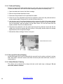
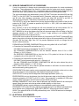
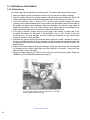
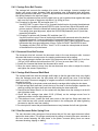
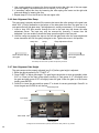
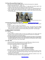
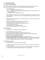
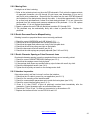
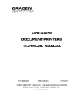
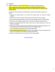
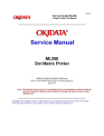
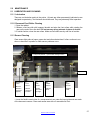
5.0 MAINTENANCE 5.1 LUBRICATION AND CLEANING 5.1.1 Lubrication There are no lubrication points in the printer. All parts are either permanently lubricated or are designed to operate dry. No lubricants should be used. They may adversely affect operation. 5.1.2 Document Feed Roller Cleaning 1. Open the cabinet. 2. Moisten a lint-free cloth with isopropyl alcohol and wipe the front rollers while rotating the gear on the end of the roller shaft. Do not use any strong solvents in place of alcohol. 3. In similar fashion, clean the rear rollers. Make sure all rollers are dry and free of residue. 5.1.3 Sensor Cleaning Clear sensor light paths of paper, paper dust and other obstructions if rollers continue to run when no document is present or other sensor problems occur. L - Left (Home) Sensor – synchronizes carriage motion Input Guide MultiSensor Cable Must be seated in connector properly FFront Sensor BBack Sensor MMiddle Sensor RRight Sensor Senses document insertion Senses document top edge Detects skew Detects skew 1. Insert the flexible nozzle tube of a compressed air can under the input guide and near each of the document sensors. Clear each sensor area with a 5-second burst of air. 27 Back to Table of Contents 5.1.4 Printhead Cleaning Perform if printwires stick when printing begins or print quality becomes intermittent. Be sure to check the ribbon first! The 73297-8 Printer Cleaning Kit contains all necessary tools. 1. Open the cabinet and remove the ribbon cartridge. 2. Remove the printhead attachment screw. 3. Disconnect the printhead from the printhead flex cables. 4. Clean the tip of the printhead nose where the printwires extend from the printhead with an alcohol wetted napkin. Remove all ink and bits of ribbon fabric lint. 5. Use the blunt end of a printhead cleaning brush to remove the bulk of the grease packed around the printwires. Then wet the brush end with alcohol to remove the rest of the grease from the printwires. Wipe the grease, ink and ribbon fabric “lint” from the brush onto the napkin provided. Remove all residual alcohol 6. Reconnect the printhead to the flex cables and remount the printhead. Insure that the flex cables don‟t touch the carriage belt drive pulley or idler pulley bracket when the carriage approaches the left and right box flanges. 7. Reinstall the ribbon cartridge. Perform a test print. Printhead attachment screw DP8/9 carriage top view 5.1.5 Document Print Area Cleaning Accumulated paper dust should occasionally be removed from the platen, printhead, carriage shaft, feed rollers, document sensors and other document path areas with brush, vacuum or compressed air. 5.1.6 Cabinet Exterior Cleaning The cabinet can be cleaned with a damp cloth and a mild, liquid soap or detergent. Do not use harsh, abrasive cleaners. Back to Table of Contents 28 5.2 SERVICE PARAMETER SET-UP PROCEDURE It may be necessary to change service parameters that compensate for certain mechanical tolerances. These parameters are listed on a label inside the printer and may be changed if necessary by 94 FUNCT(see 3.5.4). If mechanical parts are replaced some parameters may have to be reset. New parameter values should be marked on the configuration label. The service parameters are determined by using 95 FUNCT local print and either 955 and 944 FUNCT or just 943 FUNCT as described below. Parameter values are changed with the A and B keys. After changing a parameter, use 95, and either 955 and 944 or just 943, to obtain new print samples. Re-measure all distances and re-adjust if necessary. TOP OFFSET is set so the distance from the top document edge to the center of the first line printed by 95 FUNCT is located as specified by LINE #1 = .XXX (.250 is the default factory setting) under 92 FUNCT. LEFT OFFSET is set so the carriage can still move leftward from its home position 0.01" to 0.02" (0.3 to 0.5mm) before it contacts the gate arm that raises the alignment gate. LEFT MARGIN is set so the distance from the left document edge to the left edge of the first character printed by 95 FUNCT is 0.20" (5.1mm) if edge sensing is not installed (EDGE SENSOR parameter will not appear below). CAR ALIGN is set so either the vertical strokes of H‟s printed by 955 FUNCT (firmware E9 and earlier) from right to left align with those printed left to right or the zeros printed by 943 FUNCT (firmware EA and later) align. See 5.4.2 for precise adjustment but do not change the belt tension unless necessary. FORWARD and REVERSE COMPENSATION are set using either 943 or 944 FUNCT: a. Procedure for firmware E9 and earlier (see 3.7) 944 FUNCT prints lines of overlapping X's and O‟s 10" apart. Set FORWARD COMPENSATION so that the distance between lines of X's is 10.00" (254mm) +/- 0.02” (0.5mm) Set REVERSE COMPENSATION so that the line of O's printed at the top of the page overlaps the line of X's within 0.02” (0.5mm). b. Procedure for firmware EA and later (see 3.7) 943 FUNCT prints line pairs with values of –4 through +4. Set both FORWARD and REVERSE COMPENSATION with the value whose line pair is closest to 10.00" (254mm) +/- 0.02” (0.5mm) EJECT HOLD OFFSET is set so that an ejected document is still held in the drive rollers but can be removed by pulling gently on it. CONFIGURATION selects certain custom operating features and should not be set to a value other than shown on the configuration label without contacting the factory. GATE OFFSET is set by the Auto Alignment Gate Height procedure (see 5.4.7) EDGE SENSOR is set so the distance from the left document edge to the left edge of the first character printed by 95 FUNCT is 0.20" (5.1mm). This parameter is available on DP8 serial number 182057 and higher and DP9 serial number 293501 and higher. NORMAL DARKNESS Lower values reduce darkness and increase ribbon life at normal print speed. Select the lowest value that provides suitable legibility on thick forms. CQ DARKNESS similarly controls darkness at correspondence quality print speed. PRINTHEAD TYPE (early DP8 only) adjusts print pulse timing for two different printheads that have different drive characteristics. Select AUTO DETECT unless serial number is below 81000. Then select BLACK or SILVER printhead body color. A BLACK head can be damaged if set to SILVER. 5.3 ELECTRICAL ADJUSTMENTS There are no electrical adjustments required. Back to Table of Contents 29 5.4 MECHANICAL ADJUSTMENTS 5.4.1 Printhead Gap Too large a gap causes light print and missing dots. Too small a gap causes ribbon smear. 1. Open the cabinet, raise the carriage with the lift ring and remove the ribbon cartridge. 2. Hold the ribbon shield at its corners between the shield face and shield base. Raise the ribbon guide plate and push the shield down and slide it to the right side to remove it. 3. Lower the carriage. Insert a narrow .015" (.38 mm) feeler gauge between the platen (printing surface) and printhead nose from the side of the printhead. Insure that the feeler is flat against the platen and completely under the printwires (not under the gap wheel or behind the printwires). The .015" feeler should just fit without raising the printhead but a slight resistance should be felt as the feeler slides below the printwires. 4. If the gap is incorrect, slightly loosen the two larger head screws on either side of the printhead that fasten the gap plate to the printhead. (Use a 5/16” wrench to hold the mounting nuts). The gap changes as these screws are loosened so only loosen them enough to be able to move the plate. 5. Decrease the gap by pushing the printhead down against the feeler. Increase the gap by rotating a screwdriver blade in the slot between the gap plate and the printhead Insure that the gap plate is centered around the printhead nose and tighten the screws. Recheck the gap per step 4. 6. Replace the ribbon shield by raising the carriage, sliding the shield from the side between the carriage and the ribbon guide plate until the shield slot is centered. Gently push the shield up until it snaps into place. 7. Mount the ribbon and use 95 FUNCT to print (See 3.8) and check print quality. Adjust the NORMAL and CQ DARKNESS parameters (see 5.2). Insert the feeler gauge from the side of the printhead. Be sure the feeler gauge passes under the printwires only. (Front roller and input guide removed for clarity) Back to Table of Contents 30 5.4.1.1 Ribbon Shield Removal / Replacement The ribbon shield prevents ribbon fabric from rubbing on and smearing printed media. It is a consumable. Replace the shield every four to five ribbon replacements or when it is damaged. Watch the video at www.craden.com/ribbonshield.wmv . 1 2 Carriage Shaft Lifter Ring Open the cabinet, center the carriage and pull the lifter ring out and down to raise the carriage. Remove the ribbon cartridge. Lift the carriage shaft with one hand and pull the shield down and out to the right with the other. 3 4 Carriage Ribbon Guide Plate Shield Tips Tabs Pull the ribbon guide plate tabs toward you. Insert the new shield tips into the gap between the ribbon guide plate and the carriage 5 Push the shield up until it stops. Install the ribbon cartridge and lower the carriage. Rotate the shield until it is centered on the carriage. Do not let the shield tips slip behind the carriage. 6 Move the carriage lifter ring up and in to lower the carriage. Close the cabinet turn the printer on and do a test print or transaction. 31 5.4.1.1.1 Ribbon Shield Face Inspection A high percentage of printers sent to Craden for repair has a ribbon shield that has reached end of life and is the primary cause of the printer‟s problem. Document jams, damaged documents, streaking, poor print quality, and document skewing can often be alleviated by replacing ribbon shields after four to five ribbon replacements. Below is a guide to assist in ribbon shield inspection. New ribbon shield. Face is smooth, no defects Ribbon shield at end of life. Face is scored. There is no visible damage to the six-sided opening but a breech is imminent. This shield may begin to snag documents. Damaged ribbon shield. There is a breech in the six-sided opening. This ribbon shield will streak and tear documents. Damaged ribbon shield. One side of the six-sided opening is missing. This ribbon shield will streak and tear every document and may scratch the platen. The angle between the face and base (back) of the ribbon shield must be perpendicular. Ribbon shields are made of thin stainless steel and if bent can cause poor print quality or snag the ribbon fabric. Back to Table of Contents 32 5.4.2 Carriage Drive Belt Tension The carriage belt connects the carriage drive motor to the carriage. Incorrect carriage belt tension can cause uneven character width and spacing, poor bi-directional print alignment, stalling and premature belt wear. Tension is adjusted with the screw fastening the carriage belt idler pulley bracket to the right box flange. 1. Loosen the adjustment screw until the upper belt run can be pushed down against the lower belt run at the center of the printer with about 1 lb. (400g) of force. 2.a. Procedure for firmware „E9' and earlier (see 3.7) Use 955 FUNCT to print 4 lines of H‟s. Increase the belt tension by turning the adjustment screw 1/2 turn clockwise and press ENTER to print 4 more lines. Adjust belt tension and print as required. Select the loosest belt tension that gives good alignment of characters. If no setting gives good alignment, adjust the CAR ALIGN parameter (see 5.2) and then repeat this procedure. b. Procedure for printers with firmware „EA‟ and later (see 3.7) Use 943 function to print 6 lines of double-high double-wide zeros and select the best line of aligned characters. If none are desirable, increase the belt tension by turning the adjustment screw 1/2 turn clockwise and print using 943 FUNCT again. Select the loosest belt tension that gives good alignment of zeros. Press 94 FUNCT and ENTER 4 times. The display will read “CAR. ALIGN =” Use A or B to enter the value printed at the end of the selected line of printed zeros. 5.4.3 Document Drive Belt Tension The document drive belt connects the document motor to the rear document roller. Incorrect document belt tension causes uneven line spacing and document drive stalling. 1. Use a spring gauge to deflect the center of the document drive belt. Adjust only if an 8 oz. (225 gm.) force deflects the belt less than 0.02” (0.5 mm) or more than 0.04” (1 mm). 2. Loosen the 4 screws that fasten the document drive motor. 3. Move the motor toward or away from the rear document drive roller to adjust the tension and tighten the screws. Repeat step 1. 5.4.4 Carriage Shaft Cam and Shaft Rack The carriage shaft cam sets the carriage shaft height so that the gap wheel rises very slightly when the carriage moves onto the right platen end. Light printing can occur if the carriage shaft is too high. Document snagging or irregular movement of wide documents can occur if the shaft is too low. 1. Move the carriage to the printer center and raise the carriage while holding the box down. 2. If both carriage shaft ends don‟t touch the top of the slots in the box flanges, reposition the shaft by pushing the higher shaft end down while raising the lower shaft end. 3. Check that the rubber wheel is in firm contact with the platen when the carriage is at the left and right platen ends. 4. Check that the carriage rises about 0.010 (0.25mm) as the carriage moves from its rightmost position onto the right platen end. 5. If this does not occur, loosen the shaft cam screw on the right box flange and rotate the cam. Hold the cam with a small screwdriver blade in the rectangular slot when tightening the screw to stop the cam from rotating. 6. Do a test print to insure that print darkness does not vary between the left and right sides. 5.4.5 Rear Document Roller Spring Force The rear document roller springs are formed wires that pull the rear upper document rollers against the lower rollers. The springs are adjusted by raising or lowering the cams mounted on the front screws fastening the side plates to the platen. Incorrect spring force can cause document skewing, slipping or stalling. Back to Table of Contents 33 1. Use a spring gauge to measure the force required to raise the right end of the rear upper roller very slightly. It should measure 6 to 8 ounces (170 to 225 gm). 2. If necessary, adjust this force by loosening the roller spring cam screw on the right side plate and raising or lowering the cam. 3. Repeat steps 2 & 3 on the left end of the rear upper roller. 5.4.6 Auto Alignment Gate Ramp The gate ramp is properly adjusted if the screws that mount the roller springs to the gate have about 0.02” (0.5mm) clearance to the bottom of the side plate slots when the gate arm is at rest against the left side plate stop. Field adjustment is usually unnecessary. If it is necessary: 1. Insert a long 3/32 Allen wrench through the slot in the input tray and loosen the ramp adjustment screw. The input tray may be removed by removing 3 screws from the baseplate if you are unable to locate the ramp screw through the input tray slot. 2. Hold the ramp arm against the stop on the left side plate and move the ramp adjustment screw toward the left until the gate just begins to rise. Tighten the screw in this position Ramp Arm Ramp Ramp Adjustment Screw Move ramp this way to raise gate Move ramp this way to lower gate View: Ramp arm from front of printer with input tray removed 5.4.7 Auto Alignment Gate Height The gate ramp must be properly adjusted (see 5.4.6) before gate height is adjusted. 1. Raise the gate by pressing 9 4 7 FUNCT A. 2. Press FUNCT to adjust gate height. The gate fingers should be as close as possible (within 0.02” or 0.5mm) to the input guide without touching it. Each press of A will slightly raise the gate and each press of B will slightly lower the gate. When the gate is at the correct height, press ENTER. 3. Press B to lower the gate and then press A to check for correct gate height. Press B to lower the gate and CLEAR to exit the test. Roller Segments Input Guide Roller Shaft Gate fingers Looking into the document drive. Input tray removed for clarity. Gate in “up” position 34 5.4.8 Front Document Roller Spring Force Gate travel must be properly adjusted (see 5.4.7) before roller spring force is adjusted 1. Raise the gate by pressing 9 4 7 FUNCT A. 2. Rotate a lower drive gear to manually feed an ½” wide strip of the thinnest paper used (usually a receipt copy) under the rightmost front upper roller segment. 3. Adjust the right side roller spring tensioning screw so there is a very light drag from the roller on the paper while rotating a lower drive gear. Clockwise adjustment increases drag. 4. Repeat steps 2 and 3 for the leftmost roller segment and the roller spring tensioning screw on the left side plate. Roller spring tensioning screw (2) 5.4.9 Auto Align Skew Sensor Calibration (see the video at www.craden.com/skewsensor.wmv ) This procedure calibrates the relative position of the 3 skew sensors with a known square document 1. Press 9 4 6 FUNCT to display “Skew Calibration”. 2. Insert a document with known square top and left edges. If the document inserts straight and its top edge is parallel to the input guide edge, press ENTER to calibrate the skew sensors and exit. If the document did not insert perfectly, press EJECT and insert again. 5.5 REPLACEMENT PROCEDURES 5.5.1 Cabinet 1. Turn off power 2. Insert a small flat screwdriver blade in the slot in the middle of the rear cabinet edge and pull down to flex and remove the hinge wire that fastens the cabinet to the mechanism. 3. Press the cabinet latches and lift off the cabinet. 4. To install the cabinet, raise the rear panel heatsink and place the cabinet on the baseplate so that the latches fasten. Insert one end of the hinge wire through the box flange and into the cabinet hinge plate. Flex the wire and insert the other end through the other box flange and hinge plate so that the wire snaps straight. 5.5.2 Main PCB 1. Record all FUNCT 92 and 93 parameters so the new PCB can be configured correctly. 2. Disconnect the interface cable and remove the cabinet (See 5.5.1) 3. Disconnect the following cables from the Main PCB: J1 DC power J11 keypad J2 document motor J12 display J3&4 printhead J13 edge sensor (if installed) J5 document motor J15 home & document sensors J9 DP9 dual port J17 parallel port (if installed) 4. Remove the 5 screws fastening the Main PCB to the rear panel heatsink. 5. To replace the PCB, reverse the procedure in steps 2 to 4. Insure that the spacers remain on each mounting boss and that the 4 screws are tight. Use the longer screw to fasten the transistor and finned heatsink. 6. Reconfigure the new PCB with the FUNCT 92 and 93 parameters recorded in step 1 and the FUNCT 94 parameters listed on the configuration label. Back to Table of Contents 35 5.5.3 Sensor PCB 1. Turn off power and disconnect the flex cable from the sensor PCB. 3. Remove the two nuts fastening the PCB to the input guide. 4. Raise the upper front roller and remove the PCB by pushing it to the rear. 5. Install the lower (thick) sensor insulator, the new PCB and the upper (thin) sensor insulator. 6. Push the PCB and insulators forward, fasten the nuts and reconnect the flex cable. 7. Adjust TOP, LEFT OFFSET, LEFT MARGIN and EJECT HOLD parameters so that inserted documents are correctly positioned (See 5.2). Record new values on the parameter label. 8. Calibrate the skew sensor (See 5.4.9). 5.5.4 Keypad 1. Turn off power and remove the cabinet (See 5.5.1). 2. Place the mechanism upside down so it rests on the box and keypad bracket. 3. Remove the nuts fastening the keypad to the bracket. 4. Disconnect the flex cable and remove the keypad. 5. To install a new keypad reverse the procedure in steps 1 to 4 5.5.5 Display 1. Turn off power and remove the cabinet (See 5.5.1). 2. Place the mechanism upside down so it rests on the box and keypad bracket. 3. Remove the nuts fastening the display to the bracket. 4. Pull the flex cable connector cover away from the connector to disconnect the flex cable. 5. To install a new display reverse the procedure in steps 1 to 4 5.5.6 Power Supply PCB 1. Disconnect the AC power cord and remove the cabinet (see 5.5.1) 2. Raise the insulator flap covering the Power Supply PCB and disconnect the AC and DC connectors from the PCB. 3. Remove the 4 screws fastening the PCB to the box and remove the PCB. 4. Position the mechanism so that it rests on the keypad bracket and input tray. 5. Put the screws into the new PCB. 6. Insure that the insulator stays located around each mounting boss while mounting the new PCB and fasten the screws. 7. Reconnect the AC and DC connectors (the AC connector mounts to the end of the header labeled “L” on the PCB). 8. Insure that the insulator flap separates the power supply from the flex cables. 5.5.7 Carriage Motor 1. Remove the cabinet (see 5.5.1). 2. Disconnect the carriage motor from J5 of the Main PCB. 3. Remove 3 screws from the motor (shaft side) that fasten it to the box. Guide the carriage belt off the motor pulley (do not loosen the belt tensioner or you will have to readjust it) and remove the motor. 4. Transfer the motor pulley to the new motor. Leave a .01" (0.2mm) gap between the pulley hub and the motor flange. 5. Install the new motor in the box, onto the carriage drive belt, and fasten with the 3 screws. 6. Connect the motor to J5 on the Main PCB and replace the cabinet. 7. Set the LEFT HOME, LEFT MARGIN and CAR ALIGN parameters (see 5.2). 8. Tension the carriage belt (see 5.4.2). 36 Back to Table of Contents 5.5.8 Document Motor 1. Remove the cabinet (see 5.5.1). 2. Disconnect the motor from J2 on the Main PCB. 3. Loosen the 1/16” Allen screw that fastens the document drive pulley to the motor shaft 4. Remove the motor mounting screws. Remove the drive pulley through the motor clearance hole in the right box wall and remove the motor from the side plate. 5. Install the new motor (leads exiting from the bottom) through the side plate and onto the drive pulley and belt. It is easiest to replace the motor mounting screws by holding them with pliers between the side plate and box wall and then fastening them with a screwdriver inserted through holes in the box wall. 6. Locate the drive pulley so it is in line with the driven pulley and fasten it to the motor shaft. 7. Tension the belt (see 5.4.3). 8. Connect the motor to J2 on the Main PCB and replace the cabinet. 5.5.9 Printhead 1. If a black bodied printhead is to be installed in a DP8, run 9 0 FUNCT to display the firmware revision which MUST be C1 or greater. A DP8 with A or B series firmware MUST be upgraded to at least C1 before a black bodied printhead can be used. 2. Open the cabinet, raise the carriage with the lift ring and remove the ribbon cartridge. 3. Hold the ribbon shield at its corners between the shield face and shield base. Raise the ribbon guide plate and push the shield down and slide it to the right side to remove it. See picture in 5.4.1 4. Remove the printhead attachment screw. See picture in 5.1.4. 5. Disconnect the printhead from the printhead flex cables. 6. Connect the new printhead to the flex cables and remount it. Insure that the flex cables don‟t touch the carriage belt drive pulley or idler pulley bracket when the carriage approaches the left and right box flanges. 7. If possible, reset the printhead gap (see 5.4.1). 8. Replace the ribbon shield and cartridge. 9. For DP8‟s only, run 9 4 FUNCT. If the PRINTHEAD TYPE parameter appears after CQ DARKNESS, set it to match the printhead body color. A BLACK head can be damaged if set to SILVER. 10. Adjust LEFT OFFSET, NORMAL and CQ DARKNESS (see 5.2). 5.5.10 Carriage Drive Belt 1. Loosen the screw fastening the belt clamp to the carriage and remove the belt clamp. 2. Remove the screw fastening the carriage belt idler pulley to the right box flange. The belt and idler pulley are replaced as an assembly. 3. Install the new belt and clamp it to the carriage. 4. Tension the carriage belt (see 5.4.2). 5. Set the LEFT OFFSET, LEFT MARGIN and CAR ALIGN parameters (see 5.2). 5.5.11 Document Drive Belt 1. Loosen the document motor mounting screws and push the motor toward the drive rollers. 2. Slide the belt off the rear roller pulley and remove the belt. 3. Install the new belt through the motor clearance hole in the right box wall and re-tension the belt (see 5.4.3). Back to Table of Contents 37 5.6 TROUBLESHOOTING 5.6.1 Basic Troubleshooting This procedure exercises everything in the printer except the interface to the host system. If any step is not successfully executed, refer to the corresponding troubleshooting section. 1. Turn on printer power. A) If nothing appears on the display, see 5.6.2. B) If < > BAD is displayed, replace the indicated component on the main PCB or the complete main PCB. C) If CARRIAGE FAULT is displayed, see 5.6.6. 2. Press 12345678 and then CLEAR. Each number should appear in the display and then all should disappear. If this does not occur or if diagnostics don't begin to execute in the next step, see 5.6.3. 3. Execute 90 FUNCT diagnostics (see 3.6.2) and exercise the 7 sensors. If any sensor does not operate, see 5.6.4. 4. Execute Local Printing (see 3.8) and use a 6" x 11" document. A) If a document will not load into the printer, see 5.6.5. B) If the carriage will not move across the document, see 5.6.6. C) If no printing occurs, see 5.6.7. D) If print quality is not acceptable, see 5.6.8. E) For other possible problems, see 5.6.9. through 5.6.12 5.6.2 No Display If nothing appears on the display on power up, check that: 1. The power switch on rear of printer is ON. 2. The input power cord is plugged into both printer and supply outlet. 3. The contrast knob to the left of the configuration label is set for good display contrast. 4. Input power is present on the input power cord. 5. The fuse on the Power Supply PCB is good. 6. The display cable is attached to the display and to the main PCB J11. 7. 38 VDC is present between main PCB J1 pins 1 and 5. If not, check for AC line voltage at the Power Supply PCB input. If AC is present but 38VDC is not, replace the Power Supply. 9. If 38 VDC is present replace either the main PCB or the display module. 5.6.3 Defective Keypad If keypad depressions are not sensed proceed as follows: 1. If a single key fails but all others are OK, just that key may be replaced after the keypad is removed (see 5.5.4). 2. If a row or column of keys all fail, a key may be permanently depressed or the problem is in the cable between the main PCB and the keypad or on the main PCB. Back to Table of Contents 38 5.6.4 Defective Sensor All sensors transmit infrared light and sense light reflected by a document, gap roller or cabinet. The sensors are automatically re-calibrated each time the printer powers on. First check that the flex cable is firmly seated in the connector on the Sensor PCB. Press 9 0 FUNCT to run diagnostics and display “SENSORS” and the letters LFBMRCE. L is the left home carriage sensor; F and B are the front and back document sensors, M and R are the middle and right skew sensors, C is the cabinet open sensor and E is the document edge sensor. The cabinet open sensor is mounted on the main PCB and looks through a slot in the rear panel heat sink. The document edge sensor is mounted on the carriage and “looks” down toward the platen. All other sensors are mounted on the multi-sensor PCB (See picture in 5.1.3). Any sensor that is covered will have its corresponding indicator erased. Each sensor may be activated to check for proper operation. Press A to conclude this test. Place an object in any sensor‟s light path to remove the corresponding sensor letter from the display. Press ENTER to return to READY status. Symptom Rollers run continuously before a document is inserted and no “F” on display during 90 FUNCT. Rollers run continuously after a document is ejected and no “B” on display during 90 FUNCT. Carriage drives into the left side of the printer. Condition Front sensor light path is blocked by paper, paper dust, or a bent input guide. A sensor may be bent out of position. Back sensor light path is blocked by paper, paper dust, or a bent input guide. Sensor may be bent out of position. 94 FUNCT parameters are incorrect Disconnected sensor cable Defective left “home” sensor. Display reads “Cover Open” even when cabinet is closed Cover sensor cannot “see” reflective dot on inside of cabinet. Remedy Clear front sensor light path of paper scraps or blow sensor area with compressed air. Clear back sensor light path of paper scraps or blow sensor area with compressed air. Check 94 FUNCT parameters against label under the cabinet behind the alphanumeric display. Reinsert sensor cable Replace multi-sensor PCB Override cover sensor using 99 FUNCT (3.5.3) or replace reflective foil dot 5.6.5 No Document Motion If a document will not advance upon insertion: 1. Press EJECT if the previous document was manually removed without an eject command. 2. Press A if configured for DOCUMENT INSERT WITH A KEY (see 3.5.1). 3. Check that the drive belts are on their pulleys and the pulleys are tight on their shafts. 4. Check that the motor cable is seated onto J2 of the main PCB. 5. Remove the connector cover and check that the four motor leads are seated in their individual connector slots. 6. Measure about 6 ohms resistance between pins 1 and 2 and between 3 and 5 of the motor connector. If not, replace the motor (see 5.5.11). 7. Repair or replace the main PCB with a bad U1 or U2 driver circuit. 5.6.6 No Carriage Motion If the carriage will not move at power-up (CARRIAGE FAULT) or after a document is inserted: 1. Check that the flex cable is firmly seated in the connector on the Sensor PCB. 2. Check that the shipping blocks fastening the carriage have been removed. 3. Press ENTER if configured for PRINTING AFTER ENTER KEY (see 3.5.1). 4. Check that the motor cable is seated onto J5 of the main PCB. 5. Remove the connector cover and check that the four motor leads are seated in their individual connector slots. 6. Measure about 6 ohms resistance between pins 1 and 3 and between 4 and 5 of the motor connector. If not, replace the motor (see 5.5.10). 7. Repair or replace the main PCB with a bad U6 or U7 driver circuit. Back to Table of Contents 39 5.6.7 No Print or Light Print If there is no printhead noise when the carriage traverses a document: 1. Check that the printhead is plugged into the carriage flex cables. 2. Check that the flex cables are plugged into the main PCB J3 and J4. 3. Replace timer U13 or MOSFET Q7 on the main PCB. 4. Repair or replace the main PCB with a bad driver circuit. If there is printhead noise but there is no print or light print: 1. Correctly install the ribbon cartridge (see 3.1) or replace it if worn out. 2. Remove the cartridge and check for jammed ribbon. 3. Check that the cartridge knob rotates as the carriage traverses. 4. Check that QUIET MODE is turned off under 92 FUNCT. 5. Check the NORMAL and CQ DARKNESS parameters (see 3.5.4) 7. Check the printhead gap at both ends of the platen(see 5.4.1). 8. Clean the printhead (see 5.1.4). 9. Check that the carriage flange that clamps the drive belt is not bent down. 10. Check that the ribbon shield is pushed up until it clicks into place 5.6.8 Print Quality Symptom Condition Print not dark enough on receipts or multipart forms. Ribbon needs replacement Ribbon installed incorrectly Increase print darkness setting Streaking or smearing over printed lines. Ribbon installed incorrectly Ribbon shield is missing/damaged Ribbon is near end of life. Ribbon has too much ink. Generic ribbon installed Ribbon fabric is folded or twisted. Ribbon installed incorrectly Generic ribbon installed Printhead or printing circuit is defective (unusual). Racked carriage shaft or misadjusted shaft cam Ribbon installed incorrectly Ribbon shield is damaged Generic ribbon installed Ribbon shield is damaged Large gaps in printing or sporadic light print occurs. A row of dots is missing Print is darker on one side than on the other Ribbon getting tangled in printer Documents being torn Remedy Replace ribbon cartridge. See page 5 for ribbon installation See “DARKNESS” service parameters 3.5.4 See page 3 for ribbon installation Replace ribbon shield. Replace ribbon cartridge. Replace with Craden ribbon Replace ribbon cartridge. See page 3 for ribbon installation Replace with Craden ribbon If unusable, initiate a service call If unusable, initiate a service call See page 3 for ribbon installation Replace ribbon shield Replace with Craden ribbon Replace ribbon shield If print is light all across the print line, check as if printhead noise were present in 5.6.7. Print on a thick document will always be a little lighter than on a thin one. If there is ribbon smear on the document and it is not very wrinkled: 1. Check that document is not too thick or printing is too close to a fold or edge (see 1.2) 2. Check for a displaced or missing ribbon shield. 3. Check printhead gap (see 5.4.1). Back to Table of Contents 40 5.6.9 Missing Dots If a single row of dots is missing: 1. Refer to the printwire pinouts on the main PCB schematic. Pin 4 prints the uppermost dots of uppercase characters, pins 20 through 23 print lower case descenders (g,j,p,q and y) and pin 24 prints underscores. Disconnect the flex cable from the main PCB and measure the resistance of the bad printwire through the cable. It should be approximately 12 ohms for a silver body printhead and 6 ohms for a black body printhead. If it is not, remove the printhead from the carriage and measure resistance at the printhead. If it is OK, replace the flex cable. If it is not, replace the printhead. 2. Repair or replace the main PCB with bad driver transistor Q11 through Q33. 3. The printhead may be mechanically faulty with a bent or jammed wire. Replace the printhead. 5.6.10 Erratic Document Feed or Mispositioning If feeding is erratic or preprinted forms are not correctly positioned: 1. Check for correct LINES/INCH and LINE #1(see 3.5.1). 2. Check that all service parameters are correctly set (see 5.2). 3. Check that the upper feed rollers move freely in the side plate slots. 4. Check that all belt drive pulleys are tight on their shafts. 5. Check the document drive belt tension (see 5.4.3). 6. Check that the roller springs are properly adjusted (See 5.4.5 and 5.4.8). 5.6.11 Erratic Character Spacing or False Document Jams If horizontal character spacing is erratic or preprinted forms are not correctly printed: 1. Check for correct CHARACTERS/INCH settings (see 3.5.1). 2. Check that the carriage moves freely by hand. 3. If the carriage shaft shows any residue build-up, wipe it clean with a soft, dry cloth. 4. Check the carriage belt tension (see 5.4.2). 5. Tighten the drive pulley set screw on the carriage motor shaft. 5.6.12 Interface Inoperative If the printer works in self test, but won't run from the interface: 1. Check that the I/O cable is correct for your application (see 3.11.3) 2. Check for firm mounting of the interface cable. 3. Check for communication parameters set to match the host system (see 3.5.2). 4. Check for correct interface wiring (see 3.11.3). 5. Press 9 4 2 then FUNCT to print all previously received data immediately after the transaction. Control characters print as underlined lower case. 6. Check that CTS on I/O pin 7 is either not connected or is driven above +3V. 7. Replace the interface circuits in main PCB U14 and U15. Back to Table of Contents 41 5.6.13 Diagnostic Flowchart Use this flow chart to assist in troubleshooting. Is the display on the printer blank? Yes No Do the keys on the keypad work? See 3.2 for functions and exercise keys Yes No Will the printer take a document when it is placed into the machine? Yes No Power switch is ON Power cord plugged in both ends Contrast knob adjusted (3.3) Power outlet is live Is the keypad locked? (3.5.3) Press EJECT & CLEAR and try again Insert paper, press A key (see printer parameter, DOCUMENT INSERT, 3.5.1) Check sensors (5.6.4) Does the carriage move when printer should be printing? Open cabinet and override cover open sensor using 99 FUNCT (3.5.3) Yes No Does the printer print? Insert paper and press 900 FUNCT on the keypad (3.7) Yes No Is the printed output smearing? No Yes Is the printed output too light? No Yes Do the rollers run continuously, even when paper is not in the printer? Yes No Is the printed output spaced correctly? Yes No Does the printer communicate with the system when you send a transaction? End No Carriage Fault on display? Foam packing removed? Insert paper, press A key (see printer parameter, BEGIN PRINTING, 3.5.1) Ribbon correctly installed? (2.1) Ribbon shield installed correctly? (5.4.1.1) Remove ribbon, check for jammed cartridge Check that ribbon knob turns as carriage moves Ribbon correctly installed? Ribbon worn out? (2.1) Ribbon shield installed correctly? (5.4.1.1) Document too thick? (1.2) Printing in non-printable area of a document or passbook? (1.2) Ribbon correctly installed? Ribbon worn out? (2.1) Remove ribbon, check for jammed cartridge Ribbon shield installed correctly? (5.4.1.1) Quiet mode set to Y? Darkness set too low? (3.5.1, 3.5.4) Does the ribbon knob turn as carriage moves? Ribbon guide plate pushed up completely? (5.4.1.1) Paper dust or debris inside printer. (5.1.3) Blow out debris with compressed air. Multisensor cable seated correctly? (5.1.3) Characters per inch setting OK? (see printer parameter, LINES/INCH, 3.5.1) Check all service parameters. (3.5.4) Check interface cable mounting (pg. 44) Communication parameters match host system? (3.5.2) Back to Table of Contents 42 5.7 RECOMMENDED SPARE PARTS Machine Population: 1 10 25 50 100 250 Class A Spares Qty: Class B Spares Qty: Class C Spares Qty: 1 1 1 2 1 1 3 2 1 5 3 2 10 5 3 DESCRIPTION PART# Class A: Ribbon Shield Printhead Assy Main PCB Assy Sensor PCB Assy Cleaning Kit Technical Manual 73813-1 73812-1 72135-1 (-2 if with USB option) 72132-1 73297-8 99090 Class B: Alphanumeric Display DP8 Keypad Assy DP9 Keypad Assy Power Supply Assy Edge Sensor Assy 53025 72133-1 72133-2 72137-1 72155-1 Class C: DP8 Printhead Cable Assy DP9 Printhead Cable Assy DP8 Carriage Belt Assy DP9 Carriage Belt Assy Document Drive Belt 90T080P Motor Assy 72142-1 72142-2 73805-1 73805-2 67351 73820-1 The DP8 and DP9 use the same recommended spares except for the printhead cable, keypad, and carriage belt assys. 5.8 RECOMMENDED SERVICE TOOLS #1 and #2 Phillips Screwdrivers 3/16", 5/16" and 11/32" Open End Wrenches .050”, 1/16”, 5/64” and 3/32” Allen Wrenches .010” to .018” feeler gauges and a 1 lb. or 500 gm. Spring Gauge 6” scale calibrated in 1/100” 3/16” and 1/4” nut driver