1
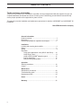
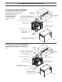
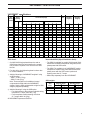
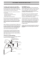
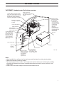
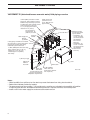
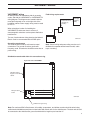
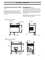
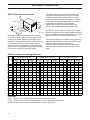
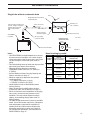
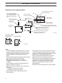
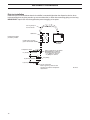
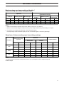
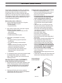
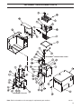
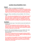
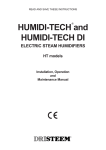
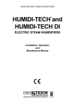
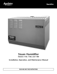
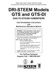
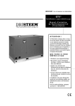
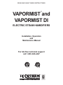
READ AND SAVE THESE INSTRUCTIONS ® VAPORMIST and VAPORMIST DI ELECTRIC STEAM HUMIDIFIERS Installation, Operation and Maintenance Manual For toll-free technical support call 1-800-328-4447 TABLE OF CONTENTS To the purchaser and installer Thank you for purchasing our VAPORMIST® humidifier. We have designed and built this equipment to give you complete satisfaction and trouble-free service for many years. Familiarizing yourself with this manual will help ensure proper operation of the equipment for years to come. This manual covers the installation and maintenance procedures for both the VAPORMIST and VAPORMIST DI humidifiers. DRI-STEEM Humidifier Company General information Product overview ................................................................. 3 Dimensions .......................................................................... 4 Electrical specifications, capacities and weights ................. 5 Installation Locating and mounting the humidifier .................................. 6 Piping ................................................................................... 6 Wiring .................................................................................. 9 Dispersion Using space distribution units (SDU-E and SDU-I) ..... 10 Using Single Tubes ..................................................... 13 Using a RAPID-SORB® dispersion panel .................... 15 Drip tee installation ..................................................... 16 Interconnecting piping tables ...................................... 17 Operation Start-up procedures ........................................................... 18 Control ............................................................................... 19 Maintenance Maintenance procedures ................................................... 20 Troubleshooting guide ....................................................... 23 Replacement parts ............................................................ 25 Notes ................................................................................. 31 Warranty ........................................................................... 32 2 VAPORMIST® HUMIDIFIER OVERVIEW Standard water models (VAPORMIST) The standard water VAPORMIST unit requires water conductivity of at least 100 µS/cm Electrical conduit (2 grains/gallon) to operate. It will not knockouts operate with water treated by reverse osmosis or 1½" (DN40) or 2" (DN50) flexible vapor hose, pipe or tubing connects deionization processes to dispersion tube(s) or to an SDU (see DI water model below). Water fill ¼" NPT (female) Condensate return line Duct Electrical area Keyholes for wall mounting INCOLOY alloy-sheathed immersion heaters Water fill access hole ¾" NPT (DN20) coupling, skimmer port and overflow drain Removable evaporating chamber Slide assembly under evaporating chamber provides easy removal for cleaning OM-82-4 Deionized water models (VAPORMIST DI) The VAPORMIST DI, shown here, is specifically designed for use with deionized or reverse osmosis water. Electrical conduit knockouts 1½" (DN40) or 2" (DN50) flexible vapor hose, pipe or tubing connects to dispersion tube(s) or to an SDU Duct Condensate return line Float cutoff switch Water fill ¼" NPT (female) Electrical area Keyholes for wall mounting INCOLOY alloy-sheathed immersion heaters Water fill access hole ¾" NPT (DN20) coupling, skimmer port and overflow drain Ball valve Removable evaporating chamber Slide assembly under evaporating chamber provides easy removal for cleaning OM-82-5 3 VAPORMIST® DIMENSIONS 24.2" (614 mm) Top view 2" (50 mm) 10.9" (276 mm) 2" (50 mm) 1" (25 mm) 2.25" (57 mm) Power wiring knockout Control or SDU wiring knockout Steam outlet Front view Left side view Venting 18.6" (472 mm) 2.25" (57 mm) 16.1" (409 mm) 1.50" (38 mm) 5.75" (146 mm) ¾" NPT (DN20) frame drain ¾" NPT (DN20) tank drain Bottom view 0.50" (13 mm) hole in base for water fill line 0.75" (19 mm) 0.63" (16 mm) 2.25" (57 mm) Power wire knockout 1.50" (38 mm) Control wiring knockout 5.75" (146 mm) 24.2" (614 mm) DC-1167 4 VAPORMIST® SPECIFICATIONS VAPORMIST specifications VM model number Steam capacity lbs/hr Current draw (amps) kg/h Single-phase kW Shipping weight ‡ Operating weight ‡ Three-phase 120V 208V* 240V* 480 † 600V † 208V* 240V † 480V † 600V † lbs kg lbs kg 2 6 2.7 16.7 9.6 8.3 4.2 3.3 -- -- -- -- 2 80 36 95 43 4 12 5.4 33.3 19.2 16.7 8.3 6.7 16.7** 14.4** 7.2** 5.8** 4 80 36 95 43 6 18 8.2 -- 28.8 25.0 12.5 10.0 25.0** 21.7** 10.8** 8.7** 6 88 40 122 55 8 24 10.9 -- 38.5 33.3 16.7 13.3 33.3** 28.9** 14.4** 11.5** 8 88 40 122 55 10 30 13.6 -- -- 41.7 20.8 16.7 29.1** 25.3** 12.6** 10.1** 10 93 42 139 63 12 36 16.3 -- -- -- 25.0 20.0 33.3 28.9 14.4 11.5 12 93 42 139 63 14 42 19.1 -- -- -- 29.2 23.3 38.9 33.7 16.8 13.5 14 93 42 139 63 16 48 21.8 -- -- -- 33.3 26.7 44.4 38.5 19.2 15.4 16 93 42 139 63 21 63 28.6 -- -- -- 43.8 35.0 -- -- 25.3 20.2 21 95 43 152 69 25 75 34.0 -- -- -- -- 41.7 -- -- 30.1 24.1 25 95 43 152 69 30 90 40.9 -- -- -- -- -- -- -- 36.1 28.9 30 101 46 156 71 34 102 46.3 -- -- -- -- -- -- -- 40.9 32.7 34 101 46 156 71 Table notes: Notes about SDUs (Space Distribution Units): * On 208V/240V/single-phase/three-wire and on 208V/three-phase/four-wire supplies, the neutral line provides a separate 120V circuit for the SDU fan unit. • The SDU-I is available for models VM-2 through VM-8, and all VM-10 models except those using 240V, threephase power with SSR control. ** For wire sizing, the highest leg draw is shown due to current imbalance. † Add the following to VAPORMIST weights if using an SDU option: – SDU-I: 12 lbs (5.5 kg) – SDU-E: 9 lbs (4 kg) Note: These weights are for additional control components housed within the VAPORMIST cabinet. See the SDU weights table at right for SDU weights (shipped separately). ‡ Add the following if using the SSR option: – For single-phase or three-phase models drawing less than 21.7 amps, add 2 lbs (1 kg) – For three-phase models drawing more than 21.7 amps, add 4 lbs (2 kg) • The SDU-E is available for all VAPORMIST models except those models using 240V/480V/600V/threephase power with the SSR control option and drawing more than 21.7 amps. • SDUs ship separately from the VAPORMIST. SDU weights Shipping weight Operating weight lbs kg lbs kg SDU-I 68 31 58 26 SDU-E 61 28 51 23 SDU model All VAPORMISTs operate at 50/60 Hz. 5 VAPORMIST® MOUNTING AND PIPING Locating and mounting the humidifier VAPORMIST piping The VAPORMIST humidifier is designed to attach to the wall with lag bolts, and it should be installed in a space located near an air duct system, unless using a Space Distribution Unit (SDU) for dispersion. Water makeup piping may be of any code-approved material (copper, steel, or plastic). The final connection size is ¼" NPT (DN8). In cases where water hammer may be a possibility, a shock arrestor should be considered. Water pressure must be between 25 psi and 80 psi (175 kPa and 550 kPa). Consider the following when selecting the location of the humidifier: • Convenient access to duct • Electrical and plumbing connections • Required clearances • External water seal requirements Electrical power supply, water makeup piping and drain piping must also be considered. Electrical power supply connections are made at the lower or upper right rear corner of the unit. Water makeup and drain piping connections are made at the lower left rear corner. When mounting on a stud wall (studs 16" [406 mm] on center), locate studs and position lag bolts in place so that each of the bolts will center on a stud. Mark hole locations and predrill ¼" (6 mm) diameter pilot holes using mounting template on the VAPORMIST box. Secure frame to wall with lag bolts provided. For hollow block or poured concrete wall mounting, position template in place and mark the holes. Drill appropriate pilot holes for two 3/8" (10 mm) toggle bolts or two 3/8" (10 mm) machine bolt lead anchors. Secure frame in place. Clearance recommendations For recommended service and maintenance purposes, maintain the following clearances: To dispersion unit Secured to supporting wall Top (when SDU is not mounted directly above the VAPORMIST): 18" (460 mm) Right side electrical controls: 36" (915 mm) Supporting wall Left side: 12" (305 mm) Front: 36" (915 mm) Floor: 24" (610 mm) DC-1201 6 Drain piping may be of any code-approved material (copper, steel, or plastic rated for 212 °F [100 °C] minimum). If drainage by gravity is not possible, use a small pump (DRI-STEEM Part No. 400280). The final connection size is ¾" NPT (DN20) for tank and frame drains. This connection size should not be reduced. (See the drawings on the following pages for proper drain piping configurations.) The tank drain should be piped separately from the frame drain, as shown, to prevent backflow of drain water into the humidifier cabinet. Install a union in the water supply line as shown in the drawings on the next two pages to allow tank removal. VAPORMIST® PIPING VAPORMIST (standard water) field piping overview ¼" NPT (DN8) connection to water supply line; water pressure must be between 25 psi and 80 psi (175 kPa and 550 kPa); water conductivity minimum 2 grains/gallon (100 µS/cm) Steam vapor hose (maximum run 10' [3 m]). May also use pipe or tubing. Two keyholes for wall mounting, 16" (406 mm) on center Unions by installer Install plumb Water supply line Shock arrester recommended to reduce water hammer ¾" NPT (DN20) tank drain, skimmer and P-trap piping, rated for 212 °F (100 °C). If piping run is over 10' (3 m) increase pipe to 1¼" (DN32) after P-trap. 12" (300 mm) Electrical conduit knockouts provided top and bottom: • Combination, for ½" and ¾"conduit connectors (knockout diameters 22.3 mm and 28.6 mm) • Combination, for ¾" and 1" conduit connectors (knockout diameters 28.6 mm and 34.9 mm) 2" (50 mm) 1" (25 mm) air gap Cover Spill funnel. Plumb to floor drain Frame drain Open floor drain. Refer to local codes for drain pipe size and maximum temperature requirements. ¾" NPT (DN20) frame drain and P-trap piping, rated for 212 °F (100 °C) DC-1136 Notes: • Offset humidifier from spill funnel or floor drain to prevent flash steam from rising into the cabinet. • Dashed lines indicate provided by installer. • The water supply inlet is more than 1" (25 mm) above the skim/overflow port, eliminating the possibility of backflow or siphoning from the tank. No additional backflow prevention is required, however, local codes prevail. • Install a union in the water supply line as shown to allow tank removal. 7 VAPORMIST® PIPING VAPORMIST DI (deionized/reverse osmosis water) field piping overview ¼" NPT (DN8) connection to water supply line; water pressure must be between 25 psi and 80 psi (175 kPa and 550 kPa); water chloride content must be less than 3 ppm; first 3' (1 m) of supply line must be rated for 212 °F (100 °C) Steam vapor hose (maximum run 10' [3 m]). May also use pipe or tubing Two keyholes for wall mounting, 16" (406 mm) on center Unions by installer Water supply line Strainer, by installer Install plumb If water piping to humidifier is non-metallic, we recommend a 2" (50 mm) water seal in the supply line to isolate steam during DI/RO water system maintenance ¾" NPT (DN20) tank drain and P-trap piping, rated for 212 °F (100 °C); if piping run is over 10' (3 m) increase pipe to 1¼" (DN32) after P-trap Electrical conduit knockouts provided top and bottom: • Combination, for ½" and ¾"conduit connectors (knockout diameters 22.3 mm and 28.6 mm) • Combination, for ¾" and 1" conduit connectors (knockout diameters 28.6 mm and 34.9 mm) 12" (300 mm) 2" (50 mm) 1" (25 mm) air gap Spill funnel. Plumb to floor drain Open floor drain. Refer to local codes for drain pipe size and maximum temperature requirements. Cover Frame drain ¾" NPT (DN20) frame drain and P-trap piping, rated for 212 °F (100 °C) DC-1139 Notes: • Offset humidifier from spill funnel or floor drain to prevent flash steam from rising into the cabinet. • Dashed lines indicate provided by installer. • The water supply inlet is more than 1" (25 mm) above the overflow port, eliminating the possibility of backflow or siphoning from the tank. No additional backflow prevention is required, however, local codes prevail. • Install a union in the water supply line as shown to allow tank removal. 8 VAPORMIST® WIRING VAPORMIST wiring Field wiring requirements All wiring must be in accordance with all governing codes, and with the VAPORMIST or VAPORMIST DI wiring diagram. The diagrams are located inside the removable subpanel cover on the right side of the humidifier cabinet. Power supply wiring must be rated for 105 °C. Fused disconnect (provided by installer) Power supply (provided by installer) When selecting a location for installing the VAPORMIST, avoid areas close to sources of electromagnetic emissions such as power distribution transformers. The use of semiconductor fusing sized per the National Electric Code is recommended with the SSR option. OM-1007 Grounding requirements The earth must be made by solid metal to metal connections. The ground must be a good radio frequency earth. Ground wire should be same size as power wiring. Note: Control wiring and power wiring must be run in dedicated or separate earthed metal conduit, cable trays or trunking. Shielded/screened cable drain wire connection to lug Right side view of VAPORMIST VAPOR-LOGIC3 keypad on front of cabinet Microprocessor board OM-1505 Shield/screen ground lug Note: For maximum EMC effectiveness, all humidity, temperature, and airflow controls should be wired using multicolored shielded/screened plenum-rated cable with a drain wire for the shield/screen. The drain wire should be connected to the shield/screen ground terminal with its length kept to less than 2". 9 VAPORMIST® DISPERSION SDU-I: Provides instant, internal absorption The Space Distribution Unit Internal Absorption (SDU-I) disperses humidity with no visible vapor trail or wetness, making the VAPORMIST® with an SDU-I ideal for use in finished spaces. When room RH is 45% or less, the SDU-I fan mixes room air and steam to ensure complete absorption before discharge as humidified air. The SDU-I is available for models VM-2 through VM-8, and all VM-10 models except those using 240 V, three-phase power with SSR control. The SDU can be mounted directly above the VAPORMIST. Air intake vents Steam outlet SDU-E: For higher capacity units The Space Distribution Unit External Absorption (SDU-E) is designed for higher capacity dispersion. The SDU-E is available for all VAPORMIST models except those models using 240V/480V/600V/threephase power with the SSR control option and drawing more than 21.7 amps. OM-55-1 The SDU can be mounted remotely from the VAPORMIST. Mounting the SDU-I and SDU-E Both SDUs may be mounted on a wall directly above the VAPORMIST cabinet or mounted on a wall remote from the VAPORMIST. Use the mounting template on the box for correct placement. Two lag bolts are provided with each fan unit. Note: See the following pages for more information about SDU-I and SDU-E. OM-56-1 SDU field wiring SDU-E Field wiring for fan and airflow proving switch VAPORMIST Electrical panel right side view OM-921 10 VAPORMIST® DISPERSION Installing Space Distribution Units (SDUs) When performing VAPORMIST maintenance Provide at least 6" (150 mm) clearance on each side of the SDU. If the SDU-E or SDU-I is installed immediately above the VAPORMIST, disconnect both hose clamps on the steam hose, grip the hose and rotate it to break it loose from the tubing, and then slide the hose up onto the SDU steam tube until sufficient clearance is provided to move the tank. Field wiring is required to connect the SDU fan and airflow proving switch terminals to the respective VAPORMIST electrical panel terminals. Refer to the external connections diagram in the package shipped with your unit. Note: Maximum ambient RH must not exceed 45% for the SDU-I to operate properly. SDU-I mechanical detail Front view Side view Humidified air discharge grille 24.2" (614 mm) 16.1" (409 mm) 18.6" (472 mm) 10.9" (276 mm) Air intake grille 1½" (DN40) steam inlet 2.25" (57 mm) DC-1076 SDU-E mechanical detail Front view Side view 24.2" (614 mm) 16.1" (409 mm) Steam outlet 18.6" (472 mm) 10.9" (276 mm) 1½" (DN40) or 2" (DN50) steam inlet 1½" (DN40) or 2" (DN50) steam inlet 2.25" (57 mm) DC-1078 11 VAPORMIST® DISPERSION SDU-E: Rise, throw and spread The table below lists the minimum rise, throw and spread non-wetting distances for SDU-E area-type humidifiers at 40%, 50% and 60% RH in the space. Surfaces cooler than ambient temperature, or objects located within this minimum dimension, may cause condensation and dripping. To avoid steam impingement on surrounding areas, observe the minimum non-wetting distances in the table below. Steam outlet Air intake grille Rise The SDU-E contains a 545 cfm blower (120 V, singlephase, 60 Hz) and an airflow proving switch field-wired to the VAPORMIST humidifier electrical panel. A wiring diagram of the SDU-E is included with the unit. Throw Spread DC-1027 As steam is discharged from the SDU-E, it quickly cools and turns to a visible fog that is lighter than air. As this fog is carried away from the SDU-E by the airstream, it tends to rise toward the ceiling. If this fog contacts solid surfaces (columns, beams, ceiling, pipes, etc.) before it disappears, it could collect and drip as water. The greater the space relative humidity, the more the fog will rise, throw and spread. On a call for humidity, the humidifier begins producing steam and the start relay energizes the SDU-E blower. When the call for humidity is satisfied, the VAPOR-LOGIC®3 microprocessor keeps the blower running to disperse residual moisture using a timedelay. SDU-E minimum non-wetting distances 40% RH @ 70 °F (21 °C) Model Rise Throw 50% RH @ 70 °F (21 °C) Spread Rise Throw 60% RH @ 70 °F (21 °C) Spread Rise Throw Spread ft m ft m ft m ft m ft m ft m ft m ft m ft m VM-2 1.0 0.3 5.0 1.5 1.0 0.3 1.5 0.5 6.5 2.0 1.5 0.5 2.5 0.8 7.5 2.3 2.5 0.8 VM-4 1.0 0.3 5.0 1.5 1.0 0.3 1.5 0.5 6.5 2.0 1.5 0.5 2.5 0.8 7.5 2.3 2.5 0.8 VM-6 1.0 0.3 5.0 1.5 1.0 0.3 1.5 0.5 6.5 2.0 1.5 0.5 2.5 0.8 7.5 2.3 2.5 0.8 VM-8 1.0 0.3 5.5 1.7 1.0 0.3 1.5 0.5 6.5 2.0 1.5 0.5 2.5 0.8 7.5 2.3 2.5 0.8 VM-10 1.5 0.5 6.0 1.8 1.5 0.5 2.0 0.6 7.0 2.1 2.0 0.6 3.0 1.0 8.0 2.5 3.0 1.0 VM-12 1.5 0.5 6.0 1.8 1.5 0.5 2.0 0.6 7.0 2.1 2.0 0.6 3.0 1.0 8.0 2.5 3.0 1.0 VM-14 2.0 0.6 7.0 2.1 2.0 0.6 2.0 0.6 7.0 2.1 2.0 0.6 3.0 1.0 9.0 2.7 3.0 1.0 VM-16 2.0 0.6 7.0 2.1 2.0 0.6 2.0 0.6 7.0 2.1 2.0 0.6 3.0 1.0 9.0 2.7 3.0 1.0 VM-21 2.0 0.6 7.5 2.3 2.0 0.6 2.5 0.8 10.0 3.0 2.5 0.8 3.0 1.0 12.0 3.7 3.0 1.0 VM-25 2.0 0.6 8.0 2.5 2.0 0.6 2.5 0.8 10.5 3.2 2.5 0.8 3.5 1.1 12.5 3.8 3.5 1.1 VM-30 2.0 0.6 8.0 2.5 2.0 0.6 2.5 0.8 10.5 3.2 2.5 0.8 3.5 1.1 12.5 3.8 3.5 1.1 VM-34 2.0 0.6 8.0 2.5 2.0 0.6 2.5 0.8 10.5 3.2 2.5 0.8 3.5 1.1 12.5 3.8 3.5 1.1 Table notes: Rise: Minimum non-wetting height above the steam outlet of the SDU-E Throw: Minimum non-wetting horizontal distance from the steam outlet of the SDU-E. Spread: Minimum non-wetting width from the steam outlet of the SDU-E. 12 VAPORMIST® DISPERSION Single tube without condensate drain Duct Single dispersion tube without condensate drain Interconnecting plumbing may be hose, tubing or hard pipe. Insulate tubing and hard pipe to reduce steam loss. VAPORMIST humidifier Mounting nut 3/8" - 16 (M10) Pitch: 1/8"/ft (1%) Secure and seal escutcheon plates Tube pitch: 2"/ft (15%) 90° long sweep or two 45° elbows Dispersion tube escutcheon plate 3.25" DC-1447 (82.5 mm) 3.25" (82.5 mm) See the first note below. OM-351-1 Notes: • Use DRI-STEEM's hard pipe adapter kit to connect the steam outlet to hard pipe. Use a hose clamp to connect the steam outlet to vapor hose. Use a hose cuff and clamps to connect the steam outlet to tubing. • Thin-walled tubing heats up faster than heavy-walled pipe causing less steam loss at start-up. • Hard pipe or tubing diameter must match VAPORMIST steam outlet size 1½" (DN40) or 2" (DN50). • See the Maximum Steam Carrying Capacity and Steam Loss tables on Page 17. • Maximum capacity of dispersion tube (without condensate drain): – 1½" (DN40): 28.4 lbs/hr (13 kg/h) – 2" (DN50): 56.8 lbs/hr (25.8 kg/h) • Orient dispersion tube so that tubelets (steam orifices) point up. • When mounting the humidifier above the level of dispersion tube, see the drawing on Page 16. • Failure to follow the recommendations on this page may result in excessive back pressures on the humidifier. This may lead to dispersion tube(s) spitting, steam blowing through water seals, or leaking gaskets. • The table at right shows hose kit sizes by humidifier model. A hose kit includes vapor hose, a dispersion tube and hardware. Note that the capacities of models VM-30 and VM-34 require multiple tube assemblies and therefore cannot use a hose kit. For multiple tube assemblies, see information on RAPID-SORB on Page 15. Hose kit sizing by model Humdifier models VM 2-8 Hose kit (vapor hose, dispersion tube and hardware) Maximum capacity of dispersion tube lbs/hr kg/h 1½" (DN40) hose kit without drain 28.4 13 1½" (DN40) hose kit with drain 56.8 25.8 2" (DN50) hose kit without drain 56.8 25.8 2" (DN50) hose kit with drain 85.2 38.6 VM 10-16 VM 21-25 VM 30-34 These models require multiple tube assemblies and cannot use a hose kit. 13 VAPORMIST® DISPERSION Single tube with condensate drain Single dispersion tube with condensate drain Interconnecting plumbing may be hose, tubing or hard pipe. Insulate tubing and hard pipe to reduce steam loss. Duct Secure and seal escutcheon plates Pitch: 1/8"/ft (1%) 90° long sweep or two 45° elbows See the first note below. 6" (150 mm) recommended Water seal 5" (125 mm) VAPORMIST humidifier 1" (25 mm) air gap Pitch: 1/8"/ft (1%) 1/4" NPT (DN8) Mounting nut 3/8"-16 (M10) Pitch tube toward drain 1/8"/ft (1%) ½" O.D. (DN15) condensate drain tube. Pitch 1/4"/ft (2%) toward escutcheon plate. 3/4" (DN20) (minimum) condensate drain tube by installer. Must be suitable for 212 °F (100 °C) water. Open drain. Refer to governing codes for drain pipe size and maximum temperature requirements. DC-1449 Escutcheon plates: Dispersion tube Condensate drain 3.25" (82.5 mm) 3.25" (82.5 mm) 3.25" (82.5 mm) OM-351-1 3.25" (82.5 mm) Notes: • Use DRI-STEEM's hard pipe adapter kit to connect the steam outlet to hard pipe. Use a hose clamp to connect the steam outlet to vapor hose. Use a hose cuff and clamps to connect the steam outlet to tubing. • Thin-walled tubing heats up faster than heavy-walled pipe causing less steam loss at start-up. • Hard pipe or tubing diameter must match VAPORMIST steam outlet size 1½" (DN40) or 2" (DN50). • See the Maximum Steam Carrying Capacity and Steam Loss tables on Page 17. • Maximum capacity of dispersion tube with condensate drain: – 1½" (DN40): 56.8 lbs/hr (25.8 kg/h) – 2" (DN50): 85.2 lbs/hr (38.6 kg/h) • Orient dispersion tube so that tubelets (steam orifices) point up. 14 • The dispersion tube must be pitched a minimum of 1/8"/ft (1%) toward the drain when using a condensate drain. Condensate drain tubing must be pitched a minimum of ¼"/ft (2%) toward the drain. • When mounting the humidifier above the level of dispersion tube, see the drawing on Page 16. • Failure to follow the recommendations on this page may result in excessive back pressures on the humidifier. This may lead to dispersion tube(s) spitting, steam blowing through water seals, or leaking gaskets. • See the Hose Kit Sizing table on the previous page. VAPORMIST® DISPERSION RAPID-SORB dispersion assembly Position L-bracket so that flange is upstream of dispersion tubes. Drawing shows L-bracket positioned for airflow back to front. L-bracket Air Dispersion tube flo w Duct Point tubelets perpendicular to airflow 90° long sweep or two 45° elbows Secure and seal escutcheon plates Slip coupling or hose cuff Support bracket that has 0.421" (11 mm) mounting holes at top, bottom and end Pitch: 1/8"/ft (1%) Interconnecting plumbing may be hose, tubing or hard pipe. Insulate tubing and hard pipe to reduce steam loss. Header pitch: 1/8"/ft (1%) minimum Condensate drain 3/4" NPT (DN20) 3/4" (DN20) copper See the first note below. VAPORMIST humidifier 6" (150 mm) recommended 5" (125 mm) minimum 1" (25 mm) air gap Open drain. Refer to local codes for drain pipe size and maximum temperature requirements. DC-1448 Dispersion tube escutcheon plate 3.25" (82.5 mm) 3.25" (82.5 mm) OM-351-1 Notes: • Use DRI-STEEM's hard pipe adapter kit to connect the steam outlet to hard pipe. Use a hose clamp to connect the steam outlet to vapor hose. Use a hose cuff and clamps to connect the steam outlet to tubing. • Thin-walled tubing heats up faster than heavy-walled pipe causing less steam loss at start-up. • Hard pipe or tubing diameter must match VAPORMIST steam outlet size 1½" (DN40) or 2" (DN50). • See the Maximum Steam Carrying Capacity and Steam Loss tables on Page 17. • Position dispersion tubes and tubelets perpendicular to airflow. • Pitch header toward condensate drain. • Make sure header and tubes are square in the duct, slanting only to allow the pitch of the header. • Secure header at both ends. • Dashed lines indicate provided by installer. • Dispersion tube sizes: – 1½" (DN40) – 2" (DN50) • When mounting the humidifier above the level of the RAPID-SORB, see the drawing on Page 16. • Failure to follow the recommendations on this page may result in excessive back pressures on the humidifier. This may lead to dispersion tube(s) spitting, steam blowing through water seals, or leaking gaskets. 15 VAPORMIST® DISPERSION Drip tee installation Install a drip tee as shown below when the humidifier is mounted higher than the dispersion device, when interconnecting hose or piping needs to go over an obstruction, or when interconnecting piping runs are long. IMPORTANT: Vapor hose must be supported to prevent sagging or low spots. 90° long sweep or two 45° elbows Pitch: 1/8"/ft (1%) Obstruction Dashed lines indicate provided by installer. Insulate tubing and hard pipe to reduce steam loss To dispersion device 6" (150 mm) recommended 8" (200 mm) minimum VAPORMIST humidifier Tubing or pipe drip tee, by installer. DRI-STEEM part numbers for 304 stainless steel inline tees: • 1½" (DN40): No. 162710 • 2" (DN50): No. 162712 3/4" (DN20) 1" (25 mm) air gap Funnel or floor drain. Refer to governing codes for drain pipe size and maximum temperature requirements. 16 DC-1450 VAPORMIST® DISPERSION Maximum steam carrying capacity and length of interconnecting vapor hose, tubing and pipe* Copper or stainless steel tubing and Schedule 40 steel pipe Vapor hose Hose I.D. Maximum capacity Tube or pipe size*** Maximum length** Maximum developed length† Maximum capacity inches DN lbs/hr kg/h ft m inches DN lbs/hr kg/h ft m 1½ 40 150 68 10 3 1½ 40 150 68 20 6.1 2 50 250 113 10 3 2 50 220 100 30 9.2 Notes: * Based on total maximum pressure drop in hose, tubing or piping of 5" wc (1250 Pa) ** Maximum recommended length for vapor hose is 10' (3 m). Longer distances may cause kinking or low spots. *** To minimize loss of capacity and efficiency, insulate tubing and piping. Developed length equals measured length plus 50% of measured length, to account for pipe fittings. Steam loss of interconnecting vapor hose, tubing and pipe Description Steam loss Nominal hose, tubing or pipe size Insulation thickness Noninsulated Insulated inches DN lbs/hr/ft kg/h/m lbs/hr/ft kg/h/m inches mm 1½ 40 0.15 0.22 N/A N/A N/A N/A 2 50 0.20 0.30 N/A N/A N/A N/A 1½ 40 0.11 0.164 0.02 0.03 2 50 2 50 0.14 0.21 0.025 0.037 2 50 1½ 40 0.22 0.33 0.02 0.03 2 50 2 50 0.25 0.38 0.025 0.037 2 50 Hose Tubing Pipe Notes: This data is based on an ambient air temperature of 80 °F (27 °C), fiberglass insulation, copper tubing, and Schedule 40 pipe. 17 VAPORMIST® START-UP AND OPERATION Introduction After the system has been properly installed and connected to both electrical and water supplies, it may be started. Start-up and checkout procedures Mounting Check mounting to verify that the unit is level and securely supported before filling with water. Piping Verify that all piping connections have been completed as recommended and that water pressure is available. • Standard makeup water piping (VAPORMIST models) Use cold or hot makeup water. If the water pressure is above 60 psi (415 kPa) and/or water hammer would be objectionable, install a pressure-reducing valve or shock arrester. Even though the VAPORMIST has an internal 1" (25 mm) air gap, some local codes may require backflow prevention. Important: Minimum water supply pressure is 25 psi (175 kPa). • DI makeup water piping (VAPORMIST DI models) In this unit the electronic probe control is replaced by float valve control. A float switch provides heater protection in the event of a low-water condition and is common to all DI humidifiers. The wiring diagram is located inside the electrical panel cover. Electrical Verify electrical connections before start-up. Do not remove the electrical panel cover or heater terminal cover until electrical power is disconnected. Safety first. • Verify that all wiring connections have been made in accordance with all local codes and the VAPORMIST wiring diagram. The external connections diagram will be found in the packet with this manual. • Verify that all DIN-rail-mounted components are securely fastened to DIN rail. • Verify that all power terminal screws and lugs are tight from power block to heaters. See the table on Page 21 for torque specifications. • Verify that all plugs located under the humidifier cover are completely plugged in. CAUTION: Only qualified electrical personnel should perform start-up procedure. Electronic probe control (standard water VAPORMIST models only) A three-probe conductivity sensor cycles a solenoid-operated water fill valve to maintain proper water levels. Fill valve off Fill valve on Low water OM-211-3 18 VAPORMIST® START-UP AND OPERATION VAPOR-LOGIC®3 control VAPOR-LOGIC3 is the standard controller for the VAPORMIST. For more information regarding the operation of the VAPOR-LOGIC3 microprocessor, see the VAPOR-LOGIC3 Installation, Operation and Maintenance Manual. Control system start-up/checkout 1. Confirm that proper grounding and an approved earth ground are provided. 2. Confirm that the control signal connected to the VAPOR-LOGIC3 system is compatible with the VAPOR-LOGIC3 program. Identify the VAPOR-LOGIC3 program code on the wiring diagram. Refer to the VAPOR-LOGIC3 manual to decipher the code using the nomenclature description. 3. Confirm all wiring is correct per wiring diagram. 4. Confirm J17, J18 and J19 shunt connectors on VAPOR-LOGIC3 board are in their correct position per wiring diagram. See the VAPOR-LOGIC3 manual for the physical locations. 5. Confirm that the keypad is mounted on the VAPORMIST with modular cable routed away from high voltage circuits and connected to the J2 female connector on the control board. 7. Turn on power. The keypad will display the introduction of VAPOR-LOGIC3 and will then enter AUTO mode. 8. The system will initiate filling of the tank with water. The keypad will display "Filling" as part of the idle screen information. 9. Airflow switch input must be closed. 10. High limit humidistat input must be closed or variable air volume (VAV) control system high limit transmitter must be connected. 11. Sufficient water in the tank, airflow switch closed, high limit humidistat closed, and a call for humidity will activate the heat output. If the tank does not contain water and the heat output is activated by the VAPOR-LOGIC3 control system, a serious failure will result. Immediately remove power from the system and verify that all wiring has been completed per the wiring instructions in the manual and the unit wiring diagram. 12. During normal operation, the keypad will display humidifier operating status. See the VAPOR-LOGIC3 manual for descriptions to change any of the operating parameters. 6. Turn on water supply. Confirm drain valve is closed. 19 VAPORMIST® MAINTENANCE The best way to determine how often your particular system will need maintenance is to remove the cover and inspect it after its first three months of duty. Potable water carries a variety of minerals and other materials in a mix that varies from location to location. This variation in water quality, combined with the hours of operation and duty cycle, will determine your own unique maintenance schedule. Water quality makes a difference 1. Light to moderately hard water (2 to 10 grains hardness per gallon) requires: • Annual cleaning • Regular skimming 2. High mineral content water (more than 10 grains hardness per gallon) requires: • Cleaning frequency determined by use and water quality • Regular skimming • Periodic drain and flush cycles 3. DI/RO water (VAPORMIST DI models) requires: • No regular cleaning (regular inspections are advised) • No regular skimming or drain and flush cycles • Regular verification that water processing equipment is operating correctly. The presence of chlorides in improperly processed DI water will eventually cause pitting and failure of the tank and its components. 4. To dramatically reduce mineral accumulation inside the standard water models, use softened water. (Solids, like silica, are not removed in the softening process.) Standard water models (VAPORMIST) To inspect and service standard water models 1. Remove the evaporating chamber • Remove the two fasteners on each side of the cover enclosure (see figure below) • Remove the enclosure. • Do not remove the electrical panel cover or heater terminal cover until electrical power is disconnected. Safety first. • If the VAPORMIST has an SDU mounted directly above it, the SDU cover must be removed before removing the humidifier cover. • If the tank is hot, cool it down by moving the valve lever located on the back of the drain valve to the manual open position – the fill valve will eventually open allowing cool water to run through the tank until it is cool enough to handle. • Shut off the water supply. • Shut off the electrical supply. • Allow the tank to completely drain. • Disconnect the fill line at the supply side of the fill valve. • Disconnect the electrical plugs between the tank components and the back of the electrical panel (includes: power plug, fill plug, drain plug, water level control plug, tank temperature sensor plug and thermal trip plug). DISCONNECT BY PULLING ON PLUG HOUSING. DO NOT DISCONNECT BY PULLING ON CORD OR WIRES. • Disconnect the drain union on the back left corner of the frame. • Disconnect the steam supply hose from the top of the tank. • Lift the tank foot above the frame flange and slide the tank assembly forward to remove. Cover enclosure screw cap detail Proper skimming, draining and flushing 1. Skimming will remove most water impurities at the surface, ensuring proper surface tension and an even boil. Skimming will remove most entrained contaminants that have not yet precipitated as scale. 2. Draining and flushing will remove entrained contaminants and assist in removing precipitated contaminants like scale and silica. OM-778-3 20 VAPORMIST® MAINTENANCE Standard water models (VAPORMIST, continued) Off-season shut-down procedure 1. Switch off electrical power. 2. Loosen the four cover bolts and remove the cover assembly from the tank. 3. Clean the tank interior using a putty knife or similar flat instrument. 4. Unplug probe plug assembly. Leave ground wire connected to tank. Unscrew the probe rod assembly and clean the plastic probe housing, ensuring that all passageways are clear. Clean the probe rods using steel wool or a similar mild abrasive material. Inspect the composite plastic probe housing for any signs of cracking, roughness, or deterioration. If found, replace. 5. Install the probe and probe plug assembly. Verify ground wire is solidly connected to tank. 2. Remove enclosure. 3. Shut off water supply to makeup valve. 4. Drain evaporating chamber, and clean if necessary (see “To inspect and service” on previous page). 5. Replace enclosure. 6. Leave chamber dry, power off and the water shutoff valve closed until the next humidification season. VAPORMIST torque specifications Torque Screw or lug location 6. Secure the chamber cover, making sure the cover gasket is seated and the chamber is sealed. 7. Re-install the evaporating chamber. • Reconnect the fill line. • Reconnect the electrical plugs (plugs are color coded). • Reconnect the drain union. • Reconnect the vapor hose. 8. Verify electrical connections. • Verify that all DIN rail-mounted components are securely fastened to DIN rail. • Verify that all power terminal screws and lugs are tight from power block to heaters. See the table at right for torque specifications. • Verify that all plugs located under the humidifier cover are completely plugged in. inch-lbs Nm Power block 16 1.8 Contactor 16 1.8 8-32 (8.5 mm) nut 20 2.2 10-32 (9.5 mm) nut 25 2.8 6 gauge (10 mm2) wire 35 4.0 8 gauge (6 mm2) wire 25 2.8 10-14 gauge (< 6 mm2) wire 20 2.2 Heater nut Heater wire lug 9. Move the drain valve lever back to the auto position. 10. Turn on the water supply. 11. Turn on the electrical power. 21 VAPORMIST® MAINTENANCE DI water models (VAPORMIST® DI) The VAPORMIST DI unit uses DI/RO water. Because these water types are mineral-free, cleaning the evaporating chamber should not be necessary. However, there are some maintenance steps that should be followed to ensure all parts of the unit are in working order 4. Inspect the valve inlet for debris. 5. Check the operation of the float valve and the condition of the float seat. 6. Check the low water switch to make sure the float slides freely on the stem. To inspect and service 1. Remove the evaporating chamber. • Remove the two fasteners on each side of the cover enclosure. • Remove the enclosure. • Do not remove the electrical panel cover or heater terminal cover until electrical power is disconnected. Safety first. • If the VAPORMIST has a space distribution unit (SDU) mounted directly above it, the SDU cover must be removed before removing the humidifier cover. • If the tank is hot, cool it down by opening the manual ball valve on the side of the tank. The float valve will open allowing cool water to run into the tank until it is cool enough to handle. • Shut off the water supply. • Shut off the electrical supply. • Allow the tank to drain completely. • Disconnect the fill line at the fill fitting. • Disconnect the electrical plugs between the tank components and the back of the electrical panel (includes: power plug, low water switch plug, tank temperature sensor plug and thermal trip plug). DISCONNECT BY PULLING ON PLUG HOUSING. DO NOT DISCONNECT BY PULLING ON CORD OR WIRES. • Disconnect the drain union on the back left corner of the frame. • Disconnect the steam supply hose from the top of the tank. • Lift the tank foot above the frame flange and slide the tank assembly forward to remove. 7. Secure the chamber cover making sure the cover gasket is seated and the chamber is sealed. 2. Loosen the four cover bolts and remove the cover assembly from the tank. 5. Replace enclosure. 3. Inspect the tank interior for debris or pitting. 22 8. Reinstall the evaporating chamber. • Reconnect the fill line. • Reconnect electrical plugs (plugs are color coded). • Reconnect drain union. • Reconnect vapor hose. 9. Verify electrical connections. • Verify that all DIN rail-mounted components are securely fastened to DIN rail. • Verify that all power terminal screws and lugs are tight from power block to heaters. See the table on Page 21 for torque specifications. • Verify that all plugs located under the humidifier cover are completely plugged in. 10. Close the drain valve. 11. Turn on the water supply. 12. Turn on the electrical power. Off-season shut-down procedure 1. Switch off electric power. 2. Remove enclosure. 3. Shut off water supply to makeup valve. 4. Drain evaporating chamber by opening the drain valve. For units with end-of-season drain, refer to the VAPOR-LOGIC®3 manual. 6. Leave chamber dry, power off, and water shut-off valve closed until the next humidification season. VAPORMIST® TROUBLESHOOTING GUIDE Troubleshooting guide for standard water models PROBLEM POSSIBLE CAUSE RECOMMENDED ACTION Incorrect or nonexistent supply voltage to unit Check main line safety switch. Check main line fuses. Check for proper supply voltage. Incorrect or nonexistent control voltage Reset control transformer circuit breaker. Check for 24 VAC control circuit voltage at T-1 and T-2 on the control board. Humidistat not calling Set humidistat to call. Inspect for faulty humidistat. Safety controls open Check safety controls, airflow switch, and high limit humidistat. No water pressure at valve Check water supply/shut-off valves. Faulty water fill valve Check for 24 volts at the fill valve. Plugged strainer Check strainer. Plugged valve Check valve. Faulty control board Verify control voltage across the fill valve output. Lack of tank to probe electrical continuity Water conductivity must be 2 grains/gallon (100 µS/cm) or 34.2 mgO. Add salt to the tank. If this does not solve the problem, consult factory for further advice. Fill valve stuck open Check valve for foreign matter. Drain valve not closed Verify that lever on drain valve is in closed position. Fill valve installed backward Check for correct water flow through valve by noting arrow. Autodrain mode Humidifier may be in periodic drain and flush. Check controller display. Electric drain valve not seating Correct the cause of leakage or replace valve. Fill valve stuck open Check valve for foreign matter. Unit short-cycles Controller cycle rate set too low Adjust heater cycle time using the VAPOR-LOGIC 3 keypad setup menu. See the VAPOR-LOGIC 3 manual if you need more information. Reduced or no output even though water is at the proper level Heater malfunctioning Verify that proper voltage is being applied to heaters. Check heater amp draw and compare to wiring diagram ratings. Malfunctioning control system Replace heater contactor if not functioning. Verify auxiliary limit controls (humidistat, airflow proving switch, etc.) and reset, replace or calibrate as needed. Humidifier does not heat. Humidifier will not fill. Humidifier does not stop filling. Low output Note: Probe rod corrosion or aging probe head material may cause level control system failure. This generally does not occur in the first two years of operation. 23 VAPORMIST® TROUBLESHOOTING GUIDE Troubleshooting guide for DI water models PROBLEM Humidifier will not heat. Humidifier will not fill. Humidifier does not stop filling. Reduced or no output even though water is at the proper level 24 POSSIBLE CAUSE RECOMMENDED ACTION Control transformer Reset control transformer circuit breaker. Humidistat is not calling Set humidistat to call. Inspect for faulty humidistat. Safety controls open Check safety controls, airflow switch, high limit humidistat, etc. Low water cutoff Check at board 32 and 33. Measure 0 Volts for closed switch, approximately 2.5 Volts for AC open switch. No water pressure at valve Check manual water supply valve for minimum 25 psi (175 kPa) water pressure. Plugged fill valve Check fill valve inlet. Open drain valve Obstruction in drain valve will not allow complete closure. Clean or replace valve. Manual drain valve not closed Close drain valve. Fill valve stuck open Check for foreign matter in valve, water-logged float, broken float arm, or worn valve stopper. Heater malfunctioning Verify that proper voltage is being applied to heaters. Check heater amp draw and compare to wiring diagram ratings. Malfunctioning control system Replace heater contactor if not functioning. Verify auxiliary limit controls (humidistat, airflow proving switch, etc.) and reset, replace or calibrate as needed. VAPORMIST® REPLACEMENT PARTS VAPORMIST® standard water model VAPORMIST DI model Note: Refer to the tables on the next page for replacement part numbers. OM-768 25 VAPORMIST® REPLACEMENT PARTS VAPORMIST® replacement parts (refer to the drawing on previous page) No. Description Qty. Part No. No. Description Part No. 1 Head bolt, large Phillips, ¼ - 20 X 1" 4 700300-013 19 Washer, No. 8 external tooth, pltd 2 700200-003 2 Thermo cut-out 1 409560-001 20 Nut, 8-32 hex, pltd 6 700200-002 3 Cover, heater terminal 1 * 21 Cover, subpanel 1 120277 4 Hose clamp, 2" 2 700560-200 Fill adapter, VM 2-4 1 160226-041 Hose cuff, 1½" 1 305390- * Fill adapter, VM 6-16 1 160224-041 Hose cuff, 2" 1 305391- * Fill adapter, VM 21-34 1 160224-052 6 Cover, tank 1 * 23 Panel, insulation 1 309845-003 7 Heater element * * 24 Sensor, temperature 1 * 8 Probe assembly with cord and plug 1 406050-100 25 Screw, Phillips head, 8-32 x ½" 8 700170-007 Gasket, 2.50" OD x 1.90" ID 1 309750-004 26 Frame assembly, chassis 1 165541 Probe assembly, VM 2-4 1 406270 27 Clip, wire harness 1 405892-001 Probe assembly, VM 6-34 1 406275 28 Clip, temperature sensor 1 408251 Valve, ¾" electric, 24V 1 505400-001 29 Valve assembly, float 1 505310 Valve, ½" SST ball 1 505000-003 30 Switch, float, 1/8" NPT 1 408420-002 Drain, ¼" NPT E.O.S., 24V solenoid SST w/DIN plug (not shown) 1 505086-003 31 Ring, seal, ¼"-18 NPT 1 306365 Tank weldment 1 * 32 Gasket, bulkhead, 1.60 OD X 1.15 ID 1 309750-005 Valve, ¼" solenoid, 24V w/DIN plug 1 505084-001 33 Probe housing, nylon, VM 1 308500 34 Nut, VM heater .475 1 409601-001 Valve, ¼" SST E.O.S. (not shown) 1 505084-002 35 O-ring, 5/8" EPDM No. 016 1 300400-009 14 Cabinet enclosure 1 330001-001 36 Cap, black 4 409593-002 15 Hose, ¾" ID 2 307020-002 DI orifice, VM/VMDI 2-16 1 160229-041 16 Hose clamp, ¾" 4 700560-075 DI orifice, VM/VMDI 21-34 1 160229-052 Nut assembly, ¼-20, VM/VMDI 2-4 4 700650 Bulkhead nut 1 162721-002 Nut assembly, ¼-20, VM/VMDI 6-34 2 700650 Tube weld, low water, short, VMDI 2-4 1 167787 Cover, tank gasket 1 Tube weld, low water, long, VMDI 6-34 1 167788 5 9 10 11 12 13 22 37 38 17 18 39 * * Specify humidifier model and serial numbers when ordering. Contact your DRI-STEEM representative to order parts. 26 Qty. VAPORMIST® REPLACEMENT PARTS Space Distribution Unit, external absorption (SDU-E) OM-1503 No. Description Qty. Part. No. 1 Shroud 1 330001-003 2 Blower, SDU99 external assembly 1 * 3 Switch, airflow 1 406190 4 Screw, 8-32 x 1/2" PHMS Philips 4 700170-007 5 Nut retainer, 8-32 4 409593-001 6 Cap, black 4 409593-002 Dispersion chamber for SDU with 1½" outlet 1 160445-001 Dispersion chamber for SDU with 2" outlet 1 160445-002 7 * This is an assembly of multiple parts. Contact your DRI-STEEM representative to order parts. 27 VAPORMIST® REPLACEMENT PARTS Space Distribution Unit, internal absorption (SDU-I) OM-1504 No. Description Qty. Part. No. 1 Shroud 1 330001-002 2 Blower, SDU99 external assembly 1 * 3 Switch, airflow 1 406190 4 Screw, 8-32 x 1/2" PHMS Philips 6 700170-007 5 Nut retainer, 8-32 6 409593-001 6 Cap, black 6 409593-002 7 Tubelet, 0.375" x 0.375", molded 44 310280-006 * This is an assembly of multiple parts. Contact your DRI-STEEM representative to order parts. 28 VAPORMIST® REPLACEMENT PARTS VAPORMIST® subpanel with SSR OM-213-4 No. 1 Description Subpanel, VM99 barrier No. Description Qty. Part. No. Qty. Part. No. 1 120801 9 Main board, VL-3 1 408490-001 Display board, VL-3 1 408490-002 DIN rail, 8" long 1 167765-008 10 DIN rail, 10.75" long 1 167765-0107 11 Plug, 4-prong female 4 409585-008 3 Lug wire 2 409250-003 12 Terminal block, 3-pole 1 408300-002 4 Ground lug, medium 2 409250-018 13 Fan, cooling 1 408667-001 5 Block, DIN rail terminal end 3 408252-006 14 Housing, 75 Amp white connector 4 409585-001 Transformer 120/208/240/480 V 1 408965-001 15 Plate, plug retainer 2 409585-009 Transformer 600 V 1 408986 SSR, 480 V, 50 Amp, 1-pole * 408677-002 SSR, 480 V, 50 Amp, 2-pole * 408677-003 2 6 Wire channel, 1" x 1" 12.5" 408999-001 Wire channel cover 12.5" 408999-002 SSR, 600 V, 2-pole * 408677-004 Contactor, 32 A 1 407001-020 SSR, 480 V, 60 Amp, 1-pole * 408677-005 Contactor, 60 A 1 407001-021 7 16 8 * Refer to model for correct selection and quantity. Contact your DRI-STEEM representative to order parts. 29 VAPORMIST® REPLACEMENT PARTS VAPORMIST® subpanel with SDU OM-1506 No. Description Qty. Part No. No. Qty. Part No. 1 Subpanel, VM99 barrier 1 120801 13 Main board, VL3 1 408490-001 2 DIN rail, 8" long 1 167765-008 14 Display board, VL3 1 408490-002 3 Lug, wire 2 409250-003 15 Terminal, DIN rail mount 8 408252-001 4 Ground lug, medium 2 409250-018 16 Terminal, ground 1 408252-010 5 Block, DIN rail terminal end 2 408252-006 17 End cap, DIN rail mount 1 408252-005 Transformer, 120/208/240/480 V 1 408965-001 18 Jumper, marathon terminal 2 408252-008 Transformer, 600 V 1 408986 19 Relay, 24V DPDT finder 1 407900-016 Transformer, 240/480 V, 300 VA 1 408991 20 Relay socket 1 407900-011 Transformer, 230/460/575 V, 300VA 1 408992 Circuit breaker, 1.6 A, 1-pole * 406775-001 Circuit breaker, 4 A, 1-pole * 406775-002 Circuit breaker, 1.5 A, 1-pole * 406775-003 Contactor, 60 A 1 407001-021 Contactor, 32 A 1 407001-020 Channel, wire cover 8" 408999-002 Channel, wire 8" 408999-001 Channel, wire cover 12.5" 408999-002 Channel, wire 12.5" 408999-001 6 7 8 Transformer 480 V, 500 VA 1 408996-008 Transformer, 600 V, 500 VA 1 408996-009 Plug, 4-prong female 4 409585-008 Terminal block, 3-pole 1 408300-002 Terminal block, 4-pole 1 408300-003 21 22 9 10 Fan, cooling 1 408677-001 11 Housing, 75 Amp white connector 4 409585-001 12 Plate, plug retainer 2 409585-009 Contact your DRI-STEEM representative to order parts. 30 Description 23 24 * Refer to model for correct selection and quantity. NOTES 31 TWO-YEAR LIMITED WARRANTY DRI-STEEM Humidifier Company (“DRI-STEEM”) warrants to the original user that its products will be free from defects in materials and workmanship for a period of two (2) years after installation or twentyseven (27) months from the date DRI-STEEM ships such product, whichever date is the earlier. If any DRI-STEEM product is found to be defective in material or workmanship during the applicable warranty period, DRI-STEEM’s entire liability, and the purchaser’s sole and exclusive remedy, shall be the repair or replacement of the defective product, or the refund of the purchase price, at DRI-STEEM’s election. DRI-STEEM shall not be liable for any costs or expenses, whether direct or indirect, associated with the installation, removal or re-installation of any defective product. DRI-STEEM’s limited warranty shall not be effective or actionable unless there is compliance with all installation and operating instructions furnished by DRI-STEEM, or if the products have been modified or altered without the written consent of DRI-STEEM, or if such products have been subject to accident, misuse, mishandling, tampering, negligence or improper maintenance. Any warranty claim must be submitted to DRI-STEEM in writing within the stated warranty period. DRI-STEEM’s limited warranty is made in lieu of, and DRI-STEEM disclaims all other warranties, whether express or implied, including but not limited to any IMPLIED WARRANTY OF MERCHANTABILITY, ANY IMPLIED WARRANTY OF FITNESS FOR A PARTICULAR PURPOSE, any implied warranty arising out of a course of dealing or of performance, custom or usage of trade. DRI-STEEM SHALL NOT, UNDER ANY CIRCUMSTANCES BE LIABLE FOR ANY DIRECT, INDIRECT, INCIDENTAL, SPECIAL OR CONSEQUENTIAL DAMAGES (INCLUDING, BUT NOT LIMITED TO, LOSS OF PROFITS, REVENUE OR BUSINESS) OR DAMAGE OR INJURY TO PERSONS OR PROPERTY IN ANY WAY RELATED TO THE MANUFACTURE OR THE USE OF ITS PRODUCTS. The exclusion applies regardless of whether such damages are sought based on breach of warranty, breach of contract, negligence, strict liability in tort, or any other legal theory, even if DRI-STEEM has notice of the possibility of such damages. By purchasing DRI-STEEM’s products, the purchaser agrees to the terms and conditions of this limited warranty. U.S. Headquarters: 14949 Technology Drive • Eden Prairie, MN 55344 Phone: (800)328-4447 • (952) 949-2415 • Fax: (952) 949-3200 E-Mail: [email protected] • Web: www.dristeem.com Europe Office: Bell Place, Bell Lane • Syresham, Brackley • NN13 5HP, U.K. Phone: +44 1280 850122 • Fax: +44 1280 850124 E-Mail: [email protected] Continuous product improvement is a policy of DRI-STEEM Humidifier Company; therefore, product features and specifications are subject to change without notice. DRI-STEEM, VAPORMIST, RAPID-SORB and VAPOR-LOGIC3 are registered trademarks of the DRI-STEEM Humidifier Company. Form No. VM99-C-0302 32 © 2002 DRI-STEEM Humidifier Company Part No. 890000-201 Rev B