1
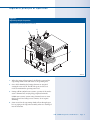
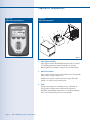
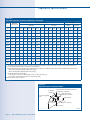
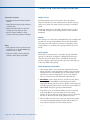
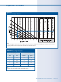
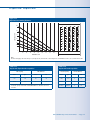
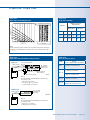
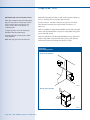
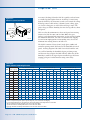
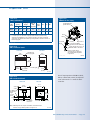
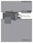
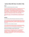
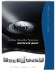
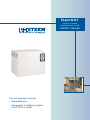
Vapormist
®
E le ctric-to-S te a m
H umidifica tion S y ste m
PR 0 DU C T C ATALOG
®
Now with Vapor-logic 4 controller:
• Web-enabled access
®l
• Interoperability via Modbus or optional
®
®
BACnet MS/TP or LonTalk
Ve r s a t i l i t y f o r f i n i s h e d s p a c e s
The Vapormist humidifier is a compact, cabinet-style unit
compatible with all water types (tap, softened, deionized, reverse
osmosis) and numerous dispersion options. Installation is a
snap — just attach the frame to a supporting structure and connect
electrical and water services.
Available matching Space Distribution Units disperse steam with
no visible vapor trail, making Vapormist ideal for use in finished
spaces.
Comprehensive control with Vapor-logic4
Vapormist with Vapor-logic4 sets new standards for control in
electric steam humidification:
Interoperability allows communication with
building automation systems via Modbus or
with optional BACnet MS/TP or LonTalk
protocols.
DRI-STEEM® offers Space
Distribution Units that match the
Vapormist cabinet. See Page 13.
Safety presets initiate fill and drain cycles
and keep the humidifier cool and safe if
sensed conditions, though unlikely, could be
hazardous.
Web-enabled control allows you to set up, view, and adjust
humidifier functions via Ethernet, either directly or remotely
through a network.
P a g e 2 • D R I - S T E E M Va p o r m i s t h u m i d i f i e r
Va p o r m i s t f e a t u r e s a n d b e n e f i t s
Versatile
• Uses tap, softened, or DI/RO water
• Capacity from 6 to 102 lbs/hr (2.7 to 46 kg/h), link up to 16 units
for capacity up to 1632 lbs/hr (740 kg/h)
• Disperses steam through ductwork with dispersion tubes or
panels, or directly into a room with a Space Distribution Unit
(SDU) mounted remotely or on top of the Vapormist
Flexible
• Control to ±3% RH
• On-off or time-proportioned (TP) control for application control
in most environments; solid-state relay (SSR) option for tight
control
• Electronically monitored water level ensures safe and reliable
operation
Easy to maintain
• Removable cover allows easy access to evaporating chamber and
electrical connections
• Softened water significantly reduces maintenance requirements
• End-of-season autodrain minimizes microbial growth
• User-adjustable water skimmer skims off floating minerals
• Controller-operated drain and flush removes precipitated
minerals from evaporating chamber
• Constant thermal expansion and contraction of heating elements
continuously sheds mineral buildup
D R I - S T E E M Va p o r m i s t h u m i d i f i e r • P a g e 3
Va p o r- l o g i c 4 c o n t r o l l e r
Accurate, responsive control
Keypad/display
Room RH
Mode
The Vapor-logic4 controller provides accurate, responsive RH
control. PID control tunes the system for maximum performance.
Set point
Tank water
level
Softkeys
for direct
menu
access
Steam
output
Tank
status
Navigation
buttons
for item
selection
System
alarms
System
messages
Modbus, BACnet MS/TP, or LonTalk allow interoperability with
multiple building automation systems. Modbus is standard, and
BACnet MS/TP or LonTalk are available options.
Web interface provides the capability to set up, view, and adjust
humidifier functions via Ethernet, either directly or remotely
through a network.
Cycle counter triggers a message when it’s time to replace the
contactor.
USB port allows easy firmware updates, and data backup and
restore capability.
Web interface
Real-time clock allows time-stamped alarm and message tracking,
and accurate drain and flush scheduling.
Auxiliary temperature sensor/transmitter allows air temperature
monitoring, such as in a duct, and enables temperature
compensation to prevent window condensation.
Programmable outputs allow remote signaling and device
activation.
Multiple-humidifier control allows staged control of up to 16
humidifiers with one controller.
Insert a USB flash drive
into the Vapor-logic4
board’s USB port to
perform software
updates, download
data logs, and back
up and restore data.
Controller data, such as RH, air temperature, water use, energy
use, alarms, and messages, can be downloaded to a PC for viewing
and analysis. RH, alarms, and messages can also be viewed on the
keypad/display and Web interface.
Enhanced diagnostics include:
• Test outputs function using keypad/display or Web interface to
verify component operation
• Test humidifier function using simulated demand to validate
performance
mc_042710_1500-VM
P a g e 4 • D R I - S T E E M Va p o r m i s t h u m i d i f i e r
Va p o r m i s t p r i n c i p l e o f o p e r a t i o n
Figure 5-1:
Vapormist principle of operation
Standard water system (shown with cover removed)
4
1
3
2
OM-2000
1.
When the system is first activated, the fill valve opens and the
evaporating chamber fills with water to the operating level.
2.
On a call for humidity, the heating elements are energized,
causing the water to boil. The fill valve opens and closes as
needed to maintain the operating water level.
3.
During refill in standard water systems, a portion of the surface
water is skimmed off, carrying away precipitated minerals.
DI/RO water systems (systems using deionized water or water
that has been treated using reverse osmosis) do not require
skimming.
4.
Steam created in the evaporating chamber flows through vapor
hose or piping to the dispersion assembly, where it is discharged
into the airstream.
D R I - S T E E M Va p o r m i s t h u m i d i f i e r • P a g e 5
Va p o r m i s t c o m p o n e n t s
Figure 6-1:
Vapor-logic4 keypad/display
Figure 6-2:
Vapormist components
5
6
4
7 2
3
1
OM-402-2
1. Vapor-logic4 controller
Vapor-logic4 controls all humidifier functions and can connect
to a building automation system via Modbus or optional
BACnet MS/TP or LonTalk. See Page 4 for more information.
2. Water level control
Tap or softened water systems control water levels electronically
using a three-rod probe (Figure 7-1).
DI/RO water systems control water levels using a float valve
(Figure 7-2) and low-water cutoff switch.
3. Drain
Duration and frequency of draining are user adjustable. To
avoid possible stagnant water and microbial growth, the
humidifier automatically drains if there is no call for humidity
after a user-defined time period (72-hour default).
P a g e 6 • D R I - S T E E M Va p o r m i s t h u m i d i f i e r
Va p o r m i s t c o m p o n e n t s
4. Water skimmer/overflow port
In standard water systems, the water skimmer reduces surface
minerals in the evaporating chamber. Skimming occurs each
time the humidifier fills. The skim time duration is useradjustable.
Figure 7-1:
Water level control for standard-water
humidifier
DI/RO water systems do not require skimming. In DI/RO
systems, the skimmer port functions as an overflow port.
Fill valve closes when water
level rises to this probe.
5. Heating elements
Low-watt-density Incoloy-sheathed heating elements
ensure operation for many seasons. Constant expansion
and contraction of heating elements sheds mineral scale. In
the unlikely event of heater failure, heating elements can be
removed easily.
Fill valve opens when water
level is below this probe.
Low-water cutoff. Power to
heaters is cut if water level
drops below this probe.
6. Removable cover
A removable cover allows easy access to the evaporating
chamber, electrical connections, and drain.
7. Steam outlet
Steam generated in the humidifier rises through the steam
outlet and travels to the dispersion assembly through vapor
hose or piping.
Humidifiers using tap or softened water
control water levels electronically using a
three-rod probe. The controller responds
with the above actions when the water level
reaches each rod.
VLC-OM-030
mc_030910_1335
8. Temperature sensor (not shown)
Mounted on the evaporating chamber, this sensor enables:
• Over-temperature protection
• Freeze protection
• Preheating, allowing rapid response to a call for humidity
Figure 7-2:
Water level control for DI/RO-water
humidifier
Supply water connection
Float ball
Float rod
Humidifiers using DI/RO water control water
levels using a float valve and low-water
cutoff switch.
OM-7396
D R I - S T E E M Va p o r m i s t h u m i d i f i e r • P a g e 7
Va p o r m i s t s p e c i f i c a t i o n s
Table 8-1:
Vapormist capacities, electrical specifications, and weights
Model
Current draw (amps)
Maximum
steam capacity
Weights ‡
Single-phase
Three-phase
Shipping
Operating
kW
lbs/hr
kg/h
120V
208V*
240V*
277V
480V†
600V†
208V*
240V†
277V
480V†
600V†
lbs
kg
lbs
kg
VM-2
6
2.7
16.7
9.6
8.3
7.2
4.2
3.3
—
—
—
—
—
80
36
95
43
VM-4
12
5.4
33.3
19.2
16.7
14.4
8.3
6.7
16.7** 14.4**
12.5
7.2**
5.8**
80
36
95
43
VM-6
18
8.2
—
28.8
25.0
21.7
12.5
10.0
25.0** 21.7**
18.8
10.8**
8.7**
88
40
122
55
VM-8
24
10.9
—
38.5
33.3
28.9
16.7
13.3
33.3** 28.9**
25.0
14.4** 11.5**
88
40
122
55
VM-10
30
13.6
—
—
41.7
36.1**
20.8
16.7
29.1** 25.3**
21.9
12.6** 10.1**
93
42
139
63
VM-12
36
16.3
—
—
—
43.3
25.0
20.0
33.3
28.9
25.0
14.4
11.5
93
42
139
63
VM-14
42
19.1
—
—
—
—
29.2
23.3
38.9
33.7
29.2
16.8
13.5
93
42
139
63
VM-16
48
21.8
—
—
—
—
33.3
26.7
44.4
38.5
33.3
19.2
15.4
93
42
139
63
VM-21
63
28.6
—
—
—
—
43.8
35.0
—
—
43.8
25.3
20.2
95
43
152
69
VM-25
75
34.0
—
—
—
—
—
41.7
—
—
—
30.1
24.1
95
43
152
69
VM-30
90
40.9
—
—
—
—
—
—
—
—
—
36.1
28.9
101
46
156
71
VM-34
102
46.3
—
—
—
—
—
—
—
—
—
40.9
32.7
101
46
156
71
* On 208V/240V/single-phase/three-wire and on 208V/three-phase/four-wire supplies, the neutral line provides a separate 120V circuit for the SDU fan unit.
** For wire sizing, the highest leg draw is shown due to current imbalance.
† Add the following to Vapormist weights if using an SDU option (these weights are for additional control components housed within the Vapormist cabinet):
– SDU-I: 12 lbs (5.5 kg) (SDU-I shipping weight is 68 lbs [31 kg])
– SDU-E: 9 lbs (4 kg) (SDU-E shipping weight is 61 lbs [28 kg])
‡ Add the following if using the SSR option:
– For single-phase or three-phase models drawing less than 21.7 amps, add 2 lbs (1 kg)
– For three-phase models drawing more than 21.7 amps, add 4 lbs (2 kg)
All Vapormist models operate at 50/60 Hz.
mc_042610_0900
Figure 8-1:
Vapormist clearance recommendations
To dispersion
assembly
Top (when SDU is not mounted directly above
the Vapormist): 18"(460 mm)
Right side electrical
controls: 36" (915 mm)
Secured to supporting
wall
Supporting wall
Left side:
12" (305 mm)
Front: 36" (915 mm)
Floor: 24" (610 mm)
mc_042710_1326
P a g e 8 • D R I - S T E E M Va p o r m i s t h u m i d i f i e r
DC-1201
Va p o r m i s t d i m e n s i o n s
Figure 9-1:
Vapormist dimensions
24.2"
(614 mm)
Top view
2" (50 mm)
2" (50 mm)
1" (25 mm)
10.9"
(276 mm)
2.25" (57 mm)
Power wiring knockout
Steam outlet
Control or SDU wiring knockout
Venting
Left side view
Front view
18.6"
(472 mm)
1.50" (38 mm)
2.25" (57 mm)
¾" pipe thread (DN20) frame drain
5.75" (146 mm)
16.1"
(409 mm)
¾" pipe thread (DN20) tank drain
Bottom view
0.50" (13 mm) hole in
base for water fill line
0.75" (19 mm)
0.63"
(16 mm)
2.25" (57 mm)
Power wiring knockout
1.50" (38 mm)
5.75" (146 mm)
24.2"
(614 mm)
mc_042710_1325
Control or SDU wiring knockout
DC-1167
D R I - S T E E M Va p o r m i s t h u m i d i f i e r • P a g e 9
Va p o r m i s t p i p i n g :
Standard water
Figure 10-1:
Vapormist (standard water) field piping overview
Steam vapor hose (maximum run 10' [3 m]). May also use pipe or
tubing. See the DRI-STEEM Design Guide for maximum pipe or tubing
lengths.
Water supply line:
• ¼" NPT (DN8) connection size
• 25 to 80 psi (175 to 550 kPa) required water pressure.
• 100 μS/cm minimum water conductivity.
• If water piping to humidifier is nonmetallic,
the first 3' (1 m) of water supply piping from
humidifier should be metallic.
Unions by installer
2" (50 mm) water seal or loop in supply
line to isolate steam from nonmetallic
supply piping
Install plumb
Shock arrester recommended
to reduce water hammer
¾" pipe thread (DN20)
tank drain, skimmer, and
P-trap piping, rated for
212 °F (100 °C). If piping
run is over 10' (3 m),
increase pipe to 1¼"
(DN32) after P-trap.
12" (300 mm)
2" (50 mm)
1" (25 mm) air gap
Cover
Spill funnel. Plumb
to floor drain.
Frame drain
Open drain required.
See first note below.
¾" pipe thread (DN20) frame drain and
P-trap piping, rated for 212 °F (100 °C)
DC-1136
Notes:
• Locate air gap only in spaces with adequate temperature and air movement to absorb flash steam; otherwise, condensation may form on nearby surfaces.
Refer to governing codes for drain pipe size and maximum discharge water temperature.
• Offset humidifier from spill funnel or floor drain to prevent flash steam from rising into cabinet.
• Dashed lines indicate provided by installer.
• Water supply inlet is more than 1" (25 mm) above skim/overflow port, eliminating the possibility of backflow or siphoning from tank. No additional
backflow prevention is required; however, governing codes prevail.
• Install a union in water supply and drain lines as shown to allow tank removal.
• Damage caused by chloride corrosion is not covered by your DRI-STEEM warranty.
mc_042710_1327-VM
P a g e 1 0 • D R I - S T E E M Va p o r m i s t h u m i d i f i e r
Va p o r m i s t p i p i n g :
DI/RO water
Figure 11-1:
Vapormist (DI/RO water) field piping overview
Steam vapor hose (maximum run 10' [3 m]). May also use pipe or
tubing. See the DRI-STEEM Design Guide for maximum pipe or tubing
lengths.
Water supply line:
• ¼" NPT (DN8) connection size
• 25 to 80 psi (175 to 550 kPa) required water
pressure.
Unions by installer
Strainer, by installer
Install plumb
First 3' (1 m) of water supply line
should be stainless steel tubing
with a 2" (50 mm) water seal or
loop in the supply line to isolate
steam from nonmetallic supply
piping.
¾" pipe thread (DN20) tank
drain, and P-trap piping,
rated for 212 °F (100 °C). If
piping run is over 10' (3 m)
increase pipe to 1¼" (DN32)
after P-trap.
12" (300 mm)
2" (50 mm)
1" (25 mm)
air gap
Frame drain
Spill funnel. Plumb
to floor drain
Open drain required.
See first note below.
¾" pipe thread (DN20) frame drain and
P-trap piping, rated for 212 °F (100 °C)
Cover
DC-1139
Notes:
• Locate air gap only in spaces with adequate temperature and air movement to absorb flash steam; otherwise, condensation may form on nearby surfaces.
Refer to governing codes for drain pipe size and maximum discharge water temperature.
• Offset humidifier from spill funnel or floor drain to prevent flash steam from rising into the cabinet.
• Dashed lines indicate provided by installer.
• The water supply inlet is more than 1" (25 mm) above the overflow port, eliminating the possibility of backflow or siphoning from the tank. No additional
backflow prevention is required; however, governing codes prevail.
• Install a union in the water supply and drain lines as shown to allow tank removal.
• Damage caused by chloride corrosion is not covered by your DRI-STEEM warranty.
mc_042710_1328-VM
D R I - S T E E M Va p o r m i s t h u m i d i f i e r • P a g e 1 1
Drip-free dispersion basics
Guaranteed non-wetting distances
Figure 12-1:
DRI-STEEM dispersion tubes
Using data collected in our on-site test lab, we have developed
guaranteed steam absorption (non-wetting) distances. Performance
charts allow you to confidently choose equipment that will
accommodate any application.
Dry steam
DRI-STEEM’s dispersion tubes are fitted with
one or two rows of closely-spaced thermalresin tubelets to evenly disperse steam across
the airstream.
mc_042610_1555
Figure 12-2:
DRI-STEEM tubelets
Steam
Steam
Steam
Steam
Adding humidification to an airstream without creating wetness
in the duct system is critical for the maintenance of a healthy
environment. Wet areas in ducts are a threat to the health of
building occupants since they moisten dust on duct floors, creating
ideal breeding grounds for disease-producing microbes. In addition,
water accumulating in ducts can drip and cause building damage.
Steam exits drip-free through tubelets
All DRI-STEEM evaporative dispersion tube units discharge steam
through thermal-resin tubelets fitted into dispersion tubes. These
tubelets extend from the center of the tube, where the steam is
driest, through the tube wall, to the duct airstream. In essence,
the tubelets provide a temperature-neutral exit tunnel for steam,
allowing steam to cross over lower-temperature metal without
condensing or dripping. Each tubelet contains a calibrated orifice
sized for steam capacity. These tubelets are a DRI-STEEM exclusive,
and are essential for drip-free steam dispersion.
Air flow
Condensate drains away
Some condensation is inevitable in steam dispersion, but through
careful design, condensate can be controlled and directed away
from where it can cause problems.
Condensate
Steam
Steam
Tubelet
Calibrated
orifice
DRI-STEEM’s unique tubelets extend into the
center of the tube so only the driest steam is
discharged into the air.
mc_042610_1550
OM-150a
For example, the Ultra-sorb dispersion panel has a unique doubleheader design that uses gravity to remove condensate. Steam enters
the supply header, exits through the tubelets, and condensate drains
out the return header. In the Rapid-sorb dispersion unit, steam
enters one end of a single bottom header with velocities carefully
managed so that condensate is not pushed out into the air along
with the steam; it drains out at the opposite end of the header.
Reduce condensate, wasted energy with high-efficiency tubes
To significantly reduce condensate and wasted energy, use
DRI-STEEM’s high-efficiency tubes, which reduce dispersiongenerated condensate and wasted energy by up to 85%. See
“High-efficiency Tube option” on Page 13.
mc_042610_1630
P a g e 1 2 • D R I - S T E E M Va p o r m i s t h u m i d i f i e r
Va p o r m i s t s t e a m d i s p e r s i o n o p t i o n s
Ultra-sorb®
Figure 13-1:
Ultra-sorb dispersion
• Double-header design
• Shortest non-wetting distance; install
within inches of upstream dampers, coils,
or elbows without dripping
• Steam capacity up to 1,850 lbs/hr
(839 kg/h)
• Factory assembled for easy installation
• High-efficiency tube option
OM-636-1
Rapid-sorb®
•
•
•
•
•
Figure 13-2:
Rapid-sorb dispersion
Single-header design
Short non-wetting distance
Steam capacity up to 800 lbs/hr (363 kg/h)
Assembled on-site
High-efficiency tube option
Single or multiple tubes
• Horizontal or vertical airflow
• Available with or without
condensate drain
• Steam capacity up to 85 lbs/hr (39 kg/h)
OM-637-1
High-efficiency Tube option
• Up to 85% reduction in wasted energy,
airstream heat gain, and condensate
production
• PVDF insulation is plenum-approved for
in-duct installation
• Will not absorb water or support microbial
growth; has a closed-cell structure
• Available on Ultra-sorb and Rapid-sorb
mc_042710_1345-NA
Space Distribution Units (SDU)
Figure 13-3:
Single-tube dispersion
Ultra-sorb panel
with high-efficiency tubes
OM-82-1
Figure 13-4:
SDU-E mounted directly above Vapormist
• Designed for use in finished spaces
• Disperse steam into large open spaces;
useful where there are no air ducts
• SDU-E, external absorption, capacities up
to 102 lbs/hr (46.3 kg/h)
• SDU-I, internal absorption, capacities up
to 30 lbs/hr (13.6 kg/h)
OM-55-1
D R I - S T E E M Va p o r m i s t h u m i d i f i e r • P a g e 1 3
Calculating non-wetting distances
Guaranteed absorption
Sample exercise
• Cataloged and guaranteed steam absorption
distances
Read through this exercise to learn more about specifying a
dispersion unit based on non-wetting distance. Assume you have
chosen to use Ultra-sorb units because you want pre-assembled
panels.
• Unique tubelets in dispersion tubes eliminate
condensate drips
• Published absorption tables for sizing and
selecting the correct dispersion option
• Dri-calc® software available for system
selection and absorption distance calculations
Assume the entering air is 20% RH, and the leaving air needs to
be 70% RH. Design for a non-wetting distance of 24" (610 mm)
maximum.
Solution
Notes:
• Final equipment selection should account for
condensate loss. See the DRI-STEEM Design
Guide for steam loss tables.
• Dispersion assembly should accommodate
maximum output capacity of humidifier.
Refer to Figure 15-1. Find 20% entering RH. Proceed vertically until
you intersect the 70% leaving RH line. Draw a line horizontally
from that point to the right to see that for 24" (610 mm) of nonwetting distance, 6" (152 mm) tube spacing would be the closest
match.
Verify capacity
From Table 15-1, note that for 6" (152 mm) spacing, maximum
capacity is 18 lbs/hr/ft2 (88 kg/h/m2). Multiply this value by the
active face area of the Ultra-sorb to determine if the unit will
produce adequate output capacity. If the capacity is inadequate, go
to the next smaller tube spacing.
Steam absorption considerations
1. Non-wetting distance is the dimension downstream from the
leaving side of the steam dispersion assembly to the point where
wetting will not occur, although wisps of steam may be present.
Solid objects at duct air temperature, such as coils, dampers,
fans, etc., downstream of this dimension will remain dry.
2. C A U T I O N ! Non-wetting distances described in this catalog
do not apply when installing a steam dispersion assembly
upstream of filter media. If you need to install a steam dispersion
assembly upstream of filter media, consult your representative or
DRI-STEEM directly for special recommendations.
3. Note that the rise (Δ) in RH (the difference between entering
and leaving RH) has a direct bearing on the non-wetting
distance. As the rise increases, more vapor needs to be dispersed
into the air, and thus the non-wetting distance increases.
4. Uneven airflow over the cross-section of a dispersion assembly
can result in nonuniform mixing of steam with air which, in
turn, will adversely affect the non-wetting distance.
mc_042710_0850
P a g e 1 4 • D R I - S T E E M Va p o r m i s t h u m i d i f i e r
Dispersion: Ultra-sorb
Figure 15-1:
Ultra-sorb non-wetting distances
3"
6"
9"
12"
Note:
The above data apply to all air velocities up to 1,500 fpm (7.6 m/s), and are based on air leaving the zone of humidification at conditions of 55 °F (13 °C) and
the stated % RH. The blue lines in the graph refer to the sample exercise described on Page 14.
mc_042710_0900
Table 15-1:
Ultra-sorb tube spacing and capacity
Tube spacing
Maximum capacity
inches
mm
lbs/hr/ft2
kg/h/m2
3
76
36
175
6
152
18
88
9
229
12
59
12
305
9
44
Note:
The above steam flow capacity data are based on pounds (kg) of steam per hour per square
foot (meter) of face area, exclusive of headers, at various tube spacings.
mc_042710_0905
D R I - S T E E M Va p o r m i s t h u m i d i f i e r • P a g e 1 5
Dispersion: Ultra-sorb
Ultra-sorb LV
Figure 16-1:
Ultra-sorb LV dimensions
• Vertical dispersion tubes
• Suitable for AHUs or ductwork
• Use when duct height is greater than duct
width
A'
G
• May use with pressurized or evaporative
steam (horizontal airflow only)
Supply header
Dispersion tubes
For Ultra-sorb Model LH (horizontal tubes), see the
Ultra-sorb Steam Dispersion Panels Product Catalog
(available at www.dristeem.com).
Table 16-1:
Evaporative steam header capacities
Header capacity
Top view
E
G
Header enclosure
C
Mounting flange
F
B
Header
B'
Header diameter
lbs/hr
kg/h
inches
DN
300
135
3
80
600
270
4
100
1100
500
5
125
1850
820
6
150
Header
Condensate header
H
D
A
Elevation view
E
Side view
OM-123
Table 16-2:
Ultra-sorb LV dimensions
Dimension
Inches (mm)
A Overall width
15" (380) min, 147" (3735) max, in 1" (25) increments
A' Face width
12" (305) min, 144" (3660) max, in 1" (25) increments
B Overall height
21" (530) min, 156" (3960) max, in 1" (25) increments
Panels with overall height more than 98" (2490 mm) are shipped unassembled.
B' Face height
12" (305) min, 144" (3660) max, in 1" (25) increments
C Steam inlet diameter
Determined by maximum steam capacity
D Condensate drain
¾" pipe thread (DN20)
E Header enclosure
(front to back)
For 3" (DN80) and 4" (DN100) headers, E = 5" (127); for 5" (DN125) header, E = 6" (152); for 6" (DN150) header, E = 7" (178)
F Header enclosure
(top to bottom)
For 3" (DN80) header F = 4.5" (114); for 4" (DN100) header, F = 5.5" (140); for 5" (DN125) header, F = 6.5" (165); for 6" (DN150) header F = 7.5" (191)
G Flange
1.5" (38)
H Condensate header
enclosure
4.5" (114)
Note: Header dimensions are determined by capacity. See Table 16-1.
mc_050808_1215
P a g e 1 6 • D R I - S T E E M Va p o r m i s t h u m i d i f i e r
Dispersion: Rapid-sorb
Figure 17-1:
Rapid-sorb non-wetting distances
90
LEAVING % RH
80
70
60
50
40
0
0
10
20
30
40
50
60
70
80
90
6”
ENTERING % RH
9”
12”
18”
24”
DISPERSION TUBE SPACING
Note:
The above data apply to all air velocities up to 1,500 fpm (7.6 m/s) and are based on air leaving the zone of humidification at 55 °F (13 °C) and the stated % RH.
Table 17-1:
Rapid-sorb dispersion tube capacities*
Table 17-2:
Rapid-sorb header capacities
Tube capacity
Tube diameter
Header capacity
Header diameter
lbs/hr
kg/h
inches
DN
lbs/hr
kg/h
inches
DN
d35
d16
1½
40
d250
d113
2
50
36-70
17-32
2
50
251-500
114-227
3
80
501-800
228-363
4
100
* If duct height is <15" (381 mm), tube quantities may need to increase to compensate
for reduced capacity of short tubes. Consult DRI-STEEM or see Dri-calc for the correct
calculation.
mc_042710_1410
D R I - S T E E M Va p o r m i s t h u m i d i f i e r • P a g e 1 7
Dispersion: Rapid-sorb
Figure 18-1:
Rapid-sorb dimensions
A
E
1½" (DN40) dia. dispersion tubes
use slip coupling
B
2" (DN50) dia. dispersion tubes
use hose cuff and clamps
Header outside duct
C
Pitch header toward drain
Escutcheon plate
F
Header inside duct or AHU
D
OM-3005
Note:
Add water seal to condensate drain as shown in the Dri-calc Installation Guides or the humidifier's Installation, Operation and Maintenance manual.
Table 18-1:
Rapid-sorb dimensions
Dimension
Description
Inches (mm)
A
Face width
12" (305) minimum to 120" (3048) maximum in 1" (25) increments
B
Face height
12" (305) minimum to 120" (3048) maximum in 1" (25) increments
C
Steam inlet
Determined by supply steam pressure
D
Condensate drain
¾" pipe thread (DN20)
E
Distance from tube center to inside of duct or AHU wall
4.5" (114) minimum
F
Distance from outside of duct or AHU wall to end of
Rapid-sorb leader
4.5" (114) minimum
Note:
All Rapid-sorb units are custom-sized and field-assembled to fit the duct or air handler. Consult DRI-STEEM for sizes larger or smaller than those listed above.
mc_042710_1415
P a g e 1 8 • D R I - S T E E M Va p o r m i s t h u m i d i f i e r
Dispersion: Single tube
Figure 19-1:
Single tube non-wetting distances
Table 19-1:
Single tube capacities
Maximum capacity of
dispersion tube
NON-WETTING DISTANCE IN INCHES
Tube size
90
Without drain
LEAVING % RH
80
70
With drain
inches
DN
lbs/hr
kg/h
lbs/hr
kg/h
1½
40
28.4
13
56.8
25.8
2
50
56.8
25.8
85.2
38.6
60
50
40
0
0
10
20
30
40
50
60
ENTERING % RH
70
80
90
9”
12”
18”
24”
mc_042710_1416
DUCT HEIGHT
Note:
The above data apply to all air velocities up to 1,500 fpm (7.6 m/s), and are based on air
leaving the zone of humidification at conditions of 55 °F (13 °C) and the stated % RH.
mc_042710_1417
Figure 19-2:
Single tube with and without condensate drain
Table 19-2:
Hose kit sizing by model
Model
With drain
4.5" (114 mm) minimum
from top
Pitch: See Note 1 of duct
Pitch 1/8"/ft (1%)
6"
(152 mm)
4.5" (114 mm)
minimum from
bottom of duct
1½" (DN40) hose kit without drain
1½" (DN40) hose kit with drain
Condensate drain.
Pitch ¼"/ft (2%)
5" (127 mm)
1" (25 mm) air gap
VM 10-16
Without drain
Pitch 2"/ft (15%)
2" (DN50) hose kit without drain
OM-496B
Note 1:
Recommended pitch toward humidifier for interconnecting
hose, tubing, or pipe:
• Vapor hose: 2" per ft (15%)
• 1½" tubing or pipe: ½" per ft (5%)
• 2" tubing or pipe: ¼" per ft (2%)
Pitch: See Note 2
VM 2-8
Hose kit
(vapor hose, dispersion tube, and hardware)
VM 21-25
2" (DN50) hose kit with drain
VM 30-34
These models require multiple tube
assemblies and cannot use a hose kit.
4.5" (114 mm)
minimum from
top of duct
OM-496A
Note 2:
Recommended pitch toward humidifier for interconnecting
hose, tubing, or pipe:
• Vapor hose: 2" per ft (15%)
• Tubing or pipe: 1/8" per ft (1%)
D R I - S T E E M Va p o r m i s t h u m i d i f i e r • P a g e 1 9
Dispersion: SDU
DRI-STEEM's SDUs match the Vapormist cabinet
SDU-I (Space Distribution Unit Internal Absorption)
disperses steam without a visible vapor trail. This
option is ideal for spaces where the presence
of vapor creates either a visual problem or a
condensation risk.
For larger capacities, choose the SDU-E (Space
Distribution Unit External Absorption).
Both SDU models offer extremely quiet, reliable
steam distribution.
Note: SDUs ship separate from the Vapormist.
Mount the Vapormist and SDU to wall studs using the template on
the box. Two lag bolts are provided with each unit.
Provide at least 6" (152 mm) clearance on each side of an SDU
when mounted remotely. For required SDU-E clearances see
Table 22-1.
SDU-I is available for Vapormist humidifier models VM-2 through
VM-8, and all VM-10 models except those using 240V, three-phase
power with SSR control.
SDU-E is available for all Vapormist humidifiers except VM-2 and
models using 240V, 277V, and 480V three-phase power with the
SSR control option and drawing more than 21.7 amps.
Figure 20-1:
SDU mounting options
Remote from Vapormist
OM-56-1
Directly above Vapormist
OM-55-1
P a g e 2 0 • D R I - S T E E M Va p o r m i s t h u m i d i f i e r
Dispersion: SDU
Figure 21-1:
Wall-mounted Vapormist and SDU-I
Keyhole for 3/8" dia.
(M10) fasteners
16"
(406 mm)
SDU
chassis
3" (76 mm)
18.02"
(458 mm)
17.75"
(451 mm)
16"
(406 mm)
0.25"
(6.4 mm)
3" (76 mm)
Keyhole for 3/8" dia.
(M10) fasteners
18.50"
(470 mm)
Vapormist
chassis
24"
(610 mm)
OM-282-4
Figure 21-2:
Wall-mounted Vapormist with SDU-E
Keyhole for 3/8" dia.
(M10) fasteners
16"
(406 mm)
SDU chassis
3" (76 mm)
16"
(406 mm)
18.02"
(458 mm)
16"
(406 mm)
2" (51 mm)
3" (76 mm)
Keyhole for 3/8" dia.
(M10) fasteners
18.5"
(470 mm)
Vapormist
chassis
24"
(610 mm)
OM-282-7
D R I - S T E E M Va p o r m i s t h u m i d i f i e r • P a g e 2 1
Dispersion: SDU
As steam is discharged from the SDU-E, it quickly cools and turns
to a visible fog that is lighter than air. As this fog is carried away
from the SDU-E by the airstream, it tends to rise toward the ceiling.
If this fog contacts solid surfaces (columns, beams, ceiling, pipes,
etc.) before it disappears, it could collect and drip as water. The
greater the space relative humidity, the more the fog will rise, throw
and spread.
Figure 22-1:
SDU-E rise, spread, and throw
Steam outlet
Air intake
grille
Rise
Table 22-1 lists the minimum rise, throw and spread non-wetting
distances for SDU-E at 40%, 50% and 60% RH in the space.
Surfaces cooler than ambient temperature, or objects located within
this minimum dimension, can cause condensation and dripping.
To avoid steam impingement on surrounding areas, observe the
minimum non-wetting distances in Table 22-1.
Throw
Spread
DC-1027
mc_042710_1435
The SDU-E contains a blower (120 V, single-phase, 60 Hz) and
an airflow proving switch (field-wired to the humidifier electrical
panel). A wiring diagram of the SDU-E is included with the unit.
On a call for humidity, the humidifier begins producing steam,
and the start relay energizes the SDU-E blower. When the call for
humidity is satisfied, the Vapor-logic4 controller keeps the blower
running to disperse residual moisture using a time delay.
mc_042710_1255
Table 22-1:
SDU-E minimum nonwetting distances
kW
40% RH @ 70 °F (21 °C)
Maximum
steam capacity
Rise
Spread
50% RH @ 70 °F (21 °C)
Throw
Rise
Spread
60% RH @ 70 °F (21 °C)
Throw
Rise
Spread
Throw
lbs/hr
kg/h
ft
m
ft
m
ft
m
ft
m
ft
m
ft
m
ft
m
ft
m
ft
m
2
6
2.7
1.0
0.3
1.0
0.3
5.0
1.5
1.5
0.5
1.5
0.5
6.5
2.0
2.5
0.8
2.5
0.8
7.5
2.3
4
12
5.4
1.0
0.3
1.0
0.3
5.0
1.5
1.5
0.5
1.5
0.5
6.5
2.0
2.5
0.8
2.5
0.8
7.5
2.3
6
18
8.2
1.0
0.3
1.0
0.3
5.0
1.5
1.5
0.5
1.5
0.5
6.5
2.0
2.5
0.8
2.5
0.8
7.5
2.3
8
24
10.9
1.0
0.3
1.0
0.3
5.5
1.7
1.5
0.5
1.5
0.5
6.5
2.0
2.5
0.8
2.5
0.8
7.5
2.3
10
30
13.6
1.5
0.5
1.5
0.5
6.0
1.8
2.0
0.6
2.0
0.6
7.0
2.1
3.0
1.0
3.0
1.0
8.0
2.5
12
36
16.3
1.5
0.5
1.5
0.5
6.0
1.8
2.0
0.6
2.0
0.6
7.0
2.1
3.0
1.0
3.0
1.0
8.0
2.5
14
42
19.1
2.0
0.6
2.0
0.6
7.0
2.1
2.0
0.6
2.0
0.6
7.0
2.1
3.0
1.0
3.0
1.0
9.0
2.7
16
48
21.8
2.0
0.6
2.0
0.6
7.0
2.1
2.0
0.6
2.0
0.6
7.0
2.1
3.0
1.0
3.0
1.0
9.0
2.7
21
63
28.6
2.0
0.6
2.0
0.6
7.5
2.3
2.5
0.8
2.5
0.8
10.0
3.0
3.0
1.0
3.0
1.0
12.0
3.7
25
75
34.0
2.0
0.6
2.0
0.6
8.0
2.5
2.5
0.8
2.5
0.8
10.5
3.2
3.5
1.1
3.5
1.1
12.5
3.8
30
90
40.9
2.0
0.6
2.0
0.6
8.0
2.5
2.5
0.8
2.5
0.8
10.5
3.2
3.5
1.1
3.5
1.1
12.5
3.8
34
102
46.3
2.0
0.6
2.0
0.6
8.0
2.5
2.5
0.8
2.5
0.8
10.5
3.2
3.5
1.1
3.5
1.1
12.5
3.8
Notes:
• Surfaces or objects directly in the path of vapor discharge may cause condensation and dripping.
• To avoid steam impingement on surrounding areas, observe the minimum nonwetting dimensions in this table.
• Rise: The minimum nonwetting height above the steam outlet of the SDU-E.
• Spread: The minimum nonwetting width from the steam outlet of the SDU-E.
• Throw: The minimum nonwetting horizontal distance from the steam outlet of the SDU-E.
mc_042710_1300
P a g e 2 2 • D R I - S T E E M Va p o r m i s t h u m i d i f i e r
Dispersion: SDU
Table 23-1:
SDU specifications**
Maximum
capacity
Figure 23-4:
SDU-E drain line piping
Shipping
weight
lbs/hr
kg/h
lbs
kg
Amps at
120V
(50/60 Hz)
SDU-E
102
46.3
61
28
2.07
1/8
545
0.26
64
SDU-I
30
13.6
68
31
3.20
1/5
760
0.36
58
SDU
model
Horsepower
cfm
m3/s
dB*
* Measurement taken 6.5' (2 m) in front of SDU cabinet.
** For visible vapor to be absorbed completely within the SDU-I unit before being
discharged as humidified air, room air must be 45% RH or less. Trying to maintain
greater than 45% RH will cause visible vapor and potential for moisture collection on
the discharge grille.
Install SDU-E frame
plumb and level
Union
Elbow
Drain
1" (25 mm)
air gap
mc_042710_1440
Figure 23-2:
SDU-I mechanical detail
Front view
Humidified air
discharge grille
Dispersion box
¾" pipe thread (DN20)
dispersion box drain and P-trap
piping, rated for 212 °F (100 °C)
Spill funnel. Plumb to floor drain.
Open floor drain. Refer to
governing codes for drain pipe
size and maximum temperature
requirements.
Side view
24.2"
(615 mm)
4" (102 mm)
16.1"
(409 mm)
mc_042710_1445
OM-1245
18.6"
(472 mm)
10.9"
(276 mm)
1½" (DN40)
steam inlet
Air intake grille
2.25"
(57 mm)
DC-1076
Note: If using Vapormist models VM-10, VM-12,
VM-14, or VM-16 with an SDU-E, the Vapormist
steam outlet must be 2" to match the SDU-E
steam inlet.
Figure 23-3:
SDU-E mechanical detail
Front view
Steam
outlet
Side view
16.1"
(409 mm)
24.2"
(615 mm)
¾" (DN20) pipe
thread drain
nipple.
See note
below.
18.6"
(472 mm)
3.2" (82 mm)
10.9"
(276 mm)
1½" (DN40)
or 2" (DN50)
steam inlet
Steam inlet
Note: SDU-E dispersion box requires an installed condensate drain line
and water seal, provided by installer. See Figure 23-4.
2.25"
(57 mm)
DC-1078
D R I - S T E E M Va p o r m i s t h u m i d i f i e r • P a g e 2 3
Conserving resources
through better performance
Expect quality from the industry leader
For more than 45 years, DRI-STEEM has been
leading the industry with creative and reliable
humidification solutions. Our focus on quality
is evident in the construction of the Vapormist
humidifier, which features cleanable, stainless
steel construction. DRI-STEEM also leads the
industry with a Two-year Limited Warranty and
optional extended warranty.
For more information
www.dristeem.com
[email protected]
For the most recent production information
visit our web site:
www.dristeem.com
DRI-STEEM Corporation
An ISO 9001:2000 certified company
U.S. Headquarters:
14949 Technology Drive
Eden Prairie, MN 55344
800-328-4447 or 952-949-2415
952-229-3200 (fax)
European office:
Marc Briers
Grote Hellekensstraat 54 b
B-3520 Zonhoven
Belgium
+3211823595 (voice)
+3211817948 (fax)
E-mail: [email protected]
Continuous product improvement is a policy of
DRI-STEEM Corporation; therefore, product features and
specifications are subject to change without notice.
DRI-STEEM, Dri-calc, Rapid-sorb, Ultra-sorb,
Vapor-logic, and Vapormist are registered trademarks of
DRI-STEEM Corporation and
are filed for trademark registration in
Canada and the European community.
Area-type and Drane-kooler are trademarks of
DRI-STEEM Corporation.
Product and corporate names used in this document may
be trademarks or registered trademarks. They are used
for explanation only without intent to infringe.
Ultra-sorb is covered by the following Patents, with
additional patents pending: United States Patent numbers
5,126,080; 5,277,849; 5,372,753; 5,376,312; 5,543,090
© 2010 DRI-STEEM Corporation
Form No. VM-CAT-0510
DRI-STEEM conserves resources by designing humidification
systems that optimize performance. Systems that perform well save
energy and water and, ultimately, cost less to operate and maintain.
Save energy
For applications requiring short absorption, highefficiency dispersion tubes reduce wasted energy
up to 85% by significantly reducing
airstream heat gain and condensate
production. Available for new and
retrofit Ultra-sorb® and Rapid-sorb®
steam dispersion panels.
For warm, dry applications, DRI-STEEM’s
High-Pressure Atomizing System disperses
unheated micro-fine water particles into
airstreams or open spaces. As atomized water
droplets evaporate, air temperature drops,
reducing the cooling load. This provides
significant energy savings when humidifying
and cooling simultaneously.
Save water
Ultra-sorb Model XV eliminates water waste
and reduces airstream heat gain, energy
costs, and boiler chemical use. Available for
all pressurized steam applications.
Optimize performance
DRI-STEEM’s most advanced controller,
Vapor-logic®4 continuously monitors space
conditions to align humidifier output with
demand. The result is accurate, responsive
control.
Your DRI-STEEM representative is:
mc_022310_1415