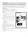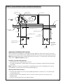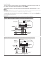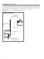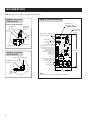
1
Humidifier
Steam Humidifier
Models 1150 and 1160
Installation, Operation, and Maintenance Manual
READ AND SAVE THESE INSTRUCTIONS
TABLE OF CONTENTS
PRODUCT OVERVIEW . . . . . . . . . . . . . . . . . . . . . . . . . . . . . . 3
Materials Provided and Not Provided . . . . . . . . . . . . . . . . . . 3
Electrical Specifications, Capacities and Weights . . . . . . . . 4
OPERATION
Start-up Procedure . . . . . . . . . . . . . . . . . . . . . . . . . . . . . . . . 27
MAINTENANCE
Dimensions. . . . . . . . . . . . . . . . . . . . . . . . . . . . . . . . . . . . . . . 5
Inspect and Service the Humidifier . . . . . . . . . . . . . . . . . . . 29
Overview of Humidifier Operation . . . . . . . . . . . . . . . . . . . . . 7
Off-season Shut Down Procedure . . . . . . . . . . . . . . . . . . . . 31
INSTALLATION
TROUBLESHOOTING . . . . . . . . . . . . . . . . . . . . . . . . . . . . . . 32
Wiring Diagrams . . . . . . . . . . . . . . . . . . . . . . . . . . . . . . . . . . 9
REPLACEMENT PARTS . . . . . . . . . . . . . . . . . . . . . . . . . . . . 36
Setting Slide Switches. . . . . . . . . . . . . . . . . . . . . . . . . . . . . 11
Choosing a Location for Humidifier Components . . . . . . . . 13
APPENDIX – ABSORPTION
DISTANCE CALCULATION. . . . . . . . . . . . . . . . . . . . . . . . . . 38
Distribution Tube Installation . . . . . . . . . . . . . . . . . . . . . . . 15
WARRANTY . . . . . . . . . . . . . . . . . . . . . . . . . . . . . . . Back Cover
Mounting the Humidifier . . . . . . . . . . . . . . . . . . . . . . . . . . . 18
Field Wiring . . . . . . . . . . . . . . . . . . . . . . . . . . . . . . . . . . . . . 19
Airflow Proving Switch Installation . . . . . . . . . . . . . . . . . . . 23
Supply Water and Drain Piping . . . . . . . . . . . . . . . . . . . . . . 23
ATTENTION INSTALLER
This product must be installed by qualified HVAC and
electrical contractors. Failure to do so voids product
warranty due to possible product misapplication.
This product must be installed in compliance with
local, state, and federal codes.
CAUTION
1. Do not set humidity higher than recommended.
Condensation damage may result.
2. Failure to follow the instructions in this manual
for installation of distribution tube, airflow
proving switch, and high humidity limit switch
may cause condensation damage.
WARNING
1. 240 volts may cause serious injury or death from electrical
shock. Disconnect power before installing supply wiring.
2. Water temperature in excess of 140°F (60°C) may cause
serious injury due to burns. Allow unit to cool before
draining or removing chamber.
3. The humidifier chamber, distribution assembly, and all
connected hose or piping may contain or discharge hot
steam and/or hot water at 212°F (100°C). Discharged
steam is not visible. Contact with hot surfaces,
discharged hot water, or air into which steam has been
discharged may cause severe personal injury.
4. Water pressure greater than 80 psi (550 kPa) may cause
the humidifier to overflow.
5. Humidifier weighs up to 80 lbs when operating.
Improper mounting of humidifier may cause humidifier
to fall from wall or ceiling resulting in serious injury.
Mount humidifier to a structurally stable surface per the
instructions in this manual.
6. Failure to properly ground unit may result in property
damage due to fire, or serious injury or death from
electrical shock.
7. Failure to follow the instructions in this manual may
cause moisture to accumulate, which may cause
bacteria and mold growth or dripping water into building
spaces. Dripping water may cause property damage.
2
PRODUCT OVERVIEW
Aprilaire Steam Humidifiers create steam by boiling water inside a steam chamber. This is accomplished by the transfer of energy
from electric heating elements to the water inside the chamber. A three-level water probe is used to determine when to turn on
and off a water fill valve in order to bring water into the chamber. Once the chamber is full and there is a call for humidity from
the Automatic Steam Humidifier Control, the heating elements will be energized causing the water to boil. The boiling water
creates steam which, due to the moderate pressurization of the chamber that comes from boiling, is forced through the vapor
hose and steam distribution tube into the duct system. As water is boiled off, the water level in the steam chamber will drop. The
water probe will sense when it reaches a low point and will cause the fill valve to open.
The process of boiling the water in the steam chamber will cause minerals and impurities in the water to drop out. Depending
on the hardness and quality of the water, this can create a substantial build-up within the steam chamber. The unit will drain the
chamber periodically to help clean the steam chamber and reduce the amount of cleaning required during maintenance.
Aprilaire Steam Humidifiers are controlled by an Automatic Steam Humidifier Control mounted in the return duct that will sense
the relative humidity (RH) in the return air. If the return air is below the RH setpoint, the control will send the humidifier a signal
to begin producing steam. Once this happens, the airflow proving switch (included) will check to ensure that the equipment
blower is operating. If the blower is not operating, the humidifier will send the equipment a signal to turn the fan on.
• The Aprilaire Steam Humidifier Model 1150, 12 lb/hr unit, features an Automatic Steam Humidifier Control with on/off control.
The on/off control will send a 10 VDC signal to the humidifier when the measured return air RH is 3% or more below setpoint
to turn the unit on at 100% output.
• The Aprilaire Steam Humidifier Model 1160, 24 lb/hr unit, features an Automatic Steam Humidifier Control with modulating
control. This control sends a signal between 0 and 10 VDC that is proportional to the difference between setpoint RH and
the measured return air RH. The signal for 100% humidifier output is 10 VDC and occurs at a control point that is adjustable.
The signal for 50% output is 5 VDC and occurs at the setpoint. The adjustable RH proportional control band can be set on the
board to 6%, 9%, 12% (default), or 15%. The humidifier uses this varying signal to time-proportion the operation of the heating
elements in the chamber.
The Automatic Steam Humidifier Control features an outdoor temperature sensor and is equipped to provide RH setpoint
compensation based on the actual outdoor temperature. When the weather gets colder outside, there can be problems with
condensation when introducing humidity into the building. The control recognizes this and adjusts the setpoint in the building to
a lower level. The control will still provide humidity to the building, but will not attempt to maintain a humidity level higher than
is appropriate for the current outdoor temperature. For applications that require specific set-point control, regardless of outdoor
temperature, the Control can be set up for manual operation. In Manual Mode, the outdoor temperature sensor is not used and
the RH is controlled to the specific setting on the Control.
MATERIALS PROVIDED
1
1
1
1
2
2
2
2
1
1
1
Humidifier (Model 1150: 1 heater, 12 lbs/hr; Model 1160: 2 heater, 24 lbs/hr)
Distribution Tube (Model 1150: 10” active, 14” overall; Model 1160: 16” active, 20” overall)
10 ft. Steam Hose, 1 ½” I.D.
1 ft. Drain Hose, 1” I.D.
Hose Clamps (for Steam Hose), 1 ½” I.D.
Hose Clamps (for Drain Hose), 1” I.D.
Face Plates for Mounting Distribution Tube (1 set)
3/8” x 2” Lag Bolts for Mounting Humidifier
Automatic Steam Humidifier Control
Airflow Proving Switch
Installation, Operation, and Maintenance Manual
MATERIALS NOT PROVIDED
Electrical Supplies – quick disconnect box,
conduit, and wire (for power to the unit
and wiring to control devices)
Plumbing Supplies – supply and drain
piping, fittings, etc.
High Humidity Limit Switch
Hanging Brackets
(for mounting humidifier from ceiling)
3
FIGURE 1 – Product Overview
Distribution Tube
1½” (DN40) flexible steam hose
Duct
Control wiring knockout
Power wiring knockout
Electrical controls area
Internal controller board
Field wiring terminal block
Electrical power area
Display panel
Immersion heaters
(1 in Model 1150, 2 in Model 1160)
Fill Valve
1/4” (DN8)
compression
fitting
¾” (DN20) copper
overflow and drain
Removable steam chamber
Cover/shroud
OM-4006
TABLE 1 – Electrical Specifications
Model
number
Maximum
steam capacity
Current draw
(amps)
Single-phase
Circuit
Breaker
(amps)
minimum
kW
lbs/hr
kg/h
240V*
1150
12
5.4
16.7
25
1160
24
10.9
33.3
45
Shipping weight
(includes packaging and
all materials in the box)
Operating weight
(humidifier only, with
water in chamber)
lbs
kg
lbs
kg
4
70
32
67
30
8
70
32
74
34
Note: Models 1150 and 1160 operate at 50/60 Hz.
* 208V single-phase may also be used but the steam capacity will be approximately 25% lower than the values above. It is recommended that the same size
circuit breakers be used with 208V single-phase as listed above for 240V.
4
FIGURE 2 – Dimensions (pertains to Models 1150 and 1160)
Power wire knockout
TOP VIEW
11.89”
(302 mm)
6.50”
(165 mm)
5.50”
(140 mm)
3.09”
(78 mm)
1.00” (25 mm)
Control wire knockout
Steam outlet
24.06”
(611 mm)
LEFT SIDE
VIEW
Venting
FRONT VIEW
18.93”
(481 mm)
9.99”
(254 mm)
BOTTOM VIEW
24.06”
(611 mm)
Chamber drain
Chamber fill
0.83” (21 mm)
1.37” (35 mm)
3.06” (78 mm)
1.19” (30 mm)
OM-4018
5
FIGURE 3 – Mounting Hole Locations
�����
��������
���������
�����
����������������
���������������������
�������������
90-914
FIGURE 4 – Distribution Tube Dimensions
����������
���������������
����������
����������������
���������������������������
������������������������������
��������������
������������������
����������������������������
����������
���������������
����������
����������������
���������������������������
������������������������������
����������������������������
��������������
����������������
90-912, 90-913
6
OVERVIEW OF HUMIDIFIER OPERATION
INTERNAL CONTROLLER
The internal controller within the humidifier cabinet responds to external inputs (e.g., humidistat and airflow proving switch) and
internal inputs (e.g., water level probe inside the steam chamber) to provide:
• Relative humidity (RH) control
– Model 1150: With an on-off demand signal, the controller
maintains RH within 5% to 7% of set point.
– Model 1160: With a modulating demand signal, the
humidifier maintains RH within 2% to 4% of set point.
Modulating demand signal options include a 0–10 VDC
humidistat signal (humidistat provided), or a signal by
others (0–10 VDC or 4–20 mA).
• Automatic water level control and safety shut-down
If there is insufficient water, an electronic water level
probe sends a signal to the controller to add water or to
turn off the heaters.
• Operating time monitoring
The controller accumulates humidifier run time to activate
end-of-season draining, water cool-down, and auto draining.
• Automatic preheating
During chamber refilling, once there is enough water in
the chamber, the heaters energizes at 100% until the
water approaches boiling temperature to preheat the
chamber water so it is warm when the humidifier receives
a humidity demand signal.
• Automatic end-of-season draining
If the humidifier doesn’t receive a humidity demand signal
for 72 hours, the chamber automatically drains.
• Periodic drain and flush
To reduce mineral buildup in the chamber, the humidifier
automatically drains at intervals based on operating time,
output capacity, and water type. At the end of the drain
cycle, the supply water is brought on to briefly flush the
chamber.
• Chamber water cooling before draining
To ensure that water is at or below 140°F (60°C) before
discharging to the plumbing system, the humidifier remains
idle for a defined period of time before draining.
• Ensuring duct airflow
The humidifier will not make steam unless the HVAC
system blower is on and the airflow proving switch verifies
there is airflow in the duct.
DISPLAY PANEL AND INDICATOR LIGHTS
The display panel shows operating status and troubleshooting information. See the display panel detail (Figure 5) and the table
describing display panel lights (Table 2). For more information about blinking indicator lights, see the troubleshooting section in
this manual.
FIGURE 5 – Display Panel
On/Off
switch
Steam
Fill
Drain
On/Off
Indicator
light
OM-2028-M
7
TABLE 2 – Display Panel Light Indications
Indicator light(s)
Status
Description
All
Blinking sequentially from
right to left
The humidifier is in a forced cool-down period prior to a required automatic drain sequence.
Normal operation
On
Power is on. Normal operation.
Slow blinking (1/sec.)
The electronic water level probe needs cleaning.
Fast blinking (10/sec.)
Probe logic fault. See Troubleshooting section.
On
The humidifier is draining. Normal operation.
Blinking
The allowed amount of time for draining has been exceeded. Fault in drain operation.
Humidifier will continue to operate. See Troubleshooting section.
On
The humidifier is filling. Normal operation.
Blinking
The allowed amount of time for filling has been exceeded. Fault in fill operation.
Humidifier will not operate. See Troubleshooting section.
On
The humidifier is making steam. Normal operation.
Blinking
The humidifier has received a demand signal but cannot make steam because:
• There is not enough water in the chamber, or
• An enable/safety switch is open, or
On/Off (switch)
Drain
Fill
Steam
Note:
See the Troubleshooting section in this manual for more information.
AUTODRAIN SEQUENCE MINIMIZES OUTPUT INTERRUPTIONS
The humidifier drains and flushes automatically at regular intervals to remove minerals from the chamber.
After the humidifier has run for a preprogrammed amount of time, and if there is no demand for humidity, the humidifier sits idle
until the chamber cools and then it drains.
If the humidifier has not completed an autodrain sequence due to continual demand signal interruptions, after an additional
amount of run time the humidifier begins a cool-down period and then it drains.
IMPORTANT: The humidifier attempts to complete an autodrain sequence when there is no demand for humidity. However,
if an autodrain sequence is not completed within a defined period of time, the humidifier ignores the demand signal until
completing an autodrain sequence. This could cause the relative humidity level in the humidified space to drop until the autodrain
sequence completes.
8
INSTALLATION
FIGURE 6 – Model 1150 Wiring Diagram
APRILAIRE STEAM HUMIDIFIER MODEL 1150
SINGLE HEATER WIRING DIAGRAM
ON/OFF CONFIGURATION
������������
�����������������
��
��
���������
������
�����
�����
��
���
��
��
��
������
�����
����
��
��
��
�
��
�
��
��
�
���
��
��
�
��
�������
���
��������
���������
������������
������
�
�
�
�
�
�
�
�
��
��
�
����������������������
���������������
�
��
�
�
������������
���������������
������
��
��
���
�
����������������
����
���
�����
��
�
���������������
�����������
������
������
��������
������
�����������
����
�����
��
�������������������
����������������
��
������
��
�
���
�
�
�� ��
�
��
�
�
�����������������������������
������������������������������
��������������������
�
��
��
��
���
���
���
�
�����������������������
�
������������������������
��
��
��
���
���
���
��
������������
��
�
��������������
��
�
���
���
���
�
�
�
���
���������������������
�����������������
� � �
��
���������������������������������������
���
��
���������
���������
��
��
��
� ���������
���
���
�
��
� ���������
��
��
���
��
��
�
��
��
��
��
��
��
��
��
��
�����
���
������
���
������
���
���������������
������������������
��
���
���
������
�����������������
�������������������
��
��
��
�����������������������������
���
� ����������
��
��
���������������������
����
���
������������
�
��
�
��������������������������
�� �
�
������������������������
�� ���
�� ���
�
������
���
���
���
���
�
�
�
���
���
��
��
��
���
���
���
�
���������������
������������������������������
AA-LW420-1
9
FIGURE 7 – Model 1160 Wiring Diagram
APRILAIRE STEAM HUMIDIFIER MODEL 1160
DUAL HEATER WIRING DIAGRAM
MODULATING CONFIGURATION
������������
�����������������
��
��
���������
������
�����
�����
��
������
�����
����
��
��
�
���
��
�
���
��
�
���
��
���
��
���
��
��
��
��
�
�
������������
���������������
���������������
������
�
�
�
�
�
�
�
���������������
���������������
����������������������
���������������
�
��
�
���������������
������
��
��
�
������������
�������
���
��������
���������
��
��
���
�
����������������
����
���
�����
��
�
���������������
�����������
������
������
��������
������
�����������
�����
��
�
�������������������
����������������
��
������
��
���
�
�
�� ��
�
��
�
�
�����������������������������
������������������������������
��������������������
�
��
��
��
���
���
���
�
�����������������������
�
������������������������
��
��
��
���
���
���
��
������������
��
��
�
��������������
�
���
���
���
�
�
�
���
���������������������
�����������������
� � �
��
�������������������������������������������
��
���
���������
���������
��
� ����������
��
��
� ���������
�
��
� ���������
��
��
�����������������������������
���
��
���
���
���
��
�����������������
�������������������
��
��
�
���������������
������������������
��
��
���
��
������������
�
������
��
��
��
��
��
��
��
��
��
��
���������������������
����
�����
���
������
���
������
���
���
�
��
���
���
���
��
��
�
��������������������
�� ���
�
������
�
�
�
���
���
��
��
��
���
���
���
�
���������������
������������������������������
AA-LW420-2
10
SETTING SLIDE SWITCHES
IMPORTANT: Slide switch on-off positions 1 through 16 are preset at the factory. These settings are determined
by output capacity, water type, and demand signal type. Changing these settings will affect humidifier operation.
Change on-off positions only per the instructions in this manual or as instructed by Aprilaire technical support staff.
On the internal controller inside the humidifier, there are two banks of slide switches. Most are set at the factory according to
the model type. Others, however, must be set according to the details of each particular installation. See Figure 8. Note: the ‘Off’
slide switch position is to the left while the ‘On’ slide switch position is to the right. For wiring details see page 21.
Type of Control Input
Model 1150 with an on/off control: S1 slide switch positions 1 and 2 Off
Model 1160 with modulating control: S1 slide switch positions 1 and 2 Off
Model 1160 with 0-10 VDC signal by others: S1 slide switch positions 1 and 2 Off
Model 1160 with 4-20 mA signal by others: S1 slide switch positions 1 and 2 On
Inlet water type
The controller allows autodrain settings for three water supply types:
FIGURE 8 – Slide Switches
• Normal water (hardness greater than 4 and less than
10 grains/gallon)
LED lamp
Mounting hole
• Hard water (hardness greater than or equal to 10 grains/gallon)
• Softened water (hardness less than or equal to 4 grains/gallon)
S1
Position
The humidifier is preprogrammed for use with normal water. If your
water supply is hard or softened, follow the instructions below:
• For hard water supply (greater than or equal to 10 grains/gallon
of hardness):
– Set switch S1 position 3 to On; position 4 remains Off.
See Figure 8.
S2
• For softened water supply:
– Set switch S1 position 4 to On; position 3 remains Off.
See Figure 8.
Substituting a remote fault alarm for blower starting
The humidifier may be field programmed to send a fault alarm signal
to a remote device instead of sending a signal to start the HVAC
equipment blower.
Internal Controller Board
Note:
Slide switches are shown in the off position.
OM-2038
To enable this function, set slide switch S2 position 9 to On and
provide wiring to control terminals NO, O, and NC. See Figure 8
for slide switch positions.
If you change any on-off settings, record them in Table 3
for future reference.
11
TABLE 3 – Factory Slide Switch Settings
Slide switch S1
Position
Factory setting
1
Slide switch S2
My setting
Position
Factory setting
Off
9
Off
2
Off
10
See Table 4
Do not change.
3
Off
11
Off
Do not change.
4
Off
12
Off
Do not change.
5
See Table 4
Do not change.
13
Off
Do not change.
6
Off
Do not change.
14
Off
Do not change.
7
Off
Do not change.
15
Off
Do not change.
8
Off
Do not change.
16
Off
Do not change.
Note: Positions 5-8 and 10–16 are for factory use only.
TABLE 4 – Slide Switch S1 Settings by Model
Model
12
Position
5
10
1150
Off
On
1160
On
Off
My setting
CHOOSING A LOCATION FOR HUMIDIFIER COMPONENTS
Before proceeding with the installation, you must first determine where the steam distribution tube will be installed as well as
the humidifier itself.
Steam Distribution Tube and Controls Location
Since this dictates the rest of the installation, first determine where the steam distribution tube will be mounted in the ductwork
of the HVAC system. Refer to Figure 10 for split system installations and Figure 11 for rooftop unit installations. These figures
also indicate where control devices are to be installed.
Absorption Distance
Absorption distance is the amount of open space in the duct downstream of the distribution tube required for steam to be
absorbed into the air. If the duct contains obstructions such as dampers or elbows within the absorption distance, condensation
on those obstructions can occur. Factors affecting absorption distance include RH of air upstream of the distribution tube, air
temperature inside the duct, air velocity in the duct, and amount of moisture required. In most Model 1150 and 1160 applications,
the clear space required for absorption distance is less than 36”. In fact, in many applications the absorption distance may be
as short as 6”. If the duct has obstructions within 36” of the distribution tube, actual absorption distance can be calculated. In
applications with a large difference between the RH upstream and downstream of the distribution tube, an absorption distance
greater than 36” may be required. To calculate actual absorption distance, follow the procedure listed in the Appendix.
Humidifier Location
When selecting the location of the humidifier, consider the following:
• Proximity to duct
To avoid having to install a drain at the distribution tube in the duct, the distribution tube must be mounted at an elevation
higher than the humidifier. A 10’ (3 m) length of vapor hose is provided with the unit. The hose can be cut if less than 10’ (3 m) is
needed. The hose must have a constant downward slope from the distribution tube to the humidifier of at least 2”/ft (15%). If the
distribution tube must be installed at an elevation lower than the humidifier, install a drip tee and drain as shown in Figure 23.
• Required clearances (see Figure 9)
• Electrical connections
Electrical power supply, water supply piping, and drain piping must also
be considered. Electrical power supply connections are made at the upper
left rear corner of the unit. The control wiring is in the upper right rear
corner. Another consideration when choosing a location for the humidifier
is to avoid areas close to sources of electromagnetic emissions such as
power distribution transformers.
• Plumbing connections
Water supply piping connections are made in the lower right rear corner.
Drain piping connections are made at the lower left rear corner.
FIGURE 9 – Recommended Minimum
Service and Maintenance Clearances
To distribution tube
Secured to
supporting
wall
Top:
18” (460 mm)
Right side: 12”
(305 mm)
Supporting
wall
Left side:
12” (305 mm)
Front: 36”
(915 mm)
Floor: 24” (610 mm)
OM-4011
13
DISTRIBUTION TUBE AND CONTROL DEVICES LOCATION OPTIONS
FIGURE 10 – Recommended Installation Locations, Split System Application
���������������������������
�������������������������
����������������������������
�������������������������
���������������
������������
������������
������
������
��
���
���� �
������
�������������������
������
������������
������������
������������
������
�������
����������������
�����������������
������������������
CHOOSING A DISTRIBUTION TUBE LOCATION
When installing a steam humidifier on a split system, there are three locations that can be used to mount the steam
distribution tube: the supply plenum (Location A), the return duct (Location B), or a supply branch (Location C).
Note: Wherever distribution tube is installed, there must be a minimum of 4.5” between top of tube and the duct
ceiling. Refer to Figures 12 and 13 on page 17.
Location A is the best choice because:
• The distribution tube is humidifying 100% of the air, and
• The supply air temperature is typically warmer than the return air temperature, allowing for better absorption.
Location B is the second choice because the distribution tube is humidifying 100% of the air, but the cooler
temperature of the return air requires more space for absorption.
Location C should be the last choice because, in most cases, there is more than one branch off the supply air
plenum, and less than 100% of the air would be humidified in such a multi-branch system. However, if there is only
one branch, the Location C would be considered equal to Location A because the same reasons listed under
Location A would apply.
Choosing control device locations
• Install the high humidity limit switch (a recommended optional device) a minimum of 5’ (1.5 m) downstream
of the distribution tube.
• Install the Automatic Steam Humidifier Control in the return air drop a minimum of 6” upstream of the distribution tube.
• Install the airflow proving switch in the supply air plenum.
OM-4016
14
FIGURE 11 – Placing a Distribution Assembly in a Rooftop Air Handler Application
������������
����������
��������������
�������
������������
�������
���
����
��������������������������
���������������������������
�������������
�������
�������������������
����������
�������������������
����������
�������
��������������
����������
���������������
������������������
��������������
������������
�����������������
���������
�����������
�����������
CHOOSING A DISTRIBUTION TUBE LOCATION
When installing a steam humidifier on a packaged rooftop unit application, there are two locations that can be
used to mount the steam distribution tube: supply plenum/duct (Location A) or the return plenum/duct (Location B).
Note: Wherever distribution tube is installed, there must be a minimum of 4.5” between top of tube and the duct
ceiling. Refer to Figures 12 and 13 on page 17.
Location A is the best choice because:
• The distribution tube is humidifying 100% of the air
• The supply air temperature is typically higher than the return air temperature, allowing for better absorption
of the steam
Note: In applications using zone control products, the distribution tube must be installed upstream of all zone
control dampers to ensure that all zones receive humidified supply air
Choosing control device locations
• Install the high humidity limit switch (a recommended optional device) a minimum of 5’ (1.5 m) downstream
of the distribution tube.
• Install the Automatic Steam Humidifier Control in the return air duct a minimum of 6” upstream of the
distribution tube.
• Install the airflow proving switch in the supply air plenum.
OM-4043
15
DISTRIBUTION TUBE INSTALLATION
After the location for the distribution tube has been identified, follow the steps below and refer to Figure 12 to install the
distribution tube in the duct.
1. Cut or drill a 1 5/8” diameter opening in the duct.
2. Drill a 3/8” hole in the opposite surface of the duct so that the distribution tube has a 2”/ft. (15%) pitch, sloping back towards
the humidifier. The distribution tube is to be positioned in the duct such that 1 1/2” – 3 1/2” of the tube is extending out of the
duct for attachment of the steam hose.
3. Use a 3/8”-16 mounting bolt (included) to secure the end of the tube to the far side of the duct.
4. If the duct is wider than the distribution tube, attach a 3/8”-16 threaded rod cut to the appropriate length (not provided) to the
end of the tube. Secure end of threaded rod with 3/8”-16 nut and washer. See Figure 13.
5. Orient distribution tube so that tubelets (steam orifices) point up. To help verify this, on the section of tube that will be sticking
outside of the duct, mark a spot that is line with the tubelets.
6. If the distribution tube is shorter than the duct width causing the steam tubelets to be outside the duct, plug the exposed
tubelet openings with silicon caulk.
7. Attach each of the two halves of the face plate to the duct using sheet metal screws, fitting the face plates tightly against the
distribution tube.
8. Seal any gaps around face plates using silicon caulk.
CAUTION
The hose must have a minimum pitch of 2”/ft. (15%) from the distribution tube back to the humidifier. If not possible due to
obstructions or duct configuration, a drip tee and drain must be installed. See Figure 23 on page 26. Failure to follow these
recommendations can result in excessive back pressures on the humidifier. This may lead to distribution tube spitting,
steam blowing through the P-trap before the plumbing system, or leaking gasket.
WARNING
Distribution tube, steam hose, tubing or hard pipe may contain steam, and surfaces may be hot. Discharged steam is not
visible. Contact with hot surfaces or air into which steam has been discharged may cause severe personal injury.
16
FIGURE 12 – Distribution Tube Installation
Duct
Steam hose; do not exceed
10’ (3 m) in length
Distribution tube
Hose pitch: 2”/ft (15%)
4.5” minimum from
tube to duct ceiling
Mounting nut
3/8” - 16
Mounting bolt
3/8” - 16 x 1/2”
Humidifier
Tube pitch: 2”/ft (15%)
Secure and seal
face plates
OM-4008
FIGURE 13
Distribution tube
4.5” minimum from tube
to duct ceiling
3/8” - 16 Threaded rod
Face Plates
90-915
17
MOUNTING THE HUMIDIFIER
Mounting the humidifier on the wall
When mounting on a wood stud wall (studs 16” [406 mm] on center), locate studs and position lag bolts in place so that each of
the bolts centers on a stud. Mark hole locations and predrill ¼” (6 mm) diameter pilot holes. Secure cabinet to wall with lag bolts
provided.
When mounting on a metal stud wall, locate the studs (16” [406 mm] on center) and drill a 3/8” (10 mm) hole through the studs
and wall. Push a 3/8” (10 mm) bolt through the wall, studs, and a backing plate on the backside of the wall and secure with a nut
and washer.
If 16” (406 mm) on-center studs are not available, mount spanner boards on the wall, spanning two studs. If two horizontal boards
are used, locate one at the top of the cabinet for the lag bolts and the other board located 3” (76 mm) on center from the bottom
of the cabinet.
For hollow block or poured concrete wall mounting, mark holes 16” apart. Drill appropriate pilot holes for two 3/8” (10 mm) toggle
bolts or two 3/8” (10 mm) machine bolt lead anchors. Secure cabinet in place.
When suspending the unit from ceiling or roof structural members
Required Parts:
2 Brackets, P/N 4593
4 Bolts, 1/4 - 20, 3/4 long , plated.
4 Nylon insert nuts, 1/4 - 20
8 Flat Washers, 1/4 -20, plated (thin washers)
8 Washers, 1/4 -20, plated
4 Threaded Rods, 3/8 - 16 (length depends on installation specifics. Not provided.)
Procedure:
1. Remove the shroud covering of the humidifier.
2. Insert the first bolt through the side slot farthest to the rear of the humidifier. Follow the “Fastener Sequence” listed below,
ensuring the bolt head is on the inside of the humidifier frame.
3. Repeat the “Fastener Sequence” for the humidifiers vertical side slot located toward the front.
NOTE: The metal of the frame will need to be flexed in order to insert the left front bolt.
4. Repeat steps 2 & 3 for the other side.
5. Use four lengths of 3/8 inch threaded rod to suspend the humidifier. Observe all applicable codes and standards.
Fastener Sequence:
Starting from the inside of the humidifier:
Bolt, flat washer, through the vertical slots on the side of the humidifier frame, 1/4-20 washer, 1/4-20 washer, Bracket
(use the small holes the same side as the slots), flat washer, Nylon insert nut.
INSTALL STEAM HOSE
Attach one end of the steam hose to the distribution tube and the other end to the humidifier. Secure with 1 1/2” hose clamps
at both ends. Ensure that a minimum pitch of 2”/ft. (15%) is maintained along length of hose. If pitch is not possible, it will be
necessary to install a tee fitting and p-trap. Refer to Figure 23 on page 26 for details. If the 10’ hose is not long enough to reach
from the humidifier to the distribution tube, use 1-1/2” copper tubing.
18
FIELD WIRING
Humidifier field wiring
All wiring must be in accordance with all governing codes and with the humidifier wiring diagram. Wiring diagrams are on pages
9 and 10 in this manual and the wiring diagram for your humidifier model is located inside the removable shroud. Power supply
wiring must be rated for 221°F (105°C). The maximum ambient temperature is 80°F (27°C).
Field wiring connections and requirements
• Conduit knockouts are provided on the top of the cabinet. Control wiring knockouts are on the back right; power wiring
knockouts are on the back left.
• Control wiring and power wiring must be run in dedicated or separate earthed metal conduit, cable trays, or trunking.
• Separate the line voltage wiring from low voltage control circuit wiring when routing electrical wiring inside the
humidifier cabinet.
• Do not use chassis or safety grounds as current-carrying commons. Never use a safety ground as a conductor or neutral to
return circuit current.
CAUTION
Adding alternate conduit connections should not be necessary; however, when making holes and knockouts in the
humidifier cabinet, protect all internal components from debris and vacuum out cabinet when finished. Failure to comply
with this warning can damage sensitive electronic components and void the Aprilaire warranty.
Below are field wiring connections:
• Connect to line power.
Refer to the wiring diagram or the dataplate on the outside of the cabinet for wire sizing amperage.
• Connect to control signal wiring.
(from the Automatic Steam Humidifier Control or from signal by others). Mount the Automatic Steam Humidifier Control in the
return air duct as shown in the drawing on pages 14 and 15. See page 21 for wiring details. Also, refer to the Installation and
Operating Manual for the Automatic Steam Humidifier Control.
• Connect to the HVAC system blower.
To start the HVAC equipment blower when the humidifier receives a humidity demand signal, wire the NO, O, and NC control
terminals to the HVAC system as shown on the wiring diagram.
• Connect to a remote fault alarm (optional).
The humidifier may be field programed to send a fault alarm signal to a remote device instead of sending a signal to start the
HVAC system blower. To enable this function, set slide switch S2 position 9 to On and provide wiring to control terminals NO,
O, and NC.
• Connect to the duct airflow proving switch wiring.
The airflow proving switch is a safety device that will prevent the humidifier from producing steam when there is no airflow
present in the HVAC system. See page 23 for details.
• Connect to the duct high humidity limit switch wiring.
(a recommended optional device). Locate the duct high humidity limit switch the correct distance downstream of the
distribution tube. See Figure 10 on page 14 and Figure 11 on page 15 for more location guidelines.
IMPORTANT: Installation of a duct high humidity limit switch is highly recommended.
19
WARNING
240 volts may cause serious injury or death from electrical shock. Shut off power at main breaker before
installing supply wiring for humidifier.
WARNING
Failure to properly ground unit may result in property damage due to fire, or serious injury or death from
electrical shock.
LINE POWER
The humidifier is designed for 240 VAC, single phase, 50/60 Hz input
power. The Model 1150 requires a 25 amp (minimum) breaker while
the Model 1160 requires a 45 amp (minimum) breaker. Install a fused
quick disconnect box nearby the humidifier for easy access during
maintenance of humidifier. See Figure 14.
FIGURE 14 – Line Power Wiring Requirements
Power
supply
208 VAC single-phase, 50/60 Hz input power may also be used.
Note that when using 208 VAC the steam capacity of each unit will
be reduced by approximately 25% compared to rated capacity at
240 VAC.
Fused
disconnect
Line power grounding requirements
The ground connection must be made with solid metal to metal
connections. The ground must be a good radio frequency earth.
Ground wire should be the same size as power wiring.
�����
����
�����
������
OM-4007
CONTROL WIRING
Proper control wiring prevents electrical noise.
Electrical noise can produce undesirable effects on electronic
control circuits, which affects controllability. Electrical noise
is generated by electrical equipment such as inductive
loads, electric motors, solenoid coils, welding machinery, or
fluorescent light circuits. The electrical noise or interference
generated from these sources (and the effect on controllers)
is difficult to define, but the most common symptoms are
erratic control or intermittent operational problems.
FIGURE 15 – Shielded Cable Wire Connection to C Terminal
C terminal
IMPORTANT
• For maximum electromagnetic compatibility effectiveness,
wire all humidity, high limit, and airflow controls using
multicolored shielded plenum-rated cable with a ground
wire for the shield. Connect the ground wire to the
C terminal on the field wiring terminal block in the
humidifier. See Figure 15. Use wire less than 2” (50 mm)
in length for the shielded cable ground wire.
• Do not ground shield at the device end.
OM-4015
20
Control input wiring
The internal controller offers four input control types, which are field adjustable. The factory default control type for Model 1150
is the Automatic Steam Humidifier Control, on-off configuration as shown in Figure 16.
The factory default control type for Model 1160 is the Automatic Steam Humidifier Control, modulating configuration as shown in
Figure 17.
IMPORTANT: For Model 1150 on/off control, verify that the shunt on the JP2 jumper is placed over the 2 & 3 position. For Model
1160 modulating control, verify that the shunt on the JP2 jumper is placed over the 1 & 2 position.
To change the input control type on Model 1160 to signal by others, see Figure 18 for a 0-10 VDC signal, and see Figure 19 for a
4-20 mA signal (input resistance 250 ohms).
IMPORTANT: Note the internal controller slide switch S1 settings in each control input wiring diagram.
FIGURE 16 – Model 1150: Input Wiring for Automatic Steam Humidifier Control (on/off configuration)
� � �
����������
��������������������������
��������������������������
����������������
���
��������������������
�����������������������
���������������������
����������������������������
������������������������
����������
������������������
���������
����������������
�������
�������������
������������
��
��
���
�
��
��
���
���������������
��������������
���������������
��������������
�������
��������������
�
��
�
������ ������
������
�
�
����������������
������������
��������������
�
������
������
��������������
90-916
FIGURE 17 – Model 1160: Input Wiring for Automatic Steam Humidifier Control (modulating configuration)
����������
��������������������������
��������������������������
����������������
� � �
���
��������������������
�����������������������
���������������������
����������������������������
����������������������������
����������
������������������
���������
����������������
�������
�������������
������������
��
��
���
�
��
��
���
���������������
��������������
���������������
��������������
�������
��������������
�
�
������ ������
��
������
�
������
�
�
������
����������������
������������
��������������
��������������
90-917
21
FIGURE 18 – Model 1160: Input Wiring for Optional 0-10 VDC Signal by Others
����������
���������������������������������������
�����������������������������
����������������
��������
�
�
�������������
������������
���������������
��������������
���������������
��������������
�������
��������������
�
�
��
������
������ ������
�
�
�
������
������
����������������
������������
��������������
��������������
90-918
FIGURE 19 – Model 1160: Input Wiring for Optional 4-20 mA Signal by Others
����������
���������������������������������������
����������������������������
�
����������������
�������
���������������������������
�
�������������
������������
���������������
��������������
���������������
��������������
�������
��������������
�
�
������ ������
��
������
�
������
�
�
������
����������������
������������
��������������
��������������
90-919
22
AIRFLOW PROVING SWITCH INSTALLATION INSTRUCTIONS
Description:
The airflow proving switch is a safety device that will prevent
the humidifier from producing steam when there is no airflow
present in the HVAC system. The switch is a pressure differential
measuring device that determines if there is airflow present
based on the pressure differential between the HVAC system and
atmosphere. The switch contains a diaphragm, calibration spring,
and a snap acting SPDT switch. See Figure 20 for details.
FIGURE 20
Diaphragm
Terminal
Enclosure
Mounting
Bracket
Operation:
When the HVAC equipment fan is off, the airflow proving
switch is open. In the event of a demand “call” from the
humidistat in this state, the airflow proving switch would prevent
the humidifier from starting or producing steam.
Inlet H: High
Inlet L: Low
When the airflow proving switch senses that the HVAC
equipment fan is on, the switch closes. This position will allow
the humidifier to come on and produce steam.
Installation:
Do not mount in this
manner. Diaphragm
must be mounted in
a vertical plane
The airflow proving switch is mounted on any surface free from
vibration. The airflow proving switch must be installed with the
diaphragm in a vertical plane. (See Figure 20 for acceptable and
unacceptable mounting configurations.) Avoid mounting the switch with the inlet line connections facing up.
90-889
The air sampling probe (included) must be located a minimum of 1.5 duct diameters downstream from the discharge of the HVAC
equipment blower. It is connected to the airflow proving switch by a 1/4” field supplied plastic tubing. The hose is connected to
inlet H on the switch housing, while inlet L remains open to the atmosphere. (See Figure 20)
Using the ‘Normally Open’ and ‘Common’ terminals inside the terminal enclosure, wire the airflow proving switch to the field
wiring terminal block in the humidifier according to the wiring diagram on page 21 depending on the humidifier model number.
See Figures 16-19 on page 21.
The airflow proving switch is field adjustable from .05” w.c. to 12” w.c.. To adjust the set point, turn the adjusting screw counter
clockwise (CCW), until motion has stopped. Next, turn the adjusting screw 4 complete turns in a clockwise direction to engage the
spring. From this point, the next 10 turns will be used for calibration. The optimum setting is one that will only close the switch
when the fan is in operation. Each full turn of the adjustment screw represents approximately 1.2” w.c.
To properly calibrate an airflow proving switch, a digital manometer or other pressure measuring device should be used to confirm
the actual set point.
SUPPLY WATER AND DRAIN PIPING
The humidifier is designed to operate with hot or cold, hard or soft water. Be sure to set slide switches on the internal controller
board to guidelines on page 11. Supply water piping may be of any code-approved material (copper, steel, or plastic). The fill
valve connection size is a ¼” (DN8) compression fitting. In cases where water hammer may be a possibility, consider installing a
shock arrestor. Water pressure must be between 25 psi and 80 psi (175 kPa and 550 kPa).
Drain piping may be of any code-approved material (copper, steel, or plastic rated for 140°F [60°C] minimum). If drainage by
gravity is not possible, use a reservoir pump rated for 140°F (60°C) water.
23
The final connection size is 1” (DN25) hose or ¾” (DN20) copper for the chamber drain. Do not reduce this connection size.
(See Figures 21 and 22 for proper drain piping configurations.)
A 12” (305 mm) piece of 1” (DN25) hose is provided to function as the flexible connection from the drain valve to the field
installed drain plumbing. The flexible connection provides a disconnect point so that the chamber can be removed for cleaning.
(See Figure 21).
Hard piping can be connected directly to the drain valve, but the vertical drop should be minimized prior to a horizontal run. Install
a union at the beginning of the horizontal run to remove the chamber for cleaning. (See Figure 22).
If the equivalent length of pipe from the humidifier drain to the plumbing system drain is more than 10’ (3 m), increase the pipe
size to 1¼” (DN32). See Figures 21 and 22.
FIGURE 21 – Field Piping Overview Showing Hose Drain Connection
Steam hose
(maximum run 10’ [3 m])
Water supply line
Shock arrester
recommended to
reduce water hammer
¾” (DN20) copper
chamber drain and
overflow piping,
rated for 140°F
(60°C). If piping run
is over 10’ (3 m)
increase pipe
to 1¼” (DN32).
1” (25 mm)
air gap
Spill funnel;
plumb to
floor drain
¼” (DN8) compression
fitting on fill valve
connection to water
supply line; water
pressure must be between
25 psi and 80 psi
(175 kPa and 550 kPa);
water conductivity
minimum 100 µS/cm2;
fill valve has an integral
strainer
Install plumb
1” (25 mm) flexible drain
hose and clamps
Open drain required. Locate air gap only in
spaces with adequate temperature and air
movement to absorb flash steam; otherwise,
condensing on nearby surfaces may occur.
Refer to governing codes for drain pipe size
and maximum discharge water temperature.
Notes:
• Dashed lines indicate provided by installer.
• The water supply inlet is more than 1” (25 mm) above the skim/overflow port, eliminating the possibility of backflow or siphoning from the chamber.
No additional backflow prevention is required; however, governing codes prevail.
OM-4017
24
FIGURE 22 – Field Piping Overview Showing Hard Pipe Drain Connections
Steam hose
(maximum run 10’ [3 m])
Water supply line
Shock arrester
recommended to
reduce water hammer
Union by installer
¼” (DN8) compression
fitting on fill valve
connection to water
supply line; water
pressure must be between
25 psi and 80 psi
(175 kPa and 550 kPa);
water conductivity
minimum 100 µS/cm2;
fill valve has an integral
strainer
Install plumb
¾” (DN20) copper
chamber drain
and overflow
piping, rated for
140°F (60°C).
If piping run
is over 10’ (3 m)
increase pipe to
1¼” (DN32).
1” (25 mm)
air gap
Spill funnel;
plumb to
floor drain
Open drain required. Locate air gap only in
spaces with adequate temperature and air
movement to absorb flash steam; otherwise,
condensing on nearby surfaces may occur.
Refer to governing codes for drain pipe size
and maximum discharge water temperature.
Notes:
• Dashed lines indicate provided by installer.
• The water supply inlet is more than 1” (25 mm) above the skim/overflow port, eliminating the possibility of backflow or siphoning from the chamber.
No additional backflow prevention is required; however, governing codes prevail.
OM-4010
25
DISTRIBUTION DRIP TEE INSTALLATION
If the humidifier cannot be mounted below the steam distribution tube, such that there is a minimum 2”/ft (15%) pitch along the
entire hose length, a drip tee as shown below must be installed. Failure to follow the recommendations on this page, when the
humidifier is mounted higher than the distribution tube, can result in excessive back pressures on the humidifier. This may lead to
distribution tube spitting, steam blowing through the P-trap before the plumbing system, or leaking gasket.
IMPORTANT: Steam hose must be supported to prevent sagging or low spots.
FIGURE 23 – Drip Tee Installation
Steam hose
or hard pipe
�����
Insulate tubing and
hard pipe to reduce
steam loss
����
�����
������
Humidifier
Dashed lines indicate
provided by installer.
To distribution
tube
6” (150 mm) recommended
8” (200 mm)
minimum
1” (25 mm)
air gap
Copper tubing or pipe drip tee,
by installer
¾” (DN20)
Funnel or floor drain.
Refer to governing codes for
drain pipe size and maximum
temperature requirements.
OM-4009
26
OPERATION
HUMIDIFIER START-UP PROCEDURE
WARNING
240 volts may cause serious injury or death from electrical shock. Do not remove the power/ heater
terminal cover until electrical power is disconnected. Only qualified electrical personnel should perform start-up procedure.
After the system is properly installed and connected to both electrical and water supplies, it can be started.
START-UP PROCEDURE:
Mounting
Before filling with water, check mounting to verify that the steam chamber is level and securely supported. Refer to Maintenance
Section, page 29, for details on securing the steam chamber.
Piping
Verify that all piping connections are completed as recommended and that water pressure is available.
Use cold or hot supply water. If the water pressure is above 60 psi (415 kPa) and/or water hammer is excessive, install a
pressure-reducing valve or shock arrester. Even though the humidifier has an internal 1” (25 mm) air gap, some governing codes
may require backflow prevention.
IMPORTANT: Minimum water supply pressure is 25 psi (175 kPa).
TABLE 5 – Torque Specifications
Electrical
Before start-up, verify that electrical connections have been made per
governing codes and the wiring requirements listed in this manual.
• Verify that all power terminal screws and lugs are tight from power block to
heaters. See Table 5 for torque specifications.
• Verify that the transformer, drain valve, fill valve, and contactor electrical
plugs located under the humidifier shroud are completely plugged in.
Torque
Screw or lug location
inch-lbs
Nm
Power block
16
1.8
Contactor or Relay
16
1.8
8-32 nut
(8.5 mm)
20
2.2
10-32 nut
(9.5 mm)
25
2.8
6 gauge wire
(10 mm2)
35
4.0
8 gauge wire
(6 mm2)
25
2.8
10-14 gauge wire
(<6 mm2)
20
2.2
Heater
nut
• Confirm the internal controller board slide switch S1 and S2 positions
marked 1 through 16 are in the correct on or off position.
Heater
wire lug
27
Water Supply
• Turn water supply on; confirm drain valve is closed.
Power
• Turn the supply power on.
– Verify that the On/Off indicator light illuminates along with the Fill indicator light.
– Verify that the fill valve opens and adds water until the humidifier chamber is full, at which time the fill valve closes and the
Fill indicator light turns off.
– Verify that there are no leaks from the humidifier.
FIGURE 24 – Probe Rod Assembly
Create Water Seal
Probe
plug
• Unplug the probe plug from the probe assembly (located on the chamber cover;
see Figure 24) to allow the fill valve to energize and overfill the chamber. This
ensures that the water seal (P-trap) is filled with water. When water is seen
coming from the drain line, plug the probe plug back into the probe assembly.
Probe
assembly
Initiate Fan Call
• Set up a fan call at the thermostat. If the humidifier is configured to bring on
the equipment fan with a humidity demand, skip to next step.
Probe housing
OM-4052
Initiate Humidity Demand
• For the default Model 1150 and 1160 controls, whether in Automatic or Manual Mode, rotate control knob of the Automatic
Steam Humidifier Control clockwise to the ‘Test’ position.
– Verify that the steam indicator light illuminates and energizes the heaters. In the ‘Test’ position, the humidity demand will
last for 1 minute only.
WARNING
In the event the humidifier chamber does not contain water and the heaters are energized, turn main power
off. Operation of the heaters without water may cause humidifier malfunction and/or fire, resulting in property damage,
personal injury or death.
NOTE: Do not leave the Automatic Steam Humidifier Control in the ‘Test’ position. Refer to the Installation and Operation Manual
for the Automatic Steam Humidifier Control for more details.
28
MAINTENANCE
The best way to determine how often the humidifier needs maintenance is to remove the steam chamber and inspect it after the first
year of operation. Potable water carries a variety of minerals and other materials in a mix that varies from location to location. This
variation in water quality, combined with the hours of operation and duty cycle, determines the frequency maintenance required.
TO INSPECT AND SERVICE HUMIDIFIER:
1. Access and prepare the steam chamber (Item 6) for removal
(see Figure 25 for drawing item numbers):
FIGURE 25 – Chamber with
Closed Fastener
10
CAUTION
If the drain light is blinking on the display panel (Item 1 in drawing),
there is water in the chamber that was unable to drain. Model 1160 chambers
weigh 40 pounds (18 kg) when full of water; Model 1150 chambers weigh 30
pounds (13.4 kg) when full of water. Take the necessary precautions to
support the additional weight when removing the chamber fasteners.
3
7
Chamber cover
1
8
6
11
A. Loosen the fasteners on the top of the shroud.
2
9
5
4
B. Remove the fasteners on the bottom of the shroud.
OM-4019
C. Remove the shroud.
WARNING WARNING: 240 volts may cause serious injury or death from electrical shock. Do not remove the
power/heater terminal cover (Item 10) while the electrical power is on.
D. If the steam chamber is cool to the touch, skip to Step 1E. If the chamber is hot, the water must be cooled down before
draining and handling of the chamber. This can be accomplished by allowing sufficient time for the chamber to become cool
enough to handle. As an alternative, if the drain piping is designed to handle intermittent drain water temperatures up to
212°F (100°C), the chamber may be cooled down by moving the lever located on the drain valve actuator to the manual open
position. The fill valve eventually opens, allowing water to run into the chamber until it is cool enough to handle.
IMPORTANT: If water is not draining from the chamber after Step 1D, the drain valve is likely clogged and the chamber
must be cooled by introducing overfill water into the chamber. To do this, unplug the probe plug from the probe assembly
(located on the chamber cover) to allow the fill valve to energize and overfill the chamber. When the chamber is cool enough
to handle, plug the probe plug back into the probe assembly. Take necessary precautions to support the additional
water weight when removing the steam chamber fasteners.
WARNING Opening the drain valve when the steam chamber is hot may discharge water with a temperature up to 212°F
(100°C) into the plumbing system. This may cause damage to the plumbing system. Do not touch the chamber or drain piping
until the chamber has had sufficient time to cool or serious injury may result.
E. Shut off the water supply.
F. Shut off the electrical supply.
G. Allow the steam chamber to completely drain.
H. Disconnect the drain hose or field-installed union from the drain valve connection on the back left corner of the cabinet.
Disconnect the drain valve electrical plug.
29
2. Remove the steam chamber (see Figure 25 for drawing item numbers):
• Hold up on the bottom of the steam chamber (Item 6 in drawing) and remove
the top mounting nuts (Items 2 and 3).
FIGURE 26 – Probe Rod Assembly
Probe
plug
• Hold up on the bottom of the steam chamber while removing the bottom
mounting nut (Item 4). When the bottom mounting nut is removed, the
handle (Item 5) falls away from the steam chamber. Use both hands to
support the steam chamber and lower it straight down to clear heaters. Use
care not to damage gasket which is attached to the top lip of the chamber.
Probe
assembly
3. Clean the steam chamber interior by rinsing with clean water. Use a putty knife
or similar flat instrument to remove mineral deposits. Clean the strainer inside
the steam chamber located over the steam chamber drain opening. Use a wire
brush and verify that all the strainer holes are open.
Probe housing
OM-4052
4. Open the drain valve with the manual lever on the side of the actuator (Item 11) and run water through the drain valve to
remove any collected sediment.
5. Unscrew the probe assembly and clean the plastic probe housing, ensuring that all passageways are clear (see Figure 26).
Clean the probe rods using steel wool or a similar mild abrasive material. Inspect the composite plastic probe assembly for any
signs of cracking, roughness, or deterioration. Replace if necessary with Part Number 4580.
6. Install the probe assembly, probe plug, probe housing and the gasket into the cover (see Figure 26).
7. Re-install the chamber (see Figure 27 for drawing item numbers):
• Using both hands, lift the chamber (Item 6 in drawing) up around the heaters
until the threaded fasteners penetrate the cover flange.
FIGURE 27 – Chamber with
Open Fastener
• Hold the chamber in place with one hand and pull the handle (Item 5)
toward you and up onto the threaded fastener on the front bottom of the
chamber. Make sure gasket is centered on chamber flange.
3
2
1
Chamber cover
• Push the handle up against the backing nut (Item 9) and run nut (Item 4)
up the threaded fastener so it holds the handle in place.
6
• Tighten nut (Items 2 and 3) down on the threaded fasteners extending
through the cover flange.
• Tighten nuts (Items 2, 3, and 4) to complete the process of returning
the chamber to its position prior to removal.
• Reconnect the drain hose to the drain valve connection in the back
left corner.
9
5
4
• Reconnect the drain valve electrical plug.
8. Verify electrical connections:
• Verify that all power terminal screws and lugs are tight from power block to heaters.
• Verify that all electrical plugs located under the shroud are completely plugged in (transformer, contactor, drain valve,
and fill valve).
9. Move the drain valve lever back to the auto position.
10. Turn on the water supply.
30
OM-4020
11. Turn on the electrical power.
12. Allow the steam chamber to fill with water and initiate a humidity demand
signal (see Figure 28 for drawing item numbers).
FIGURE 28 – Steam Chamber
with Closed Fastener
• IMPORTANT: Verify that the gasket seal is not leaking prior to
leaving the humidifier unattended.
2
– If a leak is observed in the left front or side of the gasket, loosen
backing nut (Item 7 in drawing) one turn and tighten fastener nut
(Item 2) down onto the cover flange. Continue this one turn at a time
until the leak stops.
3
7
Chamber cover
– If a leak is observed in the right front or side of the gasket, loosen backing
nut (Item 8) one turn and tighten fastener nut (Item 3) down onto the cover
flange. Continue this one turn at a time until the leak stops.
1
8
6
9
5
4
OM-4019
– If a leak is observed in the rear of the steam chamber, loosen backing nut (Item 9) two turns and tighten up fastener nut
(Item 4) onto the handle. Continue this two turns at a time until the leak stops. Replace gasket if necessary.
13. If this maintenance occurred at the end of a humidification season, turn the demand for humidity down to the minimum
setting and the humidifier will go into an end-of-season drain after 72 hours.
14. If this maintenance occurred during the humidification season, turn the demand for humidity to the desired set point.
OFF-SEASON SHUT DOWN PROCEDURE
Perform steam chamber cleaning and humidifier maintenance at the end of the humidification season.
• If softened water is used, the steam chamber may not need cleaning until after several humidification seasons.
• IMPORTANT: The steam chamber should be removed after the first season of use to observe the amount of
collected minerals in the chamber.
• If there is more than ½” (13 mm) of minerals in the steam chamber after one season of use, clean the chamber annually.
• If it is determined that cleaning is necessary every two or three seasons, then the only off-season shut-down procedure
required is to turn the demand for humidity down to the minimum setting.
• The steam chamber will go into an end-of-season drain after 72 hours without a demand for humidity.
• When humidification is desired, turn the demand up to the desired set point and the system will start up.
31
TROUBLESHOOTING
Problem
Possible Cause
Action
All indicator lights are
blinking sequentially
from right to left
The humidifier is in a forced • This is normal operation. DO NOT RESET POWER. The humidifier will automatically resume
cool-down period prior to
making steam once it has cooled down, drained, and refilled.
a required automatic drain
sequence.
All indicator
lights are off
On/Off switch is off
• Push On/Off switch on display panel.
Display panel ribbon cable
connection
• Connect display panel ribbon cable.
• Verify ribbon cable is connected correctly. See Figures 29 and 30.
Transformer secondary
circuit breaker tripped
• Check for wiring shorts; reset breaker.
Power panel breakers are
open
• Check power block for proper voltage present at transformer.
• Verify transformer electrical plug is fully engaged.
The enable/safety circuit is
not satisfied.
• If no other lights are on or blinking, check the airflow proving switch:
– Verify that tube orientation in the duct is correct.
– Verify tube is connected to the switch correctly.
– If connections are correct and switch does not close with airflow, replace switch.
• Check high humidity limit switch (if installed):
– Verify connection per the wiring diagram and the diagram on the high humidity limit switch cover.
– Verify that the high humidity limit switch is the correct distance downstream of distribution tube.
– If connections and location are correct, replace high humidity limit switch.
Low water condition
• If the fill light is also on:
– Verify that the water shut-off valve is open.
– Check fill valve strainer; clean or replace if clogged.
• If the fill light is also blinking, refer to the “Fill light on the display panel is blinking on and off”
section below.
• Verify that lever on drain valve actuator is in ‘Auto’ position.
When in a fill sequence, the
internal controller allows
15 minutes for water to
reach the maximum upper
water level. If water is not
sensed at the top probe of
the probe assembly after
filling for 15 minutes, the
fill light on the display
panel will blink on and off.
Chamber is not full
• Verify that lever on drain valve actuator is in ‘Auto’ position.
• Verify that water shut-off valve is open.
• Verify that the fill valve electrical plug is fully engaged.
• Verify proper fill valve wiring at terminals 33 and C.
• Verify voltage supplied to fill valve is correct. Valve coil should be 24 VAC.
• Check fill valve strainer; clean or replace if clogged. Check the strainer by disconnecting the fill
valve inlet fitting. Remove the strainer with a small screwdriver.
• Fill valve may be plumbed backward. Note flow direction and correct as needed.
• Verify that water supply pressure is at least 25 psi (175 kPa).
• Verify that fill and drain valve wiring are not reversed.
• Remove fill valve and check for any foreign material plugging the valve.
• Excessive water hammer can bend a needle valve on the supply line and make it difficult to open.
If this is happening, the valve may need to be replaced. Install a water hammer shock arrestor.
Chamber is full
• Clean or replace probe.
• Check water conductivity. Water conductivity must be at least 100 µS/cm2. Add salt to increase.
Steam light on the
display panel is
blinking on and off
Fill light on the display
panel is blinking on
and off (fill fault)
Unit will not operate
There are two causes for
this: either the chamber
did not fill, or the chamber
filled but water is not
being detected.
Drain light on the
display panel is
blinking on and off
(drain fault)
Unit will continue
to operate
32
When in autodrain sequence
or end-of-season drain, the
internal controller allows 14
minutes for the water level
to drop from the top probe
to below the lowest probe.
If the chamber does not
drain to this level in the time
allotted, the drain light on
the display panel will blink
on and off.
• Verify that drain valve electrical plug is fully engaged.
• Check drain valve wiring at terminals 32 and C.
• Check for voltage present at the valve. Input power to the drain valve actuator should be
24 VAC; if present, clean or replace valve.
• Check if the chamber drain outlet from the humidifier is plugged. Clean if needed.
Water detection probes
• Clean probes or replace probe rod assembly.
Fill valve
• Fill valve may be plumbed backwards. Note flow direction on valve body and replumb if necessary.
• If fill valve is plumbed correctly and leaking water, replace fill valve.
Drain line is backing up
with water
• Verify drain line pitch. Pitch drain pipe toward drain 1/8”/ft (1%) minimum.
• Verify drain line size. If piping run is over 10’ (3 m) , increase drain pipe size from ¾” (DN20) to
1¼” (DN32).
• Verify that the drain line is not plugged. Disconnect drain piping from the humidifier at the hose
or union connection. Replace or clean drain piping if there is standing water in the piping or if
water does not flow freely through the drain piping.
Problem
Possible Cause
Action
The On/Off light on
the display panel is
blinking slowly (one
blink per second)
Mineral buildup or
oxidation on probe rods
• Remove probe assembly and clean probe rods; reset power to clear warning.
Deterioration of probe rod
assembly
• Replace probe rod assembly.
The On/Off light on
the display panel is
blinking rapidly (10
blinks per second)
(illogical probe fault)
Probe is wired incorrectly
• Verify wiring; see wiring diagram.
• Verify that probe wires are routed separately from high voltage wires to avoid interference.
• Verify the green and yellow ground wire is connected to the subpanel and to the C terminal.
Deterioration of probe rod
assembly
• Replace probe rod assembly.
Chamber water is foaming.
• Clean chamber.
No remote fault
indication (drain fault,
fill fault, illogical
probe fault)
Field wiring not installed
• Provide field wiring to a remote fault indicator from NO, O, NC control terminal block.
Remote fault relay is not
switching.
• Check relay continuity NO, O, NC control terminal block for contact closure.
Note: This is an
optional connection
Field-supplied remote fault • Check if lamp by others is burned out; replace if needed.
indicator lamp is burned out.
System fan/blower
doesn’t operate
System fan/blower power
is off
• Turn power supply on.
System fan/blower is not
wired to internal controller
board
• Check wiring diagrams on pages 9 and 10 for wiring to NO, O, and NC terminals.
Internal controller board is
configured for remote fault
indication
• Slide switch S2 position 9 must be in ‘off’ position. See page 11 for more information.
Nonexistent supply voltage
to humidifier
• Check main line fuse.
• Check main line safety switch.
• Verify contactor electrical plug is fully engaged.
Nonexistent control voltage
• Check for proper supply voltage per wiring diagram.
• Verify proper wiring of multi-tap transformer.
• Verify transformer electrical plug is fully engaged.
• Check for control circuit voltage, 24 VAC. If voltage is not present at H and C, check transformer
circuit breaker.
• Reset if needed by pressing On/Off switch on display panel.
• Reset manual over-temperature switch located above heater on humidifier cover.
Humidifier
over-temperature
thermostat is open.
• Reset manual switch located above heater on humidifier cover.
• Verify contactor and transformer electrical plugs are fully engaged.
Humidifier does not
energize; chamber
does not heat up
Non-resettable over• Replace non-resettable thermostats.
temperature thermostats (in • Check all components for over-temperature damage.
power lines to heaters) are • Determine cause of dry fire by checking for a frozen contactor or a probe assembly malfunction
open. (Model 1160 only.)
and remedy before restarting humidifier.
Reduced or no output
(even though water
level is correct)
Malfunctioning control
system
• Check if auxiliary limit controls are not allowing system to operate, e.g., high humidity limit
switch, airflow proving switch, etc.) Reset, replace, or calibrate as needed.
• Check if the heater over-temperature thermostat has tripped. Reset if necessary.
• Check if the non-resettable over-temperature thermostats have tripped. Replace if necessary.
• Check fuse in power circuit. If open, replace fuse with equal fuse.
Heater malfunctioning
• Verify that contactor and transformer electrical plugs are fully engaged.
• Verify that proper voltage is being applied to heaters.
• Check heater amperage.
• If heater power device is not functioning, replace.
33
Problem
Heater burnout
Unit does not fill
with water.
Possible Cause
Action
Improper wiring
• Verify proper voltage applied to heater.
• Verify proper electrical connections.
Water level is too low.
• Replace probe assembly.
Mineral buildup on heaters
• If heaters are on continuously and therefore not expanding and contracting with on-off cycles
to shed mineral buildup, the humidifier may be undersized. Replace with a larger unit or add an
additional humidifier.
• Inspect chamber for severe mineral buildup on or around heater. If present, increase cleaning
frequency or use softened supply water.
Heater corrosion
• Inspect heater for surface corrosion or pitting. This is usually caused by a high chloride level in
the supply water.
No water supply to fill valve • Verify that manual water supply valve is open and that pressure exists.
• Check if water supply line strainer is plugged. Clean strainer or replace.
• Verify fill valve electrical plug is fully engaged.
Unit control is not on
• Press On/Off switch on display panel.
• Verify transformer electrical plug is fully engaged.
Malfunctioning fill valve
• Unplug probe head. Fill valve should open. If fill valve does not open:
– Verify fill valve electrical plug is fully engaged.
– Verify proper 24 VAC (terminals 33 and C) to fill valve. If voltage is present and valve does not
open, replace valve.
Malfunctioning level
control system
• Check terminals 3, 4, 5, and C on the internal controller board terminal block for correct wiring.
Humidifier is in auto drain
mode.
• Normal operation. Chamber will fill after completing auto drain sequence.
Malfunctioning level
control system
• Check that probe electrical plug is fully engaged.
• Verify that probe is wired per wiring diagram.
• Verify the green and yellow ground wire is connected to the C terminal and the subpanel.
• If the internal control board relay output is shorted to fill valve coil, replace board.
• If needed, clean probe rods.
• Check water conductivity. Water conductivity must be at least 100 µS/cm2. Add salt to increase.
Fill valve is stuck open.
• Check for control voltage across fill valve coil (terminals 33 and C on control terminal strip).
• Check if fill valve is installed backwards. If yes, repipe.
• Check if there is an obstruction that does not allow valve to seat properly. Clean or replace valve
as needed.
Drain valve is open.
• If automatic drain valve is locked in manual open position, reset to automatic.
• Replace valve if there is a broken return spring on the drain valve.
• Clean or replace drain valve if an obstruction in the valve does not allow complete closure.
Fill valve cycles on
and off frequently
(several times per
minute)
Malfunctioning level
control system
• If needed, clean probes.
• Verify that probe wiring is correct.
• Check water conductivity. Water conductivity must be at least 100 µS/cm2. Add salt to increase.
Drain valve not fully closed
• If an obstruction does not allow drain valve to fully close, clean valve.
Unit does not perform
autodrain sequence
No power to automatic
drain valve
• Verify drain valve electrical plug is fully engaged.
• Check if 24 VAC is present at the internal controller board terminals 32 and C for drain valve.
Drain fault, plugged drain
valve, or plugged drain pipe
• Check drain valve piping.
Defective automatic drain
valve
• If voltage is present at valve and it still does not open, replace valve.
Input signal always has a
demand
• Reduce demand signal at the humidistat.
Drain valve
• Verify drain valve electrical plug is fully engaged.
• Verify drain valve is wired correctly to control board.
• Check 24 VAC across valve coil during test cycle (terminals 32 and C on control terminal strip).
Fill valve does
not close.
Unit does not perform
end-of-season drain
34
Problem
Humidity below
desired level
Possible Cause
Action
No humidity demand signal
from humidistat
• Low or no signal from humidistat. Check for proper wiring.
• No demand signal by others.
• If using Automatic Steam Humidifier Control in the Automatic Mode and the temperature
outside is greater than 60°F, the unit will not operate. If humidity is desired in those conditions,
run the Control in Manual Mode.
• If using Automatic Steam Humidifier Control, verify that the Control is not in Test Mode.
Unit is operating but fails
to meet required humidity
output
• If steam is passing to the plumbing system drain, the P-trap is not filled with water:
− Disconnect the probe assembly to allow the fill valve to overfill the chamber to fill the P-trap.
− If there is excessive internal steam pressure, determine the cause of the high pressure (e.g.,
high duct static pressure, undersized orifices in distribution tube) and repair as required.
• If drain valve does not close fully, determine the cause and clean, repair, or replace as needed.
• If fill valve is stuck open, repair or replace.
• Replace leaking gasket or vapor hose.
• Unit is undersized; replace with a larger unit or add additional humidifier.
Heating elements not
operating
• Verify that humidistat is calling for humidity.
• Check for control voltage if limit controls (airflow proving switch, etc.) are not allowing unit to
operate.
• Check power fuse. If open, replace fuse with equal fuse.
• Verify contactor and transformer electrical plugs are fully engaged.
• Check if the heater over-temperature switch has been tripped. Reset or replace if necessary.
• Check water conductivity. Water conductivity must be at least 100 µS/cm2. Add salt to increase.
• Check if the non-resettable over-temperature thermostats have tripped. Replace if necessary.
• If heaters are burned out, refer to “heater burnout” problem on page 34.
Humidity control input
type not the same as the
operating mode.
• Check the internal control board connections and slide switches S1 and S2 positions 1 and 2.
See pages 11-12 for more information.
Excessive outside air
volume
• Verify proper operation of fans and dampers.
Improperly located
humidistat
• Relocate, using guidelines described on page 14.
Reduced airflow
• Check fans and dampers.
Malfunctioning controls
• Check for incorrect supply voltage.
• Check for incorrect control signal.
• Check for improper wiring hookup.
• Check if relay contactor shorted. Repair or replace as needed.
Improper slide switch
settings
• If the humidifier is receiving a 4-20 mA signal by others, the slide switches need to set as shown
on page 11 or the humidifier will run continuously.
Hunting (humidity
swings above and
below desired set
point)
Malfunctioning control
system
• If there is a faulty or inaccurate humidity controller, replace.
• Relocate improperly located control components. See humidity control placement information
on page 13.
Noisy operation
Thunder-type noise is
coming from chamber
during refill.
• This is normal on larger units and is caused by the cold fill water collapsing steam in the chamber.
Reduce water pressure (minimum of 25 psi [172 kPa]) if inlet water pressure is too high.
Contactor noise
• Verify that contactor and transformer electrical plugs are fully engaged.
• Verify 24 VAC at H on internal control board and at C on terminal strip.
• Contactor normally makes a “clunk” sound as it pulls in. A continuous chattering noise is not
normal and is symptomatic of a failing contactor or malfunctioning controls. Replace contactor
or troubleshoot the control system.
Fill valve noise
• A clicking sound as the fill valve opens or closes, and a hissing sound during fill are normal.
A slamming sound as fill valve closes is “water hammer” and can be minimized by installing
a shock arrestor.
• A loud buzzing sound indicates poor alignment of valve plunger. Replace valve.
Humidity above
set point
35
REPLACEMENT PARTS
Note: See page 37 for a listing of replacement part numbers.
FIGURE 29 – Display Panel
Ribbon Connection
FIGURE 31 – Internal Controller Board
Input for display
panel ribbon cable;
see Figures 29 and 30
Internal controller board detail
Connector tab
position
Connect to pins
1 through 9
Display panel
ribbon cable
connector
Programming
port for
factory
use only
LED indicator
Microchip
OM-2030
FIGURE 30 – Display Panel
Connector Polarity
Connector tab on ribbon cable
Slide switches 1 and 2
positions 1 through 16
LED indicating
power is on
Four mounting
holes 5/32” dia.
Water detect bottom probe input
Water detect middle probe input
Water detect top probe input
Off/on enable input
+VDC input demand signal
VDC input demand common
24 VDC supply
24 VAC common
24 VAC hot
6”
(152 mm)
24 VAC contactor/relay output
24 VAC fill valve output
24 VAC drain valve output
Programming port
factory use only
Remote alarm or
fan/blower start
3”
(76 mm)
Internal
controller
board
Note:
Terminal blocks J1 and J4 are removable for easier wiring.
OM-2031
36
Programming
port for factory
use only
OM-2029
��
FIGURE 32 – Humidifier Replacement Parts
��
��
��
�
��
��
��
��
��
��
��
��
��
��
�
��
��
��
��
��
��
��
��
��
��
��
��
��
��
�
��
��
��
��
��
��
��
�
��
��
��
��
��
��
��
�
��
��
��
��
��
�
��
��
��
��
��
��
��
��
��
��
�
��
�
��
��
��
��
��
��
Note: Contact your Aprilaire
distributor for availability of
parts not listed above.
��
��
��
��
�
��
��
��
OM-4040
TABLE 6 – Replacement Parts (refer to Figure 32)
No.
2
3
5
9
10
11
12
13
14
18
19
20
21
22
23
26
27
Description
Steam Chamber, 1150
Steam Chamber, 1160
Quick Release Handle, 1150
Quick Release Handle, 1160
Cover/Shroud, Aprilaire 1150 & 1160
Terminal block, pressure contact, 3-pole
Relay, AC safety (1150)
Relay, DC control (1150)
Fuse holder, single pole 30amp (1150)
Fuse, 20amp (1150)
Contactor, 60 AMP (GE) (1160)
Terminal, 20amp DIN rail mount
Transformer, 120/208/240/480V 24V Sec.
Overlay & switch, Internal Controller Board LED (AP)
Board, Internal Controller
Standoff, PC board clip
Heater
Over-temperature thermostat resettable
Probe housing, nylon
Part Number
No.
4560
4561
4562
4563
4564
4565
4566
4567
4568
4569
4570
4571
4572
4573
4574
4575
4576
4577
4578
28
29
30
Description
Gasket, 2.5” O.D. X 1.9” I.D.
Water Level Probe ASSY
Plug, 24” vert wire assy probe w/o conduit
Gasket, 1150 Steam Chamber
31
Gasket, 1160 Steam Chamber
38
Valve assy, 1/4” 24V compression fill
44
Valve assy, 3/4” sweat drain
60
Drain assy, 3/4” electric sweated
61
Over-temperature thermostat non-resettable
Not shown in drawing
Electrical Wire Harness
Hose, 1-1/2” ID X 10’ wire reinforced
Tube weld, 1-1/2” dia 10” active distribution (1150)
Tube weld, 1-1/2” dia 16” active distribution (1160)
Duct plate, 3.25 sq w/1.51 hole (galv)
Airflow switch, AFS-112-150 electric
Hanging Bracket
High Humidity Limit Switch
Automatic Steam Humidifier Control
Part Number
4579
4580
4581
4582
4583
4584
4585
4587
4595
4586
4588
4589
4590
4591
4592
4593
4594
57
37
APPENDIX – ABSORPTION DISTANCE CALCULATION
Step 1: Enter the Design Conditions
Percentage of Outdoor Air
OA:
Indoor Air Temperature
TIndoor:
Setpoint Indoor RH (for the leaving air)
RHLeaving:
Step 2: Find the ‘Moisture Content Factor’ for the leaving air (MLeaving)
In Table 7, find the intersection of TIndoor and RHLeaving. The intersection of those
two points is the ‘Moisture Content Factor’ for the leaving air.
MLeaving:
Step 3: Find the ‘Moisture Content Factor’ of the entering air (MEntering)
Use the following equation to calculate the moisture content of the entering air:
MEntering = MLeaving x (1 - OA/100)
Note: this step assumes that the outdoor air being brought into the system will
contribute an insignificant amount of moisture relative to what’s being added by
the humidifier.
MEntering:
For example: if Outdoor Air percentage is 20% and the MLeaving factor is 2.4, the calculation would be:
MEntering = 2.4 x (1 - 20/100) = 1.92
Step 4: Find the RH for the entering air
In Table 7, find the row that corresponds to the temperature TIndoor. Then, slide
across this row and find the value closest to MEntering, which was calculated in Step 3.
Finally, slide up this column to determine the RH for the entering air.
RHEntering:
Step 5: Find the Absorption Distance
Using the Absorption Chart, Figure 33, draw a vertical line up from the intersection
of RHEntering along the bottom horizontal axis to the intersection of the diagonal line
corresponding to RHLeaving. From this point draw a line horizontally to the intersection
of the duct height. This is the minimum required absorption distance for the given duct
height and the above Design Conditions.
Absorption Distance:
Note: ‘duct height’ assumes a horizontal flow system. For vertical drop systems, duct
height should be considered as the duct dimension perpendicular to the distribution tube.
Example: The design conditions of 40% outdoor air, 72°F indoor air temperature, and an indoor RH setpoint of 50% would
require an absorption distance of 20” in a system with a duct height of 18”. (MLeaving would be 3.68, MEntering would be 2.20,
and RHEntering would be 30%)
38
TABLE 7 – Moisture Content Factor
Air Temperature (°F)
Relative Humidity (RH)
5%
10%
15%
20%
25%
30%
35%
40%
45%
50%
55%
60%
60
0.22
0.44
0.75
0.89
1.25
1.49
1.74
1.98
2.24
2.50
2.72
2.99
65
0.29
0.58
0.86
1.16
1.36
1.75
2.04
2.32
2.63
2.92
3.20
3.50
68
0.32
0.65
0.98
1.30
1.63
1.96
2.28
2.60
2.84
3.26
3.56
3.91
69
0.33
0.67
1.00
1.33
1.68
2.00
2.35
2.66
3.01
3.35
3.66
4.03
70
0.34
0.68
1.02
1.37
1.72
2.05
2.40
2.74
3.10
3.44
3.75
4.12
71
0.36
0.72
1.07
1.43
1.78
2.15
2.50
2.85
3.21
3.55
3.90
4.29
72
0.37
0.74
1.10
1.47
1.84
2.20
2.58
2.94
3.32
3.68
4.03
4.44
73
0.38
0.76
1.14
1.51
1.90
2.28
2.66
3.03
3.43
3.80
4.16
4.57
74
0.39
0.78
1.19
1.56
1.97
2.37
2.75
3.13
3.54
3.93
4.31
4.74
75
0.40
0.81
1.21
1.62
2.03
2.42
2.84
3.23
3.65
4.06
4.45
4.86
77
0.42
0.85
1.29
1.73
2.16
2.58
3.02
3.42
3.82
4.33
4.73
5.13
80
0.47
0.94
1.42
1.90
2.37
2.84
3.30
3.75
4.20
4.75
5.19
5.63
85
0.54
1.09
1.66
2.19
2.78
3.32
3.88
4.39
4.91
5.56
6.07
6.59
90
0.62
1.25
1.87
2.47
3.12
3.74
4.37
4.95
5.53
6.25
6.84
7.43
FIGURE 33 – Aprilaire Steam Humidifiers – Absorption Distance Chart
�����������������������������
��������������
��
��
��
��
��
��
��
��
��
��
��
��
��
�
��
��
��
��
���������������
��
��
��
��
��
��
��
��
��
��
��
��
��
�
���
��
��
��
�
�
��
��
��
��
��
��
��
��
���
���
��
���
�����������
39
WARRANTY
Your Research Products Corporation Aprilaire Steam Humidifier Model 1150 or 1160 is expressly warranted for two (2) years from the date of installation to be free
from defects. Research Products Corporation’s exclusive obligation under this warranty shall be to supply, without charge, a replacement for any part of the Steam
Humidifier, which is found to be defective within a two (2) year period and which is returned no later than thirty (30) days after the two (2) year period by you or
your original supplier to Research Products Corporation, Madison, WI 53701, together with the model number and installation date of the Steam Humidifier.
THIS WARRANTY SHALL NOT OBLIGATE RESEARCH PRODUCTS CORPORATION FOR ANY LABOR COSTS AND SHALL NOT APPLY TO DEFECTS IN
WORKMANSHIP OR MATERIALS FURNISHED BY YOUR INSTALLER AS CONTRASTED TO DEFECTS DISCOVERED IN THE STEAM HUMIDIFIER ITSELF.
IMPLIED WARRANTIES OF MERCHANTABILITY OR FITNESS FOR A PARTICULAR PURPOSE SHALL BE LIMITED IN DURATION TO THE AFORESAID TWO-YEAR
PERIOD. RESEARCH PRODUCTS CORPORATION’S LIABILITY FOR INCIDENTAL OR CONSEQUENTIAL DAMAGES, OTHER THAN DAMAGES FOR PERSONAL
INJURIES, RESULTING FROM ANY BREACH OF THE AFORESAID IMPLIED WARRANTIES OR THE ABOVE LIMITED WARRANTY IS EXPRESSLY EXCLUDED. THIS
LIMITED WARRANTY IS VOID IF DEFECT(S) RESULT FROM FAILURE TO HAVE THIS UNIT INSTALLED BY A QUALIFIED HEATING AND AIR CONDITIONING
CONTRACTOR. IF THE LIMITED WARRANTY IS VOID DUE TO FAILURE TO USE A QUALIFIED CONTRACTOR, ALL DISCLAIMERS OF IMPLIED WARRANTIES
SHALL BE EFFECTIVE UPON INSTALLATION.
SOME STATES DO NOT ALLOW LIMITATIONS ON HOW LONG AN IMPLIED WARRANTY LASTS OR THE EXCLUSION OR LIMITATION OF INCIDENTAL OR
CONSEQUENTIAL DAMAGES SO THE ABOVE EXCLUSION OR LIMITATIONS MAY NOT APPLY TO YOU.
This warranty gives you specific legal rights and you may also have other rights, which vary, from state to state.
WARRANTY REGISTRATION
Please… Take a few minutes to visit us on-line at
www.aprilairecontractor.com
to register your Aprilaire product.
If you do not have on-line access, please ,mail a postcard with your name, address, phone number,
product purchased and date of purchase to:
Research Products Corporation
P.O. Box 1828
Madison, WI 53701
Thank you!
Your Warranty Registration information will not be sold or shared outside of this company.
1015 E. Washington Ave. • Madison, WI 53703 • Phone: 888/782-8638 • Fax: 608/257-4357 • www.aprilairecontractor.com
61000129
B2203603A
©2004 Research Products Corporation