1
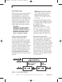
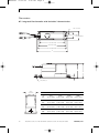
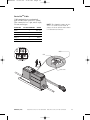
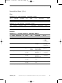
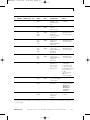
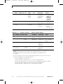
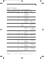
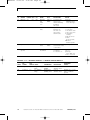
ENT48906
10/15/04
8:12 AM
Page b
NT® INTEGRATED FLOW CONTROLLER
WITH DEVICENET™ COMMUNICATION
User Guide
ENT48906
10/15/04
8:12 AM
Page c
ENT48906
10/15/04
8:12 AM
Page 1
NT® INTEGRATED FLOW CONTROLLER WITH DEVICENET™ COMMUNICATION USER GUIDE
Table of Contents
Introduction .................................. 2
Diagnostic Guide ........................ 17
Identifying Nonstandard
Product Configurations .......... 2
Principle of Operation ............... 2
Maintenance ............................... 19
System Block Diagram .............. 2
Factory Configured .................... 3
Control Mode Functions ............ 3
Autozero Function ..................... 3
Calibration Reference
Conditions ................................ 3
General Considerations .............. 4
Line Pressure .............................. 4
Pressure Drop ............................. 4
Ambient Temperature Range .... 4
Process Temperature Range ..... 4
Storage Temperature Range ..... 4
Power Supply Requirements ..... 4
DeviceNetTM Cable ..................... 5
DeviceNetTM Communication ... 5
Dimensions ................................. 8
Installation .................................... 9
Provided Equipment .................. 9
Mounting Requirements .......... 10
Mechanical Installation .......... 11
Electrical Connections ............ 12
Normal Operation .................... 19
Re-zero Function ...................... 19
Reference .................................... 20
Physical Specifications ............ 20
Power Cable Specifications .... 20
DeviceNetTM Cable
Specifications ........................ 20
Performance Specifications .... 20
Ordering Information ................ 21
Certifications .............................. 22
CE Compliance ......................... 22
ODVA Conformance .................. 22
DeviceNetTM Communication
Integrated Flow Controller ...... 23
Object Model ............................ 23
How Objects Affect Behavior .. 25
Defining Object Interfaces ...... 25
Vendor Specific Section .......... 26
Repair and Warranty Service .... 50
Unit Operation............................. 14
Operating Environment .......... 14
Performance ............................. 14
Reliability Information ............. 16
ENTEGRIS, INC.
Customer Service Tel. 763-502-0200 Customer Service Fax 763-502-0300
1
ENT48906
10/15/04
8:12 AM
Page 2
NT® INTEGRATED FLOW CONTROLLER WITH DEVICENET™ COMMUNICATION USER GUIDE
Introduction
This manual is for use with standard
NT® Integrated Flow Controllers
with DeviceNetTM communication,
Model 6500. These instruments have
been designed for use in high-purity
applications in the semiconductor
industry. The wetted parts are constructed with PTFE, PFA or other
similar high-purity inert materials.
WARNING!
Attempting to install or operate
standard NT® Integrated Flow
Controllers without reviewing the
instructions contained in this
manual could result in personal
injury or equipment damage.
Identifying Nonstandard
Product Configurations
This User Guide applies to product
manufactured as the standard NT®
Integrated Flow Controller. Entegris
also manufactures nonstandard
product to meet the needs of specific
applications. Nonstandard product
may have different materials of construction, accuracy specifications,
performance and other specifications that differentiate the nonstandard product from the standard
offering.
NOTE: Nonstandard NT® Integrated
Flow Controllers may be identified
by the model number found on the
product label. Specifications for
nonstandard NT® Integrated Flow
Controllers are available by contacting Entegris.
Nonstandard NT® Integrated Flow
Controllers, Model 6500 product line,
are identified with an “M” followed
by a number code.
Example part number:
6500-T2-F02-AM6-D-P1-U1-M02
The “M02” designates the product
as a nonstandard product manufactured to certain specifications
designated under the “M02” code.
Principle of Operation
The user provides a set point signal
that corresponds to the desired
amount of flow. The standard NT®
Integrated Flow Controller compares
the set point to the actual flow signal
from the flow module. If the actual
flow is greater than the set point, the
unit closes the valve. If the actual
flow is less than the set point, the
unit opens the valve. The flow controller does this in a precise manner
until the actual flow signal is equal
to the set point.
Figure 1: System block diagram
2
Customer Service Tel. 763-502-0200 Customer Service Fax 763-502-0300
ENTEGRIS, INC.
ENT48906
10/15/04
8:12 AM
Page 3
NT® INTEGRATED FLOW CONTROLLER WITH DEVICENET™ COMMUNICATION USER GUIDE
Factory Configured
The standard NT® Integrated Flow
Controller is pre-configured from the
factory for the flow range specified
by the user. The specified flow range
is found on the label of the unit.
The unit control algorithm uses
pressure and flow measurements
to ensure proper operation within
specification.
Control Mode Functions
There are two types of control mode
functions defined for this product:
Normal Operation: A set point input
of <5% of full scale will cause the
valve to close to a leak tight seal.
This is for batch applications where
the user is dispensing a given flow
rate for a given period of time.
Actuator Override: An actuator
override DeviceNetTM communication message is sent to suspend
control and leave the valve in its
present position, regardless of set
point input value.
will determine DP zero values based
on a weighted average routine.
Calibration Reference
Conditions
Unless otherwise noted, the specifications listed for the NT® Integrated
Flow Controller with DeviceNetTM
communication are referenced under
the following operating conditions:
PARAMETER
REFERENCE CONDITION
Process fluid
Deionized water
Process
temperature
73°F, ± 5°F
(23°C, ± 3°C)
Ambient
temperature
73°F, ± 5°F
(23°C, ± 3°C)
Relative humidity
50% RH, ± 10% RH
Process pressure
20-30 PSIG
(138–207 kPa)
Supply voltage
24 VDC, ± 10%
Warm-up time
5 minutes
Orientation
Horizontal
Operation
Flowmeter zeroed
Autozero Function
If autozero is enabled and the set
point is set to <5%, the valve closes
and the flowmeter will enter into
the re-zero routine. Upon application
of a set point greater than or equal
to 5%, a new differential pressure
(DP) zero value will be stored in
non-volatile memory and the unit
will immediately resume operation.
Autozero is a selectable option
through DeviceNetTM communication
messaging with a default setting of
‘enabled’. It will not increase system
response time. The autozero routine
ENTEGRIS, INC.
Customer Service Tel. 763-502-0200 Customer Service Fax 763-502-0300
3
ENT48906
10/15/04
8:12 AM
Page 4
NT® INTEGRATED FLOW CONTROLLER WITH DEVICENET™ COMMUNICATION USER GUIDE
General
Considerations
NOTE: The flow controller has been
factory sealed. Do not attempt to
remove the cover of the unit. Any
attempt at removal of the unit cover
will void the warranty.
Ambient Temperature Range
The flow controller is designed to
operate in room temperature cleanroom environments: 50° to 86°F (10°
to 30°C). The unit must be re-zeroed
at operating temperature conditions
for the accuracy specifications to
apply.
Line Pressure
Process Temperature Range
The system line pressure (measured
at the inlet of the unit) must be
between 10 and 60 PSIG (69 to 414
kPa). The minimum operating pressure is 10 PSIG (69 kPa).
The range of acceptable process
temperatures is 50° to 149°F (10°
to 65°C). The flow controller must
be re-zeroed at operating temperature conditions for the accuracy
specification to apply. PFA isolators
are recommended for process temperatures higher than 122°F (50°C).
Applications involving hydrofluoric
acid (HF) with temperatures above
86°F (30°C) must contact the
factory for recommended materials
of construction. Positive pressure
must be maintained at all times.
Pressure Drop
The minimum pressure drop (differential pressure) required for the
unit is 10 PSID (69 kPa).
For example, if the flow controller
is operating at an inlet pressure of
15 PSIG (103 kPa) and outputs the
flow to a pressurized canister, which
is pressurized to 10 PSID (69 kPa),
the pressure available to the unit
will be 5 PSID (15 PSIG [103 kPa]
inlet pressure minus 10 PSIG
[69 kPa] canister pressure). This
scenario does not meet the pressure drop requirement of 10 PSID
(69 kPa) and the unit may not
perform within specification. For
this example, either increase the
inlet pressure or decrease the canister pressure to obtain a 10 PSID
(69 kPa) pressure drop.
4
Storage Temperature Range
The flow controller will withstand
storage temperatures between -40°
and +122°F (-40° and 50°C) for at
least a 24-hour period with no permanent effect on device performance.
Power Supply Requirements
The power supply range for the
standard NT® Integrated Flow
Controller is 24 VDC ±10%.
Customer Service Tel. 763-502-0200 Customer Service Fax 763-502-0300
ENTEGRIS, INC.
ENT48906
10/15/04
8:12 AM
Page 5
NT® INTEGRATED FLOW CONTROLLER WITH DEVICENET™ COMMUNICATION USER GUIDE
The power supply must provide
continuous 1.0 A (nominal) current
for each flow controller installed.
Peak power consumption is 1.2 A,
maximum.
The power supply to the flow controller must provide clean power to
the unit and must be used only to
power similar measurement-type
devices. The power supply must not
be used to power other inductive
loads, such as motors, relays or solenoids. These devices may produce
electrical transients that may affect
unit measurements. An induced
power spike, creating an interruption in power greater than 10 msec
in duration, may cause the unit to
reset.
DeviceNetTM Communication
The DeviceNetTM communication
shall meet the physical layer communications requirements in the
referenced ODVA DeviceNetTM standard. Briefly, this is a 5 wire (V+,
V-, CAN_H, CAN_L, Drain) physical
layer based on the CAN protocol.
DeviceNetTM Cable
The power supply range of the
DeviceNetTM cable is 24 VDC ±10%,
150 mA nominal current.
In addition to providing clean power,
all power communication cables
must not be run within the same
conduit or cable along with heavy
current demands from motors,
charging capacitors or other inductive loads. This may cause a voltage
change within the instrumentation
signal line, causing erroneous output
readings from the flow controller.
Loss of power will not cause the loss
of any system parameters or calibration values.
ENTEGRIS, INC.
Customer Service Tel. 763-502-0200 Customer Service Fax 763-502-0300
5
ENT48906
10/15/04
8:12 AM
Page 6
NT® INTEGRATED FLOW CONTROLLER WITH DEVICENET™ COMMUNICATION USER GUIDE
DeviceNetTM Module Status LED
This LED is labeled ‘Mod’.
INTEGRATED FLOW
CONTROLLER STATE
LED STATE
Power off
Off
No power is applied through DeviceNet™.
IFC self-test
Flashing red and green
IFC is in self-test.
IFC operational
Green
IFC is operating normally.
Minor fault
Flashing red
IFC has detected a recoverable fault.
Unrecoverable fault
Red
IFC has detected an unrecoverable fault.
IFC in standby
Flashing green
IFC needs commissioning due to configuration
missing, incomplete or incorrect.
DESCRIPTION
DeviceNetTM Network Status LED
This LED is labeled ‘Net’.
INTEGRATED FLOW
CONTROLLER STATE
LED STATE
DESCRIPTION
Not powered or not on-line
Off
IFC is not on-line. IFC may not be powered;
look at Module Status LED.
On-line, not connected
Flashing green
IFC is on-line, but has no connection.
Link OK, on-line, connected
Green
IFC is on-line and has connection.
Connection time-out
Flashing red
Network connection is in the timed-out state.
Critical link failure
Red
IFC has detected an error and cannot
communicate on the network.
Figure 2: DeviceNet™ switches and
status LEDs located on the top side
of the flow controller
6
Customer Service Tel. 763-502-0200 Customer Service Fax 763-502-0300
ENTEGRIS, INC.
ENT48906
10/15/04
8:12 AM
Page 7
NT® INTEGRATED FLOW CONTROLLER WITH DEVICENET™ COMMUNICATION USER GUIDE
DeviceNetTM Node Address
Switches
Two, ten-position, rotary switches
used for configuring the Media
Access Control Identifier (MACID)
of the flow controller. These switches specify the MACID using decimal
representation. One switch specifies
the most significant digit (MSD), or
tens position of the MACID. The
second switch specifies the least significant digit (LSD) or the ones position of the MACID. DeviceNetTM
allows MACIDs with values 0–63.
The “PGM” label indicates the software programmable switch positions.
Reverse Polarity Protection
The flow controller is reverse polarity
protected; connecting the 24 VDC
power to the incorrect positive and
ground wires will not harm the unit.
To operate properly, the polarity
must be correct.
Over-Voltage on any Wire (DC)
The flow controller will withstand
the continuous application of 30
VDC on any wire without compromising the unit. The flow controller will
withstand the momentary application of 40 VDC on any wire without
compromising the unit.
DeviceNetTM Data Rate Switch
Over-Voltage on any Wire (AC)
A single, ten-position rotary switch
used for configuring the baud rate
of the flow controller. The switch
has positions for the three valid,
DeviceNetTM data rates, 125, 250
and 500 Kbaud. Switch position 0
selects 125 Kb, position 1 selects
250 Kb, and position 2 selects 500
Kb. The “PGM” label indicates the
software programmable switch
positions.
The flow controller is not designed
to withstand the accidental application 110/220 VAC to any wire. Application of AC voltage will damage the
unit.
Short Protection
The flow controller will not be
damaged or compromised in any
way if any combination of wires are
shorted together.
Electrical Isolation
The degree of electrical isolation
between power and DeviceNetTM
communication is as listed below:
From:
To:
Isolation
degree:
Power, 24 VDC
DeviceNet™ Comm
>500 VAC/VDC
ENTEGRIS, INC.
Customer Service Tel. 763-502-0200 Customer Service Fax 763-502-0300
7
ENT48906
10/15/04
8:12 AM
Page 8
NT® INTEGRATED FLOW CONTROLLER WITH DEVICENET™ COMMUNICATION USER GUIDE
Dimensions
NT® Integrated Flow Controller with DeviceNet™ Communication
0.28″ (7.1 mm)
1.85″ (47.03 mm)
2.87″ (72.9 mm)
7.78″ (197.6 mm)
8.53″ (216.7 mm)
9.05″ (229.9 mm)
D
A
B
C
Flared nut (2)
2.58″
(65.5 mm)
8
FITTING
A
B
1⁄4″
C
F02
4.63″
(117.5 mm)
4.89″
(124.2 mm)
0.76″
9.60″
(19.4 mm) (243.8 mm)
3⁄8″
F03
4.63″
(117.5 mm)
4.89″
(124.2 mm)
0.76″
9.75″
(19.4 mm) (247.7 mm)
1⁄2″
F04
4.72″
(119.9 mm)
4.98″
(126.5 mm)
0.85″
(21.6 mm)
3⁄4″
F06
5.02″
(127.5 mm)
5.28″
(134.1 mm)
1.01″
10.15″
(25.7 mm) (257.8 mm)
Customer Service Tel. 763-502-0200 Customer Service Fax 763-502-0300
D
9.91″
(251.7 mm)
ENTEGRIS, INC.
ENT48906
10/15/04
8:12 AM
Page 9
NT® INTEGRATED FLOW CONTROLLER WITH DEVICENET™ COMMUNICATION USER GUIDE
Installation
Provided Equipment
=
CAUTION!
Do not tighten the nuts that
protect the flared tube connections during shipment. (See
Prepare Fluid Lines on page 11).
Tightening these nuts without
the proper tubing installed may
damage the unit’s flared tube
connections.
NOTE: This unit has been assembled
and double-bagged under cleanroom
conditions. To maintain purity, only
open under cleanroom conditions.
Remove Unit from the Bag
ENTEGRIS, INC.
Customer Service Tel. 763-502-0200 Customer Service Fax 763-502-0300
9
ENT48906
10/15/04
8:12 AM
Page 10
NT® INTEGRATED FLOW CONTROLLER WITH DEVICENET™ COMMUNICATION USER GUIDE
Mounting Requirements
The flow controller may be mounted
in any orientation. The unit does not
require straight lengths of tubing at
the inlet or the outlet connection.
Mount the Unit
The flow controller and base
bracket assembly must be
mounted to a solid surface
to ensure stability. Verify the
valve and the electrical cable
are free from mechanical stress
from the surrounding equipment.
NOTE: The flow controller
requires mounting in the
direction of the fluid flow.
Recommended hardware
#10 (M4)
Pan head
#10 (M4)
Flat washer
10
Customer Service Tel. 763-502-0200 Customer Service Fax 763-502-0300
ENTEGRIS, INC.
ENT48906
10/15/04
8:12 AM
Page 11
NT® INTEGRATED FLOW CONTROLLER WITH DEVICENET™ COMMUNICATION USER GUIDE
Mechanical Installation
The standard NT® Integrated Flow
Controller must be used with the
proper tubing size and fittings.
To prepare the fluid lines, begin by
sliding the supplied nuts onto the
fluid tube.
NOTE: Flare each tube end prior to
installation onto the valve fitting.
CAUTION!
Over-tightening of the nuts will
result in damage to the fitting.
Prepare Fluid Lines
Process fluid tube
Slide the nut onto the tube
Process fluid tube
Connect Fluid Lines
Flare each tube end
prior to installation
ENTEGRIS, INC.
Customer Service Tel. 763-502-0200 Customer Service Fax 763-502-0300
11
ENT48906
10/15/04
8:12 AM
Page 12
NT® INTEGRATED FLOW CONTROLLER WITH DEVICENET™ COMMUNICATION USER GUIDE
Electrical Connections
When installing flared tubing to the
flow controller, the flared tube is
pushed over the valve’s fitting until
the fitting reaches the smaller tube
diameter. The amount of torque
required to tighten the nut is dependent upon the size of the fitting.
FITTING SIZE
1⁄4″
3⁄8″
1⁄2″
3⁄4″
Torque (in•lbs.)
5
8
11
14
Torque (N•m)
0.56
0.90
1.24
1.58
Connect cable to flow controller
The cable mounting receptacles are
physically “keyed”, making it impossible to insert the connector improperly. Press it into the mounting
receptacle and rotate the outer
coupling ring to lock the connector
in place. To remove the connector,
rotate the coupling ring in the
opposite direction.
Care should be taken when installing
the flow controller to avoid fluid
leaks. Do not use excessive torque or
subject the unit to high heat during
installation. The unit and base
bracket assembly must be mounted
to a solid surface to ensure stability.
Verify the body and the electrical
cable are free from mechanical stress
from the surrounding equipment.
Power Cable
Cable materials are constructed
with 22 AWG wire and a PVC jacket.
The connector is a 4-pin, 12 mm,
male type.
FUNCTION
PIN ASSIGNMENT
COLOR
No connection
1
Brown
+24V
2
White
24V common
3
Blue
No connection
4
Black
4
5
1
3
2
1
2
3
4
5
Drain
V+ Red
V– Black
CAN_H White
CAN_L Blue
DeviceNet™
communication
cable
12
4
3
1
2
1
2
3
4
N/C
+24V
24V COM
N/C
Power
cable
Customer Service Tel. 763-502-0200 Customer Service Fax 763-502-0300
ENTEGRIS, INC.
ENT48906
10/15/04
8:12 AM
Page 13
NT® INTEGRATED FLOW CONTROLLER WITH DEVICENET™ COMMUNICATION USER GUIDE
DeviceNetTM Cable
Cable materials are constructed
with 22 AWG wire and a PVC jacket.
The connector is a 5-pin, micro-style,
12 mm, male type.
FUNCTION
PIN ASSIGNMENT
COLOR
Drain
1
Bare wire
V+
2
Red
V-
3
Black
CAN_H
4
White
CAN_L
5
Blue
NOTE: The allowable torque on the
8-32 × 1⁄2” PVDF screws used to
secure the clear switch access cover
is 7 Newton-centimeters.
MSD
LSD
Data rate
ENTEGRIS, INC.
Customer Service Tel. 763-502-0200 Customer Service Fax 763-502-0300
13
ENT48906
10/15/04
8:12 AM
Page 14
NT® INTEGRATED FLOW CONTROLLER WITH DEVICENET™ COMMUNICATION USER GUIDE
Unit Operation
Operating Environment
Operating Temperature
The flow controller is designed to
operate in ambient temperature,
cleanroom environments. The unit
is specified to operate at temperatures between 50° and 149°F (10°
and 65°C).
When the process fluid is above
ambient temperatures 73°F (23°C),
the system will experience slight
accuracy errors due to instrument
warm-up and changes in viscosity
and specific gravity of the liquid.
The unit must be re-zeroed after
any temperature change. Please
see the Maintenance Section on
page 19 to perform the re-zero.
Effects of Fluid Viscosity and
Specific Gravity
The flow controller has been factory
calibrated using deionized water.
Fluids with viscosities and/or specific gravity different from the calibration fluid (water) will cause slight
accuracy errors. Correction factors
for viscosity and specific gravity
changes may be obtained from
Entegris by calling or following the
sensing and control product links at
entegrisfluidhandling.com.
Power-up Characteristics
When power is first applied to the
flow controller, the flow will be
within 2% of the set point value in
less than 10 seconds and within
specification after 5 minutes. As
14
part of the power-up routine, the
unit will perform a homing routine
that re-establishes the unit’s fully
closed position. This routine requires
the valve to shut completely for no
more than 8 seconds, then to the position dictated by the set point input.
Unit Enclosure
The standard NT® Integrated Flow
Controller cover is factory sealed
and should not be tampered with or
opened. Spray-down or temporary
immersion will not compromise the
performance of the unit.
NOTE: Any attempt to remove,
tamper or open the flow controller
cover will void the warranty.
Performance
Operating Pressure Requirements
The flow rate is calculated using
Entegris’ differential pressure flow
technology. The minimum operating
pressure is 10 PSIG (69 kPa). The
minimum pressure drop (differential
pressure) required for the flow controller is 10 PSID (69 kPa).
CAUTION!
The flow controller may be
damaged if it is subjected to
any level of vacuum pressure
(less than atmospheric pressure).
NOTE: To perform within specification, the available inlet pressure
must be 10 PSID (69 kPa) greater
than the outlet pressure (10 PSID
[69 kPa] differential pressure).
Customer Service Tel. 763-502-0200 Customer Service Fax 763-502-0300
ENTEGRIS, INC.
ENT48906
10/15/04
8:12 AM
Page 15
NT® INTEGRATED FLOW CONTROLLER WITH DEVICENET™ COMMUNICATION USER GUIDE
Flow Accuracy
Minimum Operating Pressure
The accuracy of the flow measurement is ±1% of full scale from 20100% of the flow range. The accuracy
of the flow measurement is ±2.5% of
full scale from 10-20% of the flow
range. The accuracy specification includes the effects of linearity, hysteresis and repeatability, using
deionized water at 73°F (23°C). The
accuracy between 0-10% of full scale
flow range is not specified.
The unit will operate within specification at any inlet pressure within
the range of 10-60 PSIG (69 to 414
kPa) and a minimum pressure drop
of 10 PSID (69 kPa).
Flow accuracy is verified by testing
the unit at stable conditions for a
period of 20 seconds or longer.
To meet the accuracy specification, a
re-zero is required for every 10 PSIG
(69 kPa) change in line pressure.
Pulsating Inlet Pressure
Some applications use pumps (diaphragm pumps for example) that
can cause significant and rapid
change in pressure. The flow controller shall meet the accuracy specification under the following conditions: pressure pulsation frequency
0-2 Hz, pressure pulsation amplitude
10 PSIG (69 kPa) and 60 second
batch test.
Response Time
Temperature Increase of Flow
Controller Enclosure
Response time is defined as the
length of time required for the measured flow rate to be within the full
scale (FS) accuracy specification.
The typical response time is within
3 seconds.
The temperature increase within the
unit enclosure will be less than 86°F
(30°C). The temperature increase at
the exterior of the unit cover will be
less than 77°F (25°C).
The flow controller will respond to
set point changes within 50 msec of
receiving the new set point value.
When power is first applied to the
unit, such as during a start-up
sequence, the flow rate will be
controlled to within 1% FS of the
set point value within 10 seconds.
Pressure Measurement Accuracy
The accuracy of the pressure output
is ±1% of full scale. These calculations include the effects of linearity,
hysteresis and repeatability, measured at 73°F (23°C).
ENTEGRIS, INC.
The temperature increase of the
process fluid will be less than 5°F
(3°C) at 10% of flow and less than
0.9°F (0.5°C) at 100% of flow range
for T1, T2, T3 and T4 flow ranges.
For all other flow ranges, the temperature rise of the process fluid is
negligible, less than 0.9°F (0.5°C),
at all flows. Under extended static
flow conditions (i.e., no flow for >24
hours) the temperature increase of
the process fluid will be less than
27°F (15°C).
Customer Service Tel. 763-502-0200 Customer Service Fax 763-502-0300
15
ENT48906
10/15/04
8:12 AM
Page 16
NT® INTEGRATED FLOW CONTROLLER WITH DEVICENET™ COMMUNICATION USER GUIDE
Warm-up Time
Enclosure Integrity
The flow controller requires a warmup time of 10 minutes after power is
applied. Warm-up time is typically
not required if the unit was operated
within 3 hours.
Momentary immersion and spray
down of the flow controller will not
affect the performance per NEMA 5
and IP56.
Drop and Topple
Reliability Information
Redundant Process Seals
All internal process wetted seals are
redundant, i.e., there is a secondary
seal that prevents process fluid from
reaching the interior of the device in
the case of a primary seal failure.
Weep holes are provided from the
secondary containment regions.
If the unit topples over from a 45degree angle onto a bench top, the
performance will not be compromised and the unit will not be externally damaged.
Cable Pull
The cable will withstand a static pull
test of 20 lbs (9.1 kg) straight and
10 lbs (4.5 kg) at 90 degrees without
being damaged.
Long-term Reliability
The valve system can withstand
3.5 million open/close cycles before
the control performance is compromised.
16
Customer Service Tel. 763-502-0200 Customer Service Fax 763-502-0300
ENTEGRIS, INC.
ENT48906
10/15/04
8:12 AM
Page 17
NT® INTEGRATED FLOW CONTROLLER WITH DEVICENET™ COMMUNICATION USER GUIDE
Diagnostic Guide
SYMPTOM
POSSIBLE CAUSES
SUGGESTIONS
1. Flow reading is
very low.
The unit is installed
backwards.
Install the unit so the inlet flow
is plumbed on the same side as
the electrical connection.
Insufficient line pressure.
The inlet pressure must be at
least 10 PSIG (69 kPa) greater
than the outlet pressure. Verify
the inlet pressure using the pressure signal from the flow controller.
2. Flow reading
above zero when
set point is zero
and no flow is
present.
The unit needs to be
re-zeroed.
Perform a zero adjust service or
enable the autozero function.
3. Flow output is
extremely noisy
The actual fluid flow
conditions are noisy.
Flow turbulence may be caused
by “noisy” pumps used in a
system. Examples of noisy
pumps are diaphragm pumps
without pulsation dampeners
and peristaltic pumps operating
at low flow rates. Please contact
Entegris for additional information.
4. Unit resets.
The supply power
(+24V) is noisy.
If the power supply is shared
with other systems, components
such as solenoids, DC motors,
valves, etc., the unit may be receiving “dirty” power. Extreme
noise spikes will cause the unit
to reset. Connect the unit to a
separate power source.
5. Flow output does
not correspond to
set point for high
flow rates.
Inlet pressure is not 10 PSIG
(69 kPa) greater than the
outlet pressure at the high
flow conditions.
Measure the inlet pressure. Also
measure the fluid pressure at the
outlet of the unit using a pressure gauge or pressure transducer. Verify the inlet pressure is at
least 10 PSIG (69 kPa) greater
than the outlet pressure.
ENTEGRIS, INC.
Customer Service Tel. 763-502-0200 Customer Service Fax 763-502-0300
17
ENT48906
10/15/04
8:12 AM
Page 18
NT® INTEGRATED FLOW CONTROLLER WITH DEVICENET™ COMMUNICATION USER GUIDE
Diagnostic Guide (continued)
SYMPTOM
POSSIBLE CAUSES
SUGGESTIONS
6. Flow rate is not
meeting desired
set point within
10 seconds or
longer.
The unit is receiving a set
point signal with no fluid
flow present. The flow controller valve is moved to the
full-open position. Depending
upon flow range, the unit
may require 10–15 seconds
or more to move from the
full-open position to the
correct set point position.
Do not send a set point signal
to the unit when no fluid flow is
available.
Inlet pressure is not 10 PSIG
(69 kPa) greater than outlet
pressure.
(see above, Symptom 5)
7. Flow output is not
responsive to
changes in set
point signal.
Valve in full-open position.
If the unit is plumbed
between two closed valves,
the unit may stall in the fullopen position when the unit
is commanded to close.
Since a fixed volume of fluid
is incompressible, the unit
may stall when attempting
to close if upstream and
downstream valves are
closed.
Avoid conditions of simultaneously closed valves upstream
and downstream of the unit.
The unit can be returned to
normal operation by performing
a re-zero, or by cycling power.
8. Net LED flashes
green. Valve goes
to safe position,
default position is
closed.
Network down
Reconnect to network
18
Customer Service Tel. 763-502-0200 Customer Service Fax 763-502-0300
ENTEGRIS, INC.
ENT48906
10/15/04
8:12 AM
Page 19
NT® INTEGRATED FLOW CONTROLLER WITH DEVICENET™ COMMUNICATION USER GUIDE
Maintenance
Normal Operation
During normal operation, the standard NT® Integrated Flow Controller
with DeviceNetTM communication requires no maintenance, other than a
periodic re-zero of the unit.
Re-zero Function
The no flow calibration of the flow
controller can be re-zeroed, meaning
that the flow output that corresponds
to zero flow may be reset.
NOTE: When executing the re-zero
function, there must be at least
1 PSIG (7 kPa) of static pressure.
Optimum pressure for re-zero is the
operation pressure, typically greater
than 10 PSIG (69 kPa).
NOTE: The following procedure
must be followed precisely to
ensure proper flow controller
re-zero.
The no flow calibration of the
flow controller can be re-zeroed,
meaning that the flow output that
corresponds to zero flow may be internally reset. This is done with
DeviceNetTM service requests. The
‘Zero_Adjust’ service command in
the Analog Sensor Object is sent
to begin a re-zero process. The
‘Stop_Zero_Adjust’ service command
in the Analog Sensor Object is sent
to stop the re-zero process.
ENTEGRIS, INC.
When the re-zero function is activated, the flow controller valve module
will close fully to ensure that fluid is
not flowing. The unit will verify the
no-flow condition, and then re-zero
the flow module. The entire re-zero
function is completed in 10 seconds.
In order to obtain best performance,
the re-zero function should be performed, at minimum if possible, every
30 days of service when operating at
ambient temperature conditions.
The re-zero function should be performed more often if operating at
higher temperature. It is also recommended to perform a re-zero after
start-up and after fluid temperature
changes of greater than 9°F (5°C).
Best performance will be achieved
by re-zeroing between each dispense
cycle.
Autozero Function
The no flow calibration of the
flow controller can be autozeroed,
meaning that the flow output that
corresponds to zero flow may be
automatically, internally reset whenever the set point is zero. Selecting
the ‘enabled’ setting of the ‘Autozero
Enable’ attribute in the Analog
Sensor Object does this. This is the
default setting.
Customer Service Tel. 763-502-0200 Customer Service Fax 763-502-0300
19
ENT48906
10/15/04
8:12 AM
Page 20
NT® INTEGRATED FLOW CONTROLLER WITH DEVICENET™ COMMUNICATION USER GUIDE
Reference
Physical Specifications
PART
CONSTRUCTION MATERIALS
Wetted parts:
Body:
Diaphragms:
Sensor interface:
O-rings:
Nonwetted parts:
Connection type:
Enclosure:
PTFE
PTFE
PFA or CTFE
Kalrez® 4079
Polypropylene cover and base plate, Viton® plugs
Flaretek® tube fitting
NEMA 5/IP54
Power Cable Specifications
Input voltage:
Input current:
Electrical connection:
24 VDC, ±10%
1.0 A nominal, 1.2 A peak
6′, 12′ lengths with 22 ga wire
PVC-jacketed wire
DeviceNetTM Cable Specifications
Input voltage:
Input current:
Electrical connection:
24 VDC, ±10%
150 mA nominal
6′, 12′ lengths with 22 ga wire
PVC-jacketed wire
Performance Specifications
Flow accuracy:
Pressure accuracy:
Repeatability:
Response time:
Process temperature:
Storage temperature:
Operating pressure:
Over-pressure limit:
±1.0% FS at 20% to 100% of flow range,
±2.5% FS at 10% to 20% of flow range.
Accuracy defined for 10 seconds average,
using DI water at 73°F (23°C).
Accuracy not specified 0% to 10% of flow range.
±1.0% FS (full scale is 60 PSIG [414 kPa])
±0.5% FS at 20% to 100% of flow range
±1.0% FS at 10% to 20% of flow range
<3 seconds to within 5% of new set point value
50° to 149°F (10° to 65°C)
-40° to 122°F (-40° to 50°C)
10 to 60 PSIG (69 to 414 KPA)
100 PSIG (690 KPA)
NOTE: Specifications are subject to change without notice. Please consult the
factory for the most current information.
20
Customer Service Tel. 763-502-0200 Customer Service Fax 763-502-0300
ENTEGRIS, INC.
ENT48906
10/15/04
8:12 AM
Page 21
NT® INTEGRATED FLOW CONTROLLER WITH DEVICENET™ COMMUNICATION USER GUIDE
Ordering Information
MODEL
6500
PRODUCT DESCRIPTION
CODE
ELECTRICAL CONNECTOR TYPE
Integrated Flow Controller
AM6
PVC-jacketed 6′ cable set
AM12
PVC-jacketed 12′ cable set
CODE
SET POINT INPUT SIGNAL,
CONTROLLER TYPE
CODE
FLOW RANGE
T0
T1
T2
T3
T4
T5
T6
T7
T8
T9
CODE
0-50 ml/min.
0-125 ml/min.
0-250 ml/min.
0-500 ml/min.
0-1250 ml/min.
0-2.5 l/min.
0-5 l/min.
0-10 l/min.
0-20 l/min.
0-40 l/min.*
D
CODE
F02
Flaretek® tube fitting
F03
3⁄8˝
Flaretek® tube fitting
F04
1⁄2˝
Flaretek® tube fitting
F06
3⁄4˝
Flaretek® tube fitting
SENSOR INTERFACE
P1
CTFE
P2
PFA
CODE
PROCESS CONNECTION
1⁄4˝
DeviceNet™ communication
PRIMARY / SECONDARY SEAL
U1
Kalrez® 4079 / Viton® (default)
U2
Kalrez® 1050 LF / Viton®
U3
Kalrez® 6375 UP / Viton®
* Please consult factory for operating pressure requirement.
Allowed process connection and flow range combinations:
FLOW RANGE
T0
T1
T2
T3
T4
1⁄4″
F02
✓
✓
✓
✓
✓
3⁄8″
F03
✓
✓
✓
✓
✓
1⁄2″
F04
—
—
—
✓
✓
3⁄4″
F06
—
—
—
—
—
ENTEGRIS, INC.
T5
T6
T7
T8
T9
—
—
—
—
—
✓
✓
—
—
—
✓
✓
✓
✓
—
—
—
✓
✓
✓
Customer Service Tel. 763-502-0200 Customer Service Fax 763-502-0300
21
ENT48906
10/15/04
8:12 AM
Page 22
NT® INTEGRATED FLOW CONTROLLER WITH DEVICENET™ COMMUNICATION USER GUIDE
Certifications
ODVA Conformance
CE Compliance
Entegris products have been tested
to various test standards required by
the EMC 89/336/EEC directive. The
results of this testing are on file at
Entegris and are available upon
request.
Please contact the factory for the
latest information. The most current
specifications may be found on the
Internet at:
http://www.entegrisfluidhandling.com.
22
NT®
The
Integrated Flow Controller
with DeviceNetTM communication has
successfully completed and passed
Open DeviceNet Vendor Association
(ODVA) approved conformance tests
at the independent, authorized ODVA
Training and Technology Center in
Ann Arbor, MI. Entegris has been
issued an official Declaration of
Conformity from ODVA for this
product.
Customer Service Tel. 763-502-0200 Customer Service Fax 763-502-0300
ENTEGRIS, INC.
ENT48906
10/15/04
8:12 AM
Page 23
NT® INTEGRATED FLOW CONTROLLER WITH DEVICENET™ COMMUNICATION USER GUIDE
DeviceNetTM Communication Integrated Flow
Controller Device
Device Type: 00 hex
controlled to the set point.
This vendor specific device profile
is based on the DeviceNetTM Fluid
Flow Controller (FFC) device profile.
The device type is 00 due to the prerelease status of the FFC profile.
Type 00 is a Generic Device type.
This chapter contains two primary
sections. First, the device profile is
specified as it appears in general
DeviceNetTM specification. Second,
the vendor specific attributes, services, behaviors, ranges and capabilities are specified.
A Fluid Flow Controller (FFC) is a
device that measures and controls
the flow rate of a fluid (liquid or
gas). It contains three principle components: a flow rate sensor that can
be a virtual sensor based on other
sensors, for example pressure; a fluid
flow metering valve that can be actuated by one of a variety of actuator
types, including, for example, solenoid or a stepper motor; and, a controller that closes the loop by receiving a set point and driving the actuator such that the fluid flow rate is
Object Model
The Object Model in Table 1 represents an FFC Device. The table below
indicates:
• The object classes present in
this device
• Whether or not the class is
required
• The number of instances present
in each class
Table 1. Object Model
OBJECT CLASS
OPTIONAL/REQUIRED
# OF INSTANCES
Identity
Required
1
Message router
Required
1
DeviceNet™
Required
1
Connection
Required
at least 1 I/O and 1 explicit
Assembly
Required
at least 1 input and 1 output
S-Device supervisor
Required
1
S-Sensor calibration
Optional
0 or more
S-Analog sensor
Required
2
S-Analog actuator
Required
1
S-Single stage controller
Required
1
ENTEGRIS, INC.
Customer Service Tel. 763-502-0200 Customer Service Fax 763-502-0300
23
ENT48906
10/15/04
8:12 AM
Page 24
NT® INTEGRATED FLOW CONTROLLER WITH DEVICENET™ COMMUNICATION USER GUIDE
DeviceNet™ Communication
Hierarchy of Semiconductor
Equipment Device Objects
S-Analog Sensor Class
S-Single Stage
Controller
Pressure
S-Analog
Actuator
Flow
S-Sensor
Calibration
S-Device
Supervisor
Identity
Message
Router
Assembly
DeviceNet™
Connection Class
I/O
Explicit
Message
DeviceNet™
Figure 3. Object model for the FFC device
S-ANALOG SENSOR
NAME
DESCRIPTION
Instance 1
Flow
Virtual sensor that calculates the fluid flow
rate based on various sensed parameters,
for example, differential pressure
Instance 2
Pressure
The measured fluid pressure
24
Customer Service Tel. 763-502-0200 Customer Service Fax 763-502-0300
ENTEGRIS, INC.
ENT48906
10/15/04
8:12 AM
Page 25
NT® INTEGRATED FLOW CONTROLLER WITH DEVICENET™ COMMUNICATION USER GUIDE
How Objects Affect Behavior
OBJECT
AFFECT ON BEHAVIOR
Identity
Supports the Reset service. Upon receipt of a Reset Service
Request of any Type, the Identity Object sends a Reset
Service Request to the S-Device supervisor.
Message router
No effect
DeviceNet™
Configures port attributes (node address, data rate and BOI
[Bus-Off Interrupt])
Connection class
Contains the number of logical ports into or out of the device
Assembly
Defines input/output and configuration data format
S-Device supervisor
Supports the Stop, Start, Reset, Abort, Recover and
Perform_Diagnostic services for ALL Application Objects in
the device and consolidates the Exception Conditions and
Application Objects’ Status.
This object behaves differently from the Identity Object in
that the S-Device supervisor object provides a single point
of access to the Application Objects only; it does not affect
the DeviceNet™ specific objects (i.e., Identity, DeviceNet™,
Connection, etc.).
S-Sensor calibration
Modifies the correction algorithm of the Flow S-Analog
Sensor object, which includes the selection mechanism to
enable an S-Sensor Calibration object instance.
S-Analog Sensor
A virtual sensor determines the measured fluid flow rate.
The flow sensor feeds the process variable to the S-Single
Stage Controller object
S-Single stage controller
Feeds the control variable to the S-Analog Actuator object
S-Analog actuator
Operates the Flow Control Valve of the device
Defining Object Interfaces
OBJECT
INTERFACE
Identity
Message router
Message router
Explicit messaging connection instance
DeviceNet™
Message router
Connection class
Message router
Assembly
I/O connection or message router
S-Device supervisor
Assembly or message router
S-Sensor calibration
Message router
S-Analog sensor
Assembly or message router
S-Single stage controller
Assembly or message router
S-Analog actuator
Assembly or message router
ENTEGRIS, INC.
Customer Service Tel. 763-502-0200 Customer Service Fax 763-502-0300
25
ENT48906
10/15/04
8:12 AM
Page 26
NT® INTEGRATED FLOW CONTROLLER WITH DEVICENET™ COMMUNICATION USER GUIDE
Vendor Specific Section
This section specifies the Vendor
Specific attributes, service and behaviors supported by this device.
It is provided primarily to specify
which attributes and services are
supported and with what ranges.
NOTE: Specific definitions of attributes and services are included here
for reference only. For specification
details and latest revisions, see the
DeviceNet™ Specifications.
NOTE: Attribute Tables that include
an "NV" column use the following
nomenclature:
V = Volatile: value is lost upon
power cycle
NV = Nonvolatile: value is retained
through power cycle. A “Reset
Type 1” reinitializes these
values to their defaults (i.e.,
Out-of-Box configuration).
NVF = Nonvolatile Factory Set: value
is retained through power
cycle. Only the factory can
change these values with
special software access. A
“Reset Type 1” has no affect
on these values.
NVC = Nonvolatile Constant: value
is fixed, determined by software. These values are “hardcoded” and not settable.
Identity Object (01hex)
Class
ATTRIBUTES 1.0 - CLASS ATTRIBUTES - IDENTITY OBJECT
ATT. ID
REQUIRED
SUPPORTED
ACCESS
RULE
1
Optional
Yes
Get
NAME
DATA
TYPE
ATTRIBUTE
DESCRIPTION
Revision
UINT
Object Revision
VALUES
= 01
SERVICES 1.0 - CLASS SERVICES - IDENTITY OBJECT
CODE
REQUIRED
SUPPORTED
0Ehex
Required
Yes
26
NAME
Get_Attribute_
Single
PARAMETERS
DESCRIPTION
Attribute ID
(USINT)
Retrieves an
attribute value
Customer Service Tel. 763-502-0200 Customer Service Fax 763-502-0300
PARAMETER
VALUES
1–255
ENTEGRIS, INC.
ENT48906
10/15/04
8:12 AM
Page 27
NT® INTEGRATED FLOW CONTROLLER WITH DEVICENET™ COMMUNICATION USER GUIDE
Instance 1
ATTRIBUTES 1.1 - INSTANCE ATTRIBUTES - IDENTITY OBJECT 1
ATT. REID QUIRED
SUPACCESS
PORTED RULE NV
NAME
DATA
TYPE
ATTRIBUTE
DESCRIPTION
VALUES
1
Required Yes
Get
NVC
Vendor ID
UINT
ODVA assigned 864 =
identification
NT International
of vendor
2
Required Yes
Get
NVC
Device
type
UINT
Indication of
general type
of product
3
Required Yes
Get
NVF
Product
code
UINT
Indication of a 0001
particular product of an individual vendor
4
Required Yes
Get
NVC
0000
Revision
STRUCT of:
Major revision
USINT
01
Minor revision
USINT
01
5
Required Yes
Get
V
Status
WORD
Summary
status of
device
b0 = Owned
b1 = 0
b2 = Configured
b3 = 0
b4 : b7 = 0
b8 = Minor recoverable fault
b9 = Minor unrecoverable fault
b10 = Major recoverable fault
b11 = Major unrecoverable fault
b12 : b15 = 0
6
Required Yes
Get
NVF
Serial number
UDINT
Serial number
of device
Must be
guaranteed
unique for a
given Vendor ID
7
Required Yes
Get
NVF
Product name
SHORT_
STRING
Human
readable
identification
“FFC”
ENTEGRIS, INC.
Customer Service Tel. 763-502-0200 Customer Service Fax 763-502-0300
27
ENT48906
10/15/04
8:12 AM
Page 28
NT® INTEGRATED FLOW CONTROLLER WITH DEVICENET™ COMMUNICATION USER GUIDE
SERVICES 1.1 - INSTANCES SERVICES - IDENTITY OBJECT 1
CODE
REQUIRED
SUPPORTED
0Ehex
Required
Yes
05hex
Required
Yes
NAME
PARAMETER
VALUES
PARAMETERS
DESCRIPTION
Get_Attribute_
Single
Attribute ID
(USINT)
Retrieves an
attribute value
Reset
Type (USINT)
Emulates power
Type 0 = Reset.
cycling the device. [default if parameter is omitted]
1–255
Type 1= Return to
the out–of–box
configuration,
then Reset.
Message Router Object (02hex)
Class
ATTRIBUTES 2.0 - CLASS ATTRIBUTES - MESSAGE ROUTER OBJECT
ATT. ID
REQUIRED
SUPPORTED
ACCESS
RULE
1
Optional
Yes
Get
NAME
DATA
TYPE
ATTRIBUTE
DESCRIPTION
VALUES
Revision
UINT
Object Revision
= 01
SERVICES 2.0 - CLASS SERVICES - MESSAGE ROUTER OBJECT
CODE
REQUIRED
SUPPORTED
0Ehex
Required
Yes
NAME
Get_Attribute_
Single
PARAMETERS
DESCRIPTION
Attribute ID
(USINT)
Retrieves an
attribute value
PARAMETER
VALUES
1–255
Instance 1
NO INSTANCE ATTRIBUTES
NO INSTANCE SERVICES
28
Customer Service Tel. 763-502-0200 Customer Service Fax 763-502-0300
ENTEGRIS, INC.
ENT48906
10/15/04
8:12 AM
Page 29
NT® INTEGRATED FLOW CONTROLLER WITH DEVICENET™ COMMUNICATION USER GUIDE
DeviceNetTM Object (03hex)
Class
ATTRIBUTES 3.0 - CLASS ATTRIBUTES - DEVICENET™ OBJECT
ATT. ID
REQUIRED
SUPPORTED
ACCESS
RULE
1
Optional
Yes
Get
NAME
DATA
TYPE
ATTRIBUTE
DESCRIPTION
VALUES
Revision
UINT
Object revision
= 02
SERVICES 3.0 - CLASS SERVICES - DEVICENET™ OBJECT
CODE
REQUIRED
SUPPORTED
0Ehex
Required
Yes
NAME
Get_Attribute_
Single
PARAMETER
VALUES
PARAMETERS
DESCRIPTION
Attribute ID
(USINT)
Retrieves an
attribute value
1–255
Instance 1
ATTRIBUTES 3.1 - INSTANCE ATTRIBUTES - DEVICENET™ OBJECT 1
ATT. REID QUIRED
SUPACCESS
PORTED RULE NV
NAME
DATA
TYPE
ATTRIBUTE
DESCRIPTION
VALUES
1
Optional Yes
Get *
NV * MACID
USINT
Node address
= 0–63
2
Optional Yes
Get *
NV * Baud Rate
USINT
Baud rate
0 = 125K
1 = 250K
2 = 500K
3 = undefined
3
Optional Yes
Get
NV
BOI
BOOL
Bus-off
interrupt
0 = Hold bus-off
[default]
1 = Auto reset
(not supported)
5
Required Yes
Get
V
Allocation
Info
Struct of:
BYTE
USINT
Allocation Choice
Masters MACID
See service
parameter
6
Required Yes
Get
V
MACID
Swt Chg
BOOL
Changed since
last reset
(media access)
0 = No change
1 = Changed
7
Required Yes
Get
V
BAUD
Swt Chg
BOOL
Changed since
last reset
(media access)
0 = No change
1 = Changed
8
Required Yes
Get
V
MACID
Swt Chg
USINT
Actual switch
value
0–99
9
Required Yes
Get
V
BAUD
Swt Chg
USINT
Actual switch
value
0–9
* If the corresponding configuration switch is higher than the attribute's limit, the attribute has SET access.
ENTEGRIS, INC.
Customer Service Tel. 763-502-0200 Customer Service Fax 763-502-0300
29
ENT48906
10/15/04
8:12 AM
Page 30
NT® INTEGRATED FLOW CONTROLLER WITH DEVICENET™ COMMUNICATION USER GUIDE
SERVICES 3.1 - INSTANCE SERVICES - DEVICENET™ OBJECT 1
PARAMETER
VALUES
CODE REQUIRED SUPPORTED NAME
PARAMETERS
DESCRIPTION
0Ehex Required
Yes
Get_Attribute_
Single
Attribute ID
(USINT)
Retrieves an
attribute value
1–255
10hex Required
Yes
Set_Attribute_
Single
Attribute ID
(USINT); Value
Sets an
attribute value
Attribute ID = 1–255
Value = attribute
specific
4Bhex Required
Yes
Allocate_Master/ Allocation
Initializes
Slave_Connection choice; Master predefined
_Set
master/slave
connection set
0 × 01= Explicit
0 × 02 = Poll
0 × 03 = Both
4Chex Required
Yes
Release_Group_2 Allocation
_Identifier_Set
choice
0 × 01= Explicit
0 × 02 = Poll
0 × 03 = Both
Releases
predefined
master/slave
connection set
SERVICES DATA FIELD PARAMETERS
PARAMETER
REQUIRED
DATA TYPE
DESCRIPTION
VALUES
Allocation choice
Yes
BYTE
Specifies the
connection types
b0 = Explicit
b1 = Polled
b2 = Bit strobe
b3 = Multicast poll
b4 = COS
b5 = Cyclic
b6 = Ack suppress
b7 = Reserved
Master
Yes
USINT
Master's MACID
= 0-63
Allocate success
response
Yes
BYTE
Message body format
(number of bits for
Class/Instance identifiers)
0 = 8/8 [default]
1 = 8/16
2 = 16/16
3 = 16/8
Assembly Object (04hex)
Class
ATTRIBUTES 4.0 - CLASS ATTRIBUTES - ASSEMBLY OBJECT
ATT. REID QUIRED
1
SUPACCESS
PORTED RULE NV
Optional Yes
NAME
DATA
TYPE
ATTRIBUTE
DESCRIPTION
VALUES
Get
NVC
Revision
UINT
Object revision
= 02
100 Vendor
specific
Yes
Set
NV
Default
I/O consume
USINT
Default output
assembly inst ID
= 10, 11
[default] = 10
101 Vendor
specific
Yes
Set
NV
Default
I/O produce
USINT
Default input
assembly inst ID
= 1, 2, 3, 6
[default] = 2
30
Customer Service Tel. 763-502-0200 Customer Service Fax 763-502-0300
ENTEGRIS, INC.
ENT48906
10/15/04
8:12 AM
Page 31
NT® INTEGRATED FLOW CONTROLLER WITH DEVICENET™ COMMUNICATION USER GUIDE
SERVICES 4.0 - CLASS SERVICES - ASSEMBLY OBJECT
CODE
REQUIRED
SUPPORTED NAME
0Ehex
Required
Yes
10hex
Required
Yes
PARAMETER
VALUES
PARAMETERS
DESCRIPTION
Get_Attribute_
Single
Attribute ID
(USINT)
Retrieves an
attribute value
1–255
Set_Attribute_
Single
Attribute ID
(USINT); Value
Sets an
attribute value
Attribute ID = 1–255
Value = attribute
specific
Instances
Instance Identifiers
4.N ASSEMBLY OBJECT INSTANCES
NUMBER
REQUIRED
TYPE
1
Y
Input
ELEMENTS
Flow
2
Y (default)
Input
Status and flow
3
N
Input
Status, flow and pressure
6
N
Input
Status, flow, pressure and valve
10
Y (default)
Output
Set point
11
Y
Output
Override and set point
Element Mapping
ASSEMBLY OBJECT ELEMENT MAPPING
CLASS
ATTRIBUTE
DATA COMPONENT NAME
NAME
NUMBER
INSTANCE
NUMBER
NAME
NUMBER
TYPE
Flow
S-Analog sensor
31hex
1
Value
6
INT
Pressure
S-Analog sensor
31hex
2
Value
6
INT
Valve
S-Analog actuator
32hex
1
Value
6
INT
Override
S-Analog actuator
32hex
1
Override
5
USINT
Set point
S-Single stage
controller
33hex
1
Set point
6
INT
Status
S-Device
supervisor
30hex
1
Exception
status
12
BYTE
ENTEGRIS, INC.
Customer Service Tel. 763-502-0200 Customer Service Fax 763-502-0300
31
ENT48906
10/15/04
8:12 AM
Page 32
NT® INTEGRATED FLOW CONTROLLER WITH DEVICENET™ COMMUNICATION USER GUIDE
Instances 1-n
ATTRIBUTES 4.N - INSTANCE ATTRIBUTES - ASSEMBLY OBJECT
ATT. ID
REQUIRED SUPPORTED
ACCESS
RULE
NAME
3
Required
Get
Yes
Data
ATTRIBUTE DESCRIPTION
The I/O Assembly DATA attribute is formatted
as a structure of data elements with the First
element (elements are listed in the "Instance
Identifiers" table) ordered first. All data
components are encoded with the Lowordered Byte first; (i.e., the Least Significant
Byte, LSB, is in the Low-ordered Index,
Address) also known as Little Endian.
SERVICES 4.N - INSTANCE SERVICES - ASSEMBLY OBJECT
CODE
REQUIRED
SUPPORTED
0Ehex
Required
Yes
NAME
Get_Attribute_
Single
PARAMETERS
DESCRIPTION
Attribute ID
(USINT)
Retrieves an
attribute value
PARAMETER
VALUES
1–255
Connection Object (05hex)
Class
ATTRIBUTES 5.0 - CLASS ATTRIBUTES - CONNECTION OBJECT
ATT. ID
REQUIRED
SUPPORTED
ACCESS
RULE
1
Optional
Yes
Get
NAME
DATA
TYPE
ATTRIBUTE
DESCRIPTION
VALUES
Revision
UINT
Object revision
= 01
SERVICES 5.0 - CLASS SERVICES - CONNECTION OBJECT
CODE
REQUIRED
SUPPORTED
0Ehex
Required
Yes
32
NAME
Get_Attribute_
Single
PARAMETERS
DESCRIPTION
Attribute ID
(USINT)
Retrieves an
attribute value
Customer Service Tel. 763-502-0200 Customer Service Fax 763-502-0300
PARAMETER
VALUES
1–255
ENTEGRIS, INC.
ENT48906
10/15/04
8:12 AM
Page 33
NT® INTEGRATED FLOW CONTROLLER WITH DEVICENET™ COMMUNICATION USER GUIDE
Instance 1 - Explicit
ATTRIBUTES 5.1 - INSTANCE ATTRIBUTES - CONNECTION OBJECT 1
ATT. REID QUIRED
SUPACCESS
PORTED RULE
NAME
DATA
TYPE
ATTRIBUTE
DESCRIPTION
VALUES
1
Required Yes
Get
State
USINT
Object state
00 = Non-existent
01 = Configuring
02 = Waiting for conn ID
03 = Established
04 = Timed out
05 = Deferred delete
2
Required Yes
Get
Instance
type
USINT
= Explicit
= 00
3
Required Yes
Get
Trans
Class/Trig
USINT
= Server Class 3
= 0×83
4
Required Yes
Get
P Conn ID
UINT
Exp Resp. CAN ID
= 10xxxxxx011;
x = MACID
5
Required Yes
Get
C Conn ID
UINT
Exp Req. CAN ID
= 10xxxxxx100;
x = MACID
6
Required Yes
Get
Initial Comm BYTE
characteristics
Group IDs
= 0×21
7
Required Yes
Get
P Conn size
UINT
Maximum data
production size
= 40
8
Required Yes
Get
C Conn size
UINT
Maximum data
consumption size
= 40
9
Required Yes
Set
EPR
UINT
Expected packet
rate in
milliseconds
2500 = Default
12
Required Yes
Set
WTO action
USINT
Watch dog
timeout Action
00 = Time out
(not supported)
01 = Auto delete [default]
02 = AutoReset
(not supported)
03 = Deferred delete
13
Required Yes
Get
P Conn Path
Length
UINT
Path length
= 00
14
Required Yes
Get
P Conn Path
EPATH
Path from which
connection
produces
= Empty
15
Required Yes
Get
C Conn Path
length
UINT
Path length
= 00
16
Required Yes
Get
C Conn Path
EPATH
Path to which
connection
consumes
= Empty
ENTEGRIS, INC.
Customer Service Tel. 763-502-0200 Customer Service Fax 763-502-0300
33
ENT48906
10/15/04
8:12 AM
Page 34
NT® INTEGRATED FLOW CONTROLLER WITH DEVICENET™ COMMUNICATION USER GUIDE
SERVICES 5.1 - INSTANCE SERVICES - CONNECTION OBJECT 1
CODE
REQUIRED
SUPPORTED NAME
0Ehex
Required
Yes
10hex
Required
Yes
PARAMETER
VALUES
PARAMETERS
DESCRIPTION
Get_Attribute_
Single
Attribute ID
(USINT)
Retrieves an
attribute value
1–255
Set_Attribute_
Single
Attribute ID
(USINT); Value
Sets an
attribute value
Attribute ID = 1–255
Value = attribute
specific
Instance 2 - Polled
ATTRIBUTES 5.2 - INSTANCE ATTRIBUTES - CONNECTION OBJECT 2
ATT. REID QUIRED
SUPACCESS
PORTED RULE
NAME
DATA
TYPE
ATTRIBUTE
DESCRIPTION
VALUES
1
Required Yes
Get
State
USINT
Object state
See Instance 1
2
Required Yes
Get
Instance type
USINT
= Poll
= 01
3
Required Yes
Get
Trans Class/
Trig
USINT
= Server Class 2
= 0×82
4
Required Yes
Get
P Conn ID
UINT
Poll Resp. CAN ID
= 01111xxxxxx;
x = MACID
5
Required Yes
Get
C Conn ID
UINT
Poll Req. CAN ID
= 10xxxxxx101;
x = MACID
6
Required Yes
Get
Initial Comm
BYTE
characteristics
Group IDs
= 0×01
7
Required Yes
Get
P Conn size
UINT
Produced data
size
= Size of selected
input assembly data
8
Required Yes
Get
C Conn size
UINT
Consumed data
size
= Size of selected
output assembly data
9
Required Yes
Set
EPR
UINT
Expected packet
rate in
milliseconds
0 = Default
12
Required Yes
Set
WTO action
USINT
Watch dog
timeout action
00 = Time out [default]
01 = Auto delete
13
Required Yes
Get
P Conn Path
length
UINT
Path length
= 06
14
Required Yes
Set
P Conn Path
EPATH
Path from which
connection
produces
= 20 04 24 NN 30 03
(hex) where NN =
assembly inst id
15
Required Yes
Get
C Conn Path
length
UINT
Path length
= 06
16
Required Yes
Set
C Conn Path
EPATH
Path to which
connection
consumes
= 20 04 24 NN 30 03
(hex) where NN =
assembly inst id
34
Customer Service Tel. 763-502-0200 Customer Service Fax 763-502-0300
ENTEGRIS, INC.
ENT48906
10/15/04
8:12 AM
Page 35
NT® INTEGRATED FLOW CONTROLLER WITH DEVICENET™ COMMUNICATION USER GUIDE
SERVICES 5.2 - INSTANCE SERVICES - CONNECTION OBJECT 2
CODE
REQUIRED
SUPPORTED NAME
0Ehex
Required
Yes
10hex
Required
Yes
PARAMETER
VALUES
PARAMETERS
DESCRIPTION
Get_Attribute_
Single
Attribute ID
(USINT)
Retrieves an
attribute value
1–255
Set_Attribute_
Single
Attribute ID
(USINT); Value
Sets an
attribute value
Attribute ID = 1–255
Value = attribute
specific
S-Device Supervisor Object (30hex)
Class
ATTRIBUTES 30.0 - CLASS ATTRIBUTES - S-DEVICE SUPERVISOR OBJECT
ATT. ID
REQUIRED
SUPPORTED
ACCESS
RULE
1
Optional
Yes
Get
NAME
DATA
TYPE
ATTRIBUTE
DESCRIPTION
VALUES
Revision
UINT
Object revision
= 01
SERVICES 30.0 - CLASS SERVICES - S-DEVICE SUPERVISOR OBJECT
CODE
REQUIRED
SUPPORTED
0Ehex
Required
Yes
ENTEGRIS, INC.
NAME
Get_Attribute_
Single
PARAMETERS
DESCRIPTION
Attribute ID
(USINT)
Retrieves an
attribute value
PARAMETER
VALUES
1–255
Customer Service Tel. 763-502-0200 Customer Service Fax 763-502-0300
35
ENT48906
10/15/04
8:12 AM
Page 36
NT® INTEGRATED FLOW CONTROLLER WITH DEVICENET™ COMMUNICATION USER GUIDE
Instance 1
ATTRIBUTES 30.1 - INSTANCE ATTRIBUTES - S-DEVICE SUPERVISOR OBJECT 1
ATT. REID QUIRED
SUPACCESS
PORTED RULE NV
NAME
DATA
TYPE
ATTRIBUTE
DESCRIPTION
VALUES
3
Required Yes
Get
NVC
Device
Type
SHORT
STRING
ASCII Text, Max.
8 Characters,
see “Semantics”
section
“FFC”
4
Required Yes
Get
NVC
SEMI
Standard
Revision
Level
SHORT
STRING
Specifies the
revision level
of the SEMI S/A
Network Standard
to which the
device complies.
"E54-0997"
5
Required Yes
Get
NVC
Manufacturer’s
Name
SHORT
STRING
ASCII text, max.
20 characters
"NT International"
6
Required Yes
Get
NVF
Manufacturer’s
Model
Number
SHORT
STRING
ASCII text, max.
20 characters
"6500”
7
Required Yes
Get
NVC
Software
Revision
Level
SHORT
STRING
ASCII text, max.
6 characters
"x.xx" current
Application Code
SW revision
8
Required Yes
Get
NVF
Hardware
Revision
Level
SHORT
STRING
ASCII text, max.
6 characters
"x.xx" current
Controller Circuit
Board HW revision
9
Optional Yes
Get
NVF
Manufacturer’s
Serial
Number
SHORT
STRING
ASCII text, max.
30 characters
Device specific
10
Optional Yes
Get
NVF
Device
Configuration
SHORT
STRING
ASCII text, max.
50 characters
Device specific
11
Required Yes
Get
V
Device
Status
USINT
State of the
device’s
application
objects
0 = Undefined
1 = Self-testing
2 = Idle
3 = Self-test exception
4 = Executing
5 = Abort
6 = Critical fault
7-50 = Reserved by
DeviceNet™
51-99 = Device specific
100-255 = Vendor specific
12
Required Yes
Get
V
Exception
Status
BYTE
Bitmapped
summary of
the exception
detail bits
b0 = Common alarm
b1 = Device specific alarm
b2 = Vendor specific alarm
b3 = Reserved
b4 = Common warning
b5 = Device specific
warning
b6 = Vendor specific
warning
b7 = 1
36
Customer Service Tel. 763-502-0200 Customer Service Fax 763-502-0300
ENTEGRIS, INC.
ENT48906
10/15/04
8:12 AM
Page 37
NT® INTEGRATED FLOW CONTROLLER WITH DEVICENET™ COMMUNICATION USER GUIDE
ATT. REID QUIRED
13
SUPACCESS
PORTED RULE NV
Based on Yes
Exception
Status b7
Get
V
NAME
DATA
TYPE
Exception STRUCT of:
Detail
Alarm
ATTRIBUTE
DESCRIPTION
VALUES
A Structure of three
Structures containing bitmapped
representations of
the alarm detail
Common STRUCT of:
Exception
Detail
Size
USINT
Number of common
detail bytes
= 02
Detail [0]
BYTE
b0 = Internal
diagnostics
b1 = 0
b2 = EPROM
b3 = EEPROM
b4 = RAM
b5 = 0
b6 = Internal real-time
b7 = 0
Detail [1]
BYTE
b0 : b7 = Not supported
Device
STRUCT of:
Exception
Detail
Size
USINT
Number of common
detail bytes
= 03
Detail [0]
BYTE
b0 = 0
b1 = Flow low
b2 = Flow high
b3 = 0
b4 = 0
b5 = 0
b6 = Pressure low
b7 = Pressure high
Detail [1]
BYTE
b0 : b7 = 0
Detail [2]
BYTE
b0 : b7 = 0
ManuSTRUCT of:
facturer
Exception
Detail
ENTEGRIS, INC.
Size
USINT
Number of
manufacturer
detail bytes
= 01
Detail [0]
BYTE
Manufacturer
specified
b0 : b7 = 0
Customer Service Tel. 763-502-0200 Customer Service Fax 763-502-0300
37
ENT48906
10/15/04
8:12 AM
Page 38
NT® INTEGRATED FLOW CONTROLLER WITH DEVICENET™ COMMUNICATION USER GUIDE
ATT. REID QUIRED
14
SUPACCESS
PORTED RULE NV
Based on Yes
Exception
Status b7
Get
V
DATA
TYPE
ATTRIBUTE
DESCRIPTION
Exception
Detail
Warning
STRUCT of:
A Structure of three
Structures containing bitmapped
representations of
the warning detail
Common
Exception
Detail
STRUCT of:
Size
USINT
Detail [0]
BYTE
b0 = Internal
diagnostics
b1 = 0
b2 = EPROM
b3 = EEPROM
b4 = RAM
b5 = 0
b6 = Internal
real-time
b7 = 0
Detail [1]
BYTE
b0 : b7 =
Not supported
Device
Exception
Detail
STRUCT of:
Size
USINT
Detail [0]
BYTE
b0 = Reading valid
b1 = Flow low
b2 = Flow high
b3 = 0
b4 = 0
b5 = 0
b6 = Pressure Low
b7 = Pressure High
Detail [1]
BYTE
b0 : b7 = 0
Detail [2]
BYTE
b0 : b7 = 0
Manufacturer
Exception
Detail
STRUCT of:
Size
USINT
Number of
manufacturer
detail bytes
= 01
Detail [0]
BYTE
Manufacturer
specified
b0 : b7 = 0
NAME
VALUES
Number of common = 02
detail bytes
Number of device
detail bytes
= 03
15
Required Yes
Set
NV Alarm
Enable
BOOL
Enables the setting of alarm bits
00 = Disabled
01 = Enabled
[default]
16
Required Yes
Set
NV Warning
Enable
BOOL
Enables the setting of warning
bits
00 = Disabled
01 = Enabled
[default]
38
Customer Service Tel. 763-502-0200 Customer Service Fax 763-502-0300
ENTEGRIS, INC.
ENT48906
10/15/04
8:12 AM
Page 39
NT® INTEGRATED FLOW CONTROLLER WITH DEVICENET™ COMMUNICATION USER GUIDE
SERVICES 3.01 - INSTANCE SERVICES - S-DEVICE SUPERVISOR OBJECT
CODE
REQUIRED
SUPPORTED NAME
0Ehex
Required
Yes
10hex
Required
05hex
PARAMETER
VALUES
PARAMETERS
DESCRIPTION
Get_Attribute_
Single
Attribute ID
(USINT)
Retrieves an
attribute value
1–255
Yes
Set_Attribute_
Single
Attribute ID
(USINT); Value
Sets an
attribute value
Attribute ID = 1–255
Value = attribute
specific
Required
Yes
Reset
None
Resets the device
to the selftesting state
06hex
Required
Yes
Start
None
Moves the device
to the executing
state
07hex
Optional
Yes
Stop
None
Moves the device
to the idle state
4Bhex
Required
Yes
Abort
None
Moves the device
to the abort state
4Chex
Required
Yes
Recover
None
Moves the device
out of the abort
state
4Ehex
Required
Yes
Perform_
Diags
Test ID
(USINT)
Causes the device
to perform a set
of diagnostic
routines
ENTEGRIS, INC.
0 = Standard
1-63 = Reserved
64-127 = Device profile
128-255 = Vendor specific
Customer Service Tel. 763-502-0200 Customer Service Fax 763-502-0300
39
ENT48906
10/15/04
8:12 AM
Page 40
NT® INTEGRATED FLOW CONTROLLER WITH DEVICENET™ COMMUNICATION USER GUIDE
S-Analog Sensor Object (31hex)
Class
ATTRIBUTES 31.0 - CLASS ATTRIBUTES - S-ANALOG SENSOR OBJECT
ATT. ID
REQUIRED
SUPPORTED
ACCESS
RULE
1
Optional
Yes
Get
NAME
DATA
TYPE
ATTRIBUTE
DESCRIPTION
VALUES
Revision
UINT
Object revision
= 01
SERVICES 31.0 - CLASS SERVICES - S-ANALOG SENSOR OBJECT
CODE
REQUIRED
SUPPORTED
0Ehex
Required
Yes
NAME
Get_Attribute_
Single
PARAMETERS
DESCRIPTION
Attribute ID
(USINT)
Retrieves an
attribute value
PARAMETER
VALUES
1–255
Instance 1 - Flow
ATTRIBUTES 31.1 - INSTANCE ATTRIBUTES - S-ANALOG SENSOR OBJECT 1
ATT. REID QUIRED
SUPACCESS
PORTED RULE NV
NAME
DATA
TYPE
ATTRIBUTE
DESCRIPTION
Determines the
Data Type of
value and all
related attributes
as specified in
this table.
VALUES
3
Optional Yes
Get
NVC
Data
Type
USINT
4
Optional Yes
Get
NVC
Data
Units
ENGUNITS Determines the
Units context of
value and all
related attributes.
[default] = Counts*
5
Required Yes
Get
V
Reading
Valid
BOOL
0 = Invalid
1 = Valid
(Invalid: e.g., not
warmed up yet)
6
Required Yes
Get
V
Value
INT or
Analog
specified input value
by Data
Type if
supported
The corrected, converted, calibrated
final value of the
sensor
7
Required Yes
Get
V
Status
BYTE
Alarm and
Warning state
of this object
instance
b0 = High alarm
b1 = Low alarm
b2 = High warning
b3 = Low warning
b4-b7 = Reserved
8
Optional Yes
Set
NV
Alarm
Enable
BOOL
Enables the
setting of the
Alarm status
bits
0 = Disable [default]
1 = Enable
Indicates that
the value
attribute contains
a valid value.
[default] = INT
* Counts are interpreted as a "Percent of Full Scale" where a Count Value of 24576 (6000 hexadecimal)
corresponds to 100%. This allows a maximum reading of 133.33%.
40
Customer Service Tel. 763-502-0200 Customer Service Fax 763-502-0300
ENTEGRIS, INC.
ENT48906
10/15/04
8:12 AM
Page 41
NT® INTEGRATED FLOW CONTROLLER WITH DEVICENET™ COMMUNICATION USER GUIDE
ATT. REID QUIRED
SUPACCESS
PORTED RULE NV
NAME
DATA
TYPE
ATTRIBUTE
DESCRIPTION
VALUES
9
Optional Yes
Set
NV
Warning
Enable
BOOL
Enables the
setting of the
Warning status
bits
0 = Disable [default]
1 = Enable
10
Optional Yes
Get
NVC
Full
Scale
Same as
Value
The value of
Full Scale
for the sensor
= 6000hex
17
Optional Yes
Set
NV
Alarm
Trip
Point
High
Same as
Value
Determines the
value above
which an
Alarm Condition
will occur
[default] =
Maximum value
for its data type.
18
Optional Yes
Set
NV
Alarm
Trip
Point
Low
Same as
Value
Determines the
value below
which an
Alarm Condition
will occur
[default] =
Minimum value
for its data type.
21
Optional Yes
Set
NV
Warning
Trip
Point
High
Same as
Value
Determines the
value above
which a Warning
Condition
will occur
[default] =
Maximum value
for its data type.
22
Optional Yes
Set
NV
Warning
Trip
Point
Low
Same as
Value
Determines the
value below
which a Warning
Condition
will occur
[default] =
Minimum value
for its data type.
25
Optional Yes
Set
NV
Safe
State
USINT
Specifies the
behavior for
the value for
states other
than Execute
0 = Zero [default]
1 = Full Scale
2 = Hold last value
3 = Use safe value
4 = Continue sensing
5-50 = Reserved
51-99 =
Device specific
100-255 =
Vendor specific
26
Optional Yes
Set
NV
Safe
Value
Same as
Value
The value to be
[default] = 0
used for Safe State
= Safe Value
27
Optional Yes
Set
NV
Autozero
Enable
BOOL
Enables the
Autozero**
0 = Disable
1 = Enable [default]
NOTE: This
default is a
DeviceNet™
compliance
variance.
28
Optional Yes
Get
V
Autozero
Status
BOOL
Indicates the
status of the
automatic
nulling**
0 = Inactive
1 = Active
** With Autozero enabled, upon Set point = 0, the device will close the valve then wait a delay period before
beginning the sensor nulling process. The Autozero status can be monitored to detect when the nulling process
actually begins.
ENTEGRIS, INC.
Customer Service Tel. 763-502-0200 Customer Service Fax 763-502-0300
41
ENT48906
10/15/04
8:12 AM
Page 42
NT® INTEGRATED FLOW CONTROLLER WITH DEVICENET™ COMMUNICATION USER GUIDE
ATT. REID QUIRED
SUPACCESS
PORTED RULE NV
NAME
DATA
TYPE
ATTRIBUTE
DESCRIPTION
VALUES
35
Optional Yes
Set
NV
Gas Calibration
Object
Instance
UINT
Indicates which
Gas Calibration
object instance
is active for
this object.
00 = Disabled
01 = Enable [default]
NOTE: This
default is a
DeviceNet™
compliance
variance.
99
Cond.
Yes
Get
NVC
Subclass
UINT
Identifies
Instance Subclass
01 = Flow
diagnostics
Yes
Set
NV
Damping USINT
Coefficient
Low-pass filter
coefficient
τ ≈ 62.5ms* 2n
0 = disabled
1–6 = n
[default] =
2 (τ ≈ 0.25 sec)
7-255 = reserved
100 Vendor
specific
SERVICES 31.1 - INSTANCE SERVICES - S-ANALOG SENSOR OBJECT 1
PARAMETER
VALUES
CODE REQUIRED SUPPORTED NAME
PARAMETERS
DESCRIPTION
0Ehex Required
Yes
Get_Attribute_
Single
Attribute ID
(USINT)
Retrieves an
attribute value
1–255
10hex Required
Yes
Set_Attribute_
Single
Attribute ID
(USINT): Value
Sets an
attribute value
Attribute ID = 1–255
Value = attribute
specific
4Bhex Optional
Yes
Zero_Adjust
None
Causes the
device to
begin a rezero process.
32hex Vendor
Specific
Yes
Stop_Zero
_Adjust
None
Terminates
the re-zero
process.*
*NOTE: Upon termination of Zero Adjust, if the Actuator Override is set to Hold,
the Actuator will resume to hold at the value just prior to the initiation of the
Zero Adjust.
Hence, the FFC device can be made to jump-start the position of the valve at the outset of
the control algorithm by the following sequence:
1. Leave set point at a desired value
2. Actuator Override = Hold (the valve freezes in its current position)
3. Sensor Zero_Adjust (closes the valve and, after a settling period, begins the zeroing)
4. Sensor Stop_Zero_Adjust (valve returns to previously held position)
5. Actuator Override = Normal (the device begins normal control)
42
Customer Service Tel. 763-502-0200 Customer Service Fax 763-502-0300
ENTEGRIS, INC.
ENT48906
10/15/04
8:12 AM
Page 43
NT® INTEGRATED FLOW CONTROLLER WITH DEVICENET™ COMMUNICATION USER GUIDE
Instance 2 - Inlet Pressure
ATTRIBUTES 31.2 - INSTANCE ATTRIBUTES - S-ANALOG SENSOR OBJECT 2
ATT. REID QUIRED
SUPACCESS
PORTED RULE NV
NAME
DATA
TYPE
ATTRIBUTE
DESCRIPTION
Determines the
Data Type of
value and all
related attributes
as specified in
this table.
VALUES
3
Optional Yes
Get
NVC
Data
Type
USINT
4
Optional Yes
Get
NVC
Data
Units
ENGUNITS Determines the
Units context of
value and all
related attributes.
[default] = Counts*
5
Required Yes
Get
V
Reading
Valid
BOOL
0 = Invalid
1 = Valid
(invalid: e.g., not
warmed up yet)
6
Required Yes
Get
V
Value
INT or
Analog
specified input value
by Data
Type if
supported
The corrected, converted, calibrated
final value of the
sensor
7
Required Yes
Get
V
Status
BYTE
Alarm and
Warning state
of this object
instance
b0 = High alarm
b1 = Low alarm
b2 = High warning
b3 = Low warning
b4-b7 = Reserved
8
Optional Yes
Set
NV
Alarm
Enable
BOOL
Enables the
setting of the
Alarm status
bits
0 = Disable [default]
1 = Enable
9
Optional Yes
Set
NV
Warning
Enable
BOOL
Enables the
setting of the
Warning status
bits
0 = Disable [default]
1 = Enable
10
Optional Yes
Get
NVC
Full
Scale
Same as
Value
The value of
Full Scale
for the sensor.
= 6000hex
17
Optional Yes
Set
NV
Alarm
Trip
Point
High
Same as
Value
Determines the
value above
which an
Alarm Condition
will occur.
[default] =
Maximum value
for its data type.
18
Optional Yes
Set
NV
Alarm
Trip
Point
Low
Same as
Value
Determines the
value below
which an
Alarm Condition
will occur.
[default] =
Minimum value
for its data type.
21
Optional Yes
Set
NV
Warning
Trip
Point
High
Same as
Value
Determines the
value above
which a Warning
Condition
will occur.
[default] =
Maximum value
for its data type.
Indicates that
the Value
attribute contains
a valid value.
[default] = INT
* Counts are interpreted as a "Percent of Full Scale" where a Count Value of 24576 (6000 hexadecimal) corresponds to 100%. This allows a maximum reading of 133.33%.
ENTEGRIS, INC.
Customer Service Tel. 763-502-0200 Customer Service Fax 763-502-0300
43
ENT48906
10/15/04
8:12 AM
Page 44
NT® INTEGRATED FLOW CONTROLLER WITH DEVICENET™ COMMUNICATION USER GUIDE
ATT. REID QUIRED
SUPACCESS
PORTED RULE NV
NAME
DATA
TYPE
ATTRIBUTE
DESCRIPTION
VALUES
22
Optional Yes
Set
NV
Warning
Trip
Point
Low
Same as
Value
Determines the
value below
which a Warning
Condition
will occur.
[default] =
Minimum value
for its data type.
25
Optional Yes
Set
NV
Safe
State
USINT
Specifies the
behavior for
the value for
states other
than Execute.
0 = Zero [default]
1 = Full scale
2 = Hold last value
3 = Use safe value
4 = Continue
sensing
5-50 = Reserved
51-99 =
Device specific
100-255 =
Vendor specific
26
Optional Yes
Set
NV
Safe
Value
Same as
Value
The value to be
[default] = 0
used for Safe State
= Safe Value
Set
NV
Damping USINT
Coefficient
100 Vendor
Specific
Yes
Low-pass Filter
coefficient
τ ≈ 62.5ms * 2n
0 = Disabled
1–6 = n
[default] =
2 (τ ≈ 0.25 sec)
7-255 = reserved
SERVICES 31.2 - INSTANCE SERVICES - S-ANALOG SENSOR OBJECT 2
CODE
REQUIRED
SUPPORTED NAME
0Ehex
Required
Yes
10hex
Required
Yes
44
PARAMETER
VALUES
PARAMETERS
DESCRIPTION
Get_Attribute_
Single
Attribute ID
(USINT)
Retrieves an
attribute value
1–255
Set_Attribute_
Single
Attribute ID
(USINT); Value
Sets an
attribute value
Attribute ID = 1–255
Value = attribute
specific
Customer Service Tel. 763-502-0200 Customer Service Fax 763-502-0300
ENTEGRIS, INC.
ENT48906
10/15/04
8:12 AM
Page 45
NT® INTEGRATED FLOW CONTROLLER WITH DEVICENET™ COMMUNICATION USER GUIDE
S-Analog Actuator Object (32hex)
Class
ATTRIBUTES 32.0 - CLASS ATTRIBUTES - S-ANALOG ACTUATOR OBJECT
ATT. ID
REQUIRED
SUPPORTED
ACCESS
RULE
1
Optional
Yes
Get
NAME
DATA
TYPE
ATTRIBUTE
DESCRIPTION
VALUES
Revision
UINT
Object revision
= 01
SERVICES 32.0 - CLASS SERVICES - S-ANALOG ACTUATOR OBJECT
CODE
REQUIRED
SUPPORTED
0Ehex
Required
Yes
NAME
Get_Attribute_
Single
PARAMETERS
DESCRIPTION
Attribute ID
(USINT)
Retrieves an
attribute value
PARAMETER
VALUES
1–255
Instance 1
ATTRIBUTES 32.1 - INSTANCE ATTRIBUTES - S-ANALOG ACTUATOR OBJECT 1
ATT. REID QUIRED
SUPACCESS
PORTED RULE NV
NAME
DATA
TYPE
ATTRIBUTE
DESCRIPTION
VALUES
3
Optional Yes
Get
NVC
Data
Type
USINT
Determines the
[default] = INT
data type of Value
4
Optional Yes
Get
NVC
Data
Units
UINT
Determines the
context of Value
[default] = Counts*
5
Required Yes
Set
NV
Override
USINT
Specifies an
override for the
physical actuator.
For values other
than zero (normal
control), the Value
attribute is ignored.
0 = Normal
1 = Off
2 = On
3 = Hold
4-127 = Reserved
128-255 = Vendor
specific
6
Required Yes
Get
V
Value
INT
Analog output
value
7
Required Yes
Get
V
Status
BYTE
Alarm and Warning state of this
object instance
b0 : b3 = 0
b4 = Low warning
exception
b5 = High warning
exception
b6 = Low alarm
exception
b7 = High alarm
exception
21
Optional Yes
Set
NV
Safe State USINT
Specifies the
behavior of the
physical actuator
for states other
than Execute
0 = Close
1 = Open
2 = Hold
3-255 = Invalid
* Counts are interpreted as a "Percent of Full Scale" where a Count Value of 24576 (6000 hexadecimal)
corresponds to 100%. This allows a maximum reading of 133.33%.
ENTEGRIS, INC.
Customer Service Tel. 763-502-0200 Customer Service Fax 763-502-0300
45
ENT48906
10/15/04
8:12 AM
Page 46
NT® INTEGRATED FLOW CONTROLLER WITH DEVICENET™ COMMUNICATION USER GUIDE
ATT. REID QUIRED
SUPACCESS
PORTED RULE NV
DATA
TYPE
ATTRIBUTE
DESCRIPTION
100 Vendor
Specific
Yes
Get
NVF
Actuator
Serial
Number
UINT
Configuration**
Values are stored in
the Stepper Motor
controller
101 Vendor
Specific
Yes
Get
NVF
Stepper
FW
Rev
SHORT
STRING
Configuration**
Values are stored in
the Stepper Motor
controller
102 Vendor
Specific
Yes
Get
NVF
Home
Offset
USINT
Configuration**
Values are stored in
the Stepper Motor
controller
103 Vendor
Specific
Yes
Get
NVF
Upper
Limit
USINT
Configuration**
Values are stored in
the Stepper Motor
controller
NAME
VALUES
**A description of these vendor-specific configuration parameters is beyond the scope of this document.
SERVICES 32.1 - INSTANCE SERVICES - S-ANALOG ACTUATOR OBJECT 1
PARAMETER
VALUES
CODE REQUIRED SUPPORTED NAME
PARAMETERS
DESCRIPTION
0Ehex Required
Yes
Get_Attribute_
Single
Attribute ID
(USINT)
Retrieves an
attribute value
1–255
10hex Required
Yes
Set_Attribute_
Single
Attribute ID
(USINT): Value
Sets an
attribute value
Attribute ID = 1–255
Value = attribute
specific
32hex Vendor
Specific
Yes
Load_Stepper
_Defaults
None
Causes the
Stepper Driver
to revert to
default
parameters
33hex Vendor
Specific
Yes
Update_Stepper
Parameter_
Attributes
None
Updates the
DeviceNet™
visible Stepper
Attributes from
the Stepper
Driver.
S-Single Stage Controller Object (33hex)
Class
ATTRIBUTES 33.0 - CLASS ATTRIBUTES - S-SINGLE STAGE CONTROLLER OBJECT
ATT. ID
REQUIRED
SUPPORTED
ACCESS
RULE
1
Optional
Yes
Get
46
NAME
DATA
TYPE
ATTRIBUTE
DESCRIPTION
VALUES
Revision
UINT
Object revision
= 01
Customer Service Tel. 763-502-0200 Customer Service Fax 763-502-0300
ENTEGRIS, INC.
ENT48906
10/15/04
8:12 AM
Page 47
NT® INTEGRATED FLOW CONTROLLER WITH DEVICENET™ COMMUNICATION USER GUIDE
SERVICES 33.0 - CLASS SERVICES - S-SINGLE STAGE CONTROLLER OBJECT
CODE
REQUIRED
SUPPORTED
0Ehex
Required
Yes
NAME
Get_Attribute_
Single
PARAMETERS
DESCRIPTION
Attribute ID
(USINT)
Retrieves an
attribute value
PARAMETER
VALUES
1–255
Instance 1
ATTRIBUTES 33.1 - INSTANCE ATTRIBUTES - S-SINGLE STAGE CONTROLLER OBJECT 1
ATT. REID QUIRED
SUPACCESS
PORTED RULE NV
NAME
DATA
TYPE
ATTRIBUTE
DESCRIPTION
VALUES
5
Optional Yes
Set
NV
Control
Mode
USINT
Specifies the oper- 0 = Normal
ational mode of
1 = Off
the controller
2 = On
3 = Hold
4-127 = Reserved
128-255 =
Vendor specific
6
Required Yes
Set
V
Set point
*
The set point to
which the process
variable will be
controlled
[default] = 0
10
Required Yes
Get
V
Status
BYTE
Alarm and Warning state of this
object instance
b0 : b5 = 0
b6 = Warning
exception
b7 = Alarm
exception
100 Vendor
Specific
Yes
Get
NVF
Track
Band
Limit
INT
Tuning
Parameter**
101 Vendor
Specific
Yes
Get
NVF
Acquire
Band
Gain
INT
Tuning
Parameter**
102 Vendor
Specific
Yes
Get
NVF
Damping
Factor
INT
Tuning
Parameter**
*Specified by the value of S-Analog sensor object Instance 1, Attribute 3.
**A description of these vendor-specific tuning parameters is beyond the scope of this document.
SERVICES 33.1 - INSTANCE SERVICES - S-SINGLE STAGE CONTROLLER OBJECT 1
CODE
REQUIRED
SUPPORTED NAME
0Ehex
Required
Yes
10hex
Required
Yes
ENTEGRIS, INC.
PARAMETER
VALUES
PARAMETERS
DESCRIPTION
Get_Attribute_
Single
Attribute ID
(USINT)
Retrieves an
attribute value
1–255
Set_Attribute_
Single
Attribute ID
(USINT); Value
Sets an
attribute value
Attribute ID = 1–255
Value = attribute
specific
Customer Service Tel. 763-502-0200 Customer Service Fax 763-502-0300
47
ENT48906
10/15/04
8:12 AM
Page 48
NT® INTEGRATED FLOW CONTROLLER WITH DEVICENET™ COMMUNICATION USER GUIDE
S-Sensor Calibration Object (64hex)
Class
ATTRIBUTES 64.0 - CLASS ATTRIBUTES - S-SENSOR CALIBRATION OBJECT
ATT. ID
REQUIRED
SUPPORTED
ACCESS
RULE
1
Optional
Yes
Get
NAME
DATA
TYPE
ATTRIBUTE
DESCRIPTION
VALUES
Revision
UINT
Object revision
= 01
SERVICES 64.0 - CLASS SERVICES - S-ANALOG SENSOR OBJECT
CODE
REQUIRED
SUPPORTED NAME
0Ehex
Required
Yes
4Bhex
Required
Yes
PARAMETER
VALUES
PARAMETERS
DESCRIPTION
Get_Attribute_
Single
Attribute ID
(USINT)
Retrieves an
attribute value
Get_All_
Instances
None
Retrieves a list See response below
of all supported
instances
1–255
SERVICE DATE FIELD PARAMETERS - GET_ALL_INSTANCES - SUCCESS RESPONSE
PARAMETER
REQUIRED
Size of list
Required
UINT
DATA TYPE
Specifies the number
of elements in the
array
DESCRIPTION
VALUES
List of
calibrations
Required if
Size > 0
ARRAY of:
Supported list
STRUCT of:
Supported calibration
UINT
S-Sensor calibration
object instance ID
= 01
UINT
Calibration ID number
= 0-65535
UINT
Valid sensor instance
= 01
Number of
calibrations
in the list
Instance 1
ATTRIBUTES 64.1 - INSTANCE ATTRIBUTES - S-SENSOR CALIBRATION OBJECT 1
ATT. REID QUIRED
SUPACCESS
PORTED RULE NV
NAME
DATA
TYPE
ATTRIBUTE
DESCRIPTION
VALUES
3
Required Yes
Get
NVF
Calibration UINT
ID Number
Identifies the
calibration
(e.g., fluid type)
4
Required Yes
Get
NVC
Valid
Sensor
Instance
S-Analog sensor
= 01
object instance ID
for which this object
instance is valid
48
UINT
Customer Service Tel. 763-502-0200 Customer Service Fax 763-502-0300
[default] = 0
ENTEGRIS, INC.
ENT48906
10/15/04
8:12 AM
Page 49
NT® INTEGRATED FLOW CONTROLLER WITH DEVICENET™ COMMUNICATION USER GUIDE
ATT. REID QUIRED
SUPACCESS
PORTED RULE NV
DATA
TYPE
NAME
5
Optional Yes
Set
NV
Calibration SHORT
Name
STRING
6
Optional Yes
Get
NVF
Full Scale
ATTRIBUTE
DESCRIPTION
STRUCT of: Full scale of the
device using this
object instance
REAL
VALUES
ASCII text, max 50 [default] = Null
characters, User
accessible string
representation
used to identify
the calibration
or application.
[default] = 0, 0
Amount
ENGUNITS Units
SERVICES 64.1 - INSTANCE SERVICES - S-SENSOR CALIBRATION OBJECT 1
CODE
REQUIRED
SUPPORTED NAME
0Ehex
Required
Yes
10hex
Required
Yes
ENTEGRIS, INC.
PARAMETER
VALUES
PARAMETERS
DESCRIPTION
Get_Attribute_
Single
Attribute ID
(USINT)
Retrieves an
attribute value
1–255
Set_Attribute_
Single
Attribute ID
(USINT); Value
Sets an
attribute value
Attribute ID = 1–255
Value = attribute
specific
Customer Service Tel. 763-502-0200 Customer Service Fax 763-502-0300
49
ENT48906
10/15/04
8:12 AM
Page 50
NT® INTEGRATED FLOW CONTROLLER WITH DEVICENET™ COMMUNICATION USER GUIDE
Repair and Warranty
Service
Entegris, Inc. warrants each new product
against defects in materials and workmanship for 18 months of time from
shipment. Entegris makes no warranty,
express or implied, with respect to any
components, products, information or
services provided by any third party.
With respect to products specifically
manufactured to Buyer’s specifications,
Entegris warrants only that such products
have been manufactured, without testing,
to Buyer’s specifications but makes no
other warranty, express or implied. Upon
Entegris’ confirmation of defects, Entegris
agrees, as its EXCLUSIVE REMEDY to
repair or, in its discretion, replace defective product without charge. Entegris is
not responsible for product damage resulting from accident, misuse or lack
of reasonable care. IMPORTANT: NO
OTHER WARRANTY, WRITTEN OR
VERBAL, IS AUTHORIZED BY ENTEGRIS.
ENTEGRIS IS NOT LIABLE FOR ANY
SPECIAL, INCIDENTAL OR CONSEQUENTIAL DAMAGES. IMPLIED WARRANTIES
OF MERCHANTABILITY AND FITNESS
FOR A PARTICULAR PURPOSE ARE
SPECIFICALLY DISCLAIMED.
Repair and warranty service is available
at the Entegris factory. To expedite the
return and repair of the product, contact
Entegris at 877-503-0200. A Return
Materials Authorization (RMA) number
and a product packaging and return
procedure will be provided at that time.
WARNING!
All products returned to Entegris
must be accompanied by a list of
all chemicals that have been in
contact with the unit and the
corresponding Material Safety
Data Sheet (MSDS) for each
chemical. Returned products will
not be accepted without an MSDS.
50
Customer Service Tel. 763-502-0200 Customer Service Fax 763-502-0300
ENTEGRIS, INC.
ENT48906
10/15/04
8:12 AM
Page 51
NT® INTEGRATED FLOW CONTROLLER WITH DEVICENET™ COMMUNICATION USER GUIDE
Notes
ENTEGRIS, INC.
Customer Service Tel. 763-502-0200 Customer Service Fax 763-502-0300
51
ENT48906
10/15/04
8:12 AM
Page a
ENTEGRIS, INC.
Corporate Headquarters
3500 Lyman Boulevard
Chaska, Minnesota 55318 USA
Customer Service Tel. 763-502-0200
Toll Free 877-503-0200
Customer Service Fax 763-502-0300
www.entegris.com
www.entegrisfluidhandling.com
Entegris ® and Flaretek® are registered trademarks of Entegris, Inc.
NT® is a registered trademark of NT International, an Entegris Company.
Kalrez® and Viton® are registered trademarks of DuPont Dow Elastomers.
DeviceNetTM is a trademark of Open DeviceNet Vendor Association.
© 2004 Entegris, Inc.
Printed in USA
P/N 2608 (Rev A 10/04)
3963-1963MAX-1004
The materials integrity management company