1
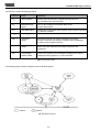
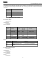
CRN/D encoder
as a subscriber in DeviceNet
CRN/D 10771 CE
Accompanying data sheet: CRN/D 10770
01 / 00
User Manual
TWK-ELEKTRONIK GmbH · D-40041 Düsseldorf · PB 10 50 63 · T. 02 11/63 20 67 · F. 02 11/63 77 05 · e-mail: [email protected] · http://www.twk.de
-1-
COPYRIGHT: The Operating Instructions TZY 10771
is owned by TWK-ELEKTRONIK GmbH and is
protected by copyright laws and international treaty provisions.
© 1999 by TWK-ELEKTRONIK GmbH
POB 10 50 63 n 40041 Düsseldorf n Germany
Tel. +49/211/63 20 67 n Fax +49/211/63 77 05
e-mail: [email protected] n internet: www.twk.de
-2-
0. Table of contents
Table of contents
1. Introduction ................................................................................................................ 5
2. Schematic circuit diagram: TWK encoder for DeviceNet ....................................... 6
3. Installation instructions ............................................................................................. 6
3.1 Encoder in plug-in version ................................................................................................................
3.2 Encoder with connecting cap ...........................................................................................................
3.2.1 Setting the subscriber address (MAC ID) ......................................................................................
3.2.2 Setting the baudrate ......................................................................................................................
3.2.3 Status LED ...................................................................................................................................
6
7
7
7
8
4. The encoder operating modes .................................................................................. 9
4.1 Polling mode ....................................................................................................................................
4.2 Bit strobed mode ..............................................................................................................................
4.3 Change-of-state mode ......................................................................................................................
4.4 Cyclical mode ..................................................................................................................................
9
9
9
9
5. Encoder parameters ................................................................................................ 10
5.1 Parameter description .................................................................................................................... 10
5.2 Encoder parameter values ............................................................................................................. 11
6. Encoder input data .................................................................................................. 11
7. Encoder status information .................................................................................... 12
8. The DeviceNet layer 7 protocol ............................................................................... 13
8.1 DeviceNet object structure .............................................................................................................
8.2 The encoder objects .......................................................................................................................
8.2.1 Identity Object ............................................................................................................................
8.2.2 Message Router Object ...............................................................................................................
8.2.3 DeviceNet Object ........................................................................................................................
8.2.4 Assembly Object ........................................................................................................................
8.2.5 Connection Object .......................................................................................................................
8.2.6 Position Sensor Objekt ................................................................................................................
8.3 DeviceNet connections ..................................................................................................................
8.4 The DeviceNet protocol ..................................................................................................................
8.5 Establishment of a connection to the encoder ................................................................................
8.6 Encoder parameterisation ...............................................................................................................
8.7 Request encoder input data ............................................................................................................
8.8 Request status information ............................................................................................................
8.9 Back parameter values up in EEPROM .........................................................................................
8.10 Set parameter values to default status .........................................................................................
13
13
15
15
16
16
17
18
19
20
20
21
22
22
23
23
9. DeviceNet Manager ................................................................................................. 24
9.1 Installation of EDS file ...................................................................................................................
9.2 Integration into the bus ...................................................................................................................
9.3 Parameterise encoder ....................................................................................................................
9.4 Integrate encoder into the scan list ................................................................................................
9.5 Go on-line and transfer data ...........................................................................................................
9.6 Set encoder address and baudrate in plug-in version ......................................................................
9.7 Store parameters in EEPROM .......................................................................................................
-3-
24
25
26
28
31
32
34
0. Table of contents
9.8 Load parameter default values ....................................................................................................... 34
9.9 Read out arbitrary attribute ............................................................................................................. 35
10. RS-Networx for DeviceNet .................................................................................... 36
10.1 Installation of EDS file .................................................................................................................
10.2 Integration into the bus .................................................................................................................
10.3 Parameterise encoder ...................................................................................................................
10.4 Integrate encoder into the scan list ..............................................................................................
10.5 Set encoder address and baudrate in plug-in version ....................................................................
10.6 Store parameters in EEPROM .....................................................................................................
10.7 Load parameter default values .....................................................................................................
10.8 Read out arbitrary attribute ...........................................................................................................
36
37
38
39
41
41
42
43
Appendix A: Literature ................................................................................................ 43
-4-
1. Introduction
1. Introduction
DeviceNet is a bus system which is based on CAN (Controller Area Network). The CAN bus, which was originally
developed by Robert Bosch GmbH, was developed especially for the automobile industry, and is currently used in many
premium segment passenger car models.
The stringent demands of the automobile industry have led to the following characteristic CAN bus features, which
also apply to DeviceNet:
- High transmission reliability (Hamming distance 6)
- Short response times
- Data format: max. 8 bytes
- Message-oriented bus system
- Availability of perfected and inexpensive system components
- Open concept and simplicity of expansion
While only layer 1 and layer 2 of the ISO/OSI communication model, are described via the CAN protocol, specified in
ISO/DIS standard 11898, DeviceNet additionally specifies both the transmission medium of layer 1 and the layer 7.
The following overview makes this clear once again:
ISO-Layer 7
Application Layer
ISO-Layer 2
Data Link Layer
(Protocol Layer)
DeviceNet-Spec.
CAN Protokoll
Specification
Physical Signaling
ISO-Layer 1
Transceiver
DeviceNet
Specification
Transmission Media
Fig 1.1 DeviceNet communication model
The availability of inexpensive ICs and the high inherent reliability of the CAN system, in particular, also make this bus
interesting for automation technology. The European organisation for the expansion of CAN in automation is the CiA CAN in automation (http://www.can-cia.de). This manufacturers’ and users’ organisation represents both the CANopen
protocol which has been developed in Germany, and the DeviceNet protocol, which is particularly favoured by the AllenBradley company, plus further derivatives.
However, the international DeviceNet manufacturers’ and users’ organisation is ODVA - Open DeviceNet Vendor Association
(http://www.odva.org), which is the publisher of the DeviceNet specifications |1|.
The specifications of layer 7 and the hardware section of layer 1 via DeviceNet result in the following characteristics:
- Set-up with trunk line and drop lines possible
- Up to 64 subscribers
- Subscribers can be disconnected from the bus without interrupting bus operation
- Data line and subscriber supply in one cable
- Data rates 125, 250, 500 kBaud (see Table 1.1)
Datarate
Max. length
Trunkline *
125K
250K
500K
500 m
250 m
100 m
Max. length
of a drop line
total
6m
6m
6m
156 m
78 m
39 m
Table 1.1 cable lengths
*
Values apply to the thick cable (DeviceNet thick cable), for the thin cable (DeviceNet thin cable) the maximum
length is always 100 m regardless of the data rate.
-5-
2. Schematic circuit diagram 3. Installation instructions
-Protection against wiring errors
-Support for subscribers which are supplied via the bus cable, and those equipped with a separate voltage supply
-Object-oriented application layer
-Support for communication between arbitrary subscribers and master/slave communication
-Discovery of duplicate node addresses
2. Schematic circuit diagram: TWK encoder for DeviceNet
Block Diagram
CAN DeviceNet
Photo
GaAlAs
Diodes transistors
CAN +
CAN Controller
µController-System
Multi-functional ASIC
PCA 82C251
CAN -
MWP
+ VS
- VS
Shield
Opto Analog
Array Asic
Fig. 2.1 CRN/D encoder schematic circuit diagram
Information regarding the actual position of the encoder is recorded via a multi-functional ASIC and an integrated
microprocessor (host controller). Communication between the host controller and CAN bus, including the implementation
of the communication protocol, is carried out via the SJA1000 CAN controller. This controller contains e.g. the priority of
access to the bus, which is defined via the message identifiers, error handling routines, arbitration loss routines in the
event of access to the bus, etc.
The interface between the CAN controller and the physical bus is implemented with CAN transceiver 82C251 in accordance
with CiA Standard ISO/DIS 11898. In accordance with the DeviceNet specifications, the supply voltage is equipped with
an MWP (Mis-Wiring Protection) - switch – and with an RC combination for screening purposes.
In the case of DeviceNet, the terminating resistor is never integrated into the subscriber, it must always be separately
connected at the end of the trunk line
3. Installation instructions
3.1 Encoder in plug-in version
The plug-in version of the encoder is equipped with a 5-pin micro or mini-design connector. (See pin assignment supplement
TY...). The address and baudrate are set via software (e.g. DeviceNet Manager from Allen-Bradley). (Also see Chapter 9.6
and Chapter 10.5)
The factory setting is:
Address 1
Baudrate 125 KB
Fig. 3.1 Encoder in plug-in version
-6-
3. Installation instructions
3.2 Encoder with connecting cap
The version with connecting cap is equipped with one PG threaded connection for bus-in and one for bus-out. Within the
connecting cap, the bus and the supply voltage which runs through the cable are wired to terminals. (See pin assignment
TY... enclosed with the cap).
In addition, the subscriber address (MAC-ID) and the baudrate are also set here.
The encoder is contacted with the cap via a 15-pin sub-D plug. In the event of an error, the encoder can be replaced
without any installation effort whatsoever. The connecting cap is disconnected from the encoder by unscrewing 2 fastening
screws.
Fig. 3.2 Encoder with connecting cap
3.2.1 Setting the subscriber address (MAC-ID)
The MAC-ID (Media Access Control Identifier) can be set via the dip switches in the range 0-63 in accordance with Table
3.1. The default value is 1.
Switch
6
5
5
Valency
4
4
3
3
2
2
1
1
Address
0
2
2
2
2
2
2
0
0
0
0
0
0
0
0
0
0
0
0
1
1
ON = 1
...
...
OFF = 0
...
...
1
1
1
1
1
1
63
Table 3.1 Setting the subscriber address (MAC-ID)
3.2.2 Setting the baudrate
Switch
8
7
Baudrate
0
0
125KB
ON = 1
0
1
250KB
OFF = 0
1
0
500KB
1
1
500KB
Table 3.2 Setting the baudrate
When setting the baudrate, please note the permissible cable lengths in Table 1.1 .
-7-
3. Installation instructions
3.2.3 Status LED
The connecting cap contains three LEDs, which provide information regarding the status of the encoder. This involves a
green LED for the supply voltage ( V ), and one green and one red LED (MNS), which together form the module/network
status LED defined in the DeviceNet specifications.
Status LED
Fixing screws
(unloosable)
PG9 cable glands
for “thin“ cable
Fig. 3.1 Connecting cap
MNS LED
Status
Explanation
Off
Not connected,
Not on-line
Device is not on-line:
- Dupl. MAC ID check not completed
- No voltage supply
Green
flashing
Device active and on-line,
no connections exist
The device is operating under normal conditions and
is on-line, no connection is established.
- Encoder has not yet been configured by master
- Configuration incomplete or faulty
Green
Device active and on-line,
connections exist
The device is operating under normal conditions and
is on-line, with connections „established“ state
- Encoder has been configured by master
Red
flashing
Minor error and/or
interruption of connection
Reparable error and/or one or more I/O
connections are in interrupted state
Red
Critical device error or
critical communication error
The device has an irreparable error,
it must be replaced.
The device has determined an error which makes
communication with the network impossible.
- Duplicate subscriber address (MAC-ID)
Red & green
flashing
Communication interrupted
A particular communication error. The device has
and receipt of a communication a network access error and is in communication
error enquiry code
error status
Table 3.3 LED status of the module/network status LED
-8-
4. The encoder operating modes
4. The encoder operating modes
The encoder operating modes determine the triggering of actual position value recording. The user can choose between
four different operating modes:
1. Polling mode
2. Bit strobed mode
3. Change-of-state mode
4. Cyclical mode
In addition, several operating modes can be set at the same time.
4.1 Polling mode
The standard operating mode in the master-slave system is the polling mode. In this case, the master interrogates all
subscribers cyclically. In this manner, all output data are transferred to the slaves, and all input data from the slaves are
read in one scan. The time between two scans can generally be set in the master.
The encoder therefore provides its input data when cyclically requested (poll command) by the master.
4.2 Bit strobed mode
If one wishes to address certain (or all) slaves at a certain point in time, the bit strobed mode is used.
If the encoder is operated in this mode, it transmits its input data as a reaction to the bit strobe command.
4.3 Change-of-state mode
If a subscriber is only intended to transfer its input values if these have changed, it is operated in change-of-state mode.
In this operating mode, a heartbeat rate can additionally be set. Following the expiry of an internal time, the subscriber
transmits new input data, even if these have not changed.
In this operating mode, the encoder provides its position data in the event of a change and following the expiry of the
heartbeat rate. The heartbeat rate can be set within the range 2 - 65535 ms in steps of 2 ms. (In this case, the AllenBradley DeviceNet Manager merely permits a minimum of 48 ms).
In this operating mode, a time delay can additionally be set within the range 2 - 65535 ms (production inhibit time). The
new actual position value is then only transferred to the master following the expiry of this time.
4.4 Cyclic mode
In cyclic mode, the subscriber provides its input data in a fixed temporal cycle. This send rate can be set in each
subscriber.
The cyclic mode is therefore a change-of-state mode which merely transmits the input data cyclically, and not in the
event of a change in values.
Strictly speaking, this is not a separate operating mode, but a variation of the change-of-state mode. For this reason, we
refer to change-of-state / cyclic mode.
-9-
5. Encoder parameters
5. Encoder parameters
The encoder can be adapted to customer-specific usages via its parameters. These can be written and read via separate
DeviceNet data traffic, so-called explicit messaging.
A Save command is available for storing the parameters in the encoder so that they are protected against power failure,
and a Restore command for loading the default values.
Attention: Following a Save or Restore command, the encoder provides no actual position value for approx. 300 ms.
These commands should therefore never be executed whilst the machine is in operation.
5.1 Parameter description
Parameter
Explanation
Code sequence
The code sequence specifies the direction of revolution in which the output code increases.
CW - Values increase on clockwise revolution
CCW - Values increase on counter clockwise revolution
Note: When looking towards the shaft
Scaling
Switches scaling on and off. The values for resolution, measuring range and preset
value are only effective when scaling is switched on.
Resolution
Resolution specifies the number of measuring units per revolution.
Measuring range
The measuring range specifies the total measuring range in measuring units; it is calculated
from: measuring range = number of distinguishable revolutions x resolution
Preset value
The preset value is the value which is displayed in the reference point. It may assume the
values 0 up to measuring range - 1.
Work area
low limit
Low limit of a work area which can be set by the user.
Work area
high limit
High limit of a work area which can be set by the user.
Table 5.1 Encoder parameters
Note: The measuring range must be selected so that the number of distinguishable revolutions is greater than or equal
to one. If the encoder is used in continuous mode, the number of distinguishable revolutions must be equal to 2n.
(with n=1,2,..,12)
- 10 -
5. Encoder parameters 6. Encoder input data
5.2 Encoder parameter values
Parameter
Range of values
Defaul value
Data type
Code sequence
CW/CCW
CW
BOOL
Scaling
Off/On
Off
BOOL
Resolution
1 - 8192
8192
UNSIGNED INTEGER
Measuring Range
1 - 33.554.432
33.554.432
UNSIGNED INTEGER
Preset Value
0 - (set measuring
range - 1)
0
UNSIGNED INTEGER
Work area low limit
0 - 33.554.432
1.048.575
UNSIGNED INTEGER
Work area high limit
0 - 33.554.432
32.505.856
UNSIGNED INTEGER
Table 5.2 Parameter
(The range of values shown, and the default values, apply in the case of 25 bit resolution)
Note: In the telegram, the data are always depicted in the form of low-byte before high-byte.
6. Encoder input data
As input data (from the point of view of the master) in I/O data traffic - I/O messaging - the encoder supplies the actual
position value and one status byte. The encoder’s operating mode determines the point in time at which actual value
recording is triggered. The encoder thereby supplies a total of five bytes of input data, which are to be interpreted as
follows:
Data field
Byte
1
2
3
4
5
Bit
7-0
15 - 8
23 - 16
31 - 24
39 - 32
Valency
2 7 - 20
215 - 28
223 - 216
231 - 224
0000XXXX
Meaning
Actual position value
Status byte
Table 6.1 Input data
0 = not used , X = used
Status byte:
Bit
7 6 5 4 3 2 1 0
Device Hardware Error
Hardware Memory Error
Communication Error
Device Specific Error (See chapter 7)
- 11 -
7. Encoder status information
7. Encoder status information
In addition to the I/O messaging input data, the encoder also provides further status information which, like the parameters,
can be read out via explicit messaging. Of course, the input data (Chapter 6) can also be read out via explicit messaging.
Designation
Data type
Explanation
Area
state register
Unsigned
short integer
Bit 0
Bit 1
Bit 2
Bit 3-7
: Not in use
: Equal to 1 with: position value > work area high limit
: Equal to 1 with: position value < work area low limit
: Not in use
Operating mode
Word
Bit 0
Bit 2
:
:
Max. single
turn resolution
Unsigned
integer
Specified in steps/revolution
Max. number of
dist. revolutions
Unsigned
integer
Specified in revolutions
Alarms
Word
Bit 0
Bit 1-11
Bit 12
Bit 13
Bit 14,15
Supported alarms
Word
Specifies which of the alarm messages listed in word
alarms are currently supported by the encoder
(All alarms are currently supported)
Warnings
Word
Bit 0-4
Bit 5
Bit 6-15
Supported
warnings
Word
Specifies which of the warning messages listed in the word
warnings are currently supported by the encoder
(All warnings are currently supported)
Profile and software
version
DWord
Word 0 = Profile version (Hex. depiction)
Word 1 = Software version (Hex. depiction)
:
:
:
:
:
0 = CW; 1 = CCW
0 = Scaling off; 1 = Scaling on
1 = Position Error
Not in use
1 = Eeprom Error
1 = CRC error
Not in use
: Not in use
: 1 = Actual position value not equal to preset value
: Not in use
Table 7.1 Status information
Note: In the telegram, the data are always depicted in the form of low-byte before high-byte.
- 12 -
8. The DeviceNet layer 7 protocol
8. The DeviceNet layer 7 protocol
Note: In order to commence the operation of the encoder on an Allen-Bradley SPS with the aid of the DeviceNet
Manager or RS-Networx, knowledge of this chapter is not absolutely mandatory. In this case, continue with Chapter 9
or Chapter 10.
8.1 DeviceNet object structure
In the case of DeviceNet, layer 7 of the ISO/OSI communication model is structured in a very object-oriented manner.
Each subscriber is comprised of a certain set of objects. Each object contains attributes (data) and services (functions)
of a very specific component of the subscriber. In turn, objects which represent the same system components are
comprised to form classes.
In a very abstract manner, the following Figure shows the DeviceNet structure from the object point of view:
MAC ID #1
MAC ID #2
MAC ID #4:Object Class #5:Instance #2:Attribute #1
DeviceNet Link
Object Class #7
Object Class #5
Attribute #1
Attribute #2
Instance #1
Instance #1
Instance #2
Instance #1
MAC ID #3
Object Class #5
MAC ID #4
Fig. 8.1 DeviceNet object structure
Each object which is filled with user data (instanced) is referred to as an instance. Several instances may therefore be
formed from one object.
All classes, instances, attributes and services are provided with identifiers (integer values). Together with the subscriber
address (MAC-ID), all attributes and services in the bus system can be uniquely addressed as a result of this. (Only the
address of an attribute is depicted in the above Figure.)
8.2 The encoder objects
The predefined master-slave connection set represents a simplification of the comprehensive options which DeviceNet
makes available. It represents a subset of DeviceNet, and provides all of the functions which are required in the case of
current, conventional master-slave relationships. Most significantly, the connection types (operating modes) are specified
in this case.
The predefined master-slave connection set also distinguishes between Group 2 Server/Client and Group 2 only
Server/Client, whereby the later is limited to those types of connection of significance for simple I/O subscribers,
thereby enabling the inexpensive implementation of DeviceNet slaves. For more detailed information, however, reference
must be made to the DeviceNet specifications |1| at this point. All of the following explanations refer to the implementation
of the encoder in DeviceNet.
The encoder represents a Group 2 only server.
- 13 -
8. The DeviceNet layer 7 protocol
The encoder contains the following objects:
Class ID
Class
Explanation
01hex
Identity Object
Contains general information regarding the slave such as,
e.g.: manufacturer ID, serial number...
02hex
Message Router
Object
Picks up all messages and forwards these to the
corresponding objects.
03hex
DeviceNet Object
04hex
Assembly Object
Contains the configuration and the status of the physical connection,
e.g.: MAC ID, baudrate
Permits the collection of attributes of various objects in one object.
05hex
Connection
Objekt
Administers both I/O and explicit messaging connections.
For each connection (e.g. polling, bit-strobe, explicit messaging)
an instance of this object is formed.
23hex
Position Sensor
Objekt
This object contains all encoder data. All of the encoder’s
Object input data, parameters and status information are
located here.
2bhex
Acknowledge
Handler Object
Monitors the reception of acknowledge messages in the case of
message-producing objects, e.g. COS connection
.
Table 8.1 Encoder objects
The following Figure shows the interfaces of the individual objects:
Fig. 8.2 Object interfaces
- 14 -
8. The DeviceNet layer 7 protocol
As can also be seen from this Figure, only one instance is created by each of these objects, with the exception of the
connection object. In the case of the connection object one instance is generated for each connection which is set-up,
e.g. poll mode or explicit message connection. In this case, the following instance IDs are allocated to the different
connections.
Connection
Instance ID #
Connection type
1
Explicit Messaging
2
Poll-Mode
3
Bit-Strobe-Mode
4
Change-of-State-Mode
Fig. 8.2 Instances of the connections
8.2.1 Identity Object
Class Code 01hex
Class Attributes
Not supported
Instance Attributes
Attr. Id
Attribute
Access
DeviceNet
Data type
Comment
1
Vendor ID
Read
UINT
TWK = 407
2
Device Type
Read
UINT
TWK = generic
3
Product Code
Read
UINT
0x01
4
Revision
Read
UINT
1.1
5
Status
Read
WORD
6
Serial Number
Read
UDINT
7
Product Name
Read
SHORT-STRING
Encoder CRN/D
Services
Service code
Service name
Comment
0Ehex
Get_Attribute_Single (read)
returns the value of an attribute
05hex
Reset
8.2.2 Message Router Object
Class Code 02hex
Class Attributes
Not supported
Instance Attributes
Not supported
Services
Not supported
- 15 -
8. The DeviceNet layer 7 protocol
8.2.3 DeviceNet Object
Class Code 03hex
Class Attributes
Attr. Id
Attribute
Access
DeviceNet
Data type
Comment
1
Revision
Read
UINT
Revision = 002
Instance Attributes
Attr. Id
Attribute
Access
DeviceNet
Data type
Remarks
1
MAC ID
Read/Write*
USINT
Revision = 002
2
Baud Rate
Read/Write*
USINT
Range 0-2
3
BOI
Read
BOOL
Value = 0
4
Bus-Off Counter
Read/Write
USINT
5
Allocation Information
Read
STRUCT of:
BYTE
USINT
Allocation Choice Byte
Master’s MAC ID
* only with plug-in version
Services
Service code
Service name
Comment
0Ehex
Get_Attribute_Single (Read)
Returns the value of an attribute
10hex
Set_Attribute_Single (Write)
Changes the value of an attribute
4Bhex
Allocate_Master/Slave_Connection_ Set
Predefined Master/Slave Connection Set
is requested
4Chex
Release_Group_2_Connection_Set
Connections of the Predefined Master/
Slave Connection Set are cancelled
8.2.4 Assembly Object
Class Code 04hex
Class Attributes
Not supported
Instance Attributes
Attr. Id
Attribute
Access
DeviceNet
Data type
3
Data
Read/Write
ARRAY
- 16 -
Remarks
8. The DeviceNet layer 7 protocol
Services
Service code
Service name
Comment
0Ehex
Get_Attribute_Single (read)
Returns the value of an attribute
10hex
Set_Attribute_Single (write)
Changes the value of an attribute
8.2.5 Connection Object
Class Code 05hex
Class Attributes
Not supported
Instance Attributes
Attr.Id Attribute
Access
DeviceNet
Data type
1
state
Read
USINT
2
instance_Type
Read
USINT
3
transportClass_trigger
Read
BYTE
4
produced_connection_id
Read
UINT
5
consumed_connection_id
Read
UINT
6
initial_comm_characteristics
Read
BYTE
7
produced_connection_size
Read
UINT
8
consumed_connection_size
Read
UINT
9
expected_packet_rate
Read/Write
UINT
12
watchdog_timeout_action
Read
USINT
13
produced_connection_path_length
Read
UINT
14
produced_connection_path
Read
Array
of UINT
15
consumed_connection_path_length
Read
UINT
16
consumed_connection_path
Read
Array
of UINT
17
production_inhibit_time
Read/
Write
UINT
Comment
By setting this value the status
of the connection is set to
”Established”, and all other
parameters are integrated
Services
Service code
Service name
Comment
0Ehex
Get_Attribute_Single (read)
Returns the value of an attribute
10hex
Set_Attribute_Single (write)
Changes the value of an attribute
- 17 -
8. The DeviceNet layer 7 protocol
8.2.6 Position Sensor Objekt
Class Code 23hex
Class Attributes
Attr. Id
Attribute
Access DeviceNet
Data type
1
Revision
read
UINT
2
Max. Instance
read
UINT
Remarks
Instance Attributes
ODVA specific Part:
Attr.Id
Attribute
Access
Data type Remarks
1
# of Attributes
read
USINT
Number of attributes of an instance
2
Attributes
read
Array of/
USINT
All attribute IDs present in an instance
3
Value
read
UDINT
Actual position of the sensor
11
Value Direction Control
read/
write
BOOL
0 = cw, 1 = ccw
39
Status Byte
read
USINT
Bit 0: 1=hardware error
Bit 1: 1=memory error
Bit 2: 1=communication error
Bit 3: 1=device specific error
Manufacturer specific Part:
112
Scaling
Read/
Write
BOOL
0=scaling disable;1=scaling enable
113
Measuring units per
revolution
Read/
Write
UDINT
Max. 8192 steps/U
114
Total measuring range
in measuring units
Read/
Write
UDINT
Max. 3554432 steps
115
Preset Value
Read/
Write
UDINT
Total measuring range - 1
128
Area state register
Read
USINT
Bit 1: 0=OK; 1=Max. limit exceeded
Bit 2: 0=OK; 1=Min. limit not achieved
129
Work area low limit
Read/
Write
UDINT
Default = 1048575 steps (for 25 Bit
resolution)
130
Work area high limit
Read/
Write
UDINT
Default = 32505856 steps (for 25 Bit
resolution)
144
Operating status
Read
WORD
Bit 0: 0=cw; 1=ccw
Bit 2: 0=scaling disable;1=scaling enable
145
Single Turn Resolution
Read
UINT
8192 steps/U (13 Bit)
146
Number of distinguishable revolutions
Read
UINT
4096 U (12 Bit)
147
Alarms
Read
WORD
Bit 12: 1 = Eeprom error
Bit 13: 1 = CRC error
Bit 14: 1 = XRAM error
148
Supported alarms
Read
WORD
All alarms are supported
149
Warnings
Read
WORD
Bit 5: 1=act. value n.e. to preset value
150
Supported warnings
Read
WORD
All warnings are supported
151
Profile and software
version
Offset Value
Read
DWORD
Read
UDINT
Wort 0 = Profil version
Wort 1 = Software version
Not supported
153
- 18 -
8. The DeviceNet layer 7 protocol
Services
Service code
Service name
Comment
0Ehex
Get_Attribute_Single (read)
Returns the value of an attribute
10hex
Set_Attribute_Single (write)
Changes the value of an attribute
15hex
Restore
Writes default values into EEPROM
16hex
Save
Writes non-volatile Attribute into EEPROM
8.3 DeviceNet connections
DeviceNet is a connection-based network. All communication takes place via connections (channels). Before communication
can take place, a connection must be set-up. In this case, the corresponding resources are provided and the identifiers
which this connection uses are specified.
As in the case of CAN, the identifier field is comprised of 11 bits. In DeviceNet, this available address space is divided
amongst the 4 areas Group1,Group2, Group3 and Group4 as follows:
IDENTIFIER BITS
10
9
8
6
7
4
5
Group 1
Message ID
0
3
2
1
0
Source MAC ID
Group 2
Message ID
1
0
1
1
Group 3
Message ID
1
1
1
1
1
1
1
1
1
1
1
1
X
X
X
X
10
9
8
7
6
5
4
3
2
1
0
MAC ID
Source MAC ID
Group 4 Message ID
(0 - 2f)
IDENTITY
USAGE
HEX
RANGE
000 - 3ff
Message Group 1
400 - 5ff
Message Group 2
600 - 7bf
Message Group 3
7c0 - 7ef
Message Group 4
7f0 - 7ff
Invalid CAN Identifiers
Table 8.3 DeviceNet Identifier
Only Group 1 and Group 2 messages are used in the predefined master-slave connection set. In this case, the message
IDs are already defined, and no longer have to be negotiated. The allocation of the message IDs to the connections is as
follows:
IDENTIFIER BITS
10
0
9
8 7 6
Group 1
Message ID
0
0
0
1
1
1
1
0
1
1
1
1
1
1
1
1
0
0
0
0
0
0
0
0
5
4
3
2
1
0
Source MAC ID
IDENTITY
USAGE
HEX
RANGE
Group 1 Messages
000 - 3ff
Source MAC ID
Slave' I/O Change of State or Cyclic Message
Source MAC ID
Slave's I/O Bit-Strobe Response Message
Source MAC ID
Slave's Poll Response or Change of State/Cyclic Acknow ledge
Group 2
MAC ID
Group 2 Message
Message ID
Source MAC ID
0 0 0 Master's I/O Bit-Strobe Command Message
Source MAC ID
0 0 1 Reserved for Master's Use - Use is TBD
Destination MAC ID
0 1 0 Master's Change of State or Cyclic Acknow ledge Message
Source MAC ID
0 1 1 Slave's Explicit/Unconnected Response Messages
Destination MAC ID
1 0 0 Master's Explicit Request Messages
Destination MAC ID
1 0 1 Master's I/O Poll Command/Change of State/Cyclic Message
Destination MAC ID
1 1 0 Group 2 Only Unconnected Explicit Request Messages (reserved)
Destination MAC ID
1 1 1 Duplicate MAC ID Check Message
1
1
1
0
1
1
1
0
1
Table 8.4 Predefined Master/Slave Connection Set Indentifier
- 19 -
400 - 5ff
8. The DeviceNet layer 7 protocol
8.4 The DeviceNet protocol
DeviceNet basically distinguishes between two types of protocol:
- Explicit messaging
- I/O messaging
Explicit messaging is used in order to specifically read or write attributes. In this case, a further distinction is made
between an unfragmented and a fragmented protocol.
I/O messaging is used for rapid I/O data traffic. In contrast to explicit messaging, the full eight data bytes of the CAN
telegram are available to the user in this case.
In the case of the encoder, the parameter data and the status information are read or written via explicit messaging, and
the five bytes of input data are read via I/O messaging.
8.5 Establishment of a connection to the encoder
Each connection to a slave is established via Group 2 only unconnected explicit request message (Group 2 message ID
6). In the predefined master-slave connection set, a connection object instance is formed via the service 4Bhex
Allocate_Master/Slave_Connection_Set of the DeviceNet object (see Table 8.2). In an Allocation Choice Byte, this
service is provided with the desired connection type (operating mode).
Allocation Choice Byte
7
6
Reserved Acknowledge
Suppression
5
4
3
2
1
0
Cycle
Change
of State
Reserved
Bit
Strobed
Polled
Explicit
Message
Beispiel: Allocation of the I/O-Connection Poll-Mode and Explicit Messaging
Master
MAC-ID = 0
Slave
MAC-ID = 1
Group 2 Message
Destination MAC-ID
Message-ID = 6 =
^Group 2 only Unconnected Explicit Request Message
Frag = 0, XID = 1, Source MAC-ID = 0
Service = Req. Allocate_Master/Slave_Connection_Set
Class-ID = DeviceNet Object
Instanz-ID = 1
Allocation Choice = Polled + Explicit Message
Allocator’s MAC-ID = 0
Identifier = 10 000001 110, Data = 00 4B 03 01 03 00
Group 2 Message
Source MAC-ID
Message-ID = 3 =
^Slaves Explicit/Unconnected Response Message
Frag=0, XID = 1, Destination MAC-ID=0
Service = Resp. Allocate_Master/lave_Connection_Set
Message Body Format = DeviceNet(8/8)
Identifier = 10 000001 011, Data = 00 CB 00
As a result of the previous example, an instance is generated with ID1 (explicit messaging connection) and ID 2 (I/O
messaging poll mode) of the connection object. These connections which are created are subsequently in the „Configuring“
status (instance attribute 1 = 1). In order to transfer them to the „Established“ status (instance attribute 1 = 3), the
Expected_Packet_Rate (instance attribute 9) must be set. This is shown as an example for the poll mode instance in the
following.
- 20 -
8. The DeviceNet layer 7 protocol
Example: Set the Expected_Packet_Rate attribute
Setting an instance attribute is carried out identically for all objects with the service 10hex Set_Attribute_Single. In this
case, for example, a time of 1s is set.
Master
MAC-ID = 0
Slave
MAC-ID = 1
Group 2 Message
Destination MAC-ID
Message-ID
Frag = 0, XID = 1, Source MAC-ID = 1
Service = Request Set_Attribute_Single
Class-ID = Connection Object
Instanz-ID = 2
Attribute-ID = Expected_Packet_Rate
Time in ms
Identifier = 10 000001 100, Data = 41 10 05 02 09 E803
Group 2 Message
Source MAC-ID
Message-ID
Frag = 0, XID = 1, Destination MAC-ID = 0
Service = Response Set_Attribute_Single
Time set in ms
Identifier = 10 000001 011, Data = 00 90 E803
8.6 Encoder parameterisation
Encoder parameterisation is carried out, in the same manner as setting the Expected_Packet_Rate, with an explicit
message and the 10hex Set_Attribute_Single service of the position sensor object.
Example: Setting the code direction (attribute bhex) to 01hex
Master
MAC-ID = 0
Slave
MAC-ID = 1
Group 2 Message
Destination MAC-ID
Message-ID
Frag = 0, XID = 1, Source MAC-ID = 1
Service = Request Set_Attribute_Single
Class-ID = Position Sensor Object
Instanz-ID = 1
Attribute-ID = Value Direction Control
Value = ccw
Identifier = 10 000001 100, Data = 00 10 23 01 0b 01
Group 2 Message
Source MAC-ID
Message-ID
Frag = 0, XID = 1, Destination MAC-ID = 0
Service = Response Set_Attribute_Single
Identifier = 10 000001 011, Data = 00 90
- 21 -
8. The DeviceNet layer 7 protocol
8.7 Request encoder input data
The actual data are requested via I/O messaging. Depending on which connection is set-up, another message ID may
have to be used for the request.
In the case of polling, each subscriber is individually addressed with a poll command. Subscribers which output data also
receive the output data with the poll command. These do not exist in the case of the encoder.
Example: Reading actual values in Poll-Mode
Master
MAC-ID = 0
Slave
MAC-ID = 1
Group 2 Message
Destination MAC-ID
Message-ID
Identifier = 10 000001 101, Data = not present
Group 1 Message
Message-ID
Source MAC-ID
Actual position value
Status byte
Identifier = 0 1111 000001, Data = 56341200 00
8.8 Request status information
The encoder status information, which exists in addition to the status byte of the input data must be read out via explicit
messaging. In the case of all objects, the object attributes are read with the 0Ehex Get_Attribute_Single service.
Example: Reading Attribute 80hex Area State Register
Master
MAC-ID = 0
Slave
MAC-ID = 1
Group 2 Message
Destination MAC-ID
Message-ID
Frag = 0, XID = 1, Source MAC-ID = 0
Service = Request Get_Attribute_Single
Class-ID = Position Sensor Object
Instanz-ID = 1
Attribute-ID = Area State Register
Identifier = 10 000001 100, Data = 00 0E 23 0180
Group 2 Message
Source MAC-ID
Message-ID
Frag = 0, XID = 1, Destination MAC-ID = 0
Service = Response Get_Attribute_Single
Actual value Area State Registers
Identifier = 10 000001 011, Data = 00 8E 04
- 22 -
8. The DeviceNet layer 7 protocol
8.9 Back parameter values up in EEPROM
With the aid of service 16hex „Save“ of the position sensor object, all parameter values are stored in the encoder’s
EEPROM, where they are protected against power failure.
Example:
Master
MAC-ID = 0
Slave
MAC-ID = 1
Group 2 Message
Destination MAC-ID
Message-ID
Frag = 0, XID = 1, Source MAC-ID = 0
Service = Request Save
Class-ID = Position Sensor Object
Instanz-ID = 1
Identifier = 10 000001 100, Data = 00 16 23 01
Group 2 Message
Source MAC-ID
Message-ID
Frag = 0, XID = 1, Destination MAC-ID = 0
Service = Response Save
Identifier = 10 000001 011, Data = 00 96
8.10 Set parameter values to default status
Service 15hex „Restore“ loads all parameter variables together with their default values, and subsequently stores these
in EEPROM. The default values only become effective after restarting the encoder (Power off/on).
Example:
Master
MAC-ID = 0
Slave
MAC-ID = 1
Group 2 Message
Destination MAC-ID
Message-ID
Frag = 0, XID = 1, Source MAC-ID=0
Service = Request Restore
Class-ID = Position Sensor Object
Instanz-ID = 1
Identifier = 10 000001 100, Data = 00 15 23 01
Group 2 Message
Source MAC-ID
Message-ID
Frag = 0, XID = 1, Destination MAC-ID = 0
Service = Response Restore
Identifier = 10 000001 011, Data = 00 95
- 23 -
9. DeviceNet-Manager
9. DeviceNet Manager
This Chapter describes the integration of the TWK CRN/D encoder into the DeviceNet master-slave system of an AllenBradley SPS on the basis of the DeviceNet Manager from Allen-Bradley (Rockwell). An exact knowledge of the objects,
as is described in Chapter 8, is not necessary for this.
Planning the DeviceNet system with the DeviceNet Manager |2| is possible in several ways. In this case, a distinction is
principally made between off-line and on-line configuration.
In the case of off-line configuration, the bus structure can be planned without the existence of a connection to the bus,
and the subscribers can be parameterised. The connection is subsequently established, and the user data are transferred
to the master and the subscribers.
In the case of on-line configuration, the bus structure is read in via an existing connection, and the subscribers are
parameterised on-line.
The procedure for off-line configuration is described in the following.
9.1 Installation of EDS file
As a result of an error in the DeviceNet Manager, the diskette contains two EDS files:
- 1.EDS:
- DNetMan.EDS:
Standard EDS file according to specifications (Use this EDS file for programs such as RSNetworx and others)
Use this EDS file for the DeviceNet Manager only
In order to install the EDS file, select the Install EDS Files... menu item in the main menu under Utilities. In the following
window, select the DNetMan.eds file.
Fig. 9.1 Installation of EDS-file
You are then asked whether you wish to allocate a bitmap to the new device. Please respond with yes in this case. The
following Figure displays the dialog in which you may now select the crn_d_m (plug-in version) or crn_d_z (connecting
cap version) bitmap which has been provided on the diskette.
- 24 -
9. DeviceNet-Manager
Fig. 9.2 Installation of encoder symbol
The installation of the EDS file and the subscriber symbol is now complete.
9.2 Integration into the bus
After you have created a project, you may now select the Encoder CRN/D from the Device List under Generic, TWK
Elektronik GmbH, and integrate this into the bus via drag & drop.
Fig. 9.3 Encoder installation
You are subsequently requested to input a subscriber name and the node address. Please specify the address set for the
encoder as the node address (can be set via dip-switch in the connecting cap version, can be set via software in the plugin version (See Chapter 9.6)).
- 25 -
9. DeviceNet-Manager
Fig. 9.4 Edit node address
In this case, the encoder default address 1 has been retained, and the proposed name, „Node_1“ has been accepted as
the name of the node. After accepting with OK, the encoder appears in the bus.
Fig. 9.5 Encoder in the DeviceNet
9.3 Parameterise encoder
In order to change the parameters of a subscriber in DeviceNet, two different options are available in the DeviceNet
Manager:
- Basic Device Configuration
- Enhanced Device Configuration
The Basic Device Configuration is only available in on-line mode. In this case, the location of the parameter (attribute)
in the object model of the DeviceNet software and the function (service) with which this parameter can be accessed must
be known.
- 26 -
9. DeviceNet-Manager
Enhance Device Configuration represents a comfortable option for changing and reading out the encoder’s parameters.
This is possible both on-line and off-line (in file only). The parameters can be stored in a file (*.dcf) in enhanced mode, in
order to enable these to be transferred to the subscriber at a later point in time.
A Save command is available, in order to store the parameters in the encoder’s EEPROM so that they are protected
against power failure. In addition, the default values of all parameters can be re-loaded again with the Restore command.
The Save and Restore commands can only be executed via the Basic Device Configurator. (Chapter 9.7 and 9.8)
Now call the Enhanced Configurator up by double-clicking onto the encoder symbol. In off-line mode, the default values
of the EDS file are used as parameter defaults. The following window is displayed:
Fig. 9.6 Encoder parameters
The values which are identified with an „R“ following the number represent the encoder status information; these can only
be read. All other values are parameters which can be edited. The values can be changed by double-clicking onto the
parameter or via the Modify Parameter button. Depending on whether this involves a numerical or a boolean parameter,
one of the following windows is displayed:
Boolean parameter:
If you wish to change the encoder’s resolution or total measuring range, you must change parameter #4 „Scaling“ to „ON“.
Fig. 9.7 Edit boolean parameter
- 27 -
9. DeviceNet-Manager
Numerical parameter:
Numerical values are changed via the following dialog. The value can be changed either via a numerical input or via the
sliding controller. In this case, for example, a resolution of 4096 measuring units/revolutions is set.
Fig. 9.8 Edit numerical parameter
After setting all parameters, these can be stored in a file via the enhanced configurator’s Save to File... button. In this
case, a separate file is generated for each subscriber (Node_1.dcf in this case).
9.4 Integrate encoder into the scan list
In order to specify the encoder’s operating mode and to allocate it to a master, it must be integrated into a master’s scan
list.
The following Figure shows the structure of a bus with an Allen-Bradley SPS SLC500 with master 1747-SDN scanner
module. All of the following Figures refer to this configuration.
Fig. 9.9 Bus set-up with master
- 28 -
9. DeviceNet-Manager
By double-clicking onto the SPS symbol, the following dialog for setting the master parameters is accessed. For the
application in the example, the settings can be integrated and stored in a file (in this case: Node_0.sm4).
Fig. 9.10 Parameterise Master
On actuation of the Edit Scan List... button, the Scan List Editor appears. As no subscriber has been added to the scan
list as yet, an empty window is displayed.
Fig. 9.11 Scanlist of the master
- 29 -
9. DeviceNet-Manager
In order to add subscribers to the scan list, now actuate the Proj... button in the Add Devices From group field. This
causes the bus structure to be overlayed again:
Fig. 9.12 Add encoder to scan list
Now drag the encoder onto the master symbol via drag & drop. The encoder is provided with a red frame and the number
0. This shows that the subscriber has been allocated to the scan list of the master whose ID is 0. The window can then
be closed with OK.
The encoder now appears in its default operating mode, poll mode, in the Scan List Editor.
Fig. 9.13 Scanlist with encoder
- 30 -
9. DeviceNet-Manager
If you wish to change the operating mode of the encoder, double-click onto line 1. You then access the following window,
in which you may choose between the operating modes poll mode, bit-strobe mode and change-of-state / cyclic mode.
Several operating modes may be selected at the same time. The number of input data (Rx) must always be five bytes,
and the number of output data zero bytes.
Fig. 9.14 Specify encoder operating mode
The encoder has now been integrated into the master’s scan list with the desired operating mode. So that you may
access the data in the SPS, the scanner still has to be provided with information regarding the location of the encoder’s
data in the input domain of the SPS. The Datatable Map exists for this purpose. This may either be edited manually, or
automatic mapping can be carried out. For the application in the example, automatic execution and the acceptance of the
standard settings are sufficient.
Now save the settings which have been carried out in a file (in this case: Node_0.sl4).
9.5 Go on-line and transfer data
After the encoder parameters, the master settings and the scan list have been stored in one file, these are transferred to
the subscribers in the following.
Transfer scan list to the master: Establish the on-line connection to your network, switch to the Scan List Editor and
load the scan list created in Chapter 9.4. You should now see the following Figure:
Fig. 9.15 Transfer scan list to the master
- 31 -
9. DeviceNet-Manager
Now transfer the scan list to the scanner (master) with Save to SDN. In the case of a new project, specify All Records in
the following selection window.
Transfer parameters to the encoder:
By double-clicking onto the encoder symbol, open the Device Configurator - Enhanced Mode. As an on-line connection
exists, the parameters which currently exist in the encoder are now read out and displayed.
Load your parameter values, which you stored under Chapter 9.3, from the Node_1.dcf file. The following Figure, for
example, is displayed:
Fig. 9.16 Transmit parameters to the encoder
Then transfer your parameters to the encoder with the Save to Device button. The new values are stored in the encoder’s
RAM, where they immediately become valid. So that these remain valid in the encoder even following a power failure,
they can be stored in the encoder’s EEPROM, where they are protected against power failure, with a separate command.
(See Chapter 9.7)
9.6 Set encoder address and baudrate in plug-in version
The plug-in version of the CRN/D allows the subscriber address (MAC ID) and the baudrate (125 kB, 250KB, 500KB) to
be set via software.
The baudrate should always be set in a point-to-point connection to the subscriber, as changing the baudrate of a
subscriber in the network can lead to the failure of the entire bus. In contrast, the subscriber address may be changed
even whilst the bus is in operation. Care must, however, be taken that the address of an existing subscriber is not used.
A baudrate change only takes effect after the voltage has been switched off/on again, the address is changed directly.
Now establish a point-to-point connection with the encoder, and go on-line with the DeviceNet Manager. Close any project
which may be open, and select the Node Commissioning item under Utilities.
- 32 -
9. DeviceNet-Manager
Change the subscriber address:
In the left-hand Node Address field, specify the current address of the encoder (default address is 1) and in the right-hand
field, the desired new address. The new address becomes valid in the encoder after actuating Apply Node Settings.
Fig. 9.17 Set node address
Change the baudrate:
The current baudrate (in this case 125 KB) is displayed in the Current Device Settings field. Specify the desired new
baudrate under New Device Settings. After actuating Apply Node Settings, a further warning, that this setting is only to
be changed in a point-to-point connection, is issued. Following confirmation, the new baudrate is stored in the encoder,
but only takes effect after the voltage has been switched off/on.
Of course, both changes can also be carried out at the same time. The additional storage of the subscriber address and
the baudrate is not necessary.
Fig. 9.18 Set baudrate
- 33 -
9. DeviceNet-Manager
9.7 Store parameters in EEPROM
Power failure-safe storage of the parameters in EEPROM is carried out via the Device Configurator - Basic Mode.
In the existing on-line connection, switch to the Basic Device Configuration menu via the main menu item Utilities.
Specify the encoder’s subscriber address, and select the service 22dec. from class 35dec (Position Sensor Object).
Subsequently actuate the Save to Device button. (See Figure 9.19)
The successful storage of the parameters is displayed in the DeviceNet Manager’s status line.
Fig. 9.19 Store parameters in EEPROM
9.8 Load parameter default values
All encoder parameter default values can be restored with the command „Restore“ service code 21dec of the position
sensor object.
In the existing on-line connection, switch to the Basic Device Configuration menu via the main menu item Utilities.
Specify the encoder’s subscriber address, and select the service 21dec. from class 35dec (Position Sensor Object).
Subsequently actuate the Save to Device button.
The default values become effective following Power off/on.
Fig. 9.20 Load parameter default values
- 34 -
9. DeviceNet-Manager
9.9 Read out arbitrary attribute
All attributes, which are identified as being legible, of the various DeviceNet objects which are present in the encoder can
be read via the Basic Configurator. The list of all objects and the services which these contain can be found in Chapter 8
The reading out of all attributes is generally carried out with the Get Attribute service (Service ID 14dec), setting with the
Set Attribute service (Service ID 16dec).
As an example, the serial number (attribute 6 of the identity object) will be read in this case.
To achieve this, switch to the menu Basic Device Configuration... via the main menu item Utilities in the existing on-line
connection. Specify the encoder’s subscriber address, and select class 1 (Identity object), instance 1, attribute 6. Change
the depiction (Data Radix) to hex and the data size to double word. The necessary service 16dec is the default setting.
Subsequently actuate the Load from Device button.
Fig. 9.21 Read serial number
- 35 -
10. RS-Networx for DeviceNet
10. RS-Networx for DeviceNet
This Chapter describes the integration of the TWK CRN/D encoder into the DeviceNet master-slave system of an AllenBradley SPS on the basis of the planning tool, RS-Networx for DeviceNet. An exact knowledge of the objects, as
described in Chapter 8, is not necessary for this.
10.1 Installation of EDS file
As a result of an error in the DeviceNet Manager, the diskette contains two EDS files:
- 1.EDS:
- DNetMan.EDS:
Standard EDS file according to specifications (Use this EDS file for programs such as
RS-Networx and others)
Use this EDS file for the DeviceNet Manager only
In order to install the EDS file, select the EDS Wizard... menu item in the main menu under Tools. You are thereupon
guided through several dialogs for installing the EDS file and the encoder symbol. In this case, enter A:\1.EDS as the file
name in the following dialog.
Fig. 10.1 Installation of EDS-file
The encoder symbol which is also provided on the diskette can subsequently be selected:
- crn_d_m.ico
- crn_d_z.ico
for the plug-in version
for the version with connecting cap
Fig. 10.2 Installation of encoder symbol
- 36 -
10. RS-Networx for DeviceNet
10.2 Integration into the bus
Following the installation of the EDS file, the encoder appears in the hardware catalogue under Generic Device / Encoder
CRN/D. It can now be integrated into the bus via drag & drop.
Fig. 10.3 Encoder integration
When the encoder is integrated, it is automatically allocated with the next free address. In order to change the address
and set the encoder parameters, double-click onto the encoder symbol contained in the bus. The following window, in
which the address set in the encoder must be set under the register General / Address, appears. In this case, encoder
default address 1 has been entered.
Fig. 10.4 Allocate subscriber address
- 37 -
10. RS-Networx for DeviceNet
10.3 Parameterise encoder
The following window is accessed via the Device Parameters register (See Fig. 10.4) :
Fig. 10.5 Parameterise encoder
All of the encoder’s parameters and status information are displayed here (The values of a 25-bit encoder are shown). The
display can be reduced to parameters only or status information only via the Groups field.
Following the integration of the encoder into the bus and without an on-line connection to the bus, the default values of
the parameters and status information from the EDS file are displayed here. By double-clicking onto a parameter this can
be changed. Status information can only be read and is identified with a small lock. Using the Restore Default Values
button, the default values can be read out from the EDS file again at any time.
A help text can be called up for each parameter via the Parameter Help button.
If an on-line connection exists, the parameters and status information can also be read out from the encoder here (Upload
From Device) or the parameters can be transferred to the encoder (Download To Device). In this case, the values can also
be cyclically updated via the Start Monitor button.
A Save command is available for storing the parameters in the encoder’s EEPROM, where they are protected against
power failure. In addition, the default values of all parameters can be reloaded again with the Restore command. The
Save and Restore commands can only be executed via the „Class Instance Editor“ (See Chapter 10.6 and Chapter 10.7).
The EDS I/O Default register merely displays the number of bytes which the encoder transmits or receives in the various
operating modes. The operating mode can only be set in the master’s scan list (Chapter 10.4).
Now change the parameters according to your requirements, and exit the window with OK. The separate transmission of
the parameters to the encoder is not necessary. In the case of RS-Networx, the entire bus planning can be transferred
with one command.
- 38 -
10. RS-Networx for DeviceNet
10.4 Integrate encoder into the scan list
In order to specify the operating mode of the encoder and to allocate it to a master, it must be integrated into the scan list
of a master.
The following Figure shows a bus set-up with the 1747-SDN master of an Allen-Bradley SPS SLC500. All of the following
figures refer to this configuration.
Fig. 10.6 Bus set-up with master
The master’s settings are accessed by double-clicking onto the scanner symbol. If you then access the Scanlist register,
you are provided, in the left-hand section, with a selection of the devices contained in the bus. Mark the encoder and
transfer it to the right-hand window with the aid of the arrow key.
Fig. 10.7 Scan list
- 39 -
10. RS-Networx for DeviceNet
If you wish to change the operating mode of the encoder, actuate the Edit I/O Parameters button. This provides you with
access to the following window, in which a selection may be made between the poll mode, bit-strobe mode and changeof-state / cyclic mode operating modes. Several operating modes may also be selected at the same time. Five bytes
must always be specified as the number of input data (Rx-Size), and zero bytes for the output data (Tx-Size).
Fig. 10.8 Specify encoder operating mode
The encoder has now been integrated into the master’s scan list with the desired operating mode. So that the data can be
accessed in the SPS, the scanner must now be provided with information regarding the location of the encoder’s data in
the input domain of the SPS. This is carried out via mapping. Mapping can be carried out either manually or automatically.
As a result of integration into the scan list with Automap On Add switched on (See Fig. 10.7), automatic mapping has
already been carried out. The encoder should now be seen in the Input register as shown below (polling mode only in this
case) .
Fig. 10.9 Mapping
- 40 -
10. RS-Networx for DeviceNet
Now exit the window with O.K., store your planning and go on-line. After RS-Networx has read the bus set-up in, select
Download to Network under Network in the main menu, in order to transfer the entire bus set-up to the scanner .
10.5 Set encoder address and baudrate in plug-in version
The plug-in version of the CRN/D allows the subscriber address (MAC ID) and the baudrate (125 kB, 250KB, 500KB) to
be set via software.
The baudrate should always be set in a point-to-point connection to the subscriber, as changing the baudrate of a
subscriber in the network can lead to the failure of the entire bus. In contrast, the subscriber address may be changed
even whilst the bus is in operation. Care must, however, be taken that the address of an existing subscriber is not used.
A baudrate change only takes effect after the power has been switched off/on again, the address is changed directly.
Now establish a point-to-point connection with your plug-in version encoder, and select Node Commissioning under Tools
in RS-Networx. The encoder which is to be changed can be selected under Browse in the window which now appears. The
Current Device Settings are then displayed. The new values for the baudrate and the subscriber address can be specified
under New Device Settings. This may, for example, then appear as follows:
Fig. 10.10 Set subscriber address and baudrate
If you now depress the Apply button, the address and the baudrate are changed in succession, and the new values are
subsequently displayed under Current Device Settings.
10.6 Store parameters in EEPROM
Storage of the parameters in EEPROM, where they are protected against power failure, is carried out via the „Class
Instance Editor“.
Mark the encoder in the bus and switch, in the case of an existing on-line connection, to the Instance Editor menu via the
Device main menu item. Under Data Address, specify Class 0x23 (Position Sensor Object), and select the Save (0x16)
service under service code. Then actuate the Send button. (See Figure 10.11)
The successful storage of the parameters is displayed in the status line.
- 41 -
10. RS-Networx for DeviceNet
Fig. 10.11 Store parameters in EEPROM
10.7 Load parameter default values
All encoder parameter default values can be restored with the command „Restore“ service code 21dec of the position
sensor object.
Mark the encoder in the bus and switch, in the case of an existing on-line connection, to the Class Instance Editor submenu via the Device main menu item. Under Data Address, specify Class 0x23 (Position Sensor Object), and select the
Restore (0x15) service. Then actuate the Send button.
The default values take effect after switching the power off/on.
Fig. 10.12 Load parameter default values
- 42 -
10. RS-Networx for DeviceNet
10.8 Read out arbitrary attribute
All attributes, which are identified as being legible, of the various DeviceNet objects which are present in the encoder can
be read via the „Class Instance Editor“. The list of all objects and the services which these contain can be found in
Chapter 8 .
The reading out of all attributes is generally carried out with the Get Attribute service (Service ID 0xE), setting with the
Set Attribute service (Service ID 0x10).
As an example, the serial number (attribute 6 of the identity object) will be read in this case.
Mark the encoder in the bus and switch, in the case of an existing on-line connection, to the Class Instance Editor submenu via the Device main menu item. Under Data Address, specify Class 0x1 (Identity Object), Attribute 0x6 (serial
number), and select the Service Get Single Attribute (0xE) service under Service code. Under Received Data, change
Size into double and Radix into hexadecimal. Then actuate the Send button. The serial number then appears in the output
window.
Fig. 10.13 Read out serial number
Appendix A: Literature
|1| ODVA - Open DeviceNet Vendor Association DeviceNet Specifications Release 2.0
|2| DeviceNet Manager Software user Manual 1787 - MGR
- 43 -