1
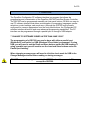
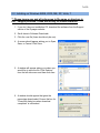
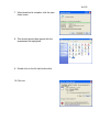
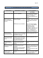
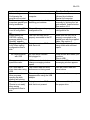
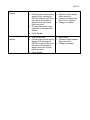
GSC300
CONFIGURATOR
SOFTWARE
INTERFACE
Installation and User Manual for the
GSC300 Configurator PC Software Interface
File: MAN-0040R2.40, GSC300 Configurator User Manual.doc
May 2011
READ MANUAL BEFORE USING PROGRAMMER
2 of 30
Thank You For Purchasing This DynaGen Product
Please Read Manual Before Using Programmer
Receipt of Shipment and Warranty Return Information
Upon receipt of shipment, carefully remove the unit from the shipping container and
thoroughly examine the unit for shipping damage. In case of damage, immediately
contact the carrier and request that an inspection report be filed prior to contacting
DynaGen.
All returned items are to be shipped prepaid and include a Return Material Authorization
(RMA) number issued by DynaGen.
Limited Warranty
For warranty information refer to the standard terms and conditions of sale at
www.dynagen.ca.
Dynagen GSC300 Webpage
For up-to-date software and other information please see the GSC300 section of the
Dynagen website at: www.dynagen.ca/products/GSC300.htm.
3 of 30
END-USER AGREEMENT FOR GSC300 Configurator PC Software
GRANT OF RIGHTS
DynaGen Technologies grants you the following non-exclusive rights:
You may install and use the enclosed software product on your computer for reading
and configuration of the GSC300 engine controller.
You may not reverse- engineer, decompile, or disassemble the software product, except
and only to the extent that applicable law notwithstanding this limitation expressly
permits such activity.
You may not rent or lease the software product.
LIMITATION OF LIABILITY
NO LIABILITY FOR CONSEQUENTIAL DAMAGES. To the maximum extent permitted
by applicable law, in no event shall DynaGen Technologies or its suppliers be liable for
any damages whatsoever (including, without limitation, damages for loss of business
profit, business interruption, loss of business information, or any other pecuniary loss)
arising out of the use of, or inability to use this software product.
.
4 of 30
Table of Contents
1.
2.
Welcome .................................................................................................................. 5
Installing the GSC300 Software ............................................................................... 6
2.1
Before you begin............................................................................................... 6
2.2
Software / Hardware Requirements .................................................................. 6
2.3
Installing on Windows 98SE, 2000, ME, XP, Vista, 7........................................ 7
2.4
Installing USB Driver for use with Dynagen GSC300 USB interface............... 15
2.4.1
For Windows XP ...................................................................................... 15
2.4.2
For Windows Vista or 7............................................................................ 17
3. Using the GSC300 Programmer ............................................................................ 19
3.1
Connecting the GSC300 to your PC ............................................................... 19
3.2
Starting the Configurator program................................................................... 20
3.3
GSC300 Configuration .................................................................................... 21
3.3.1
Load a Default Configuration File ............................................................ 21
3.3.2
Load a User Defined Configuration File ................................................... 21
3.3.3
Manually entering Configuration settings ................................................. 22
3.3.4
Storing Settings to the GSC300............................................................... 22
3.3.5
Reading data from the GSC300............................................................... 22
3.3.6
Saving a configuration to disk .................................................................. 23
3.3.7
Set Port Address...................................................................................... 23
3.3.8
Customize Display Messages.................................................................. 23
3.3.9
Setting Senders For Input Failures. ......................................................... 24
4. Configurable Features of the GSC300 ................................................................... 26
5. TROUBLESHOOTING GUIDELINES .................................................................... 28
5 of 30
1. Welcome
The DynaGen Configurator PC software interface is a program that allows the
programming and customization of the DynaGen GSC300 AutoStart Engine Controller.
The GSC300 can be programmed manually via front panel buttons OR with our easy-touse PC software interface that allows customization of messaging; languages; sender
selections; control settings; and much more. Although the GSC300 may be easily
configured for common parameters from the front panel buttons, the Configurator PC
software interface allows full and more advanced programming capabilities. The PC
interface can be programmed through a parallel port or through a USB adaptor.
** CHANGE TO SOFTWARE ISSUED LATER THAN JUNE 15/08**
The programming of a GSC300 can now be done with either a parallel port
(Windows XP and earlier) or USB (Windows XP and latter) programmer. If using
USB, you will need to use the Read and Store buttons under the USB heading. If
using a parallel port you will need to use the Load and Store buttons under the
Parallel port heading.
When changing messages you will need to click the check mark for USB in the
Change Message window before reading or storing messages.
DO NOT connect the programmer into the GSC300 when it is powered. This may
corrupt the GSC300.
6 of 30
2. Installing the GSC300 Software
2.1 Before you begin
In order to install and use the DynaGen software, you should have a basic
understanding of how to use your computer. If you do not, we recommend that you ask
someone who does to help you, or that you read the user manual that came with your
computer.
If you encounter any problems or errors while installing the DynaGen Configurator
software, please refer to Troubleshooting Guidelines on page 28.
2.2 Software / Hardware Requirements
For the DynaGen Configurator software to work reliably and efficiently, your computer
must meet or exceed the minimum requirements specified in the following table.
The GSC300 parallel port programmer is not supported on Windows Vista or
latter operating systems. You must use the GSC300 USB programmer.
The GSC300 USB programmer is not supported on operating systems below
Windows XP.
Operating System
Processor
Memory
Hard Drive
Video card display
Peripherals
Port
Windows 98SE*, 2000*,
ME*, XP, Vista*, 7*
* see boxes above
Pentium or equivalent
processor
Minimum 64 MB RAM
Minimum 20 MB Free
Disk Space
Minimum 256 colors at
1024x768
CD-ROM Drive
ECP Printer Port
7 of 30
2.3 Installing on Windows 98SE, 2000, ME, XP, Vista, 7
** Please ignore any and all references to file name or structure in
the** images provided. These are strictly for visual reference
1. If you don’t have an installation CD, download the software from the Support
section of the Dynagen website.
2. Scroll down to Software Downloads.
3. Click the .exe file (there should only be one).
4. A screen should appear asking you to Open,
Save, or Cancel. Click Save.
5. A window will appear asking you where you
would like to save the file. Click Desktop
from the left side menu and then click save.
6. A window should appear that gives the
percentage downloaded. Ensure the box for
“Close this dialog box when download
completes” is unchecked.
8 of 30
7. When download is complete, click the open
folder button.
8. This window should then appear with the
downloaded file highlighted.
9. Double click on the file (left double click).
10. Click run.
9 of 30
11. Click next.
12. Read the instructions presented in the
window before clicking next.
a. If using USB programmer make
sure it is not plugged in.
b. During the installation a popup
window will ask you to restart
windows. Click the “Cancel”
button.
c. Uninstall any older GSC300 PC
Interfaces by going into the start
menu and clicking uninstall.
d. Ensure the Windows Program Folder is not read only. This is usually a
concern only for large companies. Contact your IT administrator.
13. Click Next unless you know what you
are doing (advanced user).
10 of 30
14. Click Next unless you know what you are
doing (advanced user).
15. Click next. If you do not wish an icon to
be placed on the desktop you can
uncheck the box.
16. Click Install. If you are installing on
Windows Vista or 7 skip to step 26.
11 of 30
17. A new window will appear. Click Install.
18. Click Exit. The window will close.
19. A new window will appear. Click Next.
12 of 30
20. Click Next.
21. Click Next.
22. Click Next.
13 of 30
23. Click Next.
24. Click Finish. The window will close.
25. A new window will open. Click Cancel.
14 of 30
26. At this point if you are using the USB
programmer you can plug it in now.
Follow the instructions given in the
window. These instructions are also
available in section 2.4 below on page
15.
On Windows XP the driver should be
detected. On Windows Vista and 7 you
must install the drivers manually.
27. Click Finish. Leaving the box checked
will open the GSC300 PC Interface when
you click finish.
If you are using the parallel port you
must restart Windows otherwise there
is no need to restart Windows.
15 of 30
2.4 Installing USB Driver for use with Dynagen GSC300 USB interface.
This section will explain how to install the USB drivers. You do not need to plug the
programmer into the GSC300 at this point.
DO NOT connect the programmer into the GSC300 when it is powered. This may
corrupt the GSC300.
2.4.1 For Windows XP
See next section for Windows Vista and 7.
1. Connect the USB programmer to a USB port on your computer.
2. The New Hardware Found Wizard window
should open.
3. You will be prompted to allow windows to check online for drivers. Check the
check box that says no not this time. This window may not appear, go to step 4.
4. Leave option checked for update
automatically and click Next.
16 of 30
5. A pop up window will appear, click
“continue anyway”.
6. Then this window.
7. Your driver installation is now complete.
The Presto “ON-LINE” indicator should be
lit.
17 of 30
2.4.2 For Windows Vista or 7
During the installation the GSC300 Interface installer will copy the driver folder to your
desktop. Do not delete this folder until you finish these steps. You must have the
Presto connected to the computer before continuing.
1. When you plug in the USB cable windows may attempt to install the drivers but
then fail. You may see one popup at the bottom of the screen saying it is
installing the drivers and then a second one saying it has failed. This is normal.
2. In the Start Menu right click on Computer (located on the right hand side of the
Start Menu when you open it up) and click Properties on the button of the menu
that appears.
3. A new window will appear. Click on “Device Manager” in the list on the left hand
side of the window.
4. A new window – Device Manager – should open.
Windows 7 Users: Scroll down to “Other Devices” section and expand it if it is not
expanded. You should see “ASIX PRESTO”
Vista Users: Scroll down to “Universal Serial Bus controllers” section and expand
it if it is not expanded. You should see “ASIX PRESTO programmer”.
All Users: There should be a yellow triangle with an exclamation mark beside the
name. If the yellow icon is not present the drivers are already installed.
5. Right click on “ASIX PRESTO” entry and click “Update Driver Software” in the
menu that appears.
6. A new window will appear – “Update Driver Software”. Select the section option
“Browse my computer for driver software”.
7. On the next screen click the Browse button. A new small window will open. Click
on “Desktop” at the very top of the window and then click the OK button. The
window will disappear and you will be back at the previous window.
8. Ensure the “Include subfolders” is checked and click next.
9. Windows will find the drivers and ask you whether you want to install them. Click
the “Install Button”.
Vista Users: You will get a warning popup saying “Windows can’t verify the
publisher of this driver software”. Click the “Install this driver software anyway”.
10. Windows will install the drivers.
18 of 30
11. When Windows has finished installing the drivers it will present another screen
saying “Windows has successfully updated your driver software”. Click the
“Close” button. The USB drivers are now installed. You may close any
remaining windows that are open.
12. The Presto “ON-LINE” indicator should be lit.
19 of 30
3. Using the GSC300 Programmer
3.1 Connecting the GSC300 to your PC
WARNING: NEVER CONNECT THE GSC300 PROGRAMMING CABLE
INTO THE UNIT IF THE GSC300 IS POWERED ON.
The GSC300 can be easily connected to your PC for Reading, Configuration and
programming. The GSC300 has a Programming Connector, which is identified on the
labeling, that can be plugged into the supplied programming cable. This cable must be
plugged into the parallel port of the PC. Only connect the GSC300 programming cable
into the unit if the GSC300 is powered off, installing the cable with the controller power
on may damage the GSC300. The GSC300 programming cable is meant to adapt
directly to the parallel port. Please be advised that the parallel port must be free from
any connectors or adapters, which may be plugged into it. With the programming cable
connected to both the GSC300 and your computers parallel port, the controller is now
ready for programming. Please contact DynaGen if additional cables or programming
connectors are required.
Blue wire for USB
The programming cable must be inserted into the GSC300 with the black wire facing
towards the center of the unit. The program will not function with an improper connector
polarity.
20 of 30
3.2 Starting the Configurator program
1. Click Start, Programs, DynaGen Technologies, and then Configurator.
2. If there is a message stating that there was a problem with the parallel port, the
user may have to choose the port address manually (see section 4.2.6 Set Port
Address button feature on page 9).
3. You will now see the Configurator main screen window.
4. One feature to note is that both USB and Parallel port can be used to
program the GSC300. I f you choose to use USB use the read and store
buttons under the USB heading. If you choose to use the parallel port, use
the buttons under the heading parallel port. When using USB, you will see
background operations happening during the read and store processes.
This is normal and to be expected.
21 of 30
3.3 GSC300 Configuration
The Configurator main screen window gives the user many configuration options to
program the GSC300. The user has the options to:
1.
2.
3.
4.
5.
6.
7.
Load a Default Configuration File.
Load a User Defined Configuration File.
Manually enter Configuration Values.
Read Configuration From The GSC300.
Save a Configuration File to Disk.
Set Port Address.
Customize Display Messages.
3.3.1 Load a Default Configuration File
This option is recommended for most users. To load a default configuration file
consisting of default factory values
1. Click on the Load From Disk button on the main screen window. Being certain
the “Load Default” Box is selected.
2. Click OK. The default factory values will now be loaded into the window. These
configuration settings may be stored to the GSC as is, or they may be modified
by the user before writing. To abort loading the configuration file, click the cancel
button.
3.3.2 Load a User Defined Configuration File
To load a user defined configuration file (a configuration that the user saved to a file),
1. click on the “Load From Disk” features button on the main screen window. Being
certain the “Load Default” Box is not selected, choose the file from the location
where it was previously saved.
2. click OK. If the chosen file is a proper configuration file, the file will be loaded to
the “GSC CONTROL” window allowing it to be written to the GSC300.
These configuration settings may be stored to the GSC as is, or the user, before writing,
may modify them.
If the chosen file was not a proper configuration file, a message “This is not a
configuration file. Please choose another file.” Will be displayed in the text box at the
bottom of the screen marked “Feedback.”
To abort loading the configuration file, click cancel.
22 of 30
3.3.3 Manually entering Configuration settings
A user can manually enter their own personal setting preferences by simply entering
their preferences into the proper data locations in the “GSC CONTROL” window. Once
the values are entered, they may be written to the GSC by clicking the “Store GSC
Data” features button on the main screen window.
3.3.4 Storing Settings to the GSC300
Click on the “Store GSC Data” features button on the main screen window. If there is a
problem storing data to the GSC300, there will be an automatic “Write attempt”. The
configurator will attempt to rewrite in a failed condition for a total of 3 times. The number
of “write attempt” tries can be custom set for a minimum of 1 to a maximum of 10, found
under the File menu. The programming status will be displayed on the status bar, in the
bottom left corner of the main program window. The program will confirm programming
success by displaying a “Finished Write” popup message.
3.3.5 Reading data from the GSC300
The current configuration of the GSC300 may be read from the controller. This can be
achieved by clicking on the “Read GSC Data” features button on the main screen
window. If the GSC300 is connected properly to the PC the text boxes on the main
screen within the “GSC CONTROL” frame will be loaded with the settings that were
currently stored on the GSC300.
The “Read GSC Data” features button allows for a complete data read, including
previous saved sender types and associated values. The progress indicator will state
“Settings successfully Read” to confirm proper reading.
If there is an “Error Reading” popup message or the data does not appear correct
(maxed out for example) the data was not read properly, please refer to section 3.1 on
page 19. These configuration settings may be modified by the user and stored back to
the GSC by clicking the “Store GSC Data” features button on the main screen window.
23 of 30
3.3.6 Saving a configuration to disk
Any user entered configuration values may be saved to a file, so that the user may
easily configure the GSC at a later time. These vales can be saved to a configuration
file by simply clicking the “Save to Disk” features button on the main screen window.
In the save to disk dialog box, simply type your chosen name in the lower left location
bar. The file may be saved to the location specified by the user. If the user does not
chose a specific location to save the configuration file, it will be saved to the default
directory were the software was installed. If saving to a floppy, make sure the device is
in the proper drive with available space for copying.
Please note there are certain files required by the program to operate. The files
known as GSCConfig.ini, messages.ini and gauges.ini may not be overwritten
with this option. It is critical that the user not modify these files.
3.3.7 Set Port Address
The Configurator program will automatically detect the parallel port address on
installation. If a problem occurs with detecting the port when installing Configurator the
user may need to choose the port address manually.
The user may set or change the address of the LPT port by clicking the “set port
address” features button on the main screen window. The user has the option to select
their address from the drop down list or manually enter the address in the text box
window.
If entering the address in the text box, the user must enter it as it is seen in the device
manager. This can be preformed in the Control Panel, by clicking on System, hardware,
followed by the Device Manager button. Once in the Device Manager, expand the Ports
branch, Right click on the Printer Port and hit properties. Clicking the resources tab
under the Resource settings box, there should be at least one I/O Range listed. The
lower value under “Setting” is the value the user needs to choose as the address for the
Port.
3.3.8 Customize Display Messages
The user has the option to manually enter custom messages, which will be displayed,
on the LCD screen. This can be achieved by clicking on the “Change messaging”
features button on the main screen window.
Once the change messaging dialog box appears simply enter the preferred messages
into the proper custom message data locations. Clicking on the “Read” button will bring
up the messages already stored in the GSC300. Once the values are entered or
24 of 30
changed, they may be stored by clicking the “Store Messages” features button in the
change messaging dialog box.
The factory default messages can be restored be the user by simply highlighting the
restore default messages check box.
User customized messages can be saved for future use by clicking the “Save to Disk”
features button in the change messaging dialog box. The user must choose a name for
their customized file.
Any saved user customized messages can be loaded by clicking on the “Load from
Disk” features button in the change messaging dialog box.
3.3.9 Setting Senders For Input Failures.
The “Switch/Sender” screen window gives the user the option to choose how the
GSC300 will recognize a low oil or high temperature failure. Failure values may be set
for both low Oil and High Temperature levels by using the oil or temperature gauges
themselves or choosing the values from a table, right from the “Switch/Sender” main
window. If Fuel is chosen as a sender, there will be no requirement to choose the value
point in the standard GSC300. The fuel as a sender would indicate the current level of
fuel available. See a description of each sender below:
1. OIL:
The oil Switch or Sender option determines how the GSC300 will recognize
an oil failure condition. In the oil section of the “Switch/Sender” window the
user is faced with both Switch and Sender options. If the user chooses the
switch option, the GSC will use the value setting directly from the gauge
(see gauge manufactures instructions for proper value settings). When the
switch option is selected either NO (normally open) or NC (normally closed)
may be choosing. In an NO condition the switch contacts will be normally
open when the oil pressure is good, and closed when pressure reach
below the choosing set point. In an NC condition the switch contacts will be
normally closed when the oil pressure is good, and opened when pressure
reach below the choosing set point. If the user chooses the sender option,
the GSC will use a value that the user specifies from a setpoint table.
When choosing the Sender option, the user must select the type of gauge
being used from the dropdown list. After the gauge type has been selected
the user may select a failure value by simply clicking the “setpoint” features
button. The “setpoint” button will bring up a table with the values to choose
from. These values will be in PSI. The user is given the option of choosing
between a 0.5 to 6 second time delay for oil pressure shutdown.
After choosing the value that the GSC will recognize as a failure, click OK
from the table window. Be advised that caution must be taken when
choosing a failure value. Choosing a value that is too low would cause the
GSC300 to never fail since the value of the sender would always be above
25 of 30
the chosen failure set point. Choosing a value that is too high would cause
the GSC300 to always fail since the value of the sender would always be
below the chosen failure set point.
2. Temperature:
The Temperature Switch or Sender option determines how the GSC300 will
recognize a temperature failure condition. In the temperature section of the
“Switch/Sender” window the user is faced with both Switch and Sender
options. If the user chooses the switch option, the GSC will use the value
setting directly from the gauge (see gauge manufactures instructions for
proper value settings). If the user chooses the sender option, the GSC will
use a value that the user specifies from a setpoint table. When choosing the
Sender option, the user must select the type of gauge being used from the
dropdown list. After the gauge type has been selected the user may select a
failure value by simply clicking the “setpoint” features button. The “setpoint”
button will bring up a table with the values to choose from. These values will
be in degrees Fahrenheit. The user is given the option of choosing between
a 0.5 to 6 second time delay for temperature shutdown. After choosing the
value that the GSC will recognize as a failure, click OK from the table
window. Be advised that caution must be taken when choosing a failure
value. Choosing a value that is too low would cause the GSC300 to always
fail since the value of the sender would always be above the chosen failure
set point. Choosing a value that is too high would cause the GSC300 to
never fail since the value of the sender would always be below the chosen
failure set point.
3. FUEL:
The Fuel Switch or Sender option determines the level of fuel. When
choosing the Sender option, the user must select the type of gauge being
used from the dropdown list. When fuel is choosing as a sender it is used to
indicate the current level of fuel available to the generator. Selecting Sender
in the Fuel section of the “Switch/Sender” window does not require any
settings or values in the standard GSC300. The GSC303 contains the
options to set Low Fuel Shutdown of the engine, Low Fuel Pre-Alarm
condition and a Fuel Overflow condition.
26 of 30
4. Configurable Features of the GSC300
Features
Description
Crank
Disconnect
Speed
Source
This is the frequency at which the GSC300 will disengage the crank,
keeping the fuel on to run the generator.
Either generator output (gen o/p) or magnetic pickup (Mag). For
generator output you must buy the L-Version. For Mag pickup you
must buy the H version. The PC interface only hides/shows the
frequency display on the LCD. You can still use mag pickup if you have
this setting set to generator output but the LCD will display an invalid
frequency.
If set to magnetic pickup the maximum frequency that can be sensed is
3000Hz (100 teeth at 60Hz).
Over-Speed This is the frequency when the GSC300 will shutdown the generator
and indicate a failure.
High Temp
This is the value when the GSC300 will shutdown the generator and
Setpoint
indicate a high temperature failure.
Low Oil
This is the value when the GSC300 will shutdown the generator and
Setpoint
indicate a low oil pressure failure.
Delay to Start This is a time in seconds that the GSC300 will wait before starting the
generator.
Preheat Time This is the time in seconds that the GSC300 will turn on the Extra relay,
in order to preheat the generator. It is required that this option be
enabled in order to be used. If this option is chosen, Warm-up or
Energize to Stop (ETS) will not be available.
Battery
This is the value in Volts that the GSC300 will alarm a low battery level.
Voltage
This will not shut the generator down and will not generate a failure.
Crank Tries This value is the number of attempts the GSC300 will crank over the
generator.
Crank Time This is the time in seconds the GSC300 will continue to crank over the
generator.
Oil Bypass
This is the time in seconds the GSC300 will wait before checking to see
Time
if the Oil Pressure has reached a desirable level.
Cool-Down
This is the time in seconds the GSC300 will wait before shutting the
Time
generator down in order to allow sufficient cool down.
Warm-Up
This is the time in seconds the generator will keep the Extra relay off in
Time
order to allow the generator sufficient time to warm up. The extra relay
would be used to turn on a load in this case. This option must be enable
in order to be used. If this option is chosen, Preheat and ETS will not be
available. Please note that this function will be activated after the Oil
Bypass Time has expired.
Rest Time
This is the time in seconds the GSC300 will wait before attempting to
turn the crank on for another crank attempt.
27 of 30
Extra Relay
Fuel During
Crank Rest
Restart on
False Start
Post-Heat
If ETS is chosen the extra relay will be used as an Energize to Stop
output. If preheat is chosen the extra relay will be used as a preheat
output that will turn on for the user selected time before generator
cranking.
If ON is choosing then the fuel output will be left on during crank rest
time.
If this option is enabled when the engine goes into failure before the oil
bypass time has passed, the GSC300 will re-attempt to start the
generator.
If this option is enabled then the extra relay will turn on for 7 seconds
after the generator is up to its running speed. A mid-heat option is also
automatically combined with post-heat which will be enabled during
cranking.
28 of 30
5. TROUBLESHOOTING GUIDELINES
TROUBLE
POSSIBLE CAUSE
Does not read or write.
GSC300 is powered.
(USB Only) Does not
read or store and
Presto ON-LINE LED
is not lit.
Presto USB cable not plugged
into the computer.
USB drivers are not installed.
SUGGESTED
ACTION
Disconnect all connections
from the GSC300. Or find
Battery + and Battery –
connections and disconnect
those.
Plug USB cable into
computer. Ensure other end
of USB cable connected to
presto.
Go to the device manager
and locate “ASIX PRESTO
Programmer” under
“Universal Serial Bus
Controllers”. Right click on it
and select Update Driver or
similar. The drivers are
located in the directory you
installed the PC Interface to.
Enter an appropriate value.
Message stating,
“value was left blank”.
Writing to the GSC300 with one
of the value boxes in the “GSC
CONTROL” left empty.
Message stating that
values doesn’t make
sense.
Writing to the GSC300 with a
value that doesn’t make sense.
Ex.-Crank Disconnect value
larger than Over-speed.
Enter an appropriate value.
Message stating,
“Need to choose set
point”.
Computer locks or
stalls during program
installation.
Writing to the GSC300 with
senders, but no set point
chosen.
A conflict with another program
currently running on your
computer.
Attempting to use the parallel
buttons when programming
using USB
A problem with the auto-start
feature.
Enter an appropriate set point
value.
Program Installation
does not start
automatically when CD
Exit all open applications,
close any open windows, and
disable any virus protection
software.
Use correct buttons for read
and store
Double click the my computer
icon on your desktop, and
then double-click the
29 of 30
is placed in drive.
After installing
Configurator the
program will not start.
Problem detecting
computers parallel port
during installation.
Message stating “This
is not a configuration
file”.
When reading the
GSC300 a popup
message stating “Error
Reading” appears.
Message stating, “Disk
is full” when saving
configuration files to
disk.
No communication
with USB
Messages read all
questions marks.
Can’t read data or
store data when using
USB
I see windows from
other programs
opening up while
reading and storing
Message stating,
“Device is not ready”
when saving
configuration files to
disk.
The user needs to restart the
computer
Program not automatically
detecting port address.
Chosen file was not a proper
configuration file.
The GSC300 may not be
properly connected to the PC
Trying to save to a CD Rom or
disk that is full.
No USB driver installed.
Not plugged in
USB box not checked when
change messaging window
opens.
The correct read and store
buttons are not being used
DynaGen Configurator icon.
Go to the start menu,
followed by shutdown,
Restart the computer
Choose the port address
manually by clicking the “set
port address” features button.
See section 4.2.6
Open a proper saved
configuration file.
Make sure the GSC300 is
properly connected to the
parallel port with the supplied
cable. See section 3.
Deleting files from the disk or
using a disk with sufficient
space.
Install drivers and restart your
machine.
Plug in USB
Check the USB box when
messaging window appears.
Use the correct read and
store buttons
This a background process that
happens when using the USB
adaptor
It is normal and necessary
Trying to save to a CD Rom or
disk that is not present.
Make sure a disk is placed in
the proper drive.
30 of 30
Constant Low oil
failures.
•
•
•
•
Constant Temperature
failures.
•
•
•
Low oil level
Choosing the sender setting
value to high, causing the
GSC300 to always fail since
the value of the sender is
always below the chosen
failure set point.
Oil delay time needs to be
extended to eliminate false
failures.
Faulty Sender
•
•
Low coolant level
Choosing the sender setting
value to low, causing the
GSC300 to always fail since
the value of the sender is
always above the chosen
failure set point.
Faulty Sender
•
•
•
•
•
Add oil
Choose a lower sender
failure set point.
Increase the delay time
from 0.5 to 6 seconds.
Change out sender
Add coolant
Choose a higher sender
failure set point.
Change out sender