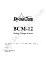
1
om
m
.c
ar
ea
m
al
BCM-12
ww
w.
B
Battery Charge Monitor
Installation and User Manual for the BCM – 12 Battery Charge
Monitor.
Full Version
File: BCMrev3.0man.doc
March 3, 2005
2
Thank You For Purchasing This DynaGen Product
m
.c
om
Please Read Manual Before Installing Unit
Receipt of Shipment and Warranty Return Information
ar
Upon receipt of shipment, carefully remove the unit from the shipping container and thoroughly
examine the unit for shipping damage. In case of damage, immediately contact the carrier and
request that an inspection report be filed prior to contacting DynaGen.
ea
m
Limited Warranty
al
All returned items are to be shipped prepaid and include a Return Material Authorization (RMA)
number issued by DynaGen. RMA forms are available by contacting DynaGen Technical
Support through the contact methods listed below.
ww
w.
B
DynaGen will repair or replace any BCM, which proves to be defective under normal and proper
use within Two Years from the date of shipment. This constitutes the only warranty and no other
warranty shall be implied.
We welcome your comments and suggestions. Please contact us at:
DynaGen Technologies Inc.
Phone: 1-888-396-2436
(902) 562 0133
Fax: (902) 567 0633
Email: [email protected]
WEB SITE: www.dynagen.ca
Operating & Installation Manual for Battery Charge Monitor (BCM)
3
Table of Contents
1
om
SPECIFICATIONS
WIRING DIAGRAMS
BCM general wiring
BCM wiring with ES5x engine controller
BCM wiring with GSC300 engine controller
ww
w.
B
ea
m
SYSTEM OPERATING STATES
IDLE State
Delay on State
Charging State
al
ar
ADJUSTMENTS AND SETUP PROCEDURES
LOW trip setting
HIGH trip set point
Maximum run time calibration
Delay on calibration
5
5
6
7
m
.c
WIRING INSTALLATION GUIDELINES
Wiring instructions, types and sizes
Wiring guidelines
Terminal description
Operating & Installation Manual for Battery Charge Monitor (BCM)
8
8
9
10
11
11
12
12
13
14
14
14
14
4
(4.75 VDC min.- 18VDC max.)
Standby current draw:
12 mA
Operating current draw:
160 mA
Operating temperature range:
-20 O C ⇒ +85 O C
Operating humidity range:
0 ⇒ 95% non-condensing
Run output:
5 Amps max. continuous
sourcing(+bat) output
High/Low pot adjustment
Range
10 – 15 VDC
Actual unit weight:
0.45 lb.
ar
1 lb. (0.45kg)
3.25” x 3.25” x 0.5”
ea
m
Unit dimensions:
al
Shipping weight:
m
.c
Operating VDC limits:
4” (10.16cm) x 4” (10.16cm) x 3” (7.62cm)
ww
w.
B
Shipping dimensions:
om
SPECIFICATIONS
Operating & Installation Manual for Battery Charge Monitor (BCM)
5
om
WIRING INSTALLATION GUIDELEINES
m
.c
Danger: Never work on the engine while its power is on. This
Battery Charge Monitor does not generate a warning signal prior to
automatic engine start. Warning signs should be placed on engine
equipment indicating this important safety measure.
Following these instructions will help avoid common installation problems during wiring and
setup.
al
ar
• Battery (Terminal 1 & 2) must be disconnected before any wiring connections are made.
Battery disconnection can easily be accomplished by removing terminal block from BCM
unit.
• Wire length from the BCM unit to operating equipment, should not exceed 30 feet. Longer
runs may require the use of heavier gauge wiring.
• Do not connect high voltage AC circuits to the BCM unit.
ea
m
Wiring size should be minimum 18AWG. Use stranded wire, since solid wire has a tendency to
crack, break and loosen over time.
ww
w.
B
NOTE:
• When making connections to BCM’s removable terminal block, ensure that there are no wire
strands that are exposed. Exposed strands may cause shorting to adjacent wiring terminals.
• Ensure that wire connections to removable terminal block are securely fastened, since
vibrations have a tendency to loosen wiring connections over time.
Terminal
1
2
3
4
5
6
7
8
Wire Size
14 – 18
14 – 18
14 – 18
14 – 18
14 – 18
18
N/C
N/C
Current Max.
10A
10A
10A
10A
10A
0.1A
N/C
N/C
Function
Battery positive (+)
Battery positive (+)
Battery negative (-)
Battery negative (-)
Start/Run Relay output
Sensing Input
N/C
N/C
Operating & Installation Manual for Battery Charge Monitor (BCM)
6
WIRING GUIDELINES
om
1. DO NOT use wire smaller than 18 AWG.
2. DO NOT short Run output to ground, as this will cause 20A fuse to blow, and may cause
damage to on board relay contacts.
m
.c
3. Replace on board 20A fuse with similar type and rating (Replacement fuse to be Blade type
MINI FUSE rated 20 Amps maximum). Never bypass fuse with jumper, as this will not
protect unit in the event of a short circuit or overload condition.
4. DO NOT exceed the maximum rated current and voltage on the BCM output. Do not exceed
10 amps for Run output.
Installation of a diode is not required across Run output. An internal fast switching diode is
provided to protect the BCM output from inductive kick-back. However, diodes should be
placed across external slave relay contacts when used to actuate any inductive loads, such as
solenoids, to protect the contacts from damage caused by arcing. In addition to prolonging
the useful life of the relays, placing such diodes will enormously reduce generated electrical
noise.
ea
m
al
6.
ar
5. Do not reverse power supply connections to the BCM unit as this will result in permanent
damage to unit.
7. DO NOT short potentiometer jumpers to ground, as this may result in damage to BCM unit.
These jumpers are located adjacent to the potentiometers on rear of unit, they provide a
method for simple and easy calibration of LOW, HIGH and RUN TIME set points.
8. There is a potentiometer, which is just below the potting, adjacent to the Run relay. DO NOT
ww
w.
B
attempt to adjust this pot. This pot has been calibrated at the factory and does not require
field adjustment. Adjusting this pot will greatly affect the sensing accuracy of the BCM unit.
9. Replace On board relay with similar type and rating. Some replacement types are as follows:
•
•
•
Bosch
American Zettler
Aromat
Part # 0 332 207 307
Part # AZ977-1A-12D
Part # CM1–R –12V
Operating & Installation Manual for Battery Charge Monitor (BCM)
7
TERMINAL DESCRIPTION
Description
1&2
+ Battery connection to BCM unit. This connection is fused through the on board
20 Amp replaceable fuse. This provides main power to operate BCM unit.
Battery ground connection for the controller module. A good ground connection,
directly from the battery, is required for proper operation.
Run Output. This output closes to + Battery when actuated. This output energizes
only after a delay on period, when a low battery condition is present.
Sense input. This input is used to monitor battery status. If the same battery that
powers up the unit is the battery that is required to be monitored, simply connect
the sense input (T#6) to one of the battery terminals (T#1 or T#2).
Not Used
Not Used
5
6
ww
w.
B
ea
m
al
ar
7
8
m
.c
3&4
om
Term #
Operating & Installation Manual for Battery Charge Monitor (BCM)
8
ww
w.
B
ea
m
al
ar
m
.c
om
WIRING DIAGRAMS
Operating & Installation Manual for Battery Charge Monitor (BCM)
ww
w.
B
ea
m
al
ar
m
.c
om
9
Operating & Installation Manual for Battery Charge Monitor (BCM)
ww
w.
B
ea
m
al
ar
m
.c
om
10
Operating & Installation Manual for Battery Charge Monitor (BCM)
11
ADJUSTMENTS AND SETUP PROCEDURES
follow all safety guidelines and wiring procedures.
om
Warning: The following procedures will require BCM operation. Be sure to
ar
m
.c
NOTE:
“Potentiometer” is abbreviated as “pot” throughout. To increase a pot’s setting, turn it
clockwise; to decrease it, counter-clockwise. These Pots are 25 turns nominal, therefore turn
pots fully 25 turns to ensure that you are at either the minimum or maximum setting. The rear of
the BCM unit contains three adjustable pots, and an eight position DIP switch, only 3 switches
are implemented on this unit.
The steps for calibration of the BCM unit to a specific system is as follows:
al
Calibration of LOW trip set point.
Calibration of HIGH trip set point.
Adjustment of Maximum run time setting.
Adjustment of Delay On timer setting.
ea
m
1.
2.
3.
4.
1. LOW SET POINT CALIBRATION:
ww
w.
B
The low set point range spans from 10 – 15VDC. This set point is adjustable via an on board
Pot. There is a green LED adjacent to the Pot (LOW), which illuminates when the sense input
voltage has gone below the low set point. There is also a jumper adjacent to the LOW pot,
which allows for pot calibration.
The simplest and most precise method for calibration is as follows.
1. Connect battery positive (10 – 15 VDC) to BCM terminal #1 or #2, and connect battery
negative to BCM terminal #3 or #4.
2. Measure the voltage on the jumper adjacent to the LOW Potentiometer. The Low set point
will be the voltage measured at the jumper pin +10. [LOW SETPOINT= V measured +10
VDC]
i.e. If a LOW set point of 12.1VDC is required, you must adjust the low potentiometer until
the voltage at the LOW POT reads 2.1VDC.
Operating & Installation Manual for Battery Charge Monitor (BCM)
12
2. HIGH SETPOINT CALIBRATION:
The simplest and most precise method for calibration is as follows.
om
The HIGH set point range spans from 10 – 15VDC. This set point is adjustable via an on board
Pot. There is a red LED adjacent to the Pot (HIGH), which illuminates when the sense input
voltage has gone above the HIGH set point. There is also a jumper adjacent to the HIGH pot,
which allows for pot calibration.
m
.c
1. Connect battery positive (10 - 15 VDC) to BCM terminal #1 or #2, and connect battery
negative to BCM terminal #3 or #4.
2. Measure the voltage on the jumper adjacent to the HIGH Potentiometer. The HIGH set point
will be the voltage measured at the jumper pin +10.
[HIGH SETPOINT= V measured +10 VDC]
ar
i.e. If a HIGH set point of 14.2VDC is required, you must adjust the HIGH potentiometer
until the voltage at the HIGH POT reads 4.2VDC.
al
3. MAXIMUM RUN TIME CALABRATION:
ea
m
The Maximum Run time setting is adjustable from 0 – 512 minutes (0 – 8.5 hrs). This setting
adjusts the maximum ON time for the Run output. i.e. if the HIGH set point has not been
reached prior to the maximum run time, the Run output turns OFF, and the BCM waits for yet
another LOW voltage condition.
Calibration of maximum run time is as follows:
ww
w.
B
1. Connect battery positive (10 - 15 VDC) to BCM terminal #1 or #2, and connect battery
negative to BCM terminal #3 or #4.
2. Measure the voltage on the jumper adjacent to the MAX. RUN TIME Potentiometer. The
MAX RUN TIME set point will be as follows:
[MAX RUN TIME = (V measured * 512)/5)]
i.e. If a MAX RUN TIME of 5 minutes is required then you must adjust the MAX RUN
TIME potentiometer until the voltage at the MAX RUN TIME POT reads 0.0488 VDC.
V meas. = (MAX RUN TIME * 5)/512 = (5*5)/512
Operating & Installation Manual for Battery Charge Monitor (BCM)
13
4. DELAY ON TIME CALIBRATION:
om
The Delay ON timer provides an adjustable delay for activation of the Run output. i.e. if the
sense input voltage drops below the LOW set point, the BCM delays the activation of the Run
relay for the delay ON period.
The Delay ON timer function is configurable from DIP switches 1, 2 & 3. The Delay ON timer
has eight possible settings as follows:
SW 3
ON
OFF
ON
OFF
ON
OFF
ON
OFF
m
.c
SW 2
ON
ON
OFF
OFF
ON
ON
OFF
OFF
ar
SW1
ON
ON
ON
ON
OFF
OFF
OFF
OFF
al
Delay ON time (minutes)
0
1
2
3
4
5
6
7
ea
m
You may want to record your settings below for future reference
USER SETTINGS:
ww
w.
B
LOW SETPOINT
HIGH SETPOINT
MAX. RUN TIME
DELAY ON TIME
Operating & Installation Manual for Battery Charge Monitor (BCM)
14
SYSTEM OPERATING STATES
om
There are 3 main operating states for the Battery Charge Monitor, they are as follows:
m
.c
A. IDLE
B. DELAY ON
C. CHARGING
IDLE:
al
DELAY ON TIMING:
ar
Idle state is assumed when the unit is powered-up (power applied to +Battery terminal),
but not told to run (sense input has not gone below low voltage set point).
In Idle state, when sense input voltage drops below the LOW voltage set point, we
proceed to the Delay ON timing state.
ea
m
The Delay ON timing state ensures that the Sensing input voltage is below the low set
point for a period of time. This delay prevents unnecessary starts of operating equipment.
The Delay on time is adjustable via an onboard DIP SWITCH. When the delay ON time
has elapsed, the BCM unit proceeds to Charging.
CHARGING:
ww
w.
B
In the charging state the BCM unit continually monitors for a high battery condition.
When the sensing input voltage goes above the HIGH voltage set point, the BCM unit deenergizes the RUN relay and proceeds to the IDLE state of operation.
Operating & Installation Manual for Battery Charge Monitor (BCM)