1
3OXPELQJ'LDJUDPV
We have given some example plumbing layouts of how the appliance can be installed in
typical situations; these diagrams should be taken as a guide only and not as a definitive
instruction. It is the sole responsibility of the plumbing and heating engineer carrying out
the installation to design the system to suit the property and the clients needs.
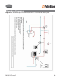
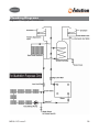
The following diagrams are offered as a guide to assist in system design:
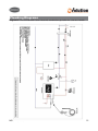
Diagram A
Pressurised boiler stove linked with combination gas boiler via a low loss header
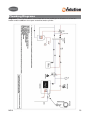
Diagram B
Pressurised boiler stove linked with a non combi gas or oil boiler via a low loss header and
the addition of an open vented hot water cylinder.
Diagram C
Pressurised boiler stove linked with a non combi gas or oil boiler via a low loss header and
the addition of a pressurised hot water cylinder.
Diagram D
Pressurised stove linked with a non combi gas or oil boiler via a thermal store with solar for
summer time domestic hot water
Diagram E
Pressurised boiler stove linked with a non combi gas or oil boiler via a thermal store with
solar for domestic hot water and solar support for central heating system.
Diagram F
Stand alone pressurised boiler stove with an open vented hot water cylinder
Diagram G
Stand alone pressurised boiler stove with a pressurised hot water cylinder.
Diagram H
2 pipe open vented system
MS10-11C Issue 2
21