1
AA G610.book Page i Monday, October 22, 2001 9:46 AM
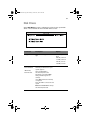
Acer Altos G610
User’s guide
AA G610.book Page ii Monday, October 22, 2001 9:46 AM
Copyright © 2001 Acer Incorporated
All Rights Reserved.
Acer Altos G610
User’s guide
Changes may be made periodically to the information in this publication without obligation
to notify any person of such revision or changes. Such changes will be incorporated in new
editions of this manual or supplementary documents and publications. This company makes
no representations or warranties, either expressed or implied, with respect to the contents
hereof and specifically disclaims the implied warranties of merchantability or fitness for a
particular purpose.
Record the model number, serial number, purchase date, and place of purchase information in
the space provided below. The serial number and model number are recorded on the label
affixed to your computer. All correspondense concerning your unit should include the serial
number, model number, and purchase information.
No part of this publication may be reproduced, stored in a retrieval system, or transmitted, in
any form or by any means, electronic, mechanical, photocopy, recording, or otherwise,
without the prior written permission of Acer Incorporated.
Model Number : _________________________________
Serial Number: ___________________________________
Purchase Date: ___________________________________
Place of Purchase: ________________________________
Acer and the Acer Logo are registered trademarks of Acer Inc. Other company’s product
names or trademarks are used herein for identification purposes only and belong to their
respective companies.
AA G610.book Page iii Monday, October 22, 2001 9:46 AM
iii
Notices
FCC notice
This device has been tested and found to comply with the limits for a Class B
digital device pursuant to Part 15 of the FCC Rules. These limits are designed to
provide reasonable protection against harmful interference in a residential
installation. This device generates, uses, and can radiate radio frequency
energy, and if not installed and used in accordance with the instructions, may
cause harmful interference to radio communications.
However, there is no guarantee that interference will not occur in a particular
installation. If this device does cause harmful interference to radio or television
reception, which can be determined by turning the device off and on, the user
is encouraged to try to correct the interference by one or more of the following
measures:
•
Reorient or relocate the receiving antenna
•
Increase the separation between the device and receiver
•
Connect the device into an outlet on a circuit different from that to which
the receiver is connected
•
Consult the dealer or an experienced radio/television technician for help
Notice: Shield cables
All connections to other computing devices must be made using shielded cables
to maintain compliance with FCC regulations.
Notice: Peripheral devices
Only peripherals (input/output devices, terminals, printers, etc.) certified to
comply with the Class B limits may be attached to this equipment. Operation
with noncertified peripherals is likely to result in interference to radio and TV
reception.
Caution! Changes or modifications not expressly approved by the
manufacturer could void the user’s authority, which is granted by
the Federal Communications Commission, to operate this
computer.
AA G610.book Page iv Monday, October 22, 2001 9:46 AM
iv
Use conditions
This part complies with Part 15 of the FCC Rules. Operation is subject to the
following two conditions: (1) this device may not cause harmful interference,
and (2) this device must accept any interference received, including interference
that may cause undesired operation.
Notice: Canadian users
This Class B digital apparatus meets all requirements of the Canadian
Interference-Causing Equipment Regulations.
Remarque à l’intention des utilisateurs canadiens
Cet appareil numérique de la classe B respected toutes les exigences du
Règlement sur le matériel brouilleur du Canada.
Important safety instructions
Read these instructions carefully. Save these instructions for future
reference.
1
Follow all warnings and instructions marked on the product.
2
Unplug this product from the wall outlet before cleaning. Do not
use liquid cleaners or aerosol cleaners. Use a damp cloth for
cleaning.
3
Do not use this product near water.
4
Do not place this product on an unstable cart, stand, or table. The
product may fall, causing serious damage to the product.
5
Slots and openings in the cabinet and the back or bottom are
provided for ventilation; to ensure reliable operation of the
product and to protect it from overheating, these openings must
not be blocked or covered. The openings should never be blocked
by placing the product on a bed, sofa, rug, or other similar surface.
This product should never be placed near or over a radiator or
heat register, or in a built-in installation unless proper ventilation
is provided.
6
This product should be operated from the type of power indicated
on the marking label. If you are not sure of the type of power
available, consult your dealer or local power company.
AA G610.book Page v Monday, October 22, 2001 9:46 AM
v
7
Do not allow anything to rest on the power cord. Do not locate
this product where persons will walk on the cord.
8
If an extension cord is used with this product, make sure that the
total ampere rating of the equipment plugged into the extension
cord does not exceed the extension cord ampere rating. Also,
make sure that the total rating of all products plugged into the
wall outlet does not exceed the fuse rating.
9
Never push objects of any kind into this product through cabinet
slots as they may touch dangerous voltage points or short out
parts that could result in a fire or electric shock. Never spill liquid
of any kind on the product.
10 Do not attempt to service this product yourself, as opening or
removing covers may expose you to dangerous voltage points or
other risks. Refer all servicing to qualified service personnel.
11 Unplug this product from the wall outlet and refer servicing to
qualified service personnel under the following conditions:
a
When the power cord or plug is damaged or frayed
b
If liquid has been spilled into the product
c
If the product has been exposed to rain or water
d
If the product does not operate normally when the operating
instructions are followed. Adjust only those controls that are
covered by the operating instructions since improper
adjustment of other controls may result in damage and will
often require extensive work by a qualified technician to
restore the product to normal condition.
e
If the product has been dropped or the cabinet has been
damaged
f
If the product exhibits a distinct change in performance,
indicating a need for service.
12 Replace the battery with the same type as the product's battery we
recommend. Use of another battery may present a risk of fire or
explosion. Refer battery replacement to a qualified serviceman.
13 Warning! Batteries may explode if not handled properly. Do not
disassemble or dispose of them in fire. Keep them away from
children and dispose of used batteries promptly.
AA G610.book Page vi Monday, October 22, 2001 9:46 AM
vi
14 Use only the proper type of power supply cord set (provided in
your accessories box) for this unit. It should be a detachable type:
UL listed/CSA certified, type SPT-2, rated 7A 125V minimum, VDE
approved or its equivalent. Maximum length is 15 feet (4.6
meters).
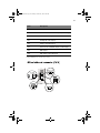
Laser compliance statement
The CD-ROM drive in this computer is a laser product. The CD-ROM drive’s
classification label (shown below) is located on the drive.
CLASS 1 LASER PRODUCT
CAUTION: INVISIBLE LASER RADIATION WHEN OPEN. AVOID EXPOSURE TO
BEAM.
Notices
FCC notice
Important safety instructions
Laser compliance statement
iii
iii
iv
vi
1 System overview
1
Overview
Processors
Memory
System chipsets
Expansion slots
Hardware management support
Features summary
3
3
4
4
6
6
7
2 System tour
External and internal structure
Front panel
Rear panel
Internal components
Keyboard
Mouse
Disk drives
3.5-inch floppy drive
CD-ROM drive
Setting up your system
Preinstallation requirements
Basic connections
Connecting the PS/2 keyboard
Connecting the PS/2 mouse
Connecting the VGA monitor
Connecting to the network
Connecting the power cable
Turning on your system
Power-on problems
Turning off your system
Connecting options
Printer
USB devices
System rack installation
Vertical mounting hole pattern
Screw types used
Installing cage nuts
9
11
11
12
13
15
17
18
18
19
20
20
21
21
22
23
24
25
26
27
28
29
29
30
31
31
32
33
Contents
AA G610.book Page vii Monday, October 22, 2001 9:46 AM
AA G610.book Page viii Monday, October 22, 2001 9:46 AM
Installing the system into the rack
3 Upgrading your system
Installation precautions
ESD precautions
Preinstallation instructions
Post-installation instructions
Opening your system
Opening the front panel door
Removing the front panel door
Removing the side panel
System boards
Mainboard layout
BPL5M jumpers and connectors
SAF-TE card layout
BPL5M hot-swap cage components
Installing the BPL5M hot-swap cage
Removing the BPL5M hot-swap cage
Installing a hard disk into the BPL5M tray
Installing and removing storage devices
Replacing the 3.5-inch floppy drive
Replacing a 5.25-inch storage device (optional)
Removing and installing the CPU
Removing a CPU
Installing a CPU
Removing and installing memory modules
Removing a DIMM
Installing a DIMM
Installing expansion cards
Hot-swappable redundant power supply module
Removing a 337-watt hot-swappable
redundant power supply module
Installing a 337-watts hot-swappable
redundant power supply module
Installing an internal system fan
34
47
49
49
49
50
51
51
51
52
54
54
58
60
61
61
62
63
65
65
66
69
69
71
73
73
74
75
77
77
78
79
4 BIOS Setup utility
81
BIOS Setup utility
Entering Setup
System Information
Product Information
Disk Drives
IDE Channel Type
83
84
86
88
89
90
AA G610.book Page ix Monday, October 22, 2001 9:46 AM
Onboard Peripherals
Power Management
Boot Options
Date and Time
System Security
Setting and changing the password
Removing a password
IPMI Configuration
RDM Configuration
Advanced Options
Memory/Cache Options
PnP/PCI Options
CPU Frequency
Chipset Settings
Load Default Settings
Abort Settings Change
Exit Setup
93
96
99
102
103
105
106
107
109
113
114
115
118
119
121
122
123
Appendix A: ASM Pro quick installation guide 125
Installing ASM Pro
System requirements
System setup
Installing ASM Pro Console
Installing ASM Pro Server Agent
Installing RDM
System requirements
Connecting communication peripherals
RDM Console setup
Installing AWM and Microsoft Internet
Information Service (IIS)
System requirements
Installing AWM
Setting up Microsoft IIS
Running AWM
127
127
127
128
128
135
135
136
139
141
141
141
142
143
Index
145
AA G610.book Page x Monday, October 22, 2001 9:46 AM
AA G610.book Page 1 Monday, October 22, 2001 9:46 AM
1 System overview
AA G610.book Page 2 Monday, October 22, 2001 9:46 AM
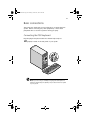
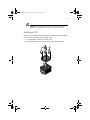
The Acer Altos G610 server model is a
powerful dual-processor system loaded with
a host of new and innovative features. The
system offers a new standard for flexible
productivity ideal for local or wide area
networks and multiuser server environments.
AA G610.book Page 3 Monday, October 22, 2001 9:46 AM
3
Overview
The Acer Altos G610 server model utilizes a PCI bus based dualprocessor mainboard built on an ATX baseboard. It comes with two
FC-PGA (Flip-Chip Pin-Grip Array) processor sockets that support an
Intel® Pentium® III processor running at 933 MHz and 1 GHz or an Intel
Pentium III processor running at 512K 1.13 and 1.26 GHz. The processor
is integrated with the Server Works LE III north and south bridge
chipsets. The mainboard also supports the Intel 82559 10/100 Mbps PCI
Ethernet chipset with WOL (Wake on LAN) function for better remote
site management.
For expandability, the mainboard includes four 64 bit/33 MHz PCI bus
slots and two 32 bit/33 MHz PCI bus slots. In addition, the mainboard
supports four DIMM sockets that allow memory installation up to a
maximum of 4 GB using four 1024-MB SDRAM (Synchronous DRAM)
modules.
For connectivity, the mainboard provides two USB (Universal Serial Bus)
connectors, PS/2 interface for both mouse and keyboard and other
standard features such as two UART NS 16C550 serial ports, enhanced
parallel port with Enhanced Parallel Port (EPP)/Extended Capabilities
Port (ECP) support, one RJ-45 network port and one VGA/monitor port.
The system is fully compatible with Windows 2000 Server, Novell
Netware, Red Hat Linux, Windows NT 4.0, and SCO Unixware.
Processors
The Pentium III processor delivers higher performance than previous
Pentium processors while maintaining binary compatibility with all
previous Intel Architecture processors.
The mainboard supports 100 or 133 MHz GTL+ host bus frequencies for
two Pentium III processors running at 933 Mhz and 1 GHz or two Intel
Pentium III processors running at 512K 1.13 and 1.26 GHz and future
generation of Pentium III processors.
AA G610.book Page 4 Monday, October 22, 2001 9:46 AM
4
1 System overview
Memory
The four DIMM sockets on board accept four 1024-MB registered
SDRAM DIMMs for a maximum memory capacity of 4 GB.
For data integrity, the default setting of the ECC (error correcting code)
function of the memory system in BIOS is enabled. Refer to “IPMI
Configuration” on page 107 for more information on this BIOS
parameter.
Note: The SDRAM module should work under 3.3 volts only;
5-volt memory devices are not supported.
The system board supports both 100 and 133 MHz registered SDRAMs;
66 MHz SDRAMs are not supported.
System chipsets
Server Works LE III north and south bridge
The Server Works LE III north and south bridge chipsets are specifically
designed to meet the needs of high performance systems.
•
CNB30LE (champ north bridge) is in charge of the host bus
interfacing and memory bus control. The north bridge provides
one 32-bit PCI bus running at 33 MHz and one 64-bit secondary PCI
bus running at 33/66 MHz.
•
OSB4 (open south bridge) subset provides the legacy ISA interface,
USB port, ATA33, and System Management (SM) bus. The BMC
(Baseboard Management Control) board is attached to the
mainboard and connected to the south bridge that supports the
ASM and RDM functions and the industry standard IPMI protocol
as well.
AA G610.book Page 5 Monday, October 22, 2001 9:46 AM
5
SCSI subsystem
The dual-channel AIC-7899 single-chip host adapter delivers Ultra
160/m SCSI data transfer rates which double the Ultra-2 SCSI data
transfer rate up to 160 MByte/s. With two channels, it delivers a total
of 320 MByte/s bandwidth. In addition, the AIC-7899 features a 66
MHz, 64-bit PCI interface that supports zero wait-state memory which
also operates on 33 MHz, 32-bit PCI buses. It supports up to 15 devices
on a 12-meter cable (or 25 meters in a point-to-point configuration),
making it ideal for both clustering and RAID configurations.
LAN subsystem
Another cost-effective feature for network solutions is the integration
of Intel’s 82559 10/100 Mbps Fast Ethernet controller which supports:
•
Advanced Configuration and Power Interface (ACPI) 1.20A-based
power management
•
wake on Magic Packet
•
wake on Interesting Packet
•
advanced System Management Bus (SMB) based manageability
•
Wired for Management (WfM) 2.0 compliance
•
IP checksum assist
•
PCI 2.2 compliance
•
SDG 2.0 compliance
Video subsystem
The ATI Rage XL harbors 2D and 3D display capabilities that bring life
to any multimedia and work applications. With remarkable color depth
and high resolutions of up to 1280 x 1024, it provides an enhanced
visual experience on your system.
The onboard ATI Rage XL chipset comes with 4 MB VRAM (video RAM)
and supports up to 1024 x 768 display mode at high colors.
AA G610.book Page 6 Monday, October 22, 2001 9:46 AM
6
1 System overview
Expansion slots
PCI bus
The system board has six PCI bus slots contained in two PCI segments:
•
Four 64-bit/33 MHz PCI bus slots (PCI slots 1 to 4)
•
Two 32-bit/33 MHz PCI bus slots (PCI slots 5 to 6)
The PCI bus is the key interface that communicates between the north
and the south bridge.
Hardware management support
The mainboard supports a power management function that conforms
to the power saving standards of the U.S. Environmental Protection
Agency (EPA) Energy Star program. It also offers Plug-and-Play feature
which helps save users from configuration problems, thus making the
system more user-friendly.
Additional features include hardware support for ASM Pro (Advanced
System Manager Pro) and RDM (Remote Diagnostic Management).
ASM detects problems in the CPU thermal condition, CPU working
voltage detection (±12V/±5V/3.3V/1.5V), and PCI bus utilization
calculation. It also detects if the CPU fan or the chassis fan
malfunctions. Meanwhile, RDM allows execution of the RDM
diagnostic program from a remote RDM station to fix detected
problems or to reboot the system.
AA G610.book Page 7 Monday, October 22, 2001 9:46 AM
7
Features summary
The mainboard has the following major components:
•
Two FC-PGA processor sockets that support an Intel Pentium III
processor running at 933 Mhz and 1 GHz or an Intel Pentium III
processor running at 512K 1.13 and 1.26 GHz as well as future
generations of Pentium III CPUs
•
Server Works LE III north and south bridge
•
Onboard Intel 82559 10/100 Mbps LAN chip with WOL support
•
•
•
•
Adaptec® AIC-7899 Dual Channel SCSI controller chipset supports:
Channel A - one 68-pin Ultra160/m SCSI connector
Channel B - one 68-pin Ultra 160/m SCSI connector
Four DIMM sockets that accept four 1024-MB registered SDRAM
DIMMs for a maximum memory capacity of 4 GB
•
•
•
Six PCI bus slots
Four 64-bit/33 MHz PCI bus slots (PCI slots 1 to 4)
Two 32-bit/33 MHz PCI bus slots (PCI slots 5 to 6)
•
System clock/calendar with battery backup
•
IDE disk drive interface
•
Super I/O chipset
•
Hardware support for ASM Pro (Advanced System Manager Pro)
and RDM (Remote Diagnostic Management)
•
External ports:
Two USB connectors
PS/2-compatible mouse and
keyboard ports
• Parallel port
•
•
•
•
Monitor/VGA port
RJ-45 network port
•
Two serial ports
AA G610.book Page 8 Monday, October 22, 2001 9:46 AM
8
1 System overview
AA G610.book Page 9 Monday, October 22, 2001 9:46 AM
2 System tour
AA G610.book Page 10 Monday, October 22, 2001 9:46 AM
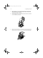
This chapter discusses the features and components
of your system. Instructions on how to set up your
system and connect basic and optional peripherals
are also explained.
AA G610.book Page 11 Monday, October 22, 2001 9:46 AM
11
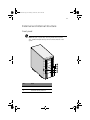
External and internal structure
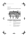
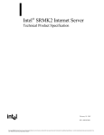
Front panel
Note: One pair of system keys are hung inside the front panel
door. Additional duplicate keys can be found at the back of the
system.
No.
Item
1
Power indicator
2
Hard disk activity indicator
AA G610.book Page 12 Monday, October 22, 2001 9:46 AM
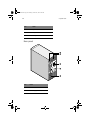
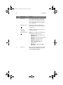
12
2 System tour
No.
Item
3
System status indicator
4
Keylock
5
Front panel door
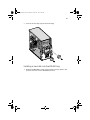
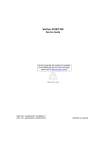
Rear panel
No.
Item
1
Power cable socket
2
Power supply modules
AA G610.book Page 13 Monday, October 22, 2001 9:46 AM
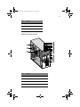
13
No.
Item
3
Housing fan
4
I/O connectors (color-coded)
5
Expansion slots
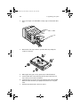
Internal components
No.
Item
1
CD-ROM Headphone/Earphone port
2
Volume Decrease/Increase button
3
CD-ROM activity indicator
4
CD-ROM tray
AA G610.book Page 14 Monday, October 22, 2001 9:46 AM
14
2 System tour
No.
Item
5
CD-ROM Play/Forward button
6
CD-ROM Stop/Eject button
7
Floppy drive eject button
8
Floppy drive tray
9
Floppy drive activity indicator
10
Power button
11
Power indicator
12
Hard disk activity indicator
13
System status indicator
14
Removable hard drive trays
15
Expansion slots
16
Housing fan
17
Power supply modules
AA G610.book Page 15 Monday, October 22, 2001 9:46 AM
15
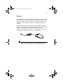
Keyboard
Your system comes with a PS/2 keyboard. The keyboard has full-sized
keys that include separate cursor keys, two Windows keys, and twelve
function keys.
No.
Component
Function
1
Function keys
(F1 - F12)
Access most of the computer’s controls like
screen brightness, volume output and the
BIOS Setup utility.
2
Scroll Lock
When activated, the screen moves one line
up or down when you press the up arrow
or down arrow respectively. Take note
that Scroll Lock may not work with some
applications.
3
Num Lock
When activated, the keypad is set to
numeric mode, i.e., the keys function as a
calculator (complete with arithmetic
operators such as +, -, x, and /).
AA G610.book Page 16 Monday, October 22, 2001 9:46 AM
16
2 System tour
No.
Component
Function
4
Cursor keys
Also called the arrow keys. These keys let
you move the cursor around the screen.
They serve the same function as the arrow
keys on the numeric pad when the Num
Lock is toggled off.
5
Application key
Opens the applications context menu
(same function as clicking the right button
of the mouse).
6
Palm rest
Provides a comfortable place to rest your
hands while typing.
(detachable)
7
8
Windows logo key
Caps Lock
Start button. Combinations with this key
perform special functions, such as:
•
Windows + Tab: Activate the next
Taskbar button
•
Windows + E: Explore My Computer
•
Windows + F: Find Document
•
Windows + M: Minimize All
•
Shift + Windows + M: Undo
Minimize All
•
Windows + R: Displays the Run
dialog box
When activated, all alphabetic characters
typed appear in uppercase (same function
as pressing Shift + <letter>).
AA G610.book Page 17 Monday, October 22, 2001 9:46 AM
17
Mouse
Your PS/2 mouse has one ratchet wheel and two buttons: a left button
and a right button. Quickly pressing and releasing the buttons is called
clicking. Sometimes, you will need to do a double-click (clicking the
same button twice quickly) or a right-click (clicking the right button
quickly).
The ratchet wheel in between the two buttons is added to provide
easier scrolling capability. By simply moving the wheel with your index
finger, you can quickly move through multiple pages, lines, or
windows. The wheel may also function as a third button allowing you
to quickly click or double-click an icon or a selected item.
Note: If you are left-handed, refer to your Windows manual for
instructions on how to set up your mouse for left-handed use.
AA G610.book Page 18 Monday, October 22, 2001 9:46 AM
18
2 System tour
Disk drives
Your system comes with the following disk drives:
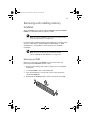
3.5-inch floppy drive
Your system’s 3.5-inch floppy drive can handle 720-KB, 1.2, 1.44 and
2.88-MB capacity diskettes.
Floppy diskettes are compact, lightweight, and easy to carry around.
Here are some tips on how to take care of your diskettes:
•
Always make backup copies of the diskettes that contain
important data or program files.
•
Keep diskettes away from magnetic fields and sources of heat.
•
Avoid removing a diskette from the floppy drive when the drive
activity indicator is on.
•
Write-protect your diskettes to prevent accidental erasure. To do
this, slide the write-protect tab to the write-protect position (1).
Sliding the write-protect tab to the not-write-protect position (2)
will allow you to store and modify data in your diskettes.
•
When you put a label on a 3.5-inch diskette, make sure that the
label is properly attached (flat on the surface) and within the
labeling area (area with a slight surface depression) on the
diskette. An improperly attached label may cause a diskette to get
stuck in the floppy drive when you are inserting or removing it.
AA G610.book Page 19 Monday, October 22, 2001 9:46 AM
19
CD-ROM drive
Your system comes with a CD-ROM drive. This drive is located on the
front panel of your system. The CD-ROM drive allows you to play
different types of compact discs (CDs) and video CDs.
CDs, like diskettes, are also compact, lightweight, and easy to carry
around. However, they are more delicate than diskettes and must be
handled with extra care.
To insert a CD into your system’s CD-ROM drive:
1
Gently push the Stop/Eject button located on the front panel.
2
When the disc tray slides open, insert the CD. Make sure that the
label or title side of the disc is facing upward.
Caution! Hold the disc by the edges to avoid leaving smudges or
fingerprints.
3
Push the Stop/Eject button again to close the tray.
To take care of your CDs:
•
Keep your discs in a disk case when not in use to avoid scratches or
other damage. Any kind of dirt or damage can affect the data on
the disc, impair the disc lens reader on the CD-ROM drive, or stop
the system from successfully reading the disc.
•
When handling discs, always hold them by the edges to avoid
smudges or fingerprints.
•
When cleaning discs, use a clean, dust-free cloth and wipe in a
straight line from the center to the edge. Do not wipe in a circular
motion.
•
Clean your CD-ROM drive periodically. You may refer to a cleaning
kit for instructions. Cleaning kits can be purchased in any system
or electronics shop.
AA G610.book Page 20 Monday, October 22, 2001 9:46 AM
20
2 System tour
Setting up your system
Preinstallation requirements
Selecting a site
Before unpacking and installing the system, select a suitable site for
the system for maximum efficiency. Consider the following factors
when choosing a site for the system:
•
Near a grounded power outlet
•
Clean and dust-free
•
Sturdy surface free from vibration
•
Well-ventilated and away from sources of heat
•
Secluded from electromagnetic fields produced by electrical
devices such as air conditioners, radio and TV transmitters, etc.
Checking the package contents
Check the following items from the package:
•
Acer Altos G610 ystem
•
Acer Altos G610 User’s guide (with system binder)
•
CD-ROM driver kit
•
System keys (hung inside the front panel door)
If any of the above items are damaged or missing, contact your dealer
immediately.
Save the boxes and packing materials for future use.
AA G610.book Page 21 Monday, October 22, 2001 9:46 AM
21
Basic connections
The system unit, keyboard, mouse, and monitor constitute the basic
system. Before connecting any other peripherals, connect these
peripherals first to test if the system is running properly.
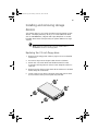
Connecting the PS/2 keyboard
Plug the plug the keyboard cable into the PS/2 keyboard port
(purple) located on the rear panel of your system.
Note: If you are using a USB keyboard, plug the USB keyboard
cable into either USB ports (black ports) located on the rear panel
of your system.
AA G610.book Page 22 Monday, October 22, 2001 9:46 AM
22
2 System tour
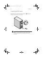
Connecting the PS/2 mouse
Plug the PS/2 mouse cable into the PS/2 mouse port
located on the rear panel of your system.
(green port)
Note: If you are using a USB mouse, plug the USB mouse cable
into either USB ports (black ports) located on the rear panel of
your system.
AA G610.book Page 23 Monday, October 22, 2001 9:46 AM
23
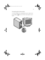
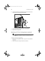
Connecting the VGA monitor
To connect the VGA monitor, simply plug the monitor cable into the
monitor/VGA port
system.
(blue port) located on the rear panel of your
AA G610.book Page 24 Monday, October 22, 2001 9:46 AM
24
2 System tour
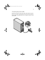
Connecting to the network
You can connect your computer to a Local Area Network (LAN) using a
network cable. To do so, simply plug the network cable into the
network port
(gray port) located on the rear panel of your system.
Note: Consult your operating system manual for information on
how to configure your network setup.
AA G610.book Page 25 Monday, October 22, 2001 9:46 AM
25
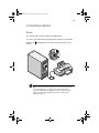
Connecting the power cable
Plug the power cable into the power cable socket located on the rear
panel of your system. Then plug the other end of the power cable into
a power outlet. The figure below shows a complete connection of the
whole system.
AA G610.book Page 26 Monday, October 22, 2001 9:46 AM
26
2 System tour
Turning on your system
After making sure that you have set up the system properly and
connected all the required cables, you can now power on your system.
To power on the system, press the power button on the front panel.
The system starts up and displays a welcome message. After that, a
series of power-on self-test (POST) messages appears. The POST
messages indicate if the system is running well or not.
Note: If the system does not turn on or boot after pressing the
power button, go to the next section for the possible causes of the
boot failure.
Aside from the POST messages, you can determine if the system is in
good condition by checking if the following occurred:
•
Power indicator on the front bezel lights up (green)
•
Num Lock, Caps Lock, and Scroll Lock indicators on the keyboard
light up
AA G610.book Page 27 Monday, October 22, 2001 9:46 AM
27
Power-on problems
If the system does not boot after you have applied power, check the
following factors that might have caused the boot failure.
•
The external power cable may be loosely connected.
Check the power cable connection from the power source to the
power cable socket on the rear panel. Make sure that the cable is
properly connected to the power source and to the power cable
socket.
•
No power comes from the grounded power outlet.
Have an electrician check your power outlet.
•
Loose or improperly connected internal power cables.
Check the internal cable connections. If you are not confident to
perform this step, ask a qualified technician to assist you.
Warning! Make sure all power cords are disconnected from
the electrical outlet before performing this task.
Note: If you have gone through the preceding actions and the
system still fails to boot, ask your dealer or a qualified technician
for assistance.
AA G610.book Page 28 Monday, October 22, 2001 9:46 AM
28
2 System tour
Turning off your system
To turn off your computer, on the Windows taskbar click on the Start
button, point to Shut Down..., select Shut down from the
drop-down window then click on OK. You can then turn off all
peripherals connected to your computer.
If you cannot shut down your computer, press the power button for at
least four seconds. Quickly pressing the button may put the computer
in a Suspend mode only.
AA G610.book Page 29 Monday, October 22, 2001 9:46 AM
29
Connecting options
Printer
Your system supports serial, parallel and USB printers.
To connect a parallel printer, plug the printer cable into the parallel/
printer port
system.
(burgundy port) located on the rear panel of your
Note: If you are using a serial printer, connect the printer cable
into either serial port 1 or serial port 2. In the same manner,
connect a USB printer by plugging the printer cable into either
USB ports. The serial and USB ports are both located on the
system’s rear panel.
AA G610.book Page 30 Monday, October 22, 2001 9:46 AM
30
2 System tour
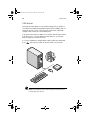
USB devices
Universal Serial Bus (USB) is a new serial bus design that is capable of
cascading low-/medium-speed peripherals (less than 12 Mbps) such as a
keyboard, mouse, joystick, scanner, printer and modem. With USB,
complex cable connections can be eliminated.
Your system comes with two USB ports located on the rear panel. These
ports allow you to connect additional serial devices to your system
without using up its system resources.
To connect a USB device, simply plug the device cable into either USB
ports
(black port) located on the rear panel of your system.
Note: Most USB devices have a built-in USB port which allows you
to daisy-chain other devices.
AA G610.book Page 31 Monday, October 22, 2001 9:46 AM
31
System rack installation
Observe the electrostatic discharge (ESD) precautions indicated on
page 49 when perfoming the following procedures.
Do not attempt the procedures described in the following sections
unless you are a qualified technician.
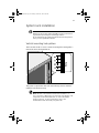
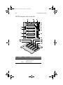
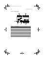
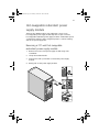
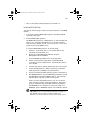
Vertical mounting hole pattern
The four vertical rails of a rack contain mounting holes arranged in a
manner shown in the figure below:
The system occupies 6U in the rack. Count the U positions and hole
numbers from the bottom up.
Note: The unit of measurement used in this document is "U"
(1U = 1.75 inches or 44.45 mm). The total sum of the heights of all
components in the rack measured in "U" cannot exceed the
height of the rack. For more information, refer to the
documentation that came with your system rack.
AA G610.book Page 32 Monday, October 22, 2001 9:46 AM
32
2 System tour
The distance from the center of two holes with closer spacing to the
center of the next pair is equivalent to 1U.
When installing components, you must start your measurement from
the center of the two holes with closer spacing. Otherwise, the screw
holes on the component may not match those on the rack.
Screw types used
The following screws are used in the assembly of the Acer Altos G610
and other rack-mountable components
Screw type and
part number
M4 x L5
Figure
Usage
86.6A536.8R0
Securing the component rails to
the tray
M4 x L8
86.6A536.8R0
Securing the mounting brackets
to the inner sliding piece
Washer
88.21341.605
Nut
87.11042.670
M5 x L5
Securing system components
M6 x L10
86.6A52A.100
Securing the cable carrier and
the mounting rails to the rack
Locating ring for
Rack 1024
34.94815.001
Supports the M6 metal screws
for securing server components
to Rack 1024
Locating ring for
Rack 1042
34.94814.001
Supports the M6 metal screws
for securing server components
to Rack 1042
AA G610.book Page 33 Monday, October 22, 2001 9:46 AM
33
Screw type and
part number
Figure
Cage nut
Usage
Supports the M6 metal screws
for securing server components
to the rack
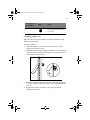
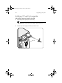
Installing cage nuts
Cage nuts are use to secure systems and other components to the
vertical rails in the rack.
To install cage nuts:
1
Insert the lower lip of the cage nut over the bottom of the
opening at the back of a rail.
2
Insert the small end of the cage-nut installation tool through the
opening in front of the rail and hook the tool over the top lip of
the cage nut as shown below.
3
Push in the cage nut while rotating the tool up and pulling the
tool back toward you until the top lip of the cage nut snaps into
position.
4
Repeat this process to install the other cage nuts in their
appropriate locations.
AA G610.book Page 34 Monday, October 22, 2001 9:46 AM
34
2 System tour
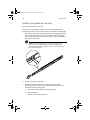
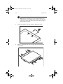
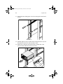
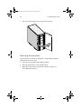
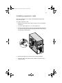
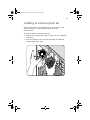
Installing the system into the rack
To install the system into the rack:
The rails allow the system to slide in and out of the rackmount for
maintenance purposes. Follow these steps to install the mounting rails:
1
Extend the component rail (1) from the mounting rail (2) until the
component rail release latch clicks. Hold down the latch and slip
the component rail out of the mounting rail. Do the same thing to
the other mounting rail.
Note: Each mounting rail consists of a fixed outer piece that
screws onto the mounting bracket and an inner sliding piece
controlled by a steel ball gearing movement. This inner sliding
piece is not detachable.
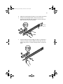
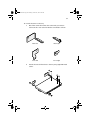
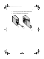
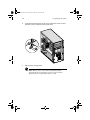
2
Put the component rails aside.
3
Attach the mounting brackets to the mounting rails. The
mounting brackets consist of two metal bars to be attached on
both ends of the mounting rails.
a
Unlock the inner sliding rail using your finger.
b
Push it forward.
c
Slide the roller towards the lock.
AA G610.book Page 35 Monday, October 22, 2001 9:46 AM
35
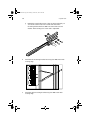
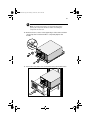
d
Adjust the inner sliding rail until you can see the screw holes.
e
Attach the mounting bracket to the front end of the
mounting rail and align the screw holes. Secure it with two
M4 x L8 screws with nut and washer.
f
Slide and adjust the inner sliding rail again to see the third
screw hole. Secure it with one M4 x L8 screw with nut and
washer. The position of the mounting bracket on this end is
fixed.
AA G610.book Page 36 Monday, October 22, 2001 9:46 AM
36
2 System tour
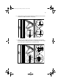
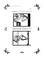
g
Extend the inner sliding piece of the mounting rail until you
can see the screw holes on the other end. Attach the
mounting bracket with two M4 x L8 screws with nut and
washer. The mounting rail on this end is adjustable.
4
Install the left mounting bracket first using four M6 screws with
locating rings.
5
Install the right mounting bracket using four M6 screws with
locating rings.
AA G610.book Page 37 Monday, October 22, 2001 9:46 AM
37
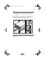
6
Secure the front side of the bracket first and then secure the rear
end with one M6 screw with locating ring.
7
Attach the cable carrier to the rack, overlapping the mounting
bracket, with two M6 screws without locating rings. Install a cage
nut on the topmost square hole to hold the screw.
AA G610.book Page 38 Monday, October 22, 2001 9:46 AM
38
2 System tour
Note: The cable carrier allows you to tie-wrap all cables to and
from the server. As you slide the server in and out of the rack, the
cable carrier collapses and extends, keeping the cables untangled
and attached to the server.
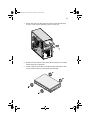
8
Attach the handle to the tray using two M5 metal screws.
9
Attach a component rail on each side of the tray with ten M4
metal screws.
AA G610.book Page 39 Monday, October 22, 2001 9:46 AM
39
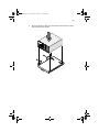
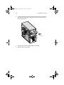
10 Install the server on the tray.
a
b
Check the stand-off brackets that came with your server’s
rackmount kit. Each stand-off bracket is marked as follows:
Rear left
Rear right
Front left
Front right
Attach the stand-off brackets to the tray using eight M5 metal
screws.
AA G610.book Page 40 Monday, October 22, 2001 9:46 AM
40
2 System tour
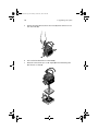
c
Remove the front panel door of the server. Refer to
“Removing the front panel door” on page 51 for instructions.
d
Remove the stands from the server. Keep the screws for later
use.
AA G610.book Page 41 Monday, October 22, 2001 9:46 AM
41
e
Place the server on the tray and secure it with the four screws
removed from the stands.
AA G610.book Page 42 Monday, October 22, 2001 9:46 AM
42
2 System tour
11 Extend the inner sliding piece of each mounting rail forward until
it clicks.
12 Carefully align the tray's rail with the mounting bracket's rail, and
then push the server into the rack until it clicks.
13 Depress the component rail release latch on either side of the
server and then slide the server into the rack.
AA G610.book Page 43 Monday, October 22, 2001 9:46 AM
43
Note: To avoid personal injury, care should be taken when
pressing the component rail release latches and sliding the
component into the rack.
14 Remove the two screws on the upper edge of the server and then
cut the clip that holds the handle to completely depress the
handle.
15 Attach the rack server cover to the server using the thumbscrews.
AA G610.book Page 44 Monday, October 22, 2001 9:46 AM
44
2 System tour
16 Attach the other end of the cable carrier to the tray using two M5
metal screws.
17 Extend the cable carrier to bundle all the cables to it using the
cable clamps. Route all cables from the cable carrier to the cable
management bracket located on the rear of the rack.
AA G610.book Page 45 Monday, October 22, 2001 9:46 AM
45
Note: For details on cabling and cable management bracket
installation, refer to the documentation that came with your
system rack.
18 Install two cage nuts on the upper left and right thumbscrews.
(The lower left and right thumbscrews do not need cage nuts.)
Secure the server to the rack using the thumbscrews.
Note: Refer to page 33 for instructions on how to install cage
nuts.
AA G610.book Page 46 Monday, October 22, 2001 9:46 AM
46
2 System tour
AA G610.book Page 47 Monday, October 22, 2001 9:46 AM
3 Upgrading your
system
AA G610.book Page 48 Monday, October 22, 2001 9:46 AM
This chapter contains basic information about
your system boards that you will find helpful
when performing the instructions of the
upgrade process which are also discussed in
this chapter.
AA G610.book Page 49 Monday, October 22, 2001 9:46 AM
49
Installation precautions
Before you install any system component, we recommend that you
read the following sections. These sections contain important ESD
precautions along with preinstallation and post-installation
instructions.
ESD precautions
Electrostatic discharge (ESD) can damage your processor, disk drives,
expansion boards, and other components. Always observe the
following precautions before you install a computer component:
1
Do not remove a component from its protective packaging until
you are ready to install it.
2
Wear a wrist grounding strap and attach it to a metal part of the
computer before handling components. If a wrist strap is not
available, maintain contact with the computer throughout any
procedure requiring ESD protection.
Preinstallation instructions
Always observe the following before you install any component:
1
Turn off your system and all the peripherals connected to it.
2
Unplug all cables from the power outlets.
3
Open your system according to the instructions on page 51.
4
Follow the ESD precautions described above when handling a
computer component.
5
Remove any expansion board(s) or peripheral(s) that block access
to the DIMM socket or other component connector.
See the following sections for specific installation instructions on the
component you want to install.
AA G610.book Page 50 Monday, October 22, 2001 9:46 AM
50
3 Upgrading your system
Warning! Failure to properly turn off the computer before
you start installing components may cause serious
damage.
Do not attempt the procedures described in the following
sections unless you are a qualified service technician.
Post-installation instructions
Observe the following after installing a computer component:
1
See to it that all components are installed according to the
described step-by-step instructions.
2
Replace any expansion board(s) or peripheral(s) that you have
previously removed.
3
Connect the necessary cables.
4
Replace the side panel.
5
Turn on the system.
AA G610.book Page 51 Monday, October 22, 2001 9:46 AM
51
Opening your system
Caution: Before you proceed, make sure that you have turned
off your system and all peripherals connected to it. Read the
“Preinstallation instructions” on page 49.
You need to open your system before you can install additional
components. The system housing has one front panel door and one
removable side panel. See the following section for instructions.
Opening the front panel door
A security lock secures the front panel door to protect your system unit
against unauthorized access.
To open the front panel door:
1
Insert the key into the lock and turn it clockwise until it points to
the unlocked icon .
2
Pull open the front panel door.
Removing the front panel door
The front panel door is attached to the main housing by screwless
hinges. Follow these steps to remove the door:
1
Unlock the door with the key (when necessary).
2
Open it to more than a 45° angle.
AA G610.book Page 52 Monday, October 22, 2001 9:46 AM
52
3
3 Upgrading your system
Lift it up a little, then move it away from the housing.
Removing the side panel
A microswitch is located on the side panel. It helps indicate whether
the panel is removed or intact.
1
Turn off your system unit and unplug all cables.
2
Place the system unit on a flat, steady surface.
3
Open then remove the front panel door. Refer to page 51 for
more detailed instructions.
AA G610.book Page 53 Monday, October 22, 2001 9:46 AM
53
4
Remove the two front screws with a Phillips screwdriver. Keep
them in a safe place for later use.
5
Pull out the panel handle to remove the side panel.
AA G610.book Page 54 Monday, October 22, 2001 9:46 AM
54
3 Upgrading your system
System boards
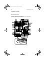
Mainboard layout
The mainboard becomes accessible once you open the system. It
should look like the figure shown below
AA G610.book Page 55 Monday, October 22, 2001 9:46 AM
55
Item
Description
BT1
Battery
BU1
Buzzer
CN1/CN6/CN36
IPMI connectors
CN3
ATX power supply connector
CN4
Upper: PS/2 mouse connector
Lower: PS/2 keyboard connector
CN5
Serial port connector
CN7
CPU 1 thermal connector
CN8
CPU 1 fan connector
CN9
RDN P.S. status connector
CN10
Upper: Parallel port
Lower left: Serial port 1
Lower right: Monitor/VGA port
CN13/CN19/
CN20/CN23/CN28
Housing fan connectors
CN14
USB1 and 2 connectors
CN15
LED/Switchboard connector (see page 57)
CN16
LAN Jack (RJ-45)
CN18
NMI switch
CN21
Primary IDE connector
CN22/CN31
BMC DB connectors
CN24
CPU 2 fan connector
CN25
CPU 2 thermal connector
CN29
Narrow SCSI channel B connector
AA G610.book Page 56 Monday, October 22, 2001 9:46 AM
56
3 Upgrading your system
Item
Description
CN32
Wide SCSI channel B connector
CN33/CN34
External hard disk drive LED connectors
CN35/CN38
Wide SCSI channel A connectors
CN37
Wake on LAN connector
CN40
Floppy disk drive connector
CN41
Event LED (HDD fail) connector
CN42
I2C connector
CN46
Speaker connector
CPU1
CPU 1 socket
CPU2
CPU 2 socket
DM1 to DM4
DIMM slots
JP5
Event clear connector
JP6
SCSI terminator
1-2: Disabled
2-3: On
JP7
Logo
1-2: Acer logo
2-3: OEM
JP8
Password settings
1-2 : Bypass password
2-3 : Check password
JP9
Speaker connector
JP10
CPU PST
1-2 : Terminator board
2-3 : CPU
P1 to P4
64-bit/33 MHz PCI slots
AA G610.book Page 57 Monday, October 22, 2001 9:46 AM
57
Item
Description
P5 and P6
32-bit/33 MHz PCI slots
U10
Server Works LE III CNB30LE chipset (north bridge)
U20
Intel 82559 LAN chipset
U21
ATI Rage XL video chipset
U85
Adaptec AIC-7899 chipset
U92
Server Works LE III OSB4 chipset (south bridge)
U93
BIOS chipset
U99
SMC 47B277 super I/O chipset
Settings in bolface are the default factory settings.
AA G610.book Page 58 Monday, October 22, 2001 9:46 AM
58
3 Upgrading your system
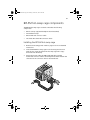
BPL5M jumpers and connectors
Label
Setting
Function
JP2
Short
Terminator power source both from
backplane and host
Open
Only from host
AA G610.book Page 59 Monday, October 22, 2001 9:46 AM
59
Label
Description
CN1
For SAF-TE card use
CN2
For SAF-TE card use (or for terminator board)
CN3
SCSI 68-pin connector
CN4
Front power LED connector
CN5
I2C buffer connector
JP1
I2C buffer ID setting
JP3
Power connectora
JP4
Power connector
JP5
3-pin FAN connector
S1
Slot 1 ID switchb
S2
Slot 2 ID switch
S3
Slot 3 ID switch
S4
Slot 4 ID switch
S5
Slot 5 ID switch
SLOT1
SCSI slot 1 connector
SLOT2
SCSI slot 2 connector
SLOT3
SCSI slot 3 connector
SLOT4
SCSI slot 4 connector
SLOT5
SCSI slot 5 connector
a. For the SCSI backplane board's loading requirement, please insert an independent
power cable to each power connector on the backplane board. The power cable
should not connect to any other device.
b. When you use the LVD SCSI hot-swap cage to arrange your system hard drives,
please remove all the jumpers on each SCSI hard drive and use the switches on the
backplane board (S1~S5) to set the hard drive's ID.
AA G610.book Page 60 Monday, October 22, 2001 9:46 AM
60
3 Upgrading your system
SAF-TE card layout
Label
Description
CN1
40-pin status connector for HDD backplane
CN2
68-pin SCSI connector for extended channel
CN3
68-pin SCSI connector for HDD backplane
SW1
Configuration switch
U7
GEM 318 SAF-TE chipset
U9
20 Mhz oscillator
AA G610.book Page 61 Monday, October 22, 2001 9:46 AM
61
BPL5M hot-swap cage components
The BPL5M hot-swap cage content box includes the following
components:
•
One hot-swap cage (with backplane board attached)
•
Five hard drive trays
•
One mainboard connector cable
•
Two hard drive fault LED connector cables
Installing the BPL5M hot-swap cage
1
Remove the housing panels. Refer to page 51 for more detailed
instructions.
2
Insert the BPL5M hot-swap cage into the housing and secure it
with the two screws provided. The hot-swap cage will occupy
three 5.25-inch drive bays.
3
Attach the power cable, the HDD fault LED cable, and the
mainboard connector cable to the backplane board and attach the
other end of the connector cable to the mainboard.
AA G610.book Page 62 Monday, October 22, 2001 9:46 AM
62
3 Upgrading your system
Note: Refer to “Mainboard layout” on page 54 for the location of
the SCSI connector.
4
Replace the housing panels.
System board connector cable
No.
Item
1
Connects to the mainboard
2
Blue strip with red edging
3
Connects to the hot-swap cage
Removing the BPL5M hot-swap cage
1
Remove the housing panels. Refer to page 51 for more detailed
instructions.
2
Remove the two screws that secure the hot-swap cage to the
housing.
AA G610.book Page 63 Monday, October 22, 2001 9:46 AM
63
3
Pull out the hot-swap cage from the housing.
Installing a hard disk into the BPL5M tray
1
Remove the BPL5M hot-swap cage from the housing. Refer to the
previous section for more detailed instructions.
AA G610.book Page 64 Monday, October 22, 2001 9:46 AM
64
3 Upgrading your system
2
Press your finger to the BPL5M hot-swap cage to release the drive
tray.
3
Remove the four tray screws to open the drive tray. Keep the
screws for later use.
4
When applicable, pull out any previously installed hard disk.
5
Install a hard disk on the drive tray then secure it with the four
tray screws you have removed earlier.
6
Insert the tray into the hot-swap cage with the lever still extended.
Make sure that the drive is properly inserted before closing the
lever.
7
Push the lever back until it clicks into place.
AA G610.book Page 65 Monday, October 22, 2001 9:46 AM
65
Installing and removing storage
devices
Your system supports one 3.5-inch and five 5.25-inch internal storage
devices. The empty drive bays allow you to install additional drives
such as a CD-ROM drive, a digital audio tape (DAT) drive or another
hard disk drive. These would provide your system additional storage
capacity.
Note: Your basic system already comes pre-installed with a
CD-ROM drive and a 3.5-inch floppy drive.
Replacing the 3.5-inch floppy drive
1
Remove the housing panels. Refer to page 51 for more detailed
instructions.
2
Disconnect the power and signal cables from the old drive.
3
Detach the old 3.5-inch drive with the drive frame from the
housing by removing the two chassis screws. Keep the screws for
later use.
4
Remove the four frame screws that hold the old drive to the drive
frame then pull out the drive.
5
Install a new 3.5-inch drive to the drive frame and secure it with
the four frame screws you have previously removed.
AA G610.book Page 66 Monday, October 22, 2001 9:46 AM
66
3 Upgrading your system
6
Insert the new drive into the drive bay and secure it with the two
chassis screws you have previously removed.
7
Connect the power and signal cables to the new drive.
8
Replace the housing panels.
Replacing a 5.25-inch storage device (optional)
Note: If you are installing a new drive in an empty drive bay, skip
steps 2 to 4.
To replace a 5.25-inch storage device:
1
Remove the housing panels. Refer to page 51 for more detailed
instructions.
2
Detach the power and signal cables from the drive.
AA G610.book Page 67 Monday, October 22, 2001 9:46 AM
67
3
Detach the 5.25-inch drive frame from the housing by removing
the two screws chassis. Keep the screws for later use.
4
Remove the four frame screws that hold the old drive to the drive
frame then pull out the drive.
5
Install a new 5.25-inch drive to the drive frame and secure it with
the four frame screws you have previously removed.
AA G610.book Page 68 Monday, October 22, 2001 9:46 AM
68
3 Upgrading your system
6
Insert the drive frame with the newly-installed 5.25-inch drive into
the drive bay and secure it with the two chassis screws you have
previously removed.
7
Connect the power and signal cables to the drive.
8
Replace the housing panels.
AA G610.book Page 69 Monday, October 22, 2001 9:46 AM
69
Removing and installing the CPU
Your system’s Pentium III processor comes in a FC-PGA 370-pin package.
The FC-PGA package is designed for the new breed of sleek, high
performance, small form factor PCs.
Your mainboard supports two Pentium III processors running at
933 Mhz and 1 GHz or two Intel Pentium III processors running at 512K
1.13- and 1.26 GHz and future generations of Pentium III processors on
a 100 or 133 MHz system bus.
Caution: Always observe the ESD precautions when installing or
removing a system component. Refer to page 49.
Removing a CPU
Follow these steps to remove a CPU:
1
Remove the housing panels. See page 51 for more detailed
instructions.
2
Locate the CPU socket on the mainboard.
3
Detach the fan/heatsink cable connector (1and 2).
4
Insert a flat screwdriver into the fan/heatsink metal bracket (3)
and pry it outward (4).
AA G610.book Page 70 Monday, October 22, 2001 9:46 AM
70
3 Upgrading your system
5
Detach the metal bracket from the socket (5) then remove it from
the other side (6).
6
Pull out the fan/heatsink from the CPU(1).
7
Raise the socket lever up to a 90° angle (2) before detaching the
CPU from its socket (3).
AA G610.book Page 71 Monday, October 22, 2001 9:46 AM
71
Caution: The heatsink becomes very hot when the system is on.
NEVER touch the heatsink with any metal or with your hands.
Installing a CPU
Before you proceed make sure that there is no CPU installed in the CPU
socket. Follow the steps below to install a CPU:
1
Locate the CPU socket on the mainboard.
2
Secure the CPU fan to its base with the four screws provided.
AA G610.book Page 72 Monday, October 22, 2001 9:46 AM
72
3 Upgrading your system
3
Align the CPU to its socket, making sure that pin 1 (indicated by
the notched corner) of the CPU connects to hole 1 of the socket
(on the bottom right corner) (1).
4
Insert the CPU into the socket (2), then press down the socket lever
to lock the CPU into place (3).
5
Reattach the metal bracket to the CPU (1 to 3), then plug the fan/
heatsink cable into the fan connector on the mainboard (4 and 5).
AA G610.book Page 73 Monday, October 22, 2001 9:46 AM
73
Removing and installing memory
modules
The four DIMM sockets onboard support 1024-MB registered SDRAM
DIMMs for a maximum memory capacity of 4 GB.
Note: The registered SDRAM module should work under 3.3 volts;
5-volt memory devices are not supported.
For data integrity, the default setting of the ECC (error correcting code)
function of the memory system in BIOS is enabled. Refer to “IPMI
Configuration” on page 107 for more information on this BIOS
parameter.
Note: The system board supports both 100 and 133 MHz
registered SDRAMs; 66 MHz SDRAMs are not supported.
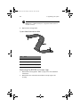
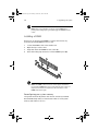
Removing a DIMM
Before you can install a new DIMM in a socket, remove first any
previously installed DIMM from that socket.
1
Remove the housing panels. Refer to page 51 for more detailed
instructions.
2
Locate the DIMM socket on the mainboard.
3
Press the holding clips on both sides of the socket outward to
release the DIMM (a).
4
Gently pull the DIMM upward to remove it from the socket (b).
AA G610.book Page 74 Monday, October 22, 2001 9:46 AM
74
3 Upgrading your system
Note: Place your forefingers on the top of the DIMM before
pressing the holding clips to gently disengage the DIMM from the
socket.
Installing a DIMM
Before you can install a new DIMM in a socket, remove first any
previously installed DIMM from that socket.
1
Locate the DIMM socket on the mainboard.
2
Open the clips on the socket.
3
Align then insert the DIMM into the socket (a).
4
Press the holding clips inward to lock the DIMM in place (b).
Note: The DIMM socket is slotted to ensure proper installation.
If you insert a DIMM but it does not fit easily into the socket, you
may have inserted incorrectly. Reverse the orientation of the
DIMM and insert it again.
Reconfiguring your system memory
The system automatically detects the amount of memory installed.
Run the BIOS Setup utility to view the new value for total system
memory and make a note of it.
AA G610.book Page 75 Monday, October 22, 2001 9:46 AM
75
Installing expansion cards
The onboard expansion slots supports PCI (Peripheral Component
Interconnect) cards.
To install an expansion card:
1
Remove the housing panels. Refer to page 51 for more detailed
instructions.
2
Locate an empty expansion slot on the mainboard.
3
Remove the metal bracket opposite the selected empty expansion
slot by removing the screw that holds the bracket to the housing
then pulling out the bracket.
4
Remove the expansion card from its protective packaging.
5
Align the card in the empty bracket. Make sure that the card is
properly seated.
AA G610.book Page 76 Monday, October 22, 2001 9:46 AM
76
3 Upgrading your system
6
Insert the bracket with the card into the selected slot then secure it
with the screw you have previously removed.
7
Replace the housing panels.
Note: When you turn on the system, the BIOS Setup utility
automatically detects and assigns resources to the new device
(applicable only to Plug-and-Play expansion cards).
AA G610.book Page 77 Monday, October 22, 2001 9:46 AM
77
Hot-swappable redundant power
supply module
The Acer Altos G610 model’s power subsystem consists of two
hot-swappable power supply module bays that accepts 337-watt
hot-swappable redundant power supply modules. A redundant power
configuration enables a fully-configured system to continue running
even if one power supply fails.
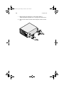
Removing a 337-watt hot-swappable
redundant power supply module
1
Remove the screw of the power supply module using a flat
screwdriver.
2
Lift up the module handle.
3
Push the lock with your thumb to release the power supply
module.
4
Gently pull out the power supply module.
AA G610.book Page 78 Monday, October 22, 2001 9:46 AM
78
3 Upgrading your system
Installing a 337-watts hot-swappable
redundant power supply module
1
Insert the power supply into the housing.
Note: Make sure that the power supply is properly inserted.
2
Secure the power supply with the provided screw.
AA G610.book Page 79 Monday, October 22, 2001 9:46 AM
79
Installing an internal system fan
An internal system fan can be installed to allow the system to still
operate properly in case the default internal system fan
malfunctioned.
To install an additional internal system fan:
1
Remove the housing panels. Refer to page 51 for more detailed
instructions.
2
Press the system fan latch outward, then insert the additional
internal system fan in place.
AA G610.book Page 80 Monday, October 22, 2001 9:46 AM
80
3 Upgrading your system
AA G610.book Page 81 Monday, October 22, 2001 9:46 AM
4 BIOS Setup
utility
AA G610.book Page 82 Monday, October 22, 2001 9:46 AM
This chapter gives information about the
system BIOS and discusses how to configure
the system by changing the settings of the
BIOS parameters.
AA G610.book Page 83 Monday, October 22, 2001 9:46 AM
83
BIOS Setup utility
The BIOS Setup utility is a hardware configuration program built into
your computer's Basic Input/Output System (BIOS). Since most
computers are already properly configured and optimized, there is no
need to run this utility. However, if you encounter configuration
problems and get the "Run Setup" message, you will need to run this
utility.
The Setup program loads the configuration values in a battery-backed
nonvolatile memory called CMOS RAM. This memory area is not part
of the system RAM which allows configuration data to be retained
when power is turned off.
Note: If you repeatedly receive Run Setup messages, the battery
may be bad. In this case, the system cannot retain configuration
values in CMOS. Ask a qualified technician for assistance.
Before you run Setup, make sure that you have saved all open files.
The system reboots immediately after you exit Setup.
AA G610.book Page 84 Monday, October 22, 2001 9:46 AM
84
4 BIOS Setup utility
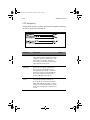
Entering Setup
Power on the computer to start the system POST (Power On Self Test)
process. While booting, press the key combination Ctrl+Alt+Esc
simultaneously.
The Basic Setup Utility main menu will appear.
Note: You must press Ctrl+Alt+Esc while the system is booting.
This key combination does not work during any other time.
The system supports two Setup Utility levels: Basic and Advanced.
If you are an advanced user, you may want to check the detailed
configuration of your system. Detailed system configurations are
contained in the Advanced Level. To view the Advanced Level, press F8
while viewing the Basic Setup main menu.
The Key Help Guide (press <Alt+H> to activate) shows you how to
move around the BIOS setup screen:
•
Use the Up and Down arrow keys to move around the Setup
Utility screen.
•
Use the Left and Right arrow keys to move to the next page or to
return to the previous page if the setup screen has more than one
page available.
•
Use the Page Up, Page Down, +, or - keys to select the options if
they are available.
•
Press Esc to return to the Main menu.
Note: The parameters on the screens shown in this User’s guide
display default system values. These values may not be the same as
those in your computer. The grayed-out items on the screens have
fixed settings and are not user-configurable.
AA G610.book Page 85 Monday, October 22, 2001 9:46 AM
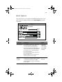
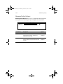
85
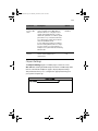
Basic Setup Utility main menu
Advanced Setup Utility main menu
In the descriptive table following each of the main menu option
screens:
•
An asterisk (*) mark indicates that the parameter appears only
when you are in the Advanced Level.
•
The settings in boldface are the default and suggested parameter
settings.
AA G610.book Page 86 Monday, October 22, 2001 9:46 AM
86
4 BIOS Setup utility
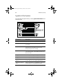
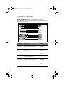
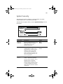
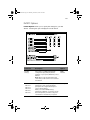
System Information
The screen below appears when you select System Information from
the main menu:
Parameter
Description
Processor
Type of processor currently installed in your system
Processor Speed
Clock speed of the processor currently installed in
your system
Level 1 Cache
Total amount of first-level cache memory or the
internal fast accessed memory size (i.e., the
memory integrated into the CPU)
Level 2 Cache
Total amount of second-level cache memory that
comes with the CPU. The available cache sizes are
256 and 512 KB.
Floppy Drive A
Current system settings for floppy drive A
Floppy Drive B
Current system settings for floppy drive B
IDE Primary Channel
Master
Current configuration of the IDE device connected
to the master port of the primary IDE channel
IDE Primary Channel
Slave
Current configuration of the IDE device connected
to the slave port of the primary IDE channel
AA G610.book Page 87 Monday, October 22, 2001 9:46 AM
87
Parameter
Description
Total Memory
Total amount of onboard memory. The memory
size is automatically detected by BIOS during the
POST. If you install additional memory, the system
automatically adjusts this parameter to display the
new memory size.
1st Bank
2nd Bank
3rd Bank
Type and size of DIMM installed in DIMM sockets 1,
2, 3 and, 4 respectively. The None setting indicates
that there is no DIMM installed.
4th Bank
Serial Port 1
Serial port 1 address and IRQ setting
Serial Port 2
Serial port 2 address and IRQ setting
Parallel Port
Parallel port address and IRQ setting
PS/2 Mouse
Pointing device installation setting. Displays None
if no pointing device is installed.
AA G610.book Page 88 Monday, October 22, 2001 9:46 AM
88
4 BIOS Setup utility
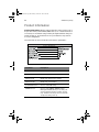
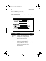
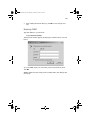
Product Information
Product Information displays general data about the system, such as
the product name, serial number, BIOS version, etc. These information
is necessary for troubleshooting and may be required when asking for
technical support. These entries are for your reference only and are
not user-configurable.
The screen below shows the Product Information parameters:
Parameter
Description
Product Name
Official name of the system
System S/N
System’s serial number
Mainboard ID
Mainboard’s identification number
Mainboard S/N
Mainboard’s serial number
System BIOS Version
Version of the BIOS utility
SMBIOS Version
Version of the SMBIOS. SMBIOS (System
Management BIOS) allows you to check your
system’s hardware without actually opening
it up. Hardware checking is done via software
checkpoints during start up.
AA G610.book Page 89 Monday, October 22, 2001 9:46 AM
89
Disk Drives
Select Disk Drives to input configuration values for the system disk
drives. The screen below shows the Disk Drives screen:
Parameter
Description
Option
Floppy Drive A
Indicates the floppy disk drive
type
1.44 MB, 3.5-inch
None
360 KB, 5.25-inch
1.2 MB, 5.25-inch
720 KB, 3.5-inch
2.88 MB, 3.5-inch
IDE Primary
Channel Master
These items let you select the IDE
hard disk parameters that your
system supports.
IDE Primary
Channel Slave
Auto. Enables BIOS to
automatically detect the
parameters of installed HDDs
during the POST (power-on
self-test).
User. HDD parameters manually
configured.
None. No HDD is connected to the
system.
Note: The IDE CD-ROM is always
automatically detected.
AA G610.book Page 90 Monday, October 22, 2001 9:46 AM
90
4 BIOS Setup utility
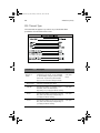
IDE Channel Type
The screen below appears if you select any of the the IDE drive
parameters from the Disk Drives screen:
Parameter
Description
Option
Device
Detection
Mode
Lets you specify the type of hard disk
installed in your system. If you want BIOS
to automatically configure your hard disk,
select Auto. If you know your hard disk
type, you can enter the setting manually.
Auto
User input
None
Device Type
Indicates a hard disk type device
Cylinder
Specifies the number of cylinders in your
hard disk, and is automatically set
depending on your Type parameter setting.
User input
Head
Specifies the number of heads in your hard
disk, and is automatically set depending on
your Type parameter setting.
User input
Sector
Specifies the number of sectors in your hard
disk, and is automatically set depending on
your Type parameter setting.
User input
AA G610.book Page 91 Monday, October 22, 2001 9:46 AM
91
Parameter
Description
Option
Specifies the size of your hard disk, in MB
User input
Hard Disk LBA
Mode *
When set to Auto, the BIOS utility
automatically detects if the installed hard
disk supports the function. If supported, it
allows you to use a hard disk with a
capacity of more than 528 MB. This is made
possible through the Logical Block Address
(LBA) mode translation. However, this
enhanced IDE feature works only under
DOS, Windows 3.x, Windows 95, Windows
98, Windows NT 3.5 and above, and
Windows 2000. Other operating systems
require this parameter to be set to
Disabled.
Auto
Disabled
Hard Disk
Block Mode *
Enhances disk performance depending on
the hard disk in use. If you set this
parameter to Auto, the BIOS utility
automatically detects if the installed hard
disk drive suports the Block Mode function.
If supported, it allows data transfer in
blocks (multiple sectors) at a rate of
256 bytes per cycle.
Auto
Disabled
Hard Disk
32-bit Access *
Improves system performance by allowing
the use of the 32-bit hard disk access. This
enhanced IDE feature works only under
DOS, Windows 3.x, Windows 95, Windows
98, Windows NT, Windows 2000, and Novell
Netware. If your software or hard disk
does not support this function, set this
parameter to Disabled.
Enabled
Disabled
Advanced PIO
Mode *
When set to Auto, the BIOS utility
automatically detects if the installed hard
disk supports the function. If supported, it
allows for faster data recovery and read/
write timing that reduces hard disk activity
time. This results in better hard disk
performance. To disregard the feature,
change the setting to Disabled.
Enabled
Size
Auto
Mode 0
Mode 1
Mode 2
Mode 3
Mode 4
Disabled
AA G610.book Page 92 Monday, October 22, 2001 9:46 AM
92
4 BIOS Setup utility
Parameter
Description
Option
DMA
Transfer
Mode *
The Ultra DMA and Multi-DMA modes
enhance hard disk performance by
increasing the transfer rate. However,
besides enabling these features in the BIOS
Setup, both the Ultra DMA and Multi-DMA
modes require the DMA driver to be
loaded.
Enabled
Auto
Multiword
Mode 0
Mode 1
Mode 2
Disabled
AA G610.book Page 93 Monday, October 22, 2001 9:46 AM
93
Onboard Peripherals
Onboard Peripherals allows you to configure the onboard
communication ports and the onboard devices. Selecting this option
displays the screen below:
Parameter
Description
Option
Serial Port 1
Enables or disables serial port 1
Enabled
Disabled
Base Address
Sets the I/O base address of
serial port 1
3F8h
2F8h
3E8h
2E8h
IRQ
Sets the IRQ (interrupt request)
channel of serial port 1
4
Serial Port 2
Enables or disables serial port 2
Disabled
Enabled
Base Address
Sets the serial port 2 I/O base address
2F8h
3E8h
2E8h
11
AA G610.book Page 94 Monday, October 22, 2001 9:46 AM
94
4 BIOS Setup utility
Parameter
Description
Option
IRQ
Sets the IRQ channel of serial port 2
3
10
Parallel Port
Enables or disables the parallel port
Enabled
Disabled
Base Address
Sets a logical base address for the
parallel port. This parameter is
configurable only if the Parallel Port
parameter is enabled.
378h
278h
IRQ
Assigns an interrupt for the parallel
port. This parameter is configurable
only if the Parallel Port parameter is
enabled.
If you install an add-on card that has
a parallel port whose address conflicts
with the onboard parallel port, a
warning appears on the screen.
Check the parallel port address of the
add-on card and change the address
to one that does not conflict.
7
5
Operation
Mode
Sets your parallel port’s operation
mode. This parameter is configurable
only if the Parallel Port parameter is
enabled.
Enhanced
Parallel Port
(EPP)
Bi-directional
Extended
Capabilities Port
(ECP)
Standard Parallel
Port (SPP)
ECP DMA
Channel
Assigns a DMA channel for the ECP
parallel port function. This
parameter is configurable only if you
select the Extended Capabilities Port
(ECP) as the operation mode.
Floppy Disk
Controller
Enables or disables the onboard
floppy disk controller
Enabled
Disabled
AA G610.book Page 95 Monday, October 22, 2001 9:46 AM
95
Parameter
Description
Option
IDE
Controller
Enables or disables the onboard
primary, secondary or both IDE
interfaces
Both
PS/2 Mouse
Controller
Enables or disables the onboard PS/2
mouse controller
Enabled
Disabled
USB Host
Controller
Enables or disables the onboard USB
host controller
Enabled
Disabled
USB Legacy
Mode
Activates or deactivates the USB
keyboard connected to your system.
When activated, the USB keyboard
functions in a DOS environment.
Disabled
Enabled
Onboard SCSI
Enables or disables the onboard SCSI
controller
Enabled
Enables or disables the onboard
Ethernet controller
Enabled
Disabled
Onboard
Ethernet Chip
Primary
Secondary
Disabled
Disabled
AA G610.book Page 96 Monday, October 22, 2001 9:46 AM
96
4 BIOS Setup utility
Power Management
The Power Management menu allows you to configure the system’s
power management feature.
The screen below shows the parameters on the Power Management
screen:
Parameter
Description
Option
Power
Management
Mode
Allows you to reduce power
consumption. When this parameter is set
to Enabled, you can configure the IDE hard
disk and system timers. Setting it to
Disabled deactivates the powermanagement feature and its timers.
Enabled
IDE Hard Disk
Standby Timer
Allows the hard disk to enter standby
mode after inactivity of 1 to 15 minutes,
depending on your setting. When you
access the hard disk again, allow 3 to 5
seconds (depending on the hard disk) for
the disk to return to normal speed. Set this
parameter to Off if your hard disk does not
support this function.
Off
1 minute to
Disabled
15 minutes
AA G610.book Page 97 Monday, October 22, 2001 9:46 AM
97
Parameter
System Sleep
Timer
Sleep Mode
Description
Option
This parameter sets the system to the
lowest power-saving mode after a
specified period of inactivity. Any
keyboard or mouse action or any activity
detected from the IRQ channels resumes
system operation.
Off
Lets you specify the power-saving mode
that the system will enter after a specified
period of inactivity.
Standby
1 minute to
120 minutes
Suspend
This parameter becomes configurable only
if the System Sleep Timer is on. Any
keyboard or mouse action, or any enabled
monitored activities occurring through the
IRQ channels resume system operation.
Power Switch
< 4 sec.
When set to Power off, the system
automatically turns off when the power
switch is pressed for less than 4 seconds.
When set to Suspend, the system enters
the suspend mode when the power switch
is pressed for less than 4 seconds.
System
Wake-up
Event
The system wake-up event allows the
system to resume operation when the
modem ring indicator is enabled.
Power off
Suspend
Modem Ring
Indicator
When Enabled, any fax/modem activity
wakes up the system from suspend mode.
Disabled
Enabled
PCI Power
Management
Enables or disabled the PCI power
managment function
Enabled
RTC Alarm
Allows you to set a certain time on a
certain day to wake-up your system from
suspend mode.
Disabled
Resume
Day
If RTC alarm is enabled, the system will
resume operation on the day indicated
here.
User input
Resume
Time
If RTC alarm is enabled, the system will
resume operation at the time indicated
here.
User input
Disabled
Time
Date/Time
AA G610.book Page 98 Monday, October 22, 2001 9:46 AM
98
4 BIOS Setup utility
Parameter
Description
Option
Restart on AC
Power Failure
When a power failure occurs and this item
is set to Pre-state, the system will be turned
on, when the power comes back, if the
system was on.
When a power failure occurs and this
setting is disabled, the system remains off
when the power comes back, even if the
system was on before the power failure
occurs..
Pre-state
Disabled
AA G610.book Page 99 Monday, October 22, 2001 9:46 AM
99
Boot Options
This option allows you to specify your preferred settings for boot up.
The screen below appears when you select Boot Options from the
main menu:
Parameter
Description
Option
Boot Sequence
This parameter allows you to specify the
boot search sequence during POST.
Floppy Disk
LANDesk (R)
Service Agent
1st. The system checks this drive first.
2nd. The system then checks this drive if it
can not boot from the 1st specified drive.
IDE CD-ROM
Hard DIsk
3rd. If the first two searches fail then it
boots from this drive.
4th. If the first three searches fail then it
boots from this drive.
BIOS will display an error message if the
drive(s) specified is not bootable.
Primary
Display
Adapter
Lets you activate the onboard video
controller as your primary display adapter,
or automatically disable it once BIOS
detects that there is a video card installed
in your system.
Auto
Onboard
AA G610.book Page 100 Monday, October 22, 2001 9:46 AM
100
4 BIOS Setup utility
Parameter
Description
Option
Fast Boot
Allows the system to boot faster by
skipping some POST routines
Auto
Disabled
Silent Boot
Enables or disables the Silent Boot
function. When set to Enabled, BIOS is in
graphical mode and displays only an
identification logo during POST and while
booting. After booting the screen displays
the operating system prompt (such as DOS)
or logo (such as Windows 95). If any error
occurs while booting, the system
automatically switches to text mode.
Enabled
Disabled
Even if your setting is Enabled, you may
still switch to text mode while booting by
pressing the Delete key when you see the
"Press DELETE key to enter setup" message
on the screen.
When set to Disabled, BIOS is in the
conventional text mode where you see the
system initialization details on the screen.
Num Lock
After Boot
Allows you to activate the Num Lock
function upon booting
Disabled
Memory Test
When set to Enabled, this parameter
allows the system to perform a RAM test
during the POST routine. When set to
Disabled, the system detects only the
memory size and bypasses the test routine.
Disabled
Release All
Blocked
Memory
When set to Enabled, this parameter
allows the system to bypass testing the
defective memory banks detected earlier.
Disabled
Enabled
Boot from
LANDesk (R)
Service Agent
When set to Enabled, the system boots
from a LANDesk Service Agent network
instead of your desktop system. The
LANDesk Service Agent is a IEEE-standardsbased code that intervenes in the boot
process. Refer to your LANDesk Manual for
more information.
When set to Disabled, the system boots
from the drive specified in the Boot
Sequence parameter.
Disabled
Enabled
Enabled
Enabled
AA G610.book Page 101 Monday, October 22, 2001 9:46 AM
101
Parameter
Description
Option
Update BIOS
with Boot
Block
When enabled, it automatically flashes the
BIOS file from the hard disk drive in case
the system fails to boot up
Disabled
Enabled
Configuration
Table *
Displays preboot system configuration
table when enabled
Enabled
Disabled
POST Error
Stop *
When enabled, if the POST finds an error,
it will stop and the user has to press F1 to
continue. If disabled, even when the POST
finds an error, it will not stop.
Enabled
Disabled
AA G610.book Page 102 Monday, October 22, 2001 9:46 AM
102
4 BIOS Setup utility
Date and Time
The real-time clock keeps the system date and time. After setting the
date and time, you do not need to enter them every time you turn on
the system. As long as the internal battery remains good
(approximately seven years) and connected, the clock continues to
keep the date and time accurately even when the power is off.
Parameter
Description
Date
Set the date following the weekday-month-day-year
format. Valid values for weekday, month, day, and year
are:
Weekday: Sun, Mon, Tue, Wed, Thu, Fri, Sat
Month: Jan, Feb, Mar, Apr, May, Jun, Jul, Aug, Sep, Oct,
Nov, Dec
Day: 1 to 31
Year: 1980 to 2079
Time
Set the time following the hour-minute-second format.
Valid values for hour, minute, and second are:
Hour: 00 to 23
Minute: 00 to 59
Second: 00 to 59
AA G610.book Page 103 Monday, October 22, 2001 9:46 AM
103
System Security
The Setup program has a number of security features to prevent
unauthorized access to the system and its data.
Thescreen below appears when you select System Security from the
main menu:
Parameter
Description
Option
Supervisor
Password
Prevents unauthorized access to the
BIOS Setup utility. The Present
setting allows you to set a
Supervisor password.
None
Present
User Password
Secures your system against
unauthorized use. Once you set
this password, you have to type it
whenever you boot the system.
User password is available only
when a Supervisor password is set.
The Present settings allows you to
set a User password.
None
Present
Disk Drive
Control
The disk drive control features
enable or disable the read/write
functions of the disk drives. These
features can also control the
diskette drive boot function to
prevent loading operating systems
or other programs from a certain
drive while the other drives remain
operational.
AA G610.book Page 104 Monday, October 22, 2001 9:46 AM
104
Parameter
Floppy Drive
4 BIOS Setup utility
Description
Option
Sets the control level of the floppy
drive
Normal
Write Protect All
Sectors
Write Protect Boot
Sectors
Disabled
Hard Disk
Drive
Sets thecontrol level of the IDE
drive
Normal
Write Protect All
Sectors
Write Protect Boot
Sectors
Disabled
Processor
Serial Number
The Pentium III processor
incorporates an individual serial
number in each chip that can
identify individual CPUs. When
enabled, CPUs can be identified by
its processor serial number. Disable
this parameter to deactivate this
feature.
Enabled
Disabled
AA G610.book Page 105 Monday, October 22, 2001 9:46 AM
105
Setting and changing the password
To set or change a Supervisor/User password:
1
Enable the Supervisor Password or User Password parameter in the
System Security menu by pressing the Up or Down arrow key to
select Present. The corresponding password window appears:
Supervisor Password window
User Password window
2
Type a password then press Enter. The password may consist of up
to seven alphanumeric characters.
Note: Be careful when typing your password because the actual
characters do not appear on the screen; password characters
appear as asterisks (*).
3
Retype the password to verify your first entry then press Enter.
4
Highlight the “Set or Change Password” option then press
Enter.
5
Press Esc to return to the System Security screen.
6
Press Esc to exit Setup. The Exit Setup screen appears.
7
Choose “Yes” to save your settings and exit Setup. Your password
will be saved to CMOS.
AA G610.book Page 106 Monday, October 22, 2001 9:46 AM
106
4 BIOS Setup utility
Removing a password
To remove your Supervisor/User password:
1
Disable the Supervisor Password or User Password parameter in
the System Security menu by pressing the up or down arrow key
to select None.
2
Press Esc to return to the System Security menu.
3
Press Esc to exit Setup. The Exit Setup screen appears:
4
Choose Yes to save your settings and exit Setup. Your previous
password will be removed from CMOS.
AA G610.book Page 107 Monday, October 22, 2001 9:46 AM
107
IPMI Configuration
Intelligent Platform Management Interface
The system event log enables you to record and monitor events that
occur in your system like system temperature changes, fan stops, and
others. This feature also allows you to specify the appropriate settings
for your system’s event handling.
The table below describes the parameters in the IPMI Configuration
screen.
Parameter
Description
IPMI
Specification
Version
Specifies the version of Intelligent Platform
Management Interface (IPMI)
Option
AA G610.book Page 108 Monday, October 22, 2001 9:46 AM
108
4 BIOS Setup utility
Parameter
Description
Option
IPMI BIOS
Version
Shows the version of IPMI BIOS
BMC
Firmware
Version
Specifies the version of BaseBoard
Management Controller (BMC) Firmware
System Event
Logging
Enables or disables the event logging
function of your system
Enabled
Clear Event
Log Area
Clears the event log whenever the event
log area is full
Disabled
Enabled
Existing Event
Log Number
Number of events currently located in the
event log area
Remaining
Event Log
Number
Number of spaces that are still available
for logging system events
View Event
Logs
Opens the system event log file for viewing
Disabled
Event Control
BIOS POST
BIOS checks the bad processors and
memory modules during POST. When this
parameter is enabled, BIOS will stop POST
operation whenever it finds a bad
processor or memory. Otherwise, if
disabled the system will continue running.
Enabled
Disabled
Memory ECC
ECC (error correcting code) tests the
accuracy of data as it passes in and out of
memory. This parameter enables or
disables the monitoring of this function.
Enabled
PCI (Peripheral Component Interconnect) is
a 32-bit bus that supports a 64-bit
extension for new processors, such as
Pentium processors. It can run at clock
speeds of 33 or 66 MHz. This parameter
monitors the activity of this bus when set
to Enabled.
Enabled
Disabled
PCI Devices
Disabled
AA G610.book Page 109 Monday, October 22, 2001 9:46 AM
109
RDM Configuration
Remote Data Management
Parameter
Description
RDM 4.5 BIOS
Version
Shows the version number of the RDM
BIOS
Option
AA G610.book Page 110 Monday, October 22, 2001 9:46 AM
110
4 BIOS Setup utility
Parameter
Description
Option
Console
Redirection
This parameter lets you enable or disable
the connection to the RDM manager
station. If enabled and conditions are met,
the RDM-enabled server automatically
dials the RDM manager station using the
phone number specified in the Remote
Console Phone No. parameter when the
server reboots. Once the connection is
established, both the RDM server and RDM
manager station display the same screen
which enables the RDM manager station to
function the same as the server console.
Setting this to Disabled deactivates the
RDM manager station.
Disabled
Enabled
Hidden
Partition
If you want the hidden partition to
become accessible, set this parameter to
Enabled. When enabled, the server boots
to the hidden partition.
Disabled
Communication
Protocol
This parameter specifies the parity, stop
bits, and data length for the COM port to
use for the RDM connection. This is fixed
at N (none), 8, 1 setting and is
non-configurable.
N, 8, 1
COM Port Baud
Rate
This parameter lets you set the transfer
rate of the COM for the RDM connection.
The parameter setting depends on your
modem specification; therefore, before
you change the setting of this parameter,
check the documentation that came with
your modem.
9600
Enabled
57600
AA G610.book Page 111 Monday, October 22, 2001 9:46 AM
111
Parameter
Description
Option
Remote Console
Phone No.
This parameter allows you to set the phone
number of the RDM manager station that
the RDM module must dial once RDM is
activated and the Remote Console is
enabled. To set, simply highlight the
parameter and enter the Remote Console
phone number.
User input
If the remote console phone number is
using an (X) line, then you must enter six
commas (,) after the phone number and
before the extension number, if any.
When entering the extension number, we
recommend that you insert a comma after
each number. The commas specify delay.
If this parameter is left blank, the Remote
Console calling function is disregarded.
Dial Out Retry
Times
This parameter lets you specify the
maximum number of times the RDM server
must retry to connect to the RDM manager
station once the server fails and RDM is
activated. If the server has completed the
specified number of tries and the
connection still fails, the server bypasses
RDM and goes into normal mode.
2
4
8
Infinite
Emergency Management
RDM Work
Mode
When detecting system failure, the RDM
module will take some actions according to
the enabled mode.
Waiting: Page and wait for the RDM
station to call in
Reboot: Page, then reboot
Disabled
Waiting
Reboot
Disabled: No action
Note: If Waiting is selected, a password
consisting of at least three alphanumeric
characters must be set.
Waiting Mode
Password
Prevents unauthorized access to the server
User input
AA G610.book Page 112 Monday, October 22, 2001 9:46 AM
112
4 BIOS Setup utility
Parameter
Description
Option
Paging Times
Allows you to set the number of times that
the RDM module must dial when the
server fails or hangs
1
Allows you to set the pager number that
the RDM module must dial when the
server fails or hangs
User input
Paging No.
2
4
8
AA G610.book Page 113 Monday, October 22, 2001 9:46 AM
113
Advanced Options
Note: To avoid damaging the system, do not change any settings
in the Advanced Options submenus unless you are a qualified
technician.
The Advanced Options screen allows you to configure the system
memory, PCI device settings, CPU frequency and chipset settings.
The screen below shows the Advanced Options parameters:
AA G610.book Page 114 Monday, October 22, 2001 9:46 AM
114
4 BIOS Setup utility
Memory/Cache Options
Memory/Cache Options allows you to configure the advanced system
memory functions. Selecting this option displays the screen below:
Parameter
Description
Option
Level 1 Cache
Enables or disables the first-level or
internal memory, that is, the memory
integrated into the CPU.
Enabled
Enables or disables the second-level cache
memory which is incorporated in the CPU
module.
Enabled
Level 2 Cache
Disabled
Disabled
AA G610.book Page 115 Monday, October 22, 2001 9:46 AM
115
PnP/PCI Options
PnP/PCI Options allows you to specify the settings for your PCI
devices. Selecting this option displays the screen below:
Parameter
Description
Option
PCI IRQ
Setting
Select Auto to let BIOS automatically
configure the plug-and-play devices
installed on your system; Otherwise, select
Manual.
Auto
Manual
Note: Refer to the documentation that
came with your PCI card for more technical
information.
PCI Slot 1
PCI Slot 2
PCI Slot 3
PCI Slot 4
PCI Slot 5
PCI Slot 6
When you set the PCI IRQ Setting
parameter to Auto, these parameters
specify the auto-assigned interrupt for
each of the PCI devices.
When you set the PCI IRQ Setting
parameter to Manual, you need to specify
the interrupt that you want to assign for
each PCI device installed in your system.
User input
AA G610.book Page 116 Monday, October 22, 2001 9:46 AM
116
Parameter
4 BIOS Setup utility
Description
Onboard VGA
Allows you to manually assign the
interrupt for the onboard VGA when the
PCI IRQ Setting parameter is set to Manual.
This parameter is grayed-out and is not
user-configurable when the PCI IRQ Setting
is set to Auto.
Onboard LAN
When you set the PCI IRQ Setting
parameter to Auto, this parameter
specifies the auto-assigned interrupt for
the onboard LAN controlers installed in
your system.
Option
User input
When you set the PCI IRQ Setting
parameter to Manual, you need to specify
the interrupt that you want to assign for
the onboard LAN controllers installed in
your system.
Onboard SCSI
Allows you to manually assign the
interrupt for the onboard SCSI when the
PCI IRQ Setting parameter is set to Manual.
This parameter is grayed-out and is not
user-configurable when the PCI IRQ Setting
is set to Auto.
User input
USB Host
Controller
Allows you to manually assign the
interrupt for the USB host controller when
the PCI IRQ Setting parameter is set to
Manual. This parameter is grayed-out and
is not user-configurable when the PCI IRQ
Setting is set to Auto.
Disabled
Enabled
PCI IRQ Sharing
Setting this parameter to Yes allows you to
assign the same IRQ to two different
devices. To disable the feature, select No.
Note: If there are no IRQs available to
assign for the remaining device function, it
is recommended that you enable this
parameter.
Yes
No
AA G610.book Page 117 Monday, October 22, 2001 9:46 AM
117
Parameter
Description
Option
VGA Palette
Snoop
This parameter permits you to use the
palette snooping feature if you installed
more than one VGA card in the system.
The VGA palette snoop function allows the
control palette register (CPR) to manage
and update the VGA RAMDAC (Digital
Analog Converter, a color data storage) of
each VGA card installed in the system. The
snooping process lets the CPR send a signal
to all the VGA cards so that they can
update their individual RAMDACs. The
signal goes through the cards continuously
until all RAMDAC data has been updated.
This allows the display of multiple images
on the screen.
Disabled
Enabled
Note: Some VGA cards require specific
settings for this feature. Check your VGA
card documentation before setting this
parameter.
Plug and Play
OS
When this parameter is set to Yes, BIOS
initializes only PnP boot devices such as
SCSI cards.
When set to No, BIOS initializes all PnP
boot and non-boot devices such as sound
cards.
Note: Set this parameter to Yes only if
your operating system is Windows 95/98 or
Windows 2000.
No
Reset Resource
Assignments
Set this parameter to Yes to avoid IRQ
conflicts when installing non-PnP or PnP
ISA cards. This clears all resource
assignments and allows BIOS to reassign
resources to all installed PnP devices the
next time the system boots. After clearing
the resource data, the parameter resets to
No.
No
Yes
Yes
AA G610.book Page 118 Monday, October 22, 2001 9:46 AM
118
4 BIOS Setup utility
CPU Frequency
This parameter displays your CPU’s speed and bus frequency. Selecting
this option displays the screen below:
Parameter
Description
Bus Frequency
The bus frequency refers to the speed by
which data is transferred between internal
computer components and the CPU or the
main memory of the CPU. A fast bus
allows data to be transferred faster, which
makes applications run faster.
CPU Frequency
Multiplier
Shows the CPU core/bus ratio of your
system. The clock speed of the bus does
not necessarily equal the CPU’s (core).
Mostly, the bus clock speed is slower than
the CPU clock speed. The sytem BIOS will
detect CPU frequency and set the CPU
Frequency Multiple automatically.
Processor
Speed
The processor speed is the speed at which a
microprocessor executes instructions.
Clock speeds are expressed in megahertz
(MHz), with 1 MHz being equal to 1 million
cycles per second. The faster the clock, the
more instructions the CPU can execute per
second.
Option
AA G610.book Page 119 Monday, October 22, 2001 9:46 AM
119
Parameter
Description
Option
Single
Processor MP
Table
Enabling this parameter allows BIOS to
create a multiprocessor (MP) table for
Windows NT use. In a single-processor
system running Windows NT, you may
disable this parameter to enhance system
performance. If you install another CPU
for a dual system, enable this parameter
then reinstall Windows NT.
Enabled
Disabled
In cases when this parameter is enabled
before installing Windows NT in a singleprocessor system, you may upgrade to a
multiprocessor system without reinstalling
Windows NT.
MP Table
Version
This parameter allows you to choose the
version of the multiprocessor
specifications.
V1.4
V1.1
Chipset Settings
The Chipset Settings page is a hidden page to end-users. Press
Alt + F4 while viewing the BIOS Setup main menu in BIOS Setup main
menu for the Advanced Options page to display Chipset Settings.
This parameter allows you to configure the appropriate timings for
your system’s chipset logic.
AA G610.book Page 120 Monday, October 22, 2001 9:46 AM
120
4 BIOS Setup utility
Parameter
Description
Option
CAS Latency
This item controls the number of clocks
between the SDRAM sampling of a read
command and the RCC sampling of the
read data from the SDRAM. This item is
only valid for systems with an SDRAM of
66 MHz or higher.
2
3
AA G610.book Page 121 Monday, October 22, 2001 9:46 AM
121
Load Default Settings
Use this option to load the default settings for optimized system
configuration. When you load the default settings, some of the
parameters are grayed-out with their fixed settings. These grayed-out
parameters are not user-configurable.
The dialog box below appears when you select Load Default
Settings from the main menu:
Select Yes to load the default settings.
Select No to ignore the message and return to the BIOS Setup utility
main menu.
(*) Indicates default selection
AA G610.book Page 122 Monday, October 22, 2001 9:46 AM
122
4 BIOS Setup utility
Abort Settings Change
Use this option to disregard the changes you have made to BIOS and
reload your previous settings.
The dialog box below appears when you select Abort Settings
Change from the main menu:
Select Yes to disregard your changes and reload your previous settings.
After reload, the main menu appears on the screen.
Select No to ignore the message and return to the BIOS Setup utility
main menu.
(*) Indicates default selection
AA G610.book Page 123 Monday, October 22, 2001 9:46 AM
123
Exit Setup
Examine the system configuration values. When you are satisfied that
all the values are correct, write them down. Store the recorded values
in a safe place. In the future, if the battery loses power or the CMOS
chip is damaged, you will know what values to enter when you rerun
Setup.
Press the Esc key to leave Setup. The following dialog box appears:
Use the arrow keys to select your response. Press the Enter key.
If you made any changes to the Setup utility, the dialog box below is
displayed.
Use the arrow keys to select your response.
Select Yes to save the changes in CMOS.
Select No to retain the previous configuration values.
Press the Enter key to exit.
(*) Indicates default selection
AA G610.book Page 124 Monday, October 22, 2001 9:46 AM
124
4 BIOS Setup utility
AA G610.book Page 125 Monday, October 22, 2001 9:46 AM
Appendix A: ASM Pro quick
installation guide
AA G610.book Page 126 Monday, October 22, 2001 9:46 AM
This appendix shows you how to set up
ASM Pro and its agent software.
AA G610.book Page 127 Monday, October 22, 2001 9:46 AM
127
Installing ASM Pro
System requirements
ASM Pro Console
•
Intel Pentium or higher processor
•
64 MB of RAM (128 MB recommended)
•
20 MB free hard disk space
•
Microsoft Windows 98, Windows NT, or Windows 2000 operating
system
•
Ethernet card
•
Modem
ASM Pro Server Agent
•
Intel Pentium or higher processor
•
64 MB of RAM (128 MB recommended)
•
20 MB free hard disk space
•
Novell NetWare, SCO OpenServer, SCO UnixWare, Linux RedHat,
Microsoft Windows NT, or Windows 2000 operating system
•
Ethernet card
•
Modem (optional for RAS/OOB1)
System setup
Make sure that your computer meets the system requirements before
proceeding. You may also want to change your screen to 800 x 600
resolution or higher for optimum viewing.
1
RAS (Remote Access Services) and OOB (Out-of-Band)
AA G610.book Page 128 Monday, October 22, 2001 9:46 AM
128
Appendix A: ASM Pro quick installation guide
Installing ASM Pro Console
To install ASM Pro Console:
1
Insert the Management CD into your system’s CD-ROM drive.
2
Click the Applications button.
3
In the Applications list, select Advanced System Manager
(ASM) Pro Console V4.5.
4
Click the Setup button.
5
Follow the Installation Wizard.
6
Click Finish to complete the installation.
Note: Remember to remove all diskettes or CDs from the drives
before rebooting the system.
Installing ASM Pro Server Agent
ASM Pro Server Agent can be installed on four different operating
systems. The installation diskette contains the installation files for the
following operating systems:
•
Novell NetWare 5.0, 5.1
•
SCO OpenServer 5.06
•
SCO Unixware 7.1
•
Microsoft Windows NT 4.0 Server
•
Linux RedHat 6.2, 7.0
•
Microsoft Windows 2000 (Server and Advanced Server with SP1,
SP2)
Installing the Novell NetWare Server Agent
Note: Make sure the SNMP (Simple Network Management
Protocol) is configured properly.
AA G610.book Page 129 Monday, October 22, 2001 9:46 AM
129
ASM Pro Server Agent requires SNMP.NLM running with Control
Community set to 'public' to allow ASM Pro Console to communicate
with ASM Pro Server Agent.
ASMAGENT.NCF is the script file that loads all related modules of ASM
Pro Server Agent. To load the SNMP use the following command:
load snmp control=public
If you load SNMP.NLM before ASM Pro Server Agent, make sure that
the Control Community has been set up properly. For more
information, please refer to related documents about the SNMP Agent
for NetWare (NetWare SNMP).
Check AUTOEXEC.NCF to see if you have loaded SNMP. Notice that
because of the auto loading feature of NLM, you can not directly find
where SNMP is loaded. The most common module is TCPIP.NLM which
auto loads SNMP.NLM. If you are using TCP/IP, load SNMP by using the
command line load snmp control=public before loading TCPIP.
For NetWare 4.x and Netware 5.x users, if you are using INETCFG.NLM
to configure the network, be sure to configure SNMP and make sure
that the SNMP.NLM is running with Control Community set to ‘public’.
To install the Novell NetWare Server Agent:
1
Insert the Management CD into your system’s CD-ROM.
2
At Netware server console, type:
load cdrom.
3
At Netware server console,type:
load EB450MgmtCD:\APP\ASM\Netware\setup.
4
You are asked if you want to install the ASM Pro Server Agent on
your system. Select Yes to install.
The setup program detects the NetWare version and the model of
the server. It copies related NLM files into the SYS: SYSTEM
directory and C: of your NetWare server, and some needed
command lines are added into AUTOEXEC.NCF in SYS: SYSTEM.
5
If the Mylex GAM driver and GAM service is installed in your
NetWare system, the setup program asks you to install the Bbp
agent.
6
Press any key to continue. The ASM Pro Server Agent
Configuration Utility is launched.
AA G610.book Page 130 Monday, October 22, 2001 9:46 AM
130
7
Appendix A: ASM Pro quick installation guide
The Password option is highlighted. Set up a password, and exit
the utility.
Note: A password is required when using the ASM Pro Console to
remotely change or set any values for the agent, such as threshold
values and any trap handling method. If the password is disabled,
there is no security protection for the agent when the Console
tries to change or set these values.
8
Reboot the system to activate the ASM Pro drivers.
Note: ASM Pro Server Agent automatically starts after the server
is restarted and running.
Installing the SCO OpenServer Agent
Note: Make sure the SNMP (Simple Network Management
Protocol) is configured properly.
ASM Pro Server Agent requires SNMP running with community set to
'public' . The IP address of ASM Pro Console should be in /etc/
snmpd.trap so that ASM Pro Console can communicate with ASM Pro
Server Agent.
Follow these steps to install the SCO Server Agent:
1
Insert the Management CD into your system’s CD-ROM drive.
2
Login SCO OpenServer as a super user.
3
In shell prompt, type the following to mount CD-ROM:
mount /dev/cd0 /mnt/cd.
4
In shell prompt, type:
ln -s /mnt/cd/APP/ASM/SCOOPE~1/ASMIPMI.DD /tmp/OL.000.000.
5
In shell prompt, type:
custom.
6
Follows custom command UI, select Software -> Install New ->
From ... -> Media Images -> /tmp.
AA G610.book Page 131 Monday, October 22, 2001 9:46 AM
131
Note: If the SCO Server Agent has been installed, the program
asks if you want to preserve the existing config file. Choose
Reinstall to overwrite the previously installed SCO Server Agent,
or choose Upgrade if you know the existing password.
7
A password is required for a new installation. The system prompts
you to enter a new password, and after you have entered it once,
prompts you to reenter it.
8
After you set up the password, select the SNMP_Config option,
and enter the IP address of the ASM Pro Console system. (You can
run asmconfig at a later time to add or change the ASM Pro
Console IP address. See the ASM Pro Server Agent Utilities chapter
in the ASM Pro manual for information about running asmconfig.)
Note: If the SCO Server Agent has been installed, target IP
addresses appear on this screen.
9
After the installation is complete, in shell prompt, type:
rm /tmp/VOL.000.000.
Configuring ASM Pro Server Agent for SCO OpenServer
You may disable the password if you are installing ASM Pro Server
Agent to use only UPS (Uninterruptible Power Supply) or RDM functions.
You can use the asmconfig utility to set up a password for the agent. A
password is required when you are using ASM Pro Console to remotely
change or set any values for the agent.
Refer to the ASM Pro Server Agent Utilities chapter in the ASM Pro
manual for instructions on how to use the asmconfig utility.
Installing the SCO UnixWare Server Agent
Note: All of the following procedures require root permission.
To install the SCO UnixWare Server Agent:
1
Prepare the ASM Pro installation diskette from the DD file on the
ASM Pro package CD-ROM.
AA G610.book Page 132 Monday, October 22, 2001 9:46 AM
132
Appendix A: ASM Pro quick installation guide
2
Mount the CD-ROM drive. For example, mount the CD-ROM to /
mnt.
3
Insert an empty 1.44-MB diskette into your floppy drive and
execute the command:
# dd if={PATH}/asmuw.dd of=/dev/rdsk/f03ht
Here, {PATH} denotes the directory where asmuw.dd is located.
For example, /mnt/UnixWare.
4
Insert the ASM Pro installation diskette into your floppy drive and,
at the shell prompt, execute this command to begin ASM Pro
installation:
# pkgadd -d diskette1 asm
The installation process copies the ASM Pro Server Agent package into
the /usr/asm directory, and automatically makes changes to the
following system configuration files:
/etc/netmgt/snmpd.comm
/etc/netmgt/snmpd.peers
/etc/inittab
After the installation is complete, ASM Pro Server Agent can be
manually started by executing the command:
# /usr/asm/asmsmuxd
or it will be automatically started on the next system reboot.
Note: Before starting ASM Pro SMUX Agent asmsmuxd, execute
the ASM Pro Agent Configuration Utility asmcfg to configure at
least "SNMP", "ASM Pro_Password" and other parameters. Refer
to “Chapter 4 - ASM Pro Server Agent Utilities” in the ASM Pro
manual for detailed instructions on using the ASM Pro
Configuration Utility.
Installing the Microsoft Windows NT V4.0 Server or
Windows 2000 Server/Advanced Server Agent
Note: Before installing the ASM Pro software, make sure that the
TCP/IP and its related SNMP service are installed on the server.
AA G610.book Page 133 Monday, October 22, 2001 9:46 AM
133
To install Microsoft Windows NT V4.0 Server or Windows 2000 Server/
Advanced Server Agent :
1
Insert the Management CD into your system’s CD-ROM drive.
2
Click the Applications button.
3
In the Applications list, select "Advanced System Manager
(ASM) Pro Agent V4.50".
4
Click the Setup button.
5
Follow the onscreen installation steps to complete the installation.
6
Verify the path (where the ASM Pro Agent will be installed to) and
click OK. The Welcome screen appears.
7
Click Next. You are asked to stop SNMP service.
8
Click Yes. You are prompted to choose a destination directory. If
you only want to install ASM Pro SNMP agent and Remote
Console, you can choose Typical. If you want to choose more
components, click Custom. There are five components in the ASM
Pro agent:
•
SNMP agent
•
DMI
ASM Pro agent defines a proprietary ASM Pro.MIF that
supports the same items as the SNMP agent.
•
Server Mif
The server.mif that is defined by DMTF will be installed.
•
Remote Console
The Remote Console Server is installed which can be remote
control by Remote Console Client
•
MMC
This component is only supported on Windows 2000 and is
integrated with the Microsoft Mangement Console.
9
Click Next for the default directory, or click Browse to define your
own destination directory. Check any components you want to
install, and click OK.
The asmcfg utility launches automatically.
You may skip steps 7 through 11 if you are installing ASM Pro
Server Agent solely for the purpose of utilizing UPS and/or RDM
functions.
AA G610.book Page 134 Monday, October 22, 2001 9:46 AM
134
Appendix A: ASM Pro quick installation guide
10 Enter a password and click OK. A password is required when using
the ASM Pro Console to remotely change or set any value for the
NT Agent. If the password is disabled, there is no security
protection for the agent when the ASM Pro Console tries to
change or set these values.
11 Enter the IP address of the ASM Pro Console system, then click
ADD to add trap destinations. Click OK to end the asmcfg utility.
This IP address tells the Agent where to report (trap).
12 Click Yes to save your changes. The View Readme File dialog box
appears.
13 Click Yes to view, No to continue.
14 Click Finish to exit setup.
Installing the RedHat Linux Server Agent
Follow these steps to install the Red Hat Linux Agent:
1
Insert the Management CD into your system’s CD-ROM drive.
2
Login Linux server as a super user.
3
In shell prompt, type the following to mount CD-ROM:
mount /dev/hdX /mnt/cdrom.
4
In shell prompt, type the following to change to the new
directory:
cd /mnt/cdrom/App/ASM/Linux.
5
In shell prompt, type the following to install ASM Pro SNMP
agent:
/bin/rpm -i asmpro-agent-4.5-4.rh62.i386.rpm.
6
In shell prompt, type the following to configure "SNMP_Config"
to receive trap:
/usr/local/share/asm/asmcfg.
7
In shell prompt, type the following to start ASM Pro agent:
/usr/local/share/asm/asm-snmpd start.
8
In shell prompt, type the following to stop ASM Pro agent if
necessary:
/usr/local/share/asm/asm-snmpd stop.
AA G610.book Page 135 Monday, October 22, 2001 9:46 AM
135
Installing RDM
This section gives step-by-step instructions on how to install the RDM
function in the agent and console side of the ASM Pro software.
System requirements
Before you begin the installation, make sure that you have the
following:
RDM server requirements
Hardware
•
External modem
•
Pager
Software
•
Novell NetWare v4.1 or later, and/or
•
SCO OpenServer 5.0 or later, and/or
•
Microsoft Windows NT 4.0 or later, and/or
•
SCO UnixWare 7.0 or later
•
RedHat Linux 6.2 or 7.1
•
ASM Pro (Advanced System Manager Pro) agent
RDM Console requirements
Hardware
•
Pentium or faster PC
•
At least 16 MB RAM
•
At least 5 MB free hard disk space
•
Modem
AA G610.book Page 136 Monday, October 22, 2001 9:46 AM
136
Appendix A: ASM Pro quick installation guide
Software
•
Microsoft Windows 98, Microsoft NT Workstation 4.0, or Windows
2000
•
ASM Pro 4.5 Console
Connecting communication peripherals
Modem
The Server and the RDM Console communicate via modem protocol.
Therefore, you need to connect an external modem with a baud rate
of not less than 9600 baud to both systems. To connect an external
modem, connect the RS232C serial cable to the modem data port and
the appropriate COM port of the system.
Note: Use only modems that are purchased locally to ensure
compatibility with your telephone system. The modem must have
a transfer rate of at least 28.8K.
When the modem is turned ON, the CD/DCD (Carrier Detect/Data
Carrier Detect) signal light on the front panel must be OFF for RDM to
function properly. If this is not the case, refer to the modem's user's
guide and check the section on DIP switches for information on how to
adjust the CD/DCD light. If your modem does not have a DIP switch,
then we recommend that you replace it with another model that
supports such switches.
Telephone
To connect the modem to a telephone outlet, plug in the telephone
connector to the telephone outlet. Then, insert the telephone line
connector to the modem line port.
Pager
The pager is necessary for notification purposes only.
Post-installation instructions.
•
Make sure the modem cables are properly connected.
AA G610.book Page 137 Monday, October 22, 2001 9:46 AM
137
•
Turn on the system and the peripherals connected to it.
Installing RDM Utilities
You must do the following to ensure successful installation of the RDM
Utilities:
1
If you have created a RDM hidden partition through EasyBuild
System CD, skip step 2.
2
Create a RDM hidden partition.
The RDM hidden partition is a DOS partition on the hard disk that
allows you to run preinstalled diagnostic tools when necessary,
without using a diskette or a CD. It also allows you to access your
system from a remote RDM console.
To create a RDM hidden partition, do the following:
a
Prepare a "clean" hard disk, i.e., a hard disk without any
operating system installed on it.
b
Create a bootable RDM floppy diskette using the
Management CD of EasyBuild.
c
Insert the RDM floppy diskette into the floppy drive.
d
After booting from the floppy drive, use the DOS FDISK
command to create a DOS partition. The minimum partition
size is 33 MB.
e
Activate the partition and exit FDISK; then reboot the system.
f
Format the DOS partition. When formatting is completed,
label the partition as RDM for easy identification.
g
Install (or transfer) the DOS operating system to the partition.
h
Run \RDM\install.bat* from the RDM floppy diskette to install
the RDM driver and hide the RDM partition. These settings
will take effect only after you reboot the system.
After you create the hidden partition, you can now install
other operating systems on the same hard disk. But before
doing so, make sure that the Hidden Partition parameter in
the RDM BIOS is set to Disabled. For more information on
RDM BIOS, refer to RDM BIOS chapter of the ASM Pro manual.
Important: If you are using an IDE hard disk with a capacity less
than 540 MB, make sure that you disable the LBA mode.
Otherwise, you will be required to use the LBA mode that you set
AA G610.book Page 138 Monday, October 22, 2001 9:46 AM
138
Appendix A: ASM Pro quick installation guide
for the other operating systems when you create the RDM hidden
partition.
Note: When you boot the system to the hidden partition, you
cannot use other utilities (e.g., FDISK.EXE) to change the hidden
partition settings.
Deleting the hidden partition
Important: You cannot recreate the RDM hidden partition once
you delete it. Before proceeding, make sure that you will not
need to create a hidden partition in the future.
Follow these steps to delete the hidden partition:
3
a
Insert a bootable diskette into the floppy drive.
b
Enter the BIOS Setup and set the Hidden Partition parameter
in the RDM BIOS to Enabled.
c
After the system boots from the floppy drive, use FDISK to
delete the RDM hidden partition. Do not delete other
partitions or change or reformat the active partition.
d
Exit FDISK and reboot the system.
e
Enter the BIOS Setup and set the Hidden Partition parameter
in the RDM BIOS to Disabled.
Install an operating system.
RDM supports the following operating systems:
•
Novell NetWare
•
Microsoft Windows NT and Windows 2000
•
SCO OpenServer
•
SCO UnixWare
•
RedHat Linux
You can install any or all of the operating systems. For the
installation instructions, refer to the documentation that came
with the OS package.
4
Install the ASM Pro Server Agent.
AA G610.book Page 139 Monday, October 22, 2001 9:46 AM
139
Note: Before you proceed, make sure that you have installed the
necessary components and peripherals, for both the RDM server
and RDM Console.
The ASM Pro Server Agent driver or the server driver is contained
in the Advanced System Manager Pro (ASM Pro) software package.
Therefore, to install the ASM Pro Server Agent driver, you need to
install the ASM Pro agent software. For information on how to
install the ASM Pro software, refer to the documentation that
comes with the ASM Pro package.
RDM Console setup
This section describes how to install and uninstall the RDM Console
software.
Installing the RDM Console software
Important: Before you proceed, make sure that you have
installed the necessary components and peripherals, both for the
RDM server and RDM console.
Note: The RDM Console software can be installed only under
Windows NT 4.0/Workstation or Windows 95/98/2000.
The RDM function is one component of the ASM Pro 4.5 Console
software.
Follow these steps to install the RDM Console software:
1
Turn on the system.
2
Turn on all peripherals connected to the system such as the
monitor, modem, etc.
3
Install ASM Pro Console. Run the installation program, i.e.,
SETUP.EXE. The Setup Program Welcome screen appears.
4
For typical installation in ASM Pro Console, the RDM Console will
be installed. In Custom mode, user can choose to install RDM
Console or not.
AA G610.book Page 140 Monday, October 22, 2001 9:46 AM
140
5
Appendix A: ASM Pro quick installation guide
Continue to finish the installation of ASM Pro Console.
Uninstalling the RDM Console software
RDM Console software can only be uninstalled within ASM Pro Console
package.
AA G610.book Page 141 Monday, October 22, 2001 9:46 AM
141
Installing AWM and Microsoft Internet
Information Service (IIS)
Note: You have to install Microsoft IIS before installing AWM. If
your system already have Microsoft IIS installed then AWM
automatically configures IIS. Skip the “Setting up Microsoft IIS”
section if this is the case.
System requirements
•
Intel 486 or higher processor
•
64 MB of RAM
•
10 MB free hard disk space
•
Windows NT Server 4.0 or Windows 2000 with the following:
•
Microsoft Internet Information Server 2.0 or later (5.0 is
recommended)
•
Microsoft Active Server Pages (ASP)
•
SNMP Service
•
Ethernet card
•
Modem
Installing AWM
Note: AWM and ASM Console can not be installed in the same
system.
To install AWM:
1
Insert the Management CD into your system’s CD-ROM drive.
2
Click the Applications button.
3
In the Applications list, select ASM Pro Web-based Manager
V4.50 (AWM).
4
Click the Setup button.
5
Follow the Installation Wizard.
AA G610.book Page 142 Monday, October 22, 2001 9:46 AM
142
6
Appendix A: ASM Pro quick installation guide
Click Finish to complete the installation.
Note: For Windows NT 4.0, AWM will automatically install WbEM
core or WbEM SNMP Provider if not installed. For Windows 2000,
the WbEM core is built-in. AWM will only install the WbEM SNMP
Provider if it is not yet installed. After installing either of these
components, reboot your system.
Setting up Microsoft IIS
To set up Microsoft IIS:
1
Open your IIS configuration program and check the virtual
directory setting. The IIS setup program is located in the Windows
NT Server Optional CD. You can also download it from the
Microsoft Website.
2
Check the virtual directory. If there is no virtual directory for
AWM, create one and name it AWM. Point it to the directory
where the AWM main files are installed (e.g. D:/AWM).
Note: If you have IIS version 5.0 the directory is automatically
added.
AA G610.book Page 143 Monday, October 22, 2001 9:46 AM
143
3
After adding the virtual directory, click OK to save changes and
exit.
Running AWM
Type this address in your browser:
http://{IPADDRESS}/AWM
The password window appears prompting for authentication as shown
below.
To access AWM, enter your user name, password and domain, then
click OK.
AWM confirms the user name, password and domain, then displays the
main page.
AA G610.book Page 144 Monday, October 22, 2001 9:46 AM
144
Appendix A: ASM Pro quick installation guide
AA G610.book Page 145 Monday, October 22, 2001 9:46 AM
145
Index
A
Advanced Desktop Agent
System Requirements 127
Advanced Server Agent
System Requirements 127
Advanced System Manager (ASM)
System Requirements 127
ASM Console
installation 128
ASM Server Agent
configuring SCO Openserver
Agent 131
installing Microsoft Windows NT
Agent 132
installing Novell Netware Agent
128
installing SCO Openserver Agent
130
installing SCO Unixware Agent
131
B
basic connections 21
keyboard 21
monitor 23
mouse 22
network 24
power cable 25
BIOS Setup utility 83
Abort Settings Change 122
Advanced Options 113
Boot Options 99
Date and Time 102
Disk Drives 89
entering 84
Exit Setup 123
IPMI Configuration 107
Load Default Settings 118
Onboard Peripherals 93
Power Management 96
Product Information 88
RDM Configuration 109
System Information 86
System Security 103
removing password 106
setting/changing password
105
Supervisor password 103
User password 103
BPL5M hotswap cage
components 61, 66
installing 61
installing hard disk 63
removing 62
C
computer maintenance
diskettes 18
connecting options
printer 29
USB devices 30
CPU 69
installing 71
removing 69
D
DIMM
installing 74
removing 73
disk drives 18
CD-ROM drive 19
inserting 19
taking care CDs 19
floppy drive 18
not write protect 18
write protect 18
E
expansion card
installing 75
external system fan
installing 79
K
keyboard
15
M
Microsoft Windows NT
installation 132
mouse 17
buttons 17
clicking 17
double-click 17
AA G610.book Page 146 Monday, October 22, 2001 9:46 AM
146
ratchet wheel
17
BPL5M board 58
SAF-TE card layout
system memory 73
reconfiguring 74
N
Novell Netware Agent
installation 128
T
P
turning off your system 28
turning on your system 26
power-on problems 27
power supply module
installing 78
removing 77
U
S
SCO Openserver Agent
configuring for ASM
Agent 131
installation 130
SCO Unixware Agent
installation 131
system board
60
Server
upgrade
installation precautions 49
ESD 49
post-installation 50
preinstallation 49
V
VGA card retainer
61