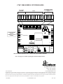
1
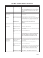
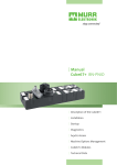
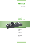
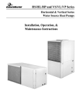
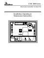
CMC 2000 Series
Electronic Controller Version 9.0
TEST
SHI
GND
24V
NN+
USD
CSD
ESD
GND
LOW
MED
HI
C
L
X
G
Y1
W1
R
Installation, Operating &
Maintenance Instructions
C2
LTS
P2
HPS
LPS
P3
P4
C3
C4
24 VAC
ON
1 2 3 4 5 6 7 8
WV
CLIMATEMASTER
COND
FAULT
LED's
RV
STG2
FAN HIGH RELAY
MED
FAN
LO
FAN
S/N
WV
RELAY
L1
L2
**
LO
COMP. RELAY
R.V.
RELAY
MED
Page 1
TABLE OF CONTENTS
Page
Page 2
Introduction
3
General Information
4
Overview
4
General Operating Parameters
4
Relay Ratings
4
Optional Components
4
Revision Identification
4
Features
4
Installation of Power Wiring
4
Single Phase Equipment
5
Three Phase Equipment and Single Phase over 10 AMPS
5
Unit Operation
5
Powering Up Unit
5
Normal Operation
5
Thermostat Inputs
5
R-HI-ME-LO Fan Speed Select
6
Dip Switch Settings
6
Energy Management Operation Modes
6
Safety Features
6
Fault Indications and Diagnostic LEDs
6
Maintenance
7
Test Mode
7
Interfacing the CMC 2000 Controller
7
Interfacing the CMC 2000 Series Controller to External Equipment
8
Replacing a Controller Board
8
Parts List
8
Trouble Shooting Chart: CMC 2000 Controllers
9
Control Board Trouble Shooting
11
Control Board Diagnostic Chart
11
CMC 2000 Series Controller Board Layout
12
INTRODUCTION
This Installation and Operation manual is for
ClimateMaster CMC 2000 Series Electronic Controller
(CMC).
ClimateMaster CMC Controllers are typically factory
installed within the control section of the ClimateMaster
HVAC equipment and are shipped with the unit. Sensors
and other peripherals are typically shipped loose in the
same carton for field installation.
Features
Electro-Mechanical
ClimateMaster offers three standard electronic controller
configurations of the CMC Controller to allow flexible
matching of controller features to application requirements. Refer to the table below to determine the features
available in the CMC Controller to be installed.
High Pressure Protection
S
Electronic
CMC-2001
S
Electronic
CMC-2005
S
Electronic
CMC-2010
S
Low Pressure Protection
S
S
S
S
Low Refrigerant Gas Protection
S
S
S
S
Low Water Flow Protection
S
S
S
S
Room Temperature Set Point - In Room
S
S
S
S
S
S
S
Room Temperature Set Point - Remote
Display Room Temperature - In Room
S*
S
Display Room Temperature - Remote
S*
Demand Load Shed
O
S
S
S
Low Voltage Protection
O
S
S
S
High Voltage Protection
O
S
S
S
Emergency Shutdown
O
S
S
S
Random Start
O
S
S
S
Anti-Short-Cycle Time-Delay
O
S
S
S
Condensate Overflow Switch
O
S
S
S
Intelligent Re-Set
O
S
S
S
Quick Service Test
S
S
S
Reduced Reversing Valve Operation
S
S
S
S
LED Status Lights
O
S
S
Night Setback
O
S
S
S
Night Setback Override - Remote
Night Setback Override - Local
S*
O
S
High/Low Fan Speed
Pump Restart
O
O
S
S
S
O*
S
O
Compressor Run Hours
S*
Compressor Starts
S*
Fan Run Hours
S*
Remote Alarm
S*
Local Alarm
O
O
O
O
Local Alarm For Condensate Overflow
O
O
O
S*
U
U
Remote Alarm For Condensate Overflow
O*
RS-485 Communication
S
Outdoor-Air Damper-Control
O
E
E
E
Motorized Water Valve
O
E
E
E
Totally-Automated Building Interface
O*
Leaving Water Temperature Display
O*
Multiple Units On One Thermostat
3
3
3
Leaving Air Temperature Display
S = Standard Feature
O*
O = Optional Feature
U = Upgrade
E = either Outdoor-Air Damper-Control or Motorized Water Valve can be selected, but not both.
*This feature requires a personal computer to link to the system with the required compatible software.
Page 3
GENERAL INFORMATION
Overview
This manual includes discussion on the following
controller options:
Centralized communications via Direct Digital Control
(DDC); Diagnostics; Fan speed control; Energy management functions; Controller use with electronic programmable thermostats; Controller use with damper or water
valve electric operators.
General Operating Parameters
Controllers with a serial number which begins with the
letter "E" and has part number 69626500 stamped above
the serial number is an "E" Revision Board. Please
consult the IOM literature, part number 69626510, for
details.
Features
The CMC 2000 Series controller offers the following
features which improve the operation and safety of water
source heat pump systems:
The following are general operating parameters for the
CMC 2000 Series Controller:
• Anti-short cycle protection
Operating Environment: 40° F (4.4° C) to 140° F
(60° C) 5 to 95% relative humidity, non-condensing.
• High and low voltage cutouts
Storage Environment: 0° F (-18° C) to 158° F (70° C)
5 to 95% relative humidity, non-condensing.
• Random start
Power Requirements: A dedicated 24 VAC, 50-60 Hz,
1 PH, 40 VA transformer is required.
• High and low pressure cutouts
• Low water temperature (freeze) protection
• Quiet reduced cycling reversing valve operation
• Diagnostic LED’s
• Reset lockout at unit or at disconnect
Relay Ratings
The following relays are included with the CMC 2000
Series Controller, part number 69626512:
• Compressor Relay; 2 HP at 277 VAC
• Intelligent reset
• Condensate overflow sensor
• Ability to work with any heat/cool electronic or electromechanical thermostat.
• Fan High Speed Relay; 2 HP at 277 VAC
• Night set back, compressor shut down and emergency
shut down.
• Reversing Valve Relay; 5 Amps at 24 VAC
• Elimination of time delays for field servicing
• Water Valve Relays: 5 Amps at 24 VAC
• RS-485 communications (Optional)
• Three-speed fan control (Optional)
Optional Components
The following optional components are available on the
CMC 2000 Series Controller, part number 69626513:
• Fan Medium, Low Speed Relay: 3/4 HP at 277 VAC
• Damper control relay (Optional)
• Electronic room sensor (Optional)
Installation of Power Wiring
! WARNING
▲
Optional RS-485 Communications
See CMC Series, Electronic Controller Version 8.9
Communications Option Installation, Operating and
Maintenance Manual, part number 69626514, for details.
Revision Identification
A Version 8.9 controller is identified by a serial number
greater than 30,000 and the part number 69626512 (or
part number 69626513) stamped above the serial number.
Controllers with a serial number less than 10,000 and
part number 69183000 stamped above the serial number
is a "D" Revision Board. Consult factory for details.
Page 4
All wiring must comply with the National Electric
Code and all local codes.
CAUTION: The CMC 2000 Series Controller uses
static sensitive CMOS components which may be
damaged by static. To prevent damage to the
components during service, DO NOT TOUCH
CIRCUIT BOARD COMPONENTS. HOLD THE
CIRCUIT BOARD BY THE EDGES ONLY.
Single-Phase Equipment
Wire Single-Phase equipment requiring less than 10
amps at 240 VAC (2.4 kva) as follows:
1.
2.
3.
Connect the incoming main power from an NEC or
local code approved disconnect device to terminals
L1 and L2 on the control board. Refer to the wiring
diagram attached to the unit.
Connect a ground wire from the power source.
Earth-ground couple to the chassis ground screw is
provided in the control box. Use copper conductors
only.
Do not run the AC power wiring in the same conduct
with low voltage wiring.
Three-Phase Equipment and Single-Phase
over 10 AMPS:
Wire Three-Phase equipment and Single-Phase equipment requiring 10 amps or more at 240 VAC (2.4 kva) as
follows:
1. Connect the incoming main power from an NEC
approved disconnect device to the line voltage
connections in the control box. Refer to the wiring
diagram attached to the unit.
2. Connect a ground wire from the power source. Earthground couple to the chassis ground screw is
provided in the control box. Use copper conductors
only.
3. Do not run the AC power wiring in the same conduct
with low voltage wiring.
UNIT OPERATION
Powering up Unit
Turn on power. Verify that the green LED light is
illuminated. The following conditions indicate that a fault
may be present.
• Green LED is not illuminated (located below dip switch
- Version E)
• Four (4) alarm LED's are blinking
• One (1) alarm LED is illuminated
Refer to diagnostic and Control Board Trouble Shooting
charts on pages ?-?.
Normal Operation
The Controller operates in normal mode when the green
LED is illuminated to indicate power is applied and no
alarm LED’s are illuminated or blinking.
Thermostat Inputs
R - G Fan Only - The fan energizes when a closure
occurs. On units without fan speed control, the closure is
controlled by the tap at the motor wired to meet the
installation requirements. On units where the fan speed
option has been supplied, closure occurs at the speed
selected.
R - Y Cooling - The first time a closure occurs, the fan
starts immediately unless one of the Hi, Me, Lo inputs
are activated, due to the fan switch on the thermostat.
The water valve relay is then energized, which is
followed by a 5 to 80 second random start delay. At this
time, a 20 second fixed delay is applied, after which the
reversing valve is energized. One second later, the
compressor is energized.
When the input opens, the compressor is de-energized.
One second later the water valve is de-energized. After
an additional 30 seconds, the fan is de-energized unless
one of the Hi, Me, Lo inputs are activated.
On all subsequent closures, the sequence is the same as
for the initial closure except that the 5 to 80 second
random start delay is omitted, and the reversing valve
remains in the cooling mode until the first demand for
heating.
NOTE: The compressor energizes 20 seconds after the
water valve and the fan are energized unless the
controller has damper option selected. (See dip switch
#6) If the damper option is selected, the water valve
relay is energized 30 minutes after the compressor
first start-up at initial power on or the deactivation of
the USD setback function.
R - W Heating - R-Y Heating operations follow the same
sequence of functions as R-Y Cooling except that the
reversing valve is de-energized during the heating mode
and remains de-energized until the first demand for
cooling.
R - L Night Setback (Unoccupied) Override - A
momentary closure between R and L returns the unit to
the occupied mode for 2 hours. At the end of this 2 hour
period, the unit returns to the unoccupied mode. If the
closure between R and L is continuous, the controller
Page 5
acts as if a thermostat is connected and returns the unit to
continuous heat until the thermostat is satisfied.
NOTE: To reset the board at the thermostat, the fan
switch on the thermostat must be in the "AUTO"
position.
R-HI-ME-LO Fan Speed Select (Optional)
CAUTION: After changing dip switch settings, turn
the unit off at the disconnect and power up to initiate
the new unit settings.
Fan Speed Control (Optional) - Fan speed is manually
selected at the thermostat for high medium or low The
selected speed provides contact closure between R-Hi or
R-Me or R-Lo to activate the fan. Consult equipment
blower performance tables in the product specifications
for air volume and pressure characteristics typical of each
speed. Select the speed which allows the blower to
overcome any excess static pressure drop from ductwork,
registers or grilles connected to unit supply or return
opening.
Dip Switch Settings
Dip Switch #1-2 - Only used when an ET Series Thermostat is connected to the CMC Controller. Use dip switches
to set addresses for multi-stage or multiple CMC boards
connected to one ET Series Thermostat. For master/slave
applications, (maximum of three CMC boards connected
to one ET Thermostat), each CMC board shall have
identical addresses. For two stage heat pump, which have
two CMC boards, or for multi-stage control, address first
CMC board by placing dip switch #1 "OFF", dip switch
#2 "ON". Address second CMC board by placing dip
switch #1 "ON" and dip switch #2 "OFF". For a third
controller, set both dip switches "OFF".
Dip Switch #3 - For DDC option only. "ON" - When ET
Series Thermostat is connected to the CMC board.
"OFF" - When a space sensor is connected to the
CMC board.
Dip Switch #4 - "ON" - ˚F. "OFF"- C. For DDC option
only (Version 8.9 or higher one.)
Dip Switch #5 - "ON" - Fan shall stop when heat pump is
in a fault mode. "OFF" - Fan continues to operate in a
fault mode.
Dip Switch #6 - "ON" - Auxiliary relay for pump restart
or motorized valve option is energized 20 seconds
prior to compressor energization. "OFF" - Auxiliary
relay for damper option opens 30 minutes after USD
returns to occupied mode.
Dip Switch #7- "ON" - Safety contacts LTS, LPS and
HPS are normally open. "OFF" - Safety contacts
LTS, LTS and HPS are normally closed.
Dip Switch #8- "ON" - Resets board from main power
switch on a console unit. A horizontal or vertical unit,
reset is accomplished by momentarily turning the
system switch to the "OFF" position at the thermostat. "OFF" Reset function by cycling the main power
only.
Page 6
Energy Management Operation Modes
Load Shedding - (CSD Terminal)
When the CSD terminal is connected to a chassis ground
through an external contact closure, the compressor is
stopped. When the contact opens, the compressor returns
to control by the thermostat after random time delay and
anti-short-cycle times functions have elapsed. This
function cannot be overridden.
Unoccupied - Night Setback- (USD Terminal)
When the USD terminal is connected to a chassis ground
through an external relay closure, the compressor and the
fan de-energize. When the USD terminal is opened, the
unit returns to occupied mode after all random start and
anti-short-cycle time functions have elapsed. This
function can be overridden at the thermostat.
Emergency Shutdown - (ESD Terminal)
When the ESD terminal is connected to a chassis ground
through an external contact closure, the controller deenergizes all outputs. These outputs remain de-energized
until the ESD terminal is opened. The unit returns to
normal operation after random start and anti-short-cycle
times functions have elapsed. This function cannot be
overridden.
Safety Features
The following safety features are provided to protect the
compressor, heat exchanger, wiring and other components
from damage caused by operation out of the range of
design conditions .
HPS - High Pressure Switch (NC) - Green
LED
This switch opens at a refrigerant pressure of 375 PSI.
The high pressure LED is lit.
NOTE: Some units may be equipped with Normally
Open (N.O.) switches.
LPS - Low Pressure Switch (NC) - Orange
LED
This switch opens at pressure drops below specification.
This input will be ignored for the first two minutes after a
demand for heating or cooling. The low Pressure LED is
lit.
NOTE: Some units may be equipped with Normally
Open (N.O.) switches.
Fault Indication and Diagnostic LEDs
The "X" terminal on the thermostat connector turns on
when any fault occurs. This illuminates an LED on the
thermostat subbase. A 24-volt DC relay can be connected
between X and C to provide a "dry contact" fault signal.
(85 mA is maximum coil load.)
Maintenance
LTS - Low Temperature Switch (NC) - Red
LED
Check the condensate sensor for operation twice a year.
Clean the sensor of any dirt that may have accumulated.
This switch opens when the temperature of the water
entering the condenser bundle drops below the set point.
The low temperature (freeze) LED is lit.
Test Mode
NOTE: Some units may be equipped with Normally
Open (N.O.) switches.
HCLS - Condensate Overflow Sensor -Yellow
LED
Closure of this input activates the lockout circuit. This
input operates when the water level in the condensate pan
rises to the height of the sensor. The condensate overflow
LED is lit.
Under and Over Voltage Protection
When an under or over voltage condition exists the
controller locks out the unit. When the condition clears
the controller releases the unit to normal operation and
the compressor runs after random start and anti-shortcycle timers are met. All alarm LED's flash.
Faulty Wiring
If the thermostat is wired incorrectly or when there is a
simultaneous call for heating and cooling, the 2 inner
alarm LED's are lit (Green and Orange).
Reset of Lockout
The controller is reset at the thermostat or at the disconnect switch, (See Dip Switch #8, settings.)
Intelligent Reset
The controller has an intelligent reset feature. After a
safety control activates, the controller locks out the unit
for 10 minutes. At the end of this period, the controller
checks to verify that all faults have cleared. If faults have
cleared, the controller restarts the unit. Should any fault
occur within the subsequent 30 minutes, the controller
locks out the unit until the unit is manually reset.
Test mode allows the serviceman to check the operation of
the controller quickly. A jumper across the test terminals
on the circuit board activates test mode. All time delays
are eliminated. It is important to remove the jumper upon
completion of service.
NOTE: In the test mode, the USD override (a
momentary closure between R and L) will not
function.
Interfacing the CMC 2000 Controller
The CMC 2000 has a 10 pin terminal block for thermostat
and the optional fan speed selector as shown in Table 1.
The CMC 2000 has an additional five pin terminal block
for the "ET" Series Electronic Thermostat.
Table 1- Ten Pin Reference Table
Term
R
W1
Y1
G
L
X
C
HI
ME
LO
Description
R on thermostat
W1 on thermostat
Y1 on thermostat
G on thermostat
L on thermostat
Fault output
Board 24 common
HI on fan speed selector
ME on fan speed selector
LO on fan speed selector
For ET Thermostat Only
SHI Shield wire
GND 24 V common
24 V 24 VAC
N- Communication
N+ Communication
Function
24 VAC 1/2 wave rectified
Heat mode
Cool mode
Fan only mode
Override unit shutdown input
24 VDC "X" terminal on thermostat
24 V (Common)
High fan speed (Optional)
Medium fan speed (Optional)
Low fan speed (Optional)
Shields communication
24 V common
24 VAC 1/2 wave rectified
RS-485 transmit
RS-485 recieve
Page 7
Interfacing the CMC 2000 Series Controller
to External Equipment
Contact Factory for instructions to wire DDC controllers
by others to the CMC board. The controller may be
interfaced to any electro-mechanical thermostat which has
"R" to "Y", and "R" to "W" terminals.
DO NOT USE A HEAT PUMP THERMOSTAT.
Thermostat Interface: Electronic thermostats which
operate using both 24 VAC power and 24 V common can
be interfaced to the thermostat terminals. If the thermostat
requires a dedicated transformer, connect the thermostat
transformer return line to ground on the board. Up to
three units can be controlled in parallel from one
thermostat without the use of adaptors or special wiring.
Feature Activation: Unit shutdown (USD), compressor
shutdown (CSD) and emergency shutdown (ESD) can be
connected in parallel with other controller boards.
Grounding any of these terminals activates the selected
feature. Opening the circuit returns the unit to normal
operation.
Test Mode: To use test mode, connect a jumper with two
1/4" quick connects to the terminals marked test. Remove
the jumpers after completion of service.
NOTE: Failure to remove jumpers may reduce
PARTS LIST CMC VERSION 8.9 CONTROLLER ≠
Component Description
Part Number
CMC-2001
Basic Controller
69626512
Controller with Three Speed Fan Relays
69626513
RS-485 Adapter Board
69626511
Dry Contact for Alarm Auxiliary Relay
68537942
Transformers:
115/24
68538022
208/24
68528028
230/24
68538028
277/24
68538029
380/24
68538043
460/24
68538030
575/24
68538016
Discharge Air Sensor
69626502
Leaving Water Sensor
69626502
Condensate Water Kit
69180118
Wall Sensor Assembly††
69626503
Wall Sensor Cover Only
69605000
Wall Sensor with Override Assembly
69626504
Cover with Override
69605000**
** Customer must drill hole for overrides.
†† ET Series Thermostat may be used as a wall sensor.
≠ For earlier versions of the CMC 2000 Series Controller,
see IOM for CMC Controller Revision E, Part number
69626510.
equipment life and invalidates product warranties.
Ambient Temperature Sensor: A five pin terminal block is
used for ClimateMaster Electronic thermostats and for the
optional ambient temperature sensor.
Water Valve or Damper Relay contacts: These are dry
contacts which can be connected to any external valve or
damper up to 5 amps (24 VAC). For damper function, set
dip switch #6 to "OFF". For water valve function, set dip
Switch #6 to "ON".
Fault Signal for DDC Systems by other Manufacturers:
A "fault" signal required by another manufacturer's DDC
system is provided by means of a dry contact closure
through the use of a field or factory installed, 24 VDC
pilot relay.
Replacing a Controller Board
Follow the steps below to replace a controller board:
1. Disconnect main power to the unit.
2. Label all wires or refer to the wiring diagram. Disconnect all wires from the controller.
3. Remove the controller from the control box. Use long
nose pliers to "squeeze" the plastic stand offs and pull
the controller board out of the box.
4. Align the six holes on the controller board above the
six stand offs and push the replacement controller
board into place.
5. Connect all wires according to the wiring diagram or
according to the wire labels.
6. Apply power to the unit.
7. Test the unit to assure proper operation.
Trouble shooting chart CMC 2000 Controllers
Start
Did unit
attempt to
start?
No
Did unit
lockout at
start-up?
Check which LED
on control board
illuminates.
Yes
No
See Yes
page 10
Unit short
cycles?
No
See Yes Only fan runs?
page 10
LTS
LPS
See
page 9
See
page 9
HPS
See
page 9
No
See Yes
page 10
Only
compressor
runs?
See
LTS
page 10 &HPS
No
Did unit
lockout during
some period
of operation?
None illuminate.
Replace CMC
board and retest.
No
See No
page 11
Does unit
operate on
cooling?
Yes
Unit is OK.
Page 8
Check main power
and follow
instructions (page 9).
No
Yes
COND.
See
page 10
CONTROL BOARD TROUBLE SHOOTING
Power Problems
Indicator
Green LED Off
4 Alarm LED's blinking
LTS Low Temperature
Switch Lock-Out
Possible Cause
Reduced or no water flow
Solution
Check line voltage circuit breaker and disconnect. Check for 24
VAC between C1 and P1.
Check 24 VAC between C1 and P1. If there is no voltage, check
for primary power supply to transformer. If power supply is on,
replace transformer. If voltage is less than 19 VAC or more than
27 VAC, check main power supply for over or under voltage
conditions.
Solution
Check pump operation and/or valve settings; adjust to proper flow
rate per design.
Water temperature out of range Bring water temperature in loop to design conditions.
Bad Low Temperature Switch
Disconnect, then reconnect main power to reset any tripped safety
switches. If unit does not run, jumper the LTS terminals on the
control board. If unit runs while jumper is attached, replace the
LTS switch. If unit still does not run, replace board.
Wrong Dip Switch #7
Setting Set dip switch for correct safety NO or NC.
(See page 7.)
LPS Low Pressure
Switch Lock-Out
Loss of refrigerant charge
Check system pressures.
Orange LED ON
Water temperature too low
Increase water temperature in loop.
Low Water Flow (Heating
Mode)
Check pump operation and/or valve setting; adjust to proper flow
rate per design.
Inadequate air flow (Cooling
Mode)
Check air filter and duct work.
Bad Low Pressure Switch
Disconnect, then reconnect main power to reset any tripped safety
switches. If unit does not run, jumper the LPS terminals on the
control board. If the unit runs, while the jumper is attached,
replace the LPS switch. If the unit still does not run, replace
board.
Wrong Dip Switch #7 Setting
Set dip switch for correct safety NO or NC. (See page 7.)
HPS High Pressure
Switch Lock-Out
Reduced or no water flow
(Cooling Mode)
Check pump operation and/or valve setting; adjust to proper flow
rate per design.
Green LED ON
Water temperature out of Range Bring water temperature in loop to design conditions.
Red LED ON
Inadequate air flow (Heating
Mode)
Check air filter and ductwork.
Bad High Pressure Switch
Disconnect, then reconnect main power to reset any tripped safety
switches. If unit does not run, jumper the HPS terminals on the
control board. If the unit runs, while the jumper is attached,
replace the HPS switch. If the unit still does not run, replace
board.
Wrong Dip Switch #7 Setting
Set dip switch for correct safety NO or NC. (See page 6.)
Page 9
CONTROL BOARD TROUBLESHOOTING (CON'T)
Condensate OverFlow Switch
Yellow LED ON
Unit Short Cycles
Only Fan runs
Possible Cause
Blocked drain
Solution
Check for blockage and clean drain-pan
Improper "P" trap
Check trap, rework if required
Overflow sensor shorted
Check for short and dirt on sensor pins
Sensor location
Move sensor to new location
Control Board
If unit still locks-out on condensate, disconnect one wire from
condensate terminal, If unit still locks-out, replace control board
Test terminals jumpered
Check test mode terminals. Remove any jumper wire.
Dirty filter
Check and clean air filter
Water flow
High water flow and high temperature can short cycle the unit in
heating. Assure that water flow and temperature are within design
conditions
Unit selection
Unit may be oversized for the space. Check size versus design
calculations
Compressor overload
Check and replace if necessary
Thermostat position*
Ensure that thermostat is in "ON" mode. Adjust thermostat to a
demand position.
Wiring
Check "Y" and "W" terminal wiring. Jumper between "R" and "Y"
or between "R" and "W". If compressor starts, check wiring and
thermostat. If compressor does not start, replace board.
*If test terminals are not jumpered, wait for the 5 minute anti-short
cycle time delay.
Only Compressor runs
Fan Motor Relay
Connect jumper between "R" and "G" on thermostat connector.
Check voltage on both load and line side of the fan motor relay on
the control board. If no voltage on load side but voltage on line
side, replace control board.
Fan Motor
If fan relay is used as a pilot relay to drive the fan contactor, check
to see that the fan relay is closed. Check voltage across the fan
contactor.
If voltage is present but the contactor is not closed, change
contactor.
If contactor is closed but fan does not run, check for line voltage on
load side of contactor.
If line voltage is present, check wiring to fan motor.
If wiring is correct, change the fan motor.
If voltage is acceptable on motor terminals and fan capacitor is
functioning, replace the fan motor.
Page 10
CONTROL BOARD TROUBLESHOOTING (CON'T)
Does not operate on
cooling
Possible Cause
Reversing Valve
Solution
Set thermostat on demand for cooling. Check for 24 VAC on
the Reversing Valve terminals on the control board. If 24
VAC is missing and the unit runs in heating, replace the
control board.
Defective Reversing Valve If there is 24 VAC to the Reversing Valve solenoid, replace
the solenoid.
Reversing Valve stuck
Replace the Reversing Valve.
LTS and HPS LEDs On
"R" to "Y" and "R" to "W" Disconnect the thermostat. Jump "R" to "G" and "R" to "Y".
are closed at the same time. If unit runs in cooling, remove "R" to "Y" jumper and jump
"R" to "W". If unit runs in heating, correct problems in the
thermostat or the wiring.
HPS, LTS, COND
All flash
Low pressure OK
Defective microchip
Replace plug-in chip
All LEDs On constant
Defective microchip
Replace plug-in chip
(If blinking, see Power
Problems.)
CONTROL BOARD DIAGNOSTICS CHART
CMC 2000 Terminals Version 9.0
Between L1 & L2
Voltage
Line voltage application only, 208/230/277 single phase units
under 2 1/2 tons. Pilot-duty application, 24 VAC for all 3 phase
units and single phase units 2 1/2 tons and above.
RV (Two Terminals)
24 VAC
WV (Two Terminals)
Dry Contacts (Rated).
5A @ 24 VAC
Between C1 & P1
24 VAC
Between C2 & P2
24 VAC
Between C3 & P3
24 VAC
Between C4 & P4
24 VAC
Between R & C
24 VAC, 1/2 wave rectified
Between X & C
24 VDC during fault condition only.
Between L1 & Compressor
Application Specific. See drawings.
Between L1 & FAN
Application Specific. See drawings.
STG2
Do not ground. In dual compressor units, STG2 shares condensate alarm between two CMC boards.
Page 11
CMC 2000 SERIES CONTROLLERS
SHUTDOWN
OPTIONS
"ET" SERIES T'STAT
OR REMOTE SENSOR
ONLY
TEST
SHI
GND
24V
NN+
USD
CSD
ESD
GND
LOW
MED
HI
C
L
X
G
Y1
W1
R
USD
CSD
ESD
GND
LO
MED
HI
C
L
X
G
Y1
W1
R
SHI
GND
24V
NN+
T'STAT
C2
LTS
PLUG-IN SOCKET
FOR DDC
COMMUNICATIONS
BOARD
P2
HPS
LPS
P3
P4
C3
C4
24 VAC
ON
1 2 3 4 5 6 7 8
WV
CLIMATEMASTER
COND
FAULT
LED's
RV
STG2
FAN HIGH RELAY
MED
FAN
LO
FAN
S/N
**
LO
R.V.
RELAY
WV
RELAY
L1
L2
COMP. RELAY
MED
*Medium and low speed fan relays available only on part number 69626513
Note: See page 6 for details regarding the main board dip switches.
7300 S.W. 44th Street
Oklahoma City, OK 73179
Phone: 405-745-6000
Fax: 405-745-6058
www.climatemaster.com
Part #:69626515
ClimateMaster works continually to improve its products. As a result, the design and specifications of each product at the time for order may be changed
without notice and may not be as described herein. Please contact ClimateMaster’s Customer Service Department at 1-405-745-6000 for specific
information on the current design and specifications. Statements and other information contained herein are not express warranties and do not form the
basis of any bargain between the parties, but are merely ClimateMaster’s opinion or commendation of its products.
1-08-IM100
Page
12
© ClimateMaster 1994
Rev.1/98