1
Tranquility® Digital Air Handler (TAH)
Air Handler for
®
Tranquility
Tranq
Split Series
Installation, Operation &
Instal
Mainte
Maintenance Instructions
97B0101N01
Rev: 11/19/12
Table of Contents
Model Nomenclature
3
Blower Data
17
General Information
4
Electrical - Power Wiring
18
Pre-Installation
4
Electric Heat Installation
19
Safety
5
Electric Heat Wiring
20-21
Physical Data
6
Electric Heat Staging Options
21
Dimensional Data
7
Wire Diagram
22
Installation
8-13
Unit & System Checkout
23
Installation - AXM Control
14
Maintenance
23
Electrical - Thermostat Wiring
15
Warranty
24
ECM Blower Control
16
Revision History
26
Tranquility Air Handler (TAH)
R e v. : N o v. 1 9 , 2 0 1 2
This page was intentionally left blank.
2
Geothermal Heat Pump Systems
Tranquility Air Handler (TAH)
R e v. : N o v. 1 9 , 2 0 1 2
Model Nomenclature
1
2 3
4 5 6
7
8
9
10
11
12
T AH 0 2 6 B G S M A S
MODEL TYPE
FUTURE USE
T = TRANQUILITY HFC-410A
S = STANDARD
CONFIGURATION
CABINET SIZE
AH = AIR HANDLER
(WIDTH, INCHES)
A SIZE 026 ONLY; 18.5 WIDTH
B SIZES 026, 038, 049 ONLY; 22.5 WIDTH
NOMINAL CAPACITY
C SIZES 038, 049, 064 ; 25.5 WIDTH
026
038
049
064
REVISION
CABINET OPTIONS
B = CURRENT REVISION
WITH AXM CONTROL
M = MULTI-POSITION
VOLTAGE
CONTROLS
G = 208-230/60/1
S = STANDARD
( NOTE; FIELD CONVERTIBLE TO 115v )
3
Tranquility Air Handler (TAH)
R e v. : N o v. 1 9 , 2 0 1 2
General Information
Air Handler Description
ClimateMaster Tranquility® Digital Air Handlers are designed
for use with ClimateMaster indoor/outdoor split units and are
available for vertical upflow or downflow, and horizontal left
or horizontal right airflow.
• New AXM board allows 4-wire connection with
communicating split (TEP/TES) and communicating
thermostat (ATC). Airflow and accessories can be
configured on the thermostat in plain English.
• Air coils are constructed of aluminum fins bonded to
internally grooved copper tubing.
• Air coils are tested at the factory with an extensive
refrigerant leak check.
• Air coils have sweat refrigerant connections.
• Ideally suited for new installations or add on air
conditioning.
• Feature two sets of 3/4” [14.1 mm] F.P.T. Condensate
drain connections for ease of connection.
• Air Handlers are A.H.R.I. certified for system application
with ClimateMaster indoor and outdoor split units.
• Condensate drain pan is constructed of high grade, heat
resistant, corrosion free thermal-set material.
• Bi-Directional airflow eliminates the need to switch any
internal components from horizontal left to right.
• Unique drain pan design maximizes application flexibility
and condensate removal.
Examine all pipes, fittings, and valves before installing any of
the system components. Remove any dirt or debris found in
or on these components.
Inspection
Upon receipt of the equipment, carefully check the shipment
against the bill of lading. Make sure all units have been
received. Inspect the packaging of each unit, and inspect each
unit for damage. Insure that the carrier makes proper notation
of any shortages or damage on all copies of the freight bill and
completes a common carrier inspection report. Concealed
damage not discovered during unloading must be reported
to the carrier within 15 days of receipt of shipment. If not filed
within 15 days, the freight company can deny the claim without
recourse. Note: It is the responsibility of the purchaser to file
all necessary claims with the carrier. Notify your equipment
supplier of all damage within fifteen (15) days of shipment.
WARNING!
WARNING! These instructions are intended as an aid to
qualified licensed service personnel for proper installation,
adjustment and operation of this unit. Read these
instructions thoroughly before attempting installation
or operation. Failure to follow these instructions may
result in improper installation, adjustment, service or
maintenance possibly resulting in property damage,
personal injury or death.
Storage
Equipment should be stored in its original packaging in a
clean, dry area. Store units in an upright position at all times.
Stack units a maximum of 3 units high.
CAUTION! DO NOT store or install units in corrosive
environments or in locations subject to temperature
or humidity extremes. Corrosive conditions and high
temperature or humidity can significantly reduce
performance, reliability, and service life.
Unit Protection
Cover units on the job site with either the original packaging
or an equivalent protective covering. Cap the open ends of
pipes stored on the job site. In areas where painting, plastering,
and/or spraying has not been completed, all due precautions
must be taken to avoid physical damage to the units and
contamination by foreign material. Physical damage and
contamination may prevent proper start-up and may result in
costly equipment clean-up.
4
Pre-Installation
Installation, Operation, and Maintenance instructions
are provided with each unit. Horizontal equipment is
designed for installation above false ceiling or in a ceiling
plenum. Other unit configurations are typically installed
in a mechanical room. The installation site chosen should
include adequate service clearance around the unit. Before
unit start-up, read all manuals and become familiar with the
unit and its operation. Thoroughly check the system before
operation.
Prepare units for installation as follows:
1. Compare the electrical data on the unit nameplate with
ordering and shipping information to verify that the
correct unit has been shipped.
2. Keep the cabinet covered with the original packaging
until installation is complete and all plastering, painting,
etc. is finished.
3. Verify refrigerant tubing is free of kinks or dents and that
it does not touch other unit components.
4. Inspect all electrical connections. Connections must be
clean and tight at the terminals.
CAUTION!
CAUTION!
CAUTION! CUT HAZARD - Failure to follow this caution
may result in personal injury. Sheet metal parts may have
sharp edges or burrs. Use care and wear appropriate
protective clothing, safety glasses and gloves when
handling parts and servicing.
Geothermal Heat Pump Systems
Tranquility Air Handler (TAH)
R e v. : N o v. 1 9 , 2 0 1 2
Safety
The installation of water source heat pump units and all
associated components, parts and accessories which make
up the installation shall be in accordance with the regulations
of ALL authorities having jurisdiction and MUST conform to
all applicable codes. It is the responsibility of the installing
contractor to determine and comply with ALL applicable
codes and regulations.
Replacement Parts
Any replacement part must be the same as or an approved
alternate to the original part supplied. The manufacturer will
not be responsible for replacement parts not designed to
physically fit or operate within the design parameters the
original parts were selected for. When ordering replacement
parts, it is necessary to order by part number and include
the complete model number and serial number from the coil
rating plate. (See parts list for unit component part numbers.
Parts are available through the local distributor.)
Safety
Warnings, cautions and notices appear throughout this
manual. Read these items carefully before attempting any
installation, service, or troubleshooting of the equipment.
DANGER: Indicates an immediate hazardous situation, which
if not avoided will result in death or serious injury. DANGER
labels on unit access panels must be observed.
CAUTION!
CAUTION! It is recommended that an auxiliary
secondary drain pan be installed under units containing
evaporator coils that are located in any area of a structure
where damage to the building or building contents may
occur as a result of an overflow of the coil drain pan or a
stoppage in the primary condensate drain piping.
WARNING!
WARNING! All refrigerant discharged from this unit must
be recovered WITHOUT EXCEPTION. Technicians must
follow industry accepted guidelines and all local, state, and
federal statutes for the recovery and disposal of refrigerants.
To avoid leakage of compressor oil, refrigerant lines of the
compressor must be sealed after it is removed.
CAUTION!
CAUTION! To avoid equipment damage, DO NOT use
these units as a source of heating or cooling during the
construction process. The mechanical components and
filters will quickly become clogged with construction dirt
and debris, which may cause system damage.
WARNING: Indicates a potentially hazardous situation, which
if not avoided could result in death or serious injury.
CAUTION: Indicates a potentially hazardous situation or an
unsafe practice, which if not avoided could result in minor or
moderate injury or product or property damage.
NOTICE: Notification of installation, operation or maintenance
information, which is important, but which is not hazardrelated.
WARNING!
WARNING! The EarthPure® Application and Service
Manual should be read and understood before
attempting to service refrigerant circuits with HFC-410A.
WARNING!
WARNING! To avoid the release of refrigerant into the
atmosphere, the refrigerant circuit of this unit must be
serviced only by technicians who meet local, state, and
federal proficiency requirements.
5
Tranquility Air Handler (TAH)
R e v. : N o v. 1 9 , 2 0 1 2
Unit Physical Data
Model
026-A
026-B
038-B
038-C
049-B
049-C
064-C
Emerson ECM Fan Motor & Blower in. [cm]
Liquid I.D.
3/8 [0.95]
3/8 [0.95]
3/8 [0.95]
3/8 [0.95]
3/8 [0.95]
3/8 [0.95]
3/8 [0.95]
Suction I.D.
3/4 [1.9]
3/4 [1.9]
7/8 [2.22]
7/8 [2.22]
7/8 [2.22]
7/8 [2.22]
7/8 [2.22]
Fan Motor Type/Speeds
ECM Variable
Fan Motor (hp)
9 x 7 [229 x 178]
Air Coil Dimensions (H x W)
in. [mm]
3 - 2 Row 14 x 17 [356 x 432]
Filter Standard - 1” [25mm]
Throwaway
6
1/2
Blower Wheel Size (Dia x W)
in. [mm]
16 x 20 [406 x 508]
1
12 x 10 [305 x 254]
3 - 3 Row 24x17
[610 x 432]
3 - 2 Row 24 x 17 [610 x 432]
20 x 20 [508 x 508]
20 x 24
[508 x 610]
20 x 20
[508 x 508]
20 x 24 [508 x 610]
Weight - Operating lbs. [kg]
80 [36]
163 [74]
173 [78]
181 [82]
180 [82]
188 [85]
198 [90]
Weight - Packaged lbs. [kg]
96 [44]
179 [81]
198 [90]
206 [93]
218 [99]
226 [103]
236 [107]
Geothermal Heat Pump Systems
Tranquility Air Handler (TAH)
R e v. : N o v. 1 9 , 2 0 1 2
Unit Dimensional Data
Detail A
J
A = Primary Drain - Vertical,
Horizontal and Downflow
Configuration
8.5 [21.6]
6.7 [17.0]
5.6 [14.2]
E
B = Secondary Drain - Vertical
and Downflow Configuration
C
4.5 [11.4]
3.7 [9.4]
A
B
C = Secondary Drain - Horizontal
Configuration
0.0
H
D
G
0.0 1.6
[4.0]
F
3.6
[9.1]
5.8
[14.7]
Detail A
Scale 5/32
[0.4]
5.9
[15.0]
5.5
[14.0]
8.5
[21.6]
3.6
[9.4]
See Detail A
R.A. Opening
A
0.625
[1.6]
Overall Cabinet
Cabinet
Size
A
Width
R.A. Opening
C
0.75
[1.9]
0.625
[1.6]
1
2
3
4
5
6
B
Height
C
Depth
D
E
F
G
H
J
in.
18.5
44.0
22.0
14.0
14.0
2.3
2.3
4.1
4.1
cm.
47.0
111.8
55.9
35.6
35.5
5.8
5.8
10.3
10.3
in.
22.0
55.0
22.0
18.0
18.0
2.1
2.1
2.1
2.1
cm.
55.9
139.7
55.9
45.7
45.7
5.2
5.2
5.2
5.2
in.
25.5
59.0
22.0
18.0
18.0
3.8
3.8
2.1
2.1
cm.
64.8
149.9
55.9
45.7
45.7
9.9
9.9
5.2
5.2
0.875
[2.2]
A - Cabinet
B - Cabinet
C - Cabinet
7
Tranquility Air Handler (TAH)
R e v. : N o v. 1 9 , 2 0 1 2
Installation
The Tranquility Air Handlers are designed for upflow, horizontal, and downflow applications. The coils have a dry nitrogen
holding charge and are equipped with brazing stub refrigerant connections for easy installation. Both models come
equipped with a factory installed TXV.
The installer should read the installation manual supplied
with the compressor section for refrigerant line set sizing,
connection procedure, and other important information pertaining to the system installation.
The installer should:
1. Where precise forming of refrigerant lines is required, a
copper tubing bender is recommended for small diameter
tubing. One should avoid sharp bends and contact of the
refrigerant lines with metal surfaces.
2. Refrigerant lines should be protected where they pass
through the raw edges of holes.
3. Air Handler must be level for proper condensate drainage.
4. Seal the openings into the cabinet to reduce risk of condensate blow off from the coil.
Air Handler Installation
WARNING!
WARNING! Electric furnaces may be connected to
more than one supply circuit.
Charging the System
TAH Air Handlers are designed to match TEP/TES split
units. For correct charging, please refer to the Compressor
Section IOM.
Upflow Installation
1. Position unit on plenum box or other suitable foundation.
Provide a minimum height for proper unrestricted airflow
based on CFM requirement for each unit size.
2. If a return air duct is connected to the air handler, it must
be the same dimensions as shown in the outline drawing in
Figure 2.
3. Plenum box and unit should be isolated from the foundation
using a suitable isolating material.
4. Openings where field wiring enters the cabinet must be
completely sealed. Location of power entry is shown on the
outline drawing.
5. After ductwork connections are made, seal airtight and per
local codes.
Downflow Installation
1. Position unit on plenum box or other suitable foundation.
Provide a minimum height for proper unrestricted airflow
based on CFM requirement for each unit size.
2. If a return air duct is connected to the air handler, it must
be the same dimensions as shown in the outline drawing in
Figure 2.
3. Plenum box and unit should be isolated from the foundation
8
using a suitable isolating material.
4. Openings where field wiring enters the cabinet must be
completely sealed. Location of power entry is shown on the
outline drawing.
5. After ductwork connections are made, seal airtight and per
local codes.
6. The unit is then placed with the blower side down and the
coil is replaced on the coil channel supports with the drain
connections at the bottom. The unit is now in downflow
position with front access.
Position the ECM wire harness connection at the 4 to 8
o’clock position to prevent condensation from entering
motor controller.
7. If a return duct is connected to the air handler, it must be the
same dimensions as the return opening.
8. After ductwork connections are made, seal airtight and per
local codes.
Horizontal Right Installation
For maximum efficiency and customer ease of filter
maintenance, it is recommended that a properly sized
remote filter grille be installed for horizontal applications.
Airflow should not exceed the face velocity of the filter being
used. The factory installed filter should then be removed
from the unit.
1. To convert the unit to horizontal right, front access, slide the
coil out on the coil channel supports and rotate the complete
coil 180 degrees.
2. The coil is then inserted back into the cabinet on the
opposite side coil channel supports. The unit is now
horizontal right with front access.
Position the ECM wire harness connection at the 4 to 8
o’clock position to prevent condensation from entering
motor controller.
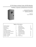
3. If the unit is suspended, it must be supported from the
bottom near both ends as well as the middle to prevent
sagging. The service access must remain unobstructed. If
the unit is supported along the length of the front and back
with rails, the air handler only needs to be suspended at
both ends. See Figure 1.
If the unit is not suspended it must be supported as
mentioned above and isolated carefully to prevent sound
transmission. Vibration isolators (purchased locally) must be
placed under the unit.
4. It is always recommended that an auxiliary drain pan be
installed under a horizontal air handler (See Condensate
Piping) to prevent possible damage to ceilings.
5. Isolate the auxiliary drain pan from the unit or from the
structure.
6. Connect the auxiliary drain line to a separate drain line
(no trap is needed in this line) and terminate according to
national and local codes.
7. If a return duct is connected to the air handler, it must be the
same dimensions as the return opening shown in the outline
drawing on Figure 2.
8. Openings where field wiring enters the cabinet must be
completely sealed.
9. After ductwork connections are made, seal airtight and per
local codes.
Geothermal Heat Pump Systems
Tranquility Air Handler (TAH)
R e v. : N o v. 1 9 , 2 0 1 2
Installation
Figure 1: Mounting Installation Options
Tranquility 27
Auxixiary
Drain Pan
EarthPure®
Rail
Tranquility 27
EarthPure®
Tranquility 27
Horizontal Left Installation
1. For maximum efficiency and customer ease of filter
maintenance, it is recommended that a properly sized
remote filter grille be installed for horizontal applications.
Airflow should not exceed the face velocity of the filter being
used. The factory installed filter should then be removed
from the unit.
2. Unit is shipped from the factory in the upflow or horizontal
left configuration. Unit conversion is not required.
Conversion is required: Rotate motor to ensure connection
at the 4 to 8 o’clock position.
3. If the unit is suspended, it must be supported from the
bottom near both ends as well as the middle to prevent
sagging. The service access must remain unobstructed. If
the unit is supported along the length of the front and back,
the air handler only needs to be suspended at both ends.
See Figure 1.
4. If the unit is not suspended it must be supported as
mentioned above and isolated carefully to prevent sound
transmission. Vibration isolators (purchased locally) must
be placed under the unit.
5. It is always recommended that an auxiliary drain pan be
installed under a horizontal air handler (See Condensate
Drain Piping) to prevent possible damage to ceilings.
6. Isolate the auxiliary drain pan from the unit or from the
structure.
7. Connect the auxiliary drain line to a separate drain line
(no trap is needed in this line) and terminate according to
national and local codes.
8. If a return duct is connected to the air handler, it must be
the same dimensions as the return opening shown in the
outline drawing on Figure 2.
9. Openings where field wiring enters the cabinet must be
completely sealed. Location of power entry is shown on
the outline drawing.
10. After ductwork connections are made, seal airtight and per
local codes.
EarthPure®
Duct Connections
The supply and return air ducts should be connected to the
unit with flame retardant duct connectors.
NOTE: No sheetmetal screws may be used to
attach return ductwork on the side.
Figure 2: Flange Attachment
®
eruPhtraE
72 ytiliuqnarT
NOTE: Any duct board return connection can be
made to the sides of the unit using tape or mastic.
9
Tranquility Air Handler (TAH)
R e v. : N o v. 1 9 , 2 0 1 2
Installation
Applications
Tranquility Air Handlers can be applied in upflow, downflow,
horizontal right and horizontal left applications without
modifications. For horizontal applications, installation of an
auxiliary/secondary drain pan is required.
CAUTION!
CAUTION! For horizontal applications, the horizontal drain
pan must be located under the indoor coil. Failure to place
the pan under the coil can result in property damage.
5HWXUQ
'LVFKDUJH
5
5HWXUQ
'LVFKDUJH
LEFT
DISCHARGE
5HWXUQ
5HWXUQ
TOP
DISCHARGE
'LV
'LVFKDUJH
'L
BOTTOM
DISCHARGE
RIGHT
DISCHARGE
TAH 1” to 2” Filter Rack Conversion
The unit is shipped with1” filter rack from the factory. The
conversion process is assumed that the unit is in upflow
configuration.
1. Place unit on a flat surface. Remove 2 knurled thumb knobs
that secure the filter rack door at the bottom of the unit.
2. Remove 3 screws that secure the lower filter tracks on each
side of the unit.
3. Lift and rotate the filter tracks upside down and reinstall filter
tracks and screws back.
4. Replace the filter rack door and the 2 knurled thumb knobs.
10
Geothermal Heat Pump Systems
'LVFKDUJH
Tranquility Air Handler (TAH)
R e v. : N o v. 1 9 , 2 0 1 2
Installation
CAUTION!
CAUTION! HFC-410A systems operate at higher
pressures than R-22 systems. Be certain that service
equipment (gauges, tools, etc.) is rated for HFC-410A.
Some R-22 service equipment may not be acceptable.
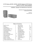
Figure 3: Air Coil Connection
Bulb (Must be
Installed and
Insulated)
Equalizer
Line
Suction Line
Line Set Installation
Figure 5 illustrates a typical installations of an air handler or
cased coil matched to an indoor compressor section. Table
A shows typical line-set diameters at various lengths. Lineset
lengths should be kept to a minimum and should always be
installed with care to avoid kinking. Line sets over 60 feet [18
meters] long are not recommended due to potential oil transport
problems and excessive pressure drop. If the line set is kinked
or distorted, and it cannot be formed back into its original
shape, the damaged portion of the line should be replaced. A
restricted line set will effect the performance of the system.
All brazing should be performed using nitrogen circulating
at 2-3 psi [13.8-20.7 kPa] to prevent oxidation inside the
tubing. All linesets should be insulated with a minimum
of 1/2” [13mm] thick closed cell insulation. All insulation
tubing should be sealed using a UV resistant paint or
covering to prevent deterioration from sunlight.
See compressor section IOM for refrigerant charge
information.
LT2
Sensor
TXV has internal
check valve
CAUTION!
CAUTION! Installation of a factory supplied liquid line
bi-directional filter drier is required. Never install a suction
line filter in the liquid line.
TXV (‘IN’ toward
compressor section)
Liquid Line
Sensing Bulb
IMPORTANT: DO NOT perform any brazing with the TXV
bulb attached to any line. After brazing operations have been
completed, clamp the TXV bulb securely on the suction line
at the 10 or 2 o’clock position with the strap provided in the
parts bag. Insulate the TXV sensing bulb and suction line
with the provided pressure sensitive insulation (size 4” x 7”).
IMPORTANT: TXV sensing bulb should be located on a
horizontal section of suction line, just outside of coil box.
IMPORTANT: Always protect TXV from heat when brazing.
IMPORTANT: TXV sensing bulb is shipped unattached.
Installer must attach bulb to suction line after brazing and
cooling line for proper unit operation.
NOTICE! The air coil should be thoroughly washed with a
filming agent, (dishwasher detergent like Cascade) to help
condensate drainage. Apply a 20 to 1 solution of detergent
and water. Spray both sides of coil, repeat and rinse
thoroughly with water. Care should be taken not to overflow
drain pan. Wash after connecting condensate line.
When passing refrigerant lines through a wall, seal
opening with silicon-based caulk. Avoid direct contact
with water pipes, duct work, floor joists, wall studs,
floors or other structural components that could transmit
compressor vibration. Do not suspend refrigerant tubing
from joists with rigid straps. Do not attach line set to the
wall. When necessary, use hanger straps with isolation
sleeves to minimize transmission of line set vibration to
the structure.
Installing the Indoor Coil and Lineset
Figure 3 shows the installation of the lineset and TXV to
a typical indoor coil. Braze the copper line set to the coil.
Nitrogen should be circulated through the system at 2-3 psi
[13.8-20.7 kPa] to prevent oxidation inside the refrigerant
tubing. Use a low silver phos-copper braze alloy on all brazed
connections.
11
Tranquility Air Handler (TAH)
R e v. : N o v. 1 9 , 2 0 1 2
Installation
Evacuation and Charging the Unit
LEAK TESTING - The refrigeration line set must be pressurized
and checked for leaks before evacuating and charging the unit.
To pressurize the line set, attach refrigerant gauges to the service
ports and add an inert gas (nitrogen or dry carbon dioxide) until
pressure reaches 60-90 psig [413-620 kPa]. Never use oxygen
or acetylene to pressure test. Use a good quality bubble solution
to detect leaks on all connections made in the field. Check the
service valve ports and stem for leaks. If a leak is found, repair it
and repeat the above steps. For safety reasons do not pressurize
system above 150 psig [1034 kPa]. System is now ready for
evacuation and charging.
Figure 4: Condensate Drain Trap
'2 127 23(5$7( 81,7 :,7+287
&21'(16$7( '5$,1 75$3
81,7
'2 127 29(57,*+7(1 '5$,1 ),77,1*
Condensate Drain Tubing
Consult local codes or ordinances for specific requirements.
IMPORTANT: When making drain fitting connections to the
drain pan, use a thin layer of Teflon paste, silicone or Teflon
tape and install hand tight.
IMPORTANT: When making drain fitting connections to drain
pan, do not overtighten. Overtightening fittings can split pipe
connections on the drain pan.
• Install drain lines so they do not block service access
to front of the unit. Minimum clearance of 24 inches is
required for filter, coil or blower removal and service
access.
• Make sure unit is level or pitched slightly toward primary
drain connection so that water will drain completely from
the pan (See Figure 4).
• Do not reduce drain line size less than connection size
provided on condensate drain pan.
• All drain lines must be pitched downward away from the
unit a minimum of 1/8” per foot of line to ensure proper
drainage.
• Do not connect condensate drain line to a closed or
open sewer pipe. Run condensate to an open drain or
outdoors.
• The drain line should be insulated where necessary to
prevent sweating and damage due to condensate forming
on the outside surface of the line.
• Make provisions for disconnecting and cleaning of the
primary drain line should it become necessary. Install
a 3 in. trap in the primary drain line as close to the unit
as possible. Make sure that the top of the trap is below
connection to the drain pan to allow complete drainage of
pan (See Figure 4).
• Auxiliary drain line should be run to a place where it will
be noticeable if it becomes operational. Occupant should
be warned that a problem exists if water should begin
running from the auxiliary drain line.
• Plug the unused drain connection with the plugs provided
in the parts bag, using a thin layer of Teflon paste, silicone
or Teflon tape to form a water tight seal.
• Test condensate drain pan and drain line after installation
is complete. Pour water into drain pan, enough to fill
drain trap and line. Check to make sure drain pan is
draining completely, no leaks are found in drain line
fittings, and water is draining from the termination of the
primary drain line.
12
81,7 0867 %( 6/,*+7/< ,1&/,1('
72:$5' '5$,1 &211(&7,21
It is always recommended that an auxiliary drain pan be
installed under a horizontally installed air handler.
Connect the auxiliary drain line to a separate drain line (no
trap is needed in this line) and terminate according to local
codes.
NOTE: DO NOT use a torch or flame near the
plastic drain pan coupling.
NOTE: DO NOT tighten the drain pipe excessively.
Support the condensate piping and traps outside
the unit to prevent strain on the drain connection.
Geothermal Heat Pump Systems
Tranquility Air Handler (TAH)
R e v. : N o v. 1 9 , 2 0 1 2
Installation
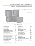
Figure 5: Typical Split/Air Handler Installation
Power
Disconnects
Insulated
Linesets
Low Voltage
PVC Condensate
with vented trap
Compressor Section
Air pad or Extruded
polystryene
13
Tranquility Air Handler (TAH)
R e v. : N o v. 1 9 , 2 0 1 2
Installation
AXM Control
The Tranquility® Digital Air handler (TAH Revision B) is
equipped with a communicating AXM board to allow
communication with the communicating compressor section
(TES/TEP) and communicating thermostat (ATC).
DIP #2: Dehumidification Mode - Provides selection of normal
or Dehumidification Fan Mode. In Dehumidification Mode, the
fan speed will be adjusted for Cooling. In Normal Mode, the
fan speed will be normal during Cooling.
On = Normal Fan Mode. Off = Dehumidification Mode
The AXM control allows either 4-wire connection with
Communicating DXM2 board and Communicating
ATC Thermostat. It can also be connected to a noncommunicating thermostat and compressor section using
up to 9-wires (plus additional if functionality requires). Please
see Thermostat section for more details.
Rest of the DIP switches are not used.
ACCESSORY CONNECTION / CONFIGURATION
2 Accessory outputs on AXM board only track blower
operation.
Other accessories are connected to the DXM2 board. Please
refer to DXM2 AOM for more details.
Figure 5: AXM Connections
Condensate
LT2
Sensor
Sensor
Fan Connections
Electric Heat
Connections
Accessory
outputs
that track
blower
operation
4-wire
connection
to DXM2
9-wire connection to non4-wire connection to
communicating thermostat/ communicating thermostat
compressor section
Low Air Temperature Sensor Installation
Tranquility® Digital Air Handlers are shipped with LT2 (Low
Air Temperature) sensor installed in the Air Handler (Figure
3) and connected to the AXM control. No additional action
required (do not clip the VIO wires).
Test Button
The test button puts the AXM into test mode, which
bypasses the soft start ramping profile and the blower
immediately ramps up to the nominal target speed.
FIELD SELECTABLE INPUTS
DIP SWITCHES
Note: In the following field configuration options, DIP
switches should only be moved when power is removed
from the DXM2 Control to ensure proper operation.
14
Geothermal Heat Pump Systems
Tranquility Air Handler (TAH)
R e v. : N o v. 1 9 , 2 0 1 2
Electrical - Thermostat Wiring
Thermostat Installation
The thermostat should be located on an interior wall in a
larger room, away from supply duct drafts. DO NOT locate
the thermostat in areas subject to sunlight, drafts or on
external walls. The wire access hole behind the thermostat
may in certain cases need to be sealed to prevent erroneous
temperature measurement. Position the thermostat back
plate against the wall so that it appears level and so the
thermostat wires protrude through the middle of the back
plate. Mark the position of the back plate mounting holes
and drill holes with a 3/16” (5mm) bit. Install supplied
anchors and secure plate to the wall. Thermostat wire must
be 18 AWG wire. Wire the appropriate thermostat as shown
in Figures 6 and 7 to the low voltage terminal strip on the
ECM control board. Practically any heat pump thermostat
will work with these units, provided it has the correct number
of heating and cooling stages.
Connection to Non-Communicating thermostat, AXM
communicating control in Tranquility® Digital Air Handler
and Tranquility® Digital Splits
Figure 7: Connection to Non-Communicating
thermostat and AXM communicating control
in Tranquility® Digital Air Handler
Non-Communicating
2 Cool / 3 Heat Thermostat
Compressor
Compressor Stage 2
Y1
Reversing Valve
24Vac Hot
O
Fan
24Vac Common
Dehumidification
(ATP32U04 Only)
Fault LED
4-Wire Connection ATC communicating thermostat and
DXM2 Communicating control in Tranquility® Digital Splits
AXM control in Tranquility® Digital Air Handler allows
4-wire connection with Communicating DXM2 board and
Communicating ATC Thermostat.
Figure 6: 4-Wire Connection to ATC communicating
thermostat, AXM Communicating control
and Tranquility® Digital Splits
iGate Thermostat
ATC32**
™
Communicating
TAH with
AXM Control
C
A+
Y2
Communicating
TAH AXM Control
Y1
Y2
O
G
C
DH
R
G
C
DH
L
AL1
R
C
A+
B24V
DXM2 In
Compressor
Section
C
A+
B24V
Thermostat Connections
C
24V Common for Control Circuit
R
24V Supply for Control Circuit
A+
Communications (Positive)
B–
Communications (Negative)
DXM2 in
Compressor
Section
C
A+
C
A+
C
A+
R
B-
B-
B-
B-
R
24V
24V
Thermostat Connections
C
24V Common for Control Circuit
R
24V Supply for Control Circuit
A+
Communications (Positive)
B–
Communications (Negative)
15
Tranquility Air Handler (TAH)
R e v. : N o v. 1 9 , 2 0 1 2
ECM Blower Control
The ECM fan is controlled directly by the DXM2/AXM
control board that converts thermostat inputs and CFM
settings to signals used by the ECM motor controller. To
take full advantage of the ECM motor features, an iGate™
communicating multi-stage thermostat should be used
(ATC32U**).
The AXM control maintains a selectable operating airflow
[CFM] for each heat pump operating mode. For each
operating mode there are maximum and minimum airflow
limits. See the ECM Blower Performance tables for the
maximum, minimum, and default operating airflows.
Airflow levels are selected using the configuration menus of
a communicating thermostat (ATC32U**) or diagnostic tool
(ACDU**). The configuration menus allow the installer to
independently select and adjust the operating airflow for each
of the operating modes. Air flow can be selected in 25 CFM
increments within the minimum and maximum limits shown in
Table 8. The blower operating modes include:
• First Stage Cooling (Y1 & O)
• Second Stage Cooling (Y1, Y2, & O)
• First Stage Cooling in Dehumidification Mode
(Y1, O, & Dehumid)
• Second Stage Cooling in Dehumidification Mode
(Y1, Y2, O, & Dehumid)
• First Stage Heating (Y1)
• Second Stage Heating (Y1 & Y2)
• Third Stage (Auxiliary) Heating (Y1, Y2, & W)
• Emergency Heating (W with no Y1 or Y2)
• Fan (G with no Y1, Y2, or W)
Special Note for AHRI Testing: To achieve rated airflow for
AHRI testing purposes, it is necessary to change the CFM
settings to rated airflow.
Figure 27: Airflow Configuration Screen on
Communicating Thermostat
AIRFLOW SELECTION
HEAT STAGE 1
HEAT STAGE 2
AUXILIARY HEAT
EMERGENCY HEAT
COOL STAGE 1
COOL STAGE 2
COOL DEHUMID 1
COOL DEHUMID 2
CONTINUOUS FAN
HEAT OFF DELAY
COOL OFF DELAY
PREVIOUS
The ECM motor includes “soft start” and “ramp down”
features. The soft start feature is a gentle increase of motor
rpm at blower start up. This creates a much quieter blower
start cycle.
The ramp down feature allows the blower to slowly decrease
rpm to a full stop at the end of each blower cycle. This
creates a much quieter end to each blower cycle and adds
overall unit efficiency.
The ramp down feature is eliminated during an ESD
(Emergency Shut Down) situation. When the DXM2 ESD
input is activated, the blower and all other control outputs are
immediately de-activated.
The duration of the “ramp down” periods are adjustable from
0 seconds to 255 seconds. This adjustment is available
in the Aiflow Selection screen using the communicating
thermostat or configuration/diagnostics tool, see Figure 27.
16
Geothermal Heat Pump Systems
CFM
600
750
850
850
525
700
425
550
350
60
30
NEXT
Tranquility Air Handler (TAH)
R e v. : N o v. 1 9 , 2 0 1 2
Blower Performance Data
Table 8:TAH Digital Standard Unit
Airflow in CFM with wet coil and clean air filter
Model
TAH
026
TAH
038
TAH
049
TAH
064
TAH
072
Max
ESP
(in. wg)
1.0
0.9
1.0
0.7
0.7
Fan
Motor
(hp)
1/2
1/2
1
1
1
Heating
Mode
Stg 2
Stg 1
Stg 2
Stg 1
Stg 2
Stg 1
Fan
Only
Mode
Default
700
525
550
425
750
600
350
850
Maximum
1000
800
800
600
1000
850
1000
1000
Minimum
600
450
550
400
600
450
300
700
Default
1050
800
850
650
1100
850
550
1350
Maximum
1500
1100
1200
900
1500
1100
1500
1500
Minimum
900
600
825
550
900
600
450
1350
Default
1400
1050
1100
850
1500
1150
700
1500
Maximum
2000
1500
1600
1200
2000
1500
2000
2000
Minimum
1200
900
1100
825
1200
900
600
1350
Default
1750
1300
1400
1050
1875
1450
875
1875
Maximum
2300
1900
2000
1500
2300
1900
2300
2300
Minimum
1500
1100
1375
1000
1500
1100
750
1500
Default
1900
1450
1650
1250
2000
1650
950
2000
Range
Cooling Mode
Dehumid Mode
Aux/
Emerg
Mode
Maximum
2300
2200
2000
1800
2300
2200
2300
2300
Minimum
1800
1350
1650
1250
1800
1350
900
1800
Airflow is controlled within 5% up to the Max ESP shown with wet coil
17
Tranquility Air Handler (TAH)
R e v. : N o v. 1 9 , 2 0 1 2
Electrical - Power Wiring
Figure 9: Remove Harness Plug
WARNING!
WARNING! Electrical shock hazard - Lock unit disconnect
switch in open position before servicing unit. Failure
to follow this warning could result in property damage,
personal injury, or death.
1. These Air Handlers are shipped from the factory wired
for 230 volts. The units may be wired for 208 or 115
volts. Follow instructions on unit wiring diagram located
on blower housing and in the Service Facts document
included with the unit.
2. The selection of wire and fuse sizes should be made
according to the Minimum Branch Circuit Ampacity and the
Maximum Overcurrent Device listed on the unit nameplate.
3. Field wiring diagrams for electric heaters and unit
accessories are shipped with the accessory.
4. Wiring must conform to National and Local codes.
5. Ground unit per local codes with good safety procedures.
Figure 10: Install Two Pin Jumper Plug
NOTE: If air handler is used with or without a
heater, the electrical entry hole as well as any other
cabinet penetrations must be sealed air-tight.
Wiring Instructions for 115v Conversion from 230 volt
1. Disconnect all power to the unit.
2. Disconnect Transformer primary orange wire from power
block T2 and insulate open end of wire. Connect the
white lead from transformer primary wire to power block
terminal T2. Note: (L2 will be used as Netural)
3. Remove plug in ECM power wiring harness (Fig. 9) and
Install 2 pin jumper plug provided in control box (Fig. 10).
Note: For 115v power only. Damage will occur to motor
with 230v power supply if 115v jumper is used.
NOTE: When supplementary heaters are installed,
inspect to insure that all packaging material has
been removed.
Table 4: Electric Table (115) 208/230
Model
Fan
Motor
FLA
Fan
Motor
HP
Max
Fan
ESP
Min Circ
Amp
(120)
208/230
Total
Unit
FLA
Max Fuse/
HACR
(120)
208/230
026
(7.7) 4.3
1/2
0.5
(7.8) 4.9
(7.7) 4.3
(15) 15
038
(7.7) 4.3
1/2
0.5
(7.8) 4.9
(7.7) 4.3
(15) 15
049
(12.8) 7
1
1
(14.4) 8.6
(12.8) 7
(25) 15
064
(12.8) 7
1
1
(14.4) 8.6
(12.8) 7
(25) 15
Dual Rated Voltate: (115) 208/230
Min/Max Voltage: 115: 114/132
Min/Max Voltage: 208/230: 197/254
18
Geothermal Heat Pump Systems
Tranquility Air Handler (TAH)
R e v. : N o v. 1 9 , 2 0 1 2
Electric Heat Installation
Overview
The AG Series Auxiliary Electric Heat mounts internally in
upflow (Figure 11) or downflow units and horizontal units.
Horizontal units are rated for zero clearance at the unit
and 1" clearance for first three feet of duct, vertical units
rated for zero clearance for both unit and duct. Downflow
units can not be located directly over a discharge register.
The discharge plenum must be constructed from non
combustible material. The AG electric heat contains a four
stage relay control board which activates the elements
directly via an internally wired low voltage harness. Low
voltage signals (W1 and W2) are staged from the AXM
control.
Vertical Upflow or Downflow and Horizontal Installation
1. Disconnect power to the unit
2. Remove blower access panels.
3. Clip wire-tie holding electric heat low voltage 3-wire
harness to discharge panel stiffener.
4. Remove blower mounting screws and then drop down
blower assembly as shown in Figure 12. Removal of
blower wires should not be necessary.
5. Install electric heat in discharge flange where blower
assembly has been removed using provided screws as
shown In Figure 13.
5.5 For downflow or horizontal right discharge units, the
air handler support bracket must be removed to reinstall the blower housing assembly. After re-installing
the blower housing, re-install the air handler support
bracket.
6. Re-install blower assembly, Figure 13, into electric heat
assembly using blower mounting screws. Check blower
wiring for proper wiring connections.
7. Route the low voltage harness through the provided
‘pie’ bushing and plug into electric heat control board
connector P2 as shown in Figure 18.
8. Install power conduit through unit corner post knockout
and attach conduit directly to the electric heat control
box.
9. Optional: AG**C kits only. Blower power may be supplied
from T3 & T4 CB5 breaker. Refer to wiring diagram
96B0143N01.
Figure 11: Typical air handler installation
Auxiliary electric heat
power supply knockout
opposite air coil
Electric Heat
Assembly
Disconnect (optional
refer to local code)
Air Coil
Route condiut thru cabinet and
connect to electric heat control
box. Seal to eliminate air leaks on
cabinet exterior.
Low voltage control
harness is prewired
on all distributor class units.
Figure 12: Blower removal
Figure 13: AG electric heat mounting and
blower re-installation
Locate electric heat assembly
on pins in discharge panel
and insert screws
Relocate blower in electric
heat assembly in same
manner
19
Tranquility Air Handler (TAH)
R e v. : N o v. 1 9 , 2 0 1 2
Electric Heat Wiring
Figure 14: Power Wiring, Dual Circuits, 15 and 20kw
Figure 15: Power Wiring, Single Circuit, 15, 20kw
2))
3
21
,QDQGN:XQLWV
WZRSRZHUFLUFXLWVDUH
HPSOR\HGWRUHGXFHZLUHV
VL]HDQGFRVWRIEUHDNHUV
/
3
2))
21
/
/
/
&RQGXLW
Wiring and Setup (all models)
1. Install power wiring and connect to power block or
circuit breakers. In 12, 15 or 20kW models two power
circuits may be used to reduce wiring and breaker
costs as in Figure 14. If a single circuit supply is
desired, install the optional single circuit accessory kit
(P/N 16B0002N02), as shown in Figure 15, that can be
obtained from your distributor.
2. Ensure unit airflow setting is above minimum airflow rating
for the electric heat model from Table 1.
3. Check staging jumpers for the application. Typically
only 5 kW (factory setting on all models except 10kW on
20kW models) is needed for first stage electric (W1) to
minimize electric demand. This staging can be adjusted
by moving the staging jumpers as shown in Figure 17.
Whatever is jumped to P1 pin 1 will be energized on
1st stage of electric heat, and P1-2 will be energized as
stage 2 electric heat. See Table C for staging options.
4. Mark the appropriate box of the electric heat model
installed on the additional serial plate on the exterior of
the unit.
5. Turn on the power to the unit and the auxiliary
electric heat.
Auxiliary Electric Heat Start-up
Put thermostat in emergency heat mode in manual mode on
ATC/ACD (see figure #) and setpoint to high setting. Unit will
require 15-20 seconds before engaging emergency heat mode
stage 1 (W1) and then another 15-20 seconds to engage
stage 2 (W2) when in ‘Test mode’. Verify proper electric heat
operation. Exit manual mode for normal operation.
Figure 16: Power Wiring, 4, 5, 8, and 10kw
Figure 17: Staging Jumpers
Staging Example on a 15kW unit W1 (first stage) has
5kW (‘ER1’ 5kW & ‘ER4’ 0kW) and W2 (second stage)
will have 10kW (‘ER2 & 3’ 5kW each)
blank
W1
W2 24V
Ora
AG Electric Heat
Relay Board
P2
P1
4 3 2 1
Low Voltage Connector
(from Unit Control Board)
Factory Staging
(see Table 2)
MANUAL OPERATING MODE
ER4
Y1
Y1
Y2
W
O
G
H
DH
ECM
PUMP
TEST
COMM
COMM OUTPUT
OUTPUT
COMM OUTPUT
COMM OUTPUT
COMM OUTPUT
COMM OUTPUT
COMM OUTPUT
COMM OUTPUT
AIRFLOW
SPEED
MODE
SELECT OPTION
PREVIOUS
20
OFF
OFF
OFF
OFF
OFF
OFF
OFF
0
0%
OFF
Tan
Com
ER3
Com
NO
ER2
Com
NO
NO
Side View as seen in Control Box
SELECT
Geothermal Heat Pump Systems
ER1
Com
NO
Tan
Ora
P1
P2
4 3 2 1
Tranquility Air Handler (TAH)
R e v. : N o v. 1 9 , 2 0 1 2
Electric Heat Wiring and Staging Options
Figure 18: Low Voltage Harness Connection
Table 1: AG Electric Heat Ratings
Auxiliary
Electric
Heat
Model
TAH Models
kW Rating
Btuh Rating
240V
208V
240V
208V
Minimum
CFM
Required
AGM4C
3.8
2.9
13000
9900
500
AGM5C
4.8
3.6
16300 12300
500
AGM8C
7.6
5.7
25900 19400
650
AGM10C
9.6
7.2
32700 24600
650
AGL4C
3.8
2.9
13000
500
026
038
049064
9900
AGL10C
9.6
7.2
32700 24600
1300
AGL15C
14.4
10.8
49100 36900
1350
AGL20C
19.2
14.4
65500 49200
1350
Black area denotes compatibility
Note: Horizontal units rated for zero clearance unit and 1” clearance
for the first three feet of duct,
Vertical units rated for zero clearance for both unit and duct.
Table 2: AG Electric Heat Staging Options
Staging in kW
Jumper 1-3, 2-4†
Stage 1
Stage 2
Auxiliary Electric
Heat Model
Staging
Options
Factory
Settings
Stage 1
AGM4C
4
4
4
0
4
0
4
0
AGM5C
5
5
5
0
5
0
5
0
AGM8C
4 or 8
4
4
4
4
4
8
0
AGM10C
5 or 10
5
5
5
5
5
10
0
Jumper 1-4, 2-3†
Stage 1
Stage 2
Jumper 1-2-3
Stage 1
Stage 2
AGL4C
4
4
4
0
4
0
4
0
AGL10C
5 or 10
5
5
5
5
5
10
0
AGL15C
5, 10 or 15
5
5
10
10
5
15
0
AGL20C
5, 10, 15 or 20
10
10
10
10
10
15
5
† Factory jumper setting
Table 3: AG Electric Heat Electrical Data
Unit Model
Maximum Breaker
Size
Head Kit
Model
Supply
Heater
Amps
240
Heater
Amps
208
Blower
FLA
240 V
208 V
240 V
208 V
AGM4C
SINGLE
15.8
14
4.3
25
23
25
25
AGM 5C
SINGLE
20
17.3
4.3
30
27
30
30
AGM 8C
SINGLE
31.7
27.5
4.3
45
40
45
40
Minimum Circuit Amps
TAH026
AGM 10C
SINGLE
40
34.7
4.3
55
49
60
50
AGL4C
SINGLE
15.8
14
4.3
28.5
26.25
30
30
AGL10C
SINGLE
40
34.7
4.3
59
52
60
60
DUAL L1/L2
40
34.7
0
50
43
50
45
TAH038
AGL15C
TAH049 and
TAH060
L3/L4
20
17.3
4.3
34
30
35
30
AGL4C
SINGLE
15.8
14
7
28.5
26.25
30
30
AGL10C
SINGLE
40
34.7
7.0
59
52
60
60
DUAL L1/L2
40
34.7
0.0
50
43
50
45
L3/L4
20
17.3
7.0
34
30
35
30
DUAL L1/L2
40
34.7
0.0
50
43
50
45
L3/L4
40
34.7
7.0
59
52
60
60
AGL15C
AGL20C
All heaters rated single phase 208-240V 60Hz
All models 15kW or larger feature internal circuit breakers
All Fuses UL Class K general purpose
21
Tranquility Air Handler (TAH)
R e v. : N o v. 1 9 , 2 0 1 2
Typical Wiring Diagram - 96B0005N55
22
Geothermal Heat Pump Systems
Tranquility Air Handler (TAH)
R e v. : N o v. 1 9 , 2 0 1 2
Unit & System Checkout
❑
WARNING!
WARNING! Electrical shock hazard - Lock unit disconnect
switch in open position before servicing unit. Failure
to follow this warning could result in property damage,
personal injury, or death.
After installation has been completed, it is recommended that
the Air Handler be checked against the following checklist:
CHECKOUT PROCEDURE
❑
Power: Make sure power is “OFF” at power
disconnect switch.
❑
Field Wiring: Check all field wiring for tight
connections. See that grounding of unit is in accord
with code
❑
Unit Suspension: Make sure unit suspension (if
used) is secure and that there are no tools or loose
debris in, around or on top of the unit.
❑
❑
❑
❑
❑
❑
Ducts: Check all duct outlets; they must be open and
unrestricted.
Drain Lines: Check drain lines and be sure all joints
are tight.
Drain Pan: Make sure secondary drain pan is installed.
Power Supply: Check power supply for correct
requirements per unit nameplate.
Filters: Check filters for proper size. Inform owner
of proper procedure for removal and reinstallation.
Operation: Energize the system and carefully
observe its operation; make any necessary
adjustment.
Procedure: Instruct owner, engineer (if possible) on
proper operating procedure and leave Use and Care
Manual with owner.
MAINTENANCE
WARNING!
WARNING! These instructions are intended as
an aid to qualified licensed service personnel for
proper installation, adjustment and operation of
this unit. Read these instructions thoroughly before
attempting installation or operation. Failure to follow
these instructions may result in improper installation,
adjustment, service or maintenance possibly resulting in
property damage, personal injury or death.
Indoor Coil - Drain Pipe - Drain Line
Inspect the indoor coil once each year for cleanliness and
clean as necessary. In some cases, it may be necessary to
remove the filter and check the return side of the coil with
a mirror and flashlight.
IMPORTANT: Do not use caustic household drain cleaners
or bleach in the condensate pan or near the indoor coil.
Drain cleaners will quickly damage the indoor coil.
For continuing high performance and to minimize possible
equipment failure, it is essential that annual maintenance be
performed on this equipment. Consult your local dealer as to
the availability of a maintenance contract.
Air Filter
Check the system filter every ninety days or as often as found
to be necessary and if obstructed, clean or replace at once.
IMPORTANT: Do not operate the system without a filter in
place.
23
Tranquility Air Handler (TAH)
R e v. : N o v. 1 9 , 2 0 1 2
Warranty
&/,0$7(0$67(5,1&
/,0,7('(;35(66:$55$17</,0,7$7,212)5(0(',(6$1'/,$%,/,7<)25
5(6,'(17,$/&/$66352'8&76:,7+/$%25$//2:$1&(
,WLVH[SUHVVO\XQGHUVWRRGWKDWXQOHVVDVWDWHPHQWLVVSHFL¿FDOO\LGHQWL¿HGDVDZDUUDQW\VWDWHPHQWVPDGHE\&OLPDWH0DVWHU,QFD'HODZDUHFRUSRUDWLRQ³&0´RULWVUHSUHVHQWDWLYHVUHODWLQJWR&0¶VSURGXFWVZKHWKHURUDOZULWWHQRUFRQWDLQHG
LQDQ\VDOHVOLWHUDWXUHFDWDORJRUDJUHHPHQWDUHQRWH[SUHVVZDUUDQWLHVDQGGRQRWIRUPDSDUWRIWKHEDVLVRIWKHEDUJDLQEXWDUHPHUHO\&0¶VRSLQLRQRUFRPPHQGDWLRQRI&0¶VSURGXFWV(;&(37$663(&,),&$//<6(7)257+
+(5(,17+(5(,612(;35(66:$55$17<$672$1<2)&0¶6352'8&76&00$.(612:$55$17<$*$,167/$7(17'()(&76&00$.(612:$55$17<2)0(5&+$17$%,/,7<2)7+(
*22'6252)7+(),71(662)7+(*22'6)25$1<3$57,&8/$5385326(
*5$172)/,0,7('(;35(66:$55$17<
&0ZDUUDQWVLWV5HVLGHQWLDO&ODVVSURGXFWVSXUFKDVHGDQGUHWDLQHGLQWKH8QLWHG6WDWHVRI$PHULFDDQG&DQDGDWREHIUHHIURPGHIHFWVLQPDWHULDODQGZRUNPDQVKLSXQGHUQRUPDOXVHDQGPDLQWHQDQFHDVIROORZV$LUFRQGLWLRQLQJKHDWLQJ
DQGRUKHDWSXPSXQLWVEXLOWRUVROGE\&0³&08QLWV´IRUWHQ\HDUVIURPWKH:DUUDQW\,QFHSWLRQ'DWHDVGH¿QHGEHORZ7KHUPRVWDWVDX[LOLDU\HOHFWULFKHDWHUVDQGJHRWKHUPDOSXPSLQJPRGXOHVEXLOWRUVROGE\&0ZKHQLQVWDOOHG
ZLWK&08QLWVIRUWHQ\HDUVIURPWKH:DUUDQW\,QFHSWLRQ'DWHDVGH¿QHGEHORZDQG2WKHUDFFHVVRULHVDQGSDUWVEXLOWRUVROGE\&0ZKHQLQVWDOOHGZLWK&08QLWVIRURQH\HDUIURPWKHGDWHRIVKLSPHQWIURP&07KH³:DUUDQW\
,QFHSWLRQ'DWH´VKDOOEHWKHGDWHRIRULJLQDOXQLWLQVWDOODWLRQRUVL[PRQWKVIURPGDWHRIXQLWVKLSPHQWIURP&0ZKLFKHYHUFRPHV¿UVW
7RPDNHDFODLPXQGHUWKLVZDUUDQW\SDUWVPXVWEHUHWXUQHGWR&0LQ2NODKRPD&LW\2NODKRPDIUHLJKWSUHSDLGQRODWHUWKDQQLQHW\GD\VDIWHUWKHGDWHRIWKHIDLOXUHRIWKHSDUWLI&0GHWHUPLQHVWKHSDUWWREHGHIHFWLYHDQGZLWKLQ&0¶V
/LPLWHG([SUHVV:DUUDQW\&0VKDOOZKHQVXFKSDUWKDVEHHQHLWKHUUHSODFHGRUUHSDLUHGUHWXUQVXFKWRDIDFWRU\UHFRJQL]HGGLVWULEXWRUGHDOHURUVHUYLFHRUJDQL]DWLRQ)2%&02NODKRPD&LW\2NODKRPDIUHLJKWSUHSDLG7KHZDUUDQW\RQ
DQ\SDUWUHSDLUHGRUUHSODFHGXQGHUZDUUDQW\H[SLUHVDWWKHHQGRIWKHRULJLQDOZDUUDQW\SHULRG
7KLV/LPLWHG([SUHVV:DUUDQW\VKDOOFRYHUWKHODERULQFXUUHGE\&0DXWKRUL]HGVHUYLFHSHUVRQQHOLQFRQQHFWLRQZLWKWKHLQVWDOODWLRQRIDQHZRUUHSDLUHGZDUUDQW\SDUWWKDWLVFRYHUHGE\WKLV/LPLWHG([SUHVV:DUUDQW\RQO\WRWKHH[WHQW
VSHFL¿FDOO\VHWIRUWKLQWKHWKHQH[LVWLQJODERUDOORZDQFHVFKHGXOHSURYLGHGE\&0¶V:DUUDQW\'HSDUWPHQWDQGRQO\DVIROORZV&08QLWVIRU¿YH\HDUVIURPWKH:DUUDQW\,QFHSWLRQ'DWH7KHUPRVWDWVDX[LOLDU\HOHFWULFKHDWHUVDQG
JHRWKHUPDOSXPSLQJPRGXOHVEXLOWRUVROGE\&0ZKHQLQVWDOOHGZLWK&08QLWVIRU¿YH\HDUVIURPWKH:DUUDQW\,QFHSWLRQ'DWH$FWXDO/DERUFRVWVDUHQRWFRYHUHGE\WKLV/LPLWHG([SUHVV:DUUDQW\WRWKHH[WHQWWKH\H[FHHGWKHDPRXQW
DOORZHGXQGHUVDLGDOORZDQFHVFKHGXOHWKH\DUHQRWVSHFL¿FDOO\SURYLGHGIRULQVDLGDOORZDQFHVFKHGXOHWKH\DUHQRWWKHUHVXOWRIZRUNSHUIRUPHGE\&0DXWKRUL]HGVHUYLFHSHUVRQQHOWKH\DUHLQFXUUHGLQFRQQHFWLRQZLWKDSDUWQRWFRYHUHGE\
WKLV/LPLWHG([SUHVV:DUUDQW\RUWKH\DUHLQFXUUHGPRUHWKDQWKHWLPHSHULRGVVHWIRUWKLQWKLVSDUDJUDSKDIWHUWKH:DUUDQW\,QFHSWLRQ'DWH
7KLVZDUUDQW\GRHVQRWFRYHUDQGGRHVQRWDSSO\WR$LU¿OWHUVIXVHVUHIULJHUDQWÀXLGVRLO3URGXFWVUHORFDWHGDIWHULQLWLDOLQVWDOODWLRQ$Q\SRUWLRQRUFRPSRQHQWRIDQ\V\VWHPWKDWLVQRWVXSSOLHGE\&0UHJDUGOHVVRIWKHFDXVHRIWKH
IDLOXUHRIVXFKSRUWLRQRUFRPSRQHQW3URGXFWVRQZKLFKWKHXQLWLGHQWL¿FDWLRQWDJVRUODEHOVKDYHEHHQUHPRYHGRUGHIDFHG3URGXFWVRQZKLFKSD\PHQWWR&0RUWRWKHRZQHU¶VVHOOHURULQVWDOOLQJFRQWUDFWRULVLQGHIDXOW3URGXFWV
VXEMHFWHGWRLPSURSHURULQDGHTXDWHLQVWDOODWLRQPDLQWHQDQFHUHSDLUZLULQJRUYROWDJHFRQGLWLRQV3URGXFWVVXEMHFWHGWRDFFLGHQWPLVXVHQHJOLJHQFHDEXVH¿UHÀRRGOLJKWQLQJXQDXWKRUL]HGDOWHUDWLRQPLVDSSOLFDWLRQFRQWDPLQDWHG
RUFRUURVLYHDLURUOLTXLGVXSSO\RSHUDWLRQDWDEQRUPDODLURUOLTXLGWHPSHUDWXUHVRUÀRZUDWHVRURSHQLQJRIWKHUHIULJHUDQWFLUFXLWE\XQTXDOL¿HGSHUVRQQHO0ROGIXQJXVRUEDFWHULDGDPDJHV&RUURVLRQRUDEUDVLRQRIWKHSURGXFW
3URGXFWVVXSSOLHGE\RWKHUV3URGXFWVZKLFKKDYHEHHQRSHUDWHGLQDPDQQHUFRQWUDU\WR&0¶VSULQWHGLQVWUXFWLRQV3URGXFWVZKLFKKDYHLQVXI¿FLHQWSHUIRUPDQFHDVDUHVXOWRILPSURSHUV\VWHPGHVLJQRULPSURSHUDSSOLFDWLRQ
LQVWDOODWLRQRUXVHRI&0¶VSURGXFWVRU(OHFWULFLW\RUIXHOFRVWVRUDQ\LQFUHDVHVRUXQUHDOL]HGVDYLQJVLQVDPHIRUDQ\UHDVRQZKDWVRHYHU
7KLV/LPLWHG([SUHVV:DUUDQW\SURYLGHVWKHOLPLWHGODERUDOORZDQFHFRYHUDJHDVVHWIRUWKDERYH2WKHUZLVH&0LVQRWUHVSRQVLEOHIRU7KHFRVWVRIDQ\ÀXLGVUHIULJHUDQWRUV\VWHPFRPSRQHQWVVXSSOLHGE\RWKHUVRUDVVRFLDWHGODERUWRUHSDLU
RUUHSODFHWKHVDPHZKLFKLVLQFXUUHGDVDUHVXOWRIDGHIHFWLYHSDUWFRYHUHGE\&0¶V/LPLWHG([SUHVV:DUUDQW\7KHFRVWVRIODERUUHIULJHUDQWPDWHULDOVRUVHUYLFHLQFXUUHGLQGLDJQRVLVDQGUHPRYDORIWKHGHIHFWLYHSDUWRULQREWDLQLQJDQG
UHSODFLQJWKHQHZRUUHSDLUHGSDUW7UDQVSRUWDWLRQFRVWVRIWKHGHIHFWLYHSDUWIURPWKHLQVWDOODWLRQVLWHWR&0RURIWKHUHWXUQRIWKDWSDUWLIQRWFRYHUHGE\&0¶V/LPLWHG([SUHVV:DUUDQW\RU7KHFRVWVRIQRUPDOPDLQWHQDQFH
7KLV/LPLWHG([SUHVV:DUUDQW\DSSOLHVWR&05HVLGHQWLDO&ODVVSURGXFWVRUGHUHGIURP&0RQRUDIWHU0D\WKLVZRXOGJHQHUDOO\LQFOXGH&08QLWVZLWKVHULDOQXPEHUVEHJLQQLQJZLWK³1´DQGKLJKHUDQGLVQRWUHWURDFWLYHWRDQ\
SURGXFWVRUGHUHGIURP&0SULRUWR0D\WKLVZRXOGJHQHUDOO\LQFOXGH&08QLWVZLWKVHULDOQXPEHUVEHJLQQLQJZLWK³1´DQGORZHU,I\RXDUHXQVXUHLIWKLV/LPLWHG([SUHVV:DUUDQW\DSSOLHVWRWKHSURGXFW\RXKDYHSXUFKDVHG
FRQWDFW&0DWWKHSKRQHQXPEHURUDGGUHVVUHÀHFWHGEHORZ
/LPLWDWLRQ7KLV/LPLWHG([SUHVV:DUUDQW\LVJLYHQLQOLHXRIDOORWKHUZDUUDQWLHV,IQRWZLWKVWDQGLQJWKHGLVFODLPHUVFRQWDLQHGKHUHLQLWLVGHWHUPLQHGWKDWRWKHUZDUUDQWLHVH[LVWDQ\VXFKH[SUHVVZDUUDQW\LQFOXGLQJZLWKRXWOLPLWDWLRQDQ\
H[SUHVVZDUUDQWLHVRUDQ\LPSOLHGZDUUDQWLHVRI¿WQHVVIRUSDUWLFXODUSXUSRVHDQGPHUFKDQWDELOLW\VKDOOEHOLPLWHGWRWKHGXUDWLRQRIWKH/LPLWHG([SUHVV:DUUDQW\
/,0,7$7,212)5(0(',(6
,QWKHHYHQWRIDEUHDFKRIWKH/LPLWHG([SUHVV:DUUDQW\&0ZLOORQO\EHREOLJDWHGDW&0¶VRSWLRQWRUHSDLUWKHIDLOHGSDUWRUXQLWRUWRIXUQLVKDQHZRUUHEXLOWSDUWRUXQLWLQH[FKDQJHIRUWKHSDUWRUXQLWZKLFKKDVIDLOHG,IDIWHUZULWWHQQRWLFH
WR&0¶VIDFWRU\LQ2NODKRPD&LW\2NODKRPDRIHDFKGHIHFWPDOIXQFWLRQRURWKHUIDLOXUHDQGDUHDVRQDEOHQXPEHURIDWWHPSWVE\&0WRFRUUHFWWKHGHIHFWPDOIXQFWLRQRURWKHUIDLOXUHDQGWKHUHPHG\IDLOVRILWVHVVHQWLDOSXUSRVH&0VKDOO
UHIXQGWKHSXUFKDVHSULFHSDLGWR&0LQH[FKDQJHIRUWKHUHWXUQRIWKHVROGJRRGV6DLGUHIXQGVKDOOEHWKHPD[LPXPOLDELOLW\RI&07+,65(0('<,67+(62/($1'(;&/86,9(5(0('<2)7+(%8<(525385&+$6(5
$*$,167&0)25%5($&+2)&2175$&7)257+(%5($&+2)$1<:$55$17<25)25&0¶61(*/,*(1&(25,1675,&7/,$%,/,7<
/,0,7$7,212)/,$%,/,7<
&0VKDOOKDYHQROLDELOLW\IRUDQ\GDPDJHVLI&0¶VSHUIRUPDQFHLVGHOD\HGIRUDQ\UHDVRQRULVSUHYHQWHGWRDQ\H[WHQWE\DQ\HYHQWVXFKDVEXWQRWOLPLWHGWRDQ\ZDUFLYLOXQUHVWJRYHUQPHQWUHVWULFWLRQVRUUHVWUDLQWVVWULNHVRU
ZRUNVWRSSDJHV¿UHÀRRGDFFLGHQWVKRUWDJHVRIWUDQVSRUWDWLRQIXHOPDWHULDORUODERUDFWVRI*RGRUDQ\RWKHUUHDVRQEH\RQGWKHVROHFRQWURORI&0&0(;35(66/<',6&/$,06$1'(;&/8'(6$1</,$%,/,7<)25
&216(48(17,$/25,1&,'(17$/'$0$*(,1&2175$&7)25%5($&+2)$1<(;35(6625,03/,(':$55$17<25,17257:+(7+(5)25&0¶V1(*/,*(1&(25$6675,&7/,$%,/,7<
&OLPDWH0DVWHU,QF&XVWRPHU6HUYLFH6:WK6WUHHW2NODKRPD&LW\2NODKRPDHVHUYLFH#FOLPDWHPDVWHUFRP
2%7$,1,1*:$55$17<3(5)250$1&(
1RUPDOO\WKHGHDOHURUVHUYLFHRUJDQL]DWLRQZKRLQVWDOOHGWKHSURGXFWVZLOOSURYLGHZDUUDQW\SHUIRUPDQFHIRUWKHRZQHU6KRXOGWKHLQVWDOOHUEHXQDYDLODEOHFRQWDFWDQ\&0UHFRJQL]HGGLVWULEXWRUGHDOHURUVHUYLFHRUJDQL]DWLRQ,IDVVLVWDQFHLV
UHTXLUHGLQREWDLQLQJZDUUDQW\SHUIRUPDQFHZULWHRUFDOO
5HY
3DUW1R53
127(6RPHVWDWHVRU&DQDGLDQSURYLQFHVGRQRWDOORZOLPLWDWLRQVRQKRZORQJDQLPSOLHGZDUUDQW\ODVWVRUWKHOLPLWDWLRQRUH[FOXVLRQVRIFRQVHTXHQWLDORULQFLGHQWDOGDPDJHVVRWKHIRUHJRLQJH[FOXVLRQVDQGOLPLWDWLRQVPD\QRWDSSO\WR\RX
7KLVZDUUDQW\JLYHV\RXVSHFL¿FOHJDOULJKWVDQG\RXPD\DOVRKDYHRWKHUULJKWVZKLFKYDU\IURPVWDWHWRVWDWHDQGIURP&DQDGLDQSURYLQFHWR&DQDGLDQSURYLQFH
3OHDVHUHIHUWRWKH&0,QVWDOODWLRQ2SHUDWLRQDQG0DLQWHQDQFH0DQXDOIRURSHUDWLQJDQGPDLQWHQDQFHLQVWUXFWLRQV
Geothermal Heat Pump Systems
24
Tranquility Air Handler (TAH)
R e v. : N o v. 1 9 , 2 0 1 2
Notes
25
Tranquility Air Handler (TAH)
R e v. : N o v. 1 9 , 2 0 1 2
Revision History
Page #
Description
Nov. 19, 2012
Various
AXM Info. Added
May 2, 2012
7
Dec. 13, 2010
15, 16
Sept 29, 2010
17
Electrical Data Updated
May 1, 2010
All
First Published
‘Return Air Opening’ Added to Dimensional Drawing
Revised Installation Info. and ECM diagram
R
AI
BR
I
HE
AT P U M P S
A
TO
NE
WATER
TO
IFIED TO ARI A
RT
S
C
CE
NG WITH
LYI
MP
O
IR
MANUFACT
UR
ER
Date
IS
ST
AND
3
ARD 1
-1
R
O
25
6
ISO 9001:2008
Certified
Quality: First & Always
7300 S.W. 44th Street
Oklahoma City, OK 73179
*97B0101N01*
97B0101N01
Phone: 405-745-6000
Fax: 405-745-6058
climatemaster.com
cmdealernet.com
ClimateMaster works continually to improve its products. As a result, the design and specifications of each product at the time for order may be
changed without notice and may not be as described herein. For specific information on the current design and specifications go to cmdealernet.com. Statements and other information contained herein are not express warranties and do not form the basis of any bargain between the
parties, but are merely ClimateMaster’s opinion or commendation of its products.
The management system governing the manufacture of ClimateMaster’s products is ISO 9001:2008 certified.
© ClimateMaster, Inc. 2010
26
Geothermal Heat Pump Systems