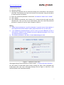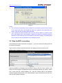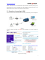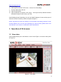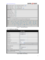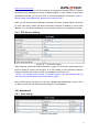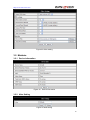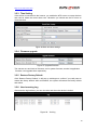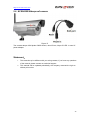
1
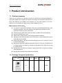
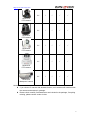
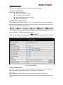
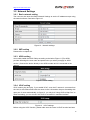
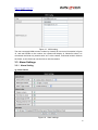
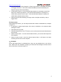
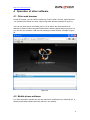
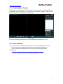
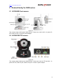
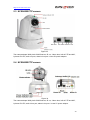
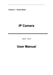
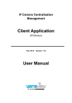
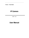
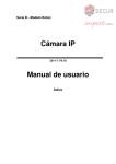
Dear users, the configuration for this camera is professional, so please read the user manual carefully before using the camera. IP Camera (B series) User manual 2012-11 V4.19 Statement If the user manual can not help you to solve the problem, please call our technology center about the solutions. We will update the content for the new functions without notice. Notice 1、 Installation Environment , Keep away from the places for high-temperature, heat source and direct sunlight; , Keep away from water and when get wet, cut off the power immediately. , Avoid to use in damp environment, the reference range for operation humidity is below , Avoid to use in overheating and too cold environment, the reference range for operation 85%RH. temperature is -10℃~ +50℃. , Please install it horizontally or wall mounting, avoid to strenuous vibration place and not put other equipments onto the item 2、 Transport and Handling , The package is well-designed to ensure the security during the delivery, so please do not change the package at random. , Do not move the ip cameras from overheated to supercooled condition frequently, otherwise it will frost and shorten the service life. , Do not move the item when is power on, otherwise the main board might be damaged. Notice: 1. Please check the power supply before it is working 2. Be careful not to bang the camera or subject it to strong impacts or shocks. 3. Do not directly touch the optical components for the image sensor, if necessary, please place a clean and moistened cloth with alcohol and wipe the dirt gently; When not in use, please place the dust cover on to the item to protect the image sensor. 4. Do not aim the camera directly into the sun or at other intense light sources that could affect the image quality (it is not the problem for the ip camera), also shorten the service life for the image sensor. 5. Keep away from laser when it is working, otherwise the image sensor can be damaged. 6. If the equipment is not working properly, please contact the store or the service center, do not disassemble or modify the equipment in any way. (Problems caused by unauthorized modification or repair should be at your own risk.) http://www.wansview.com Index 1 2 3 PRODUCT INTRODUCTION ......................................................................................................4 1.1 PRODUCT SUMMARY .................................................................................................................4 1.2 PACKAGE FOR TYPICAL PRODUCTION ........................................................................................4 INSTALLATION GUIDE ...............................................................................................................6 2.1 OPERATION OF CONNECTING TO LAN.......................................................................................6 2.2 STEP FOR WIFI CONNECTING ....................................................................................................8 2.3 OPERATION OF CONNECTING TO WAN ......................................................................................9 OPERATION OF IE BROWSER ...............................................................................................10 3.1 VIEW VIDEO ............................................................................................................................10 3.2 NETWORK SETTINGS...............................................................................................................12 3.2.1 Basic network setting .........................................................................................................12 3.2.2 WIFI setting .......................................................................................................................12 3.2.3 ADSL setting ......................................................................................................................12 3.2.4 UPnP setting......................................................................................................................12 3.2.5 DDNS Setting.....................................................................................................................13 3.2.6 3.3 3.3.1 Alarm Setting .....................................................................................................................14 3.3.2 Mail Service Setting ...........................................................................................................16 3.3.3 FTP Service Setting ...........................................................................................................17 3.4 5 ADVANCED .............................................................................................................................17 3.4.1 User Setting .......................................................................................................................17 3.4.2 Multi-Device Setting ..........................................................................................................18 3.4.3 Other settings.....................................................................................................................18 3.5 4 MSN setting........................................................................................................................14 ALARM SETTINGS ...................................................................................................................14 MAINTAIN ...............................................................................................................................19 3.5.1 Device Information ............................................................................................................19 3.5.2 Alias Setting .......................................................................................................................19 3.5.3 Time Setting .......................................................................................................................20 3.5.4 Firmware upgrade .............................................................................................................20 3.5.5 Restore Factory Default.....................................................................................................20 3.5.6 User browsing Log.............................................................................................................20 OPERATION OF OTHER SOFTWARE ...................................................................................21 4.1 OTHER WEB BROWSER ............................................................................................................21 4.2 MOBILE PHONE SOFTWARE .....................................................................................................21 4.3 CENTRALIZATION CONTROL ...................................................................................................22 4.4 OTHER SOFTWARE ..................................................................................................................22 PRODUCT FAMILY FOR NCB SERIES .................................................................................23 5.1 NCB546W CARD CAMERA .....................................................................................................23 5.2 NCB541W PTZ CAMERA .......................................................................................................23 5.3 NCB545W PTZ CAMERA .......................................................................................................24 2 http://www.wansview.com 5.4 NCB540W PTZ CAMERA .......................................................................................................24 5.5 NCB547W PTZ CAMERA .......................................................................................................25 5.6 NCB543W WATERPROOF CAMERA .........................................................................................26 3 http://www.wansview.com 1 Product introduction 1.1 Product summary Thank you for choosing our company’s B series IP camera, the IP Camera combines a high quality digital video camera with network connectivity and a powerful web server to bring clear video to your desktop from anywhere on your local network or over the Internet. It is very suitable for family, shops, office building and so on. Main features for B series: ♦ The video is compressed by MJPEG. There are VGA/QVGA/QQVGA three video resolutions optional. User can changes some parameters according to their ♦ ♦ ♦ ♦ ♦ ♦ demands to satisfy his own visual prefer; Infrared LED for night vision covers 5m area, to realize 24 hours monitoring; Support mobile phone to view; Support 802.11b/g/n protocol, can build up wireless monitoring; Alarming record can be stored by email, FTP server. External alarm will be active when detecting unusuality; Built in web server,All data is transferred through one port; it is easy for user to do the network setting; Manufacture attached a label at the bottom of each IP Camera, it include Device ID, DDNS. When IP Camera is connected to the internet, this URL can be used ♦ ♦ to visit the device; Manufacturer provides free software, support Multi-view, Long time recording, video playback etc; Manufacturer provides free mobile phone software. 1.2 Package for typical production Accessory Type Power adaptor CD Cable 5V √ √ Stand of plastic √ Antenna Built-in NCB546W Card camera 4 http://www.wansview.com 5V √ √ √ √ 5V √ √ √ √ 5V √ √ √ √ 5V √ √ √ √ 5V √ √ √ √ NCB541W PTZ camera NCB545W PTZ camera NCB540W PTZ camera NCB547W PTZ camera NCB543W Waterproof camera Notice: ♦ ♦ If you choose IP camera with wireless function, so it includes wifi module inside the camera and antenna in package. Please check carefully if all listed items are included in the package, if anything missing, please contact vendor in time. 5 http://www.wansview.com 2 Installation guide 2.1 Operation of connecting to LAN Power on the IP camera(please check carefully the voltage of power adaptor, don’t insert incorrect power, otherwise it will damage the device), connect IP camera to router by network cable, meanwhile, connect computer to the same router, example of figure 1. Figure 1 Insert CD to computer driver, double click “BSearch_en.exe” in the CD, will pop up the interface as figure 2, please operate as the following steps: Figure 2 6 http://www.wansview.com 1) Click ‘Search (F3)’; 2) Choose a camera; 3) Change the ip address of the ip camera according to the information in the red frame on the left. The numbers in the red circle should not be the same. Http port should be a number between 80~65535; 4) Enter user name and password for the device, the default is “admin” and “123456”; 5) Click ‘update’; 6) After updating successfully, click “Search (F3)”, choose the device again and click “Browse (F4)”. Then you can run the web browser, enter user name and password and login IP camera to view the video, example of figure 3. Notice: 1) Please check carefully the “Local PC information” in top left corner of the interface, if the computer has several network cards, please selects the one you are using. 2) If you installed the firewall software in your PC, when you run the BSearch_en.exe, it may pop up a window to say “whether you want to block this program or not”, then you should choose not to block。 3) The default ip address is 192.168.0.178 and default http port is 80。 Figure 3 Interface for view video We suggest using IE kernel browser to view the video (it can provide more functions), but user needs to install video player before viewing the video. Click “download and install player (first use)” link, it will popup dialogue box as Figure 4, click Run, it will download player and install automatically. 7 http://www.wansview.com Figure 4 Notice: ♦ You can hold on reset button on the camera for 10 seconds to restore factory default if you forget user name and password, during the process, don’t disconnect the power, otherwise the camera maybe damaged; ♦ If the camera has status indicator LED, you can view the status of camera via the LED: slow flicker( every two seconds), indicate the camera is searching network; flicker(one to two times per second) indicate it uses wired network; fast flicker(three to four times per second) indicator it uses wireless network. 2.2 Step for WIFI connecting After finishing the wired connection as chapter 2.1, you can connect the camera with wifi by wireless connection. Login camera in wired connection and enter wifi setting, and then operate as the following step, example of figure 5. Figure 5 Enter the Wireless LAN Setting, just as Figure 5 shown, click the “Scan” button, it will show you all the wireless networks detected in the Wireless Network List column. Select one of them and tick “Using Wireless Lan”, then the relevant data of the selected wireless network will be shown in the following blanks. Input the password and click “Set”, then the WIFI setting is finished. 8 http://www.wansview.com Notice:When the device is connected both WIFI and wired, it will firstly connect to the wired network, if it can’t be connected, then it will changed to connect to the wifi. The IP address and port is the same, either wireless or wired network. 2.3 Operation of connecting to WAN You should connect the LAN network first and do the port forwarding, connect as figure 6. Figure 6 If visit IP Camera from WAN, you must do port forwarding on the router. Example of figure 7. Figure 7 Router setting 9 http://www.wansview.com Operation Steps: 1) After login the interface of the router,choose “Port Forwarding” 2) Choose “Add custom Service” 3) Input IP camera port. 4) Input IP address of IP camera,click “Apply”。 (the http port and ip address should be the same as figure 2 which set by you own) After finishing the port forwarding, you can use WAN IP address of router and http port of camera to visit the camera by remote computer as figure 6. Notice: because the routers are different, so the interface and setting method of router are also different, how to do the port forwarding for various routers, please refer to the user manual of your router or consult with router manufacturer. 3 Operation of IE browser 3.1 View video After installing the plug-ins, click “Mode 1 to view” link in Figure 3 to view the video (video as Figure 8). Figure 8 View video 10 http://www.wansview.com 1) Main Menu The main menu includes the function setting of different submenu. 2) Status Displaying Area Indicates the status for 9 devices: if unconnected, button is gray if connected, button is green If connected wrong, button is yellow If alarm , button is red 3) Multi Channel displaying area If users added multi channel(refer to 3.4.2), when shift to 4-Ch, 9-CH, and it will show other devices automatically. You select one device, and you can operate it by these keys: play, stop, and record, control Pan/tilt, etc. These buttons mean play video, stop video, monitor, talk, record and snapshot. You can click these buttons to start corresponding function. Notice: If you want to click this button to record the video, please go to advanced—Other Settings to set the Record Path at first. Please see figure 9. Figure 9 Other settings 4) PT and video control In Pan/Tilt control area, user can control the position according to the arrow sign: up, down, left, right, middle, horizontal cruise, vertical cruise, and stop etc. Means alarm output IO is normally open and normally close mode. User can also set frame rate, resolution, brightness, contrast and other parameters of the device. 11 http://www.wansview.com 3.2 Network Settings 3.2.1 Basic network setting The user can also enter the Basic Network Settings to set the IP address except using the search software. See below Figure 10. Figure 10 Network settings 3.2.2 WIFI setting Please refer to chapter 2.2. 3.2.3 ADSL setting User could enable the ADSL Dialup according to the below Figure 11 (The ADSL provider will assign the user name and password to you when you apply for ADSL service.) Connect the device directly to the ADSL modem and it is connected to the Internet. Figure 11 ADSL setting 3.2.4 UPnP setting UPnP means plug and play, if you enable UPnP, once the IP camera is connected into the LAN, it will communicate with the router in the LAN and do the port-forwarding with open port of router automatically. In figure 12, you only tick “Using UPnP to Map Port” to finish the setting, you can check if the UPnP is successful in maintain interface. Figure 12 UPnP settings Before using the UPnP function, please make sure the router’s UPnP function has been 12 http://www.wansview.com enabled. Not all the routers support UPnP perfectly. Please test if the router works well with the equipment, if not, we suggest you to disable this function and do the port-forwarding manually. 3.2.5 DDNS Setting If doing port forwarding successfully, and visit the camera via ip address in WAN, you also can visit it via DDNS. Manufacturer’s DDNS Manufacturer puts a label of DDNS at the bottom of each IP Camera, it is unique,the manufacturer has established a DDNS system, and allotted a DDNS to every device, the user only enter the website into browser, and then view it from remote PC, example of figure 13. Figure 13 Manufacturer’s DDNS Third Party DDNS User can also use third party DDNS, such as www.dyndns.com, User must apply a free domain name from this website and fill the info into the below blanks (Figure 14) and save the settings. Then the domain name can be used. Figure 14 Third Party DDNS setting Notice:Using the third party domain name, if the http port is not 80, the port number should be adding to the domain name with colon. Example: http://btest.dyndns.biz:81. 13 http://www.wansview.com 3.2.6 MSN setting Figure 15 MSN setting The user can apply MSN account number by himself, fill in account information in figure 15, and add friends to the number, the camera will display in friends list when it is connected, the friend only need to send “url?” to the camera, it will send its link in WAN to the friend, so the friend can use the link to visit the camera. 3.3 Alarm Settings 3.3.1 Alarm Setting 1) Alarm Detect Figure 16 Alarm settings 14 http://www.wansview.com ¾ User can select the motion detection. If there is any motion, it will detect the motion and trigger the alarm. In the motion detect sensibility and sound sensitivity, the larger the figure, the more sensitivity. ¾ As showed in Figure 16, if any external alarm detector is connected, user will be able to tick “Alarm Input Armed”. If the external alarm detector is an always on switch alarm, please choose “open”. If the external alarm detector is always off switch alarm, please choose “close”. ¾ When active the audio alarming, the larger value, the higher sensitivity, easy to trigger alarm. 2) Alarm action After triggering the alarm, you can adopt several alarm mode in scheduled time, example of figure 16. ¾ IO interface for alarm signal output: when relay is switched on, the external alarm will begin to alarm; ¾ Send alarm info by email; ¾ Send the site pictures to the FTP server, user can also set the interval time between two pictures; ¾ Alarm to active audio:once the camera detects alarm, you can hear the beeps from the computer; ¾ Alarm to active record:once the camera detects alarm, it will launch the alarm recording and record it to the computer. 3) Scheduler Device will trigger alarm in scheduled time. User can set schedule time to be “all the time”. Before you set “Schedule”, please go to Date and Time settings to set the correct time for the item, as shown in figure 17. 15 http://www.wansview.com Figure 17 Schedule interface 3.3.2 Mail Service Setting Figure 18 Mail service setting 16 http://www.wansview.com When it detects alarming, it can send email to your appointed email box, but you need to set email service parameters correctly. Example of figure 18, click “Submit” to save these parameters, and then you can click “Test” to check if the setting is successful.(Notice: Before setting these parameters, please check if they are OK.) When you set email service parameters correctly, can active “enable “Report Internet IP by mail”. After every restart, the device will send its Internet IP address to user’s email address. You can use the ip address to visit the device when it was mapped to internet. 3.3.3 FTP Service Setting Figure 19 FTP service setting When alarming, device will snap and send the image to FTP server, please make sure the FTP setting is correct. Above Figure 19 of FTP setting for your reference, after the setting is finished, click “Test” to check your settings are correct or not. (Notice:For using the FTP function, you need to apply a user with authority that you can write and create submenu and some memory space) After correct setting FTP server, you can use “upload Image Periodically” function. Even no alarm, device can also send the snap image to FTP periodically. 3.4 Advanced 3.4.1 User Setting Figure 20 User setting 17 http://www.wansview.com 3.4.2 Multi-Device Setting Figure 21 Multi-device setting As Figure 21, User can add 9 devices the maximum to view the device simultaneously. Click “refresh” button to check the device in the LAN. When click a device, will popup setting dialogue box and input the device info, as figure 22 and click “save” to add device. After that, must click “Submit” button in figure 21 to save device. Figure 22 Add device 3.4.3 Other settings You can choose open or close indicator LED. If set PTZ center on start ‘Yes’, when start device, Pan/Tilt will move to center and then stop. You can also set the Horizontal patrol rounds and vertical patrol rounds, when you click patrol on the ‘view’ interface, it will round according to your setting rounds. You can also set PTZ speed, 0 means fastest. 18 http://www.wansview.com Figure 23 Other setting 3.5 Maintain 3.5.1 Device Information Figure 24 Device information 3.5.2 Alias Setting Figure 25 Alias setting 19 http://www.wansview.com 3.5.3 Time Setting If the device is connected to the Internet, you enable the NTP server to correct the time and need to select the correct time zone. Otherwise you should use the PC’s time to correct its time. Figure 26 Date and time settings 3.5.4 Firmware upgrade Figure 27 Upgrade firmware The camera runs two kinds of firmware, one is system firmware, another is application firmware, can upgrade them respectively. 3.5.5 Restore Factory Default Click “Restore Factory Default”, it will pop up a dialogue to confirm if you really want to restore the factory default. After confirmation, the system will restore the factory default and reboot. 3.5.6 User browsing Log After enter the log interface, you can view who and when the device is visited. Figure 28 Visit log 20 http://www.wansview.com 4 Operation of other software 4.1 Other web browser Except IE browser, you can visit the camera by Firefox, Safari, Chrome, Opera browser etc, please select “Mode 2 to view” when using these browser (example of figure 3). You can use “Mac search and setting tool” in CD to search the camera and set IP address of camera in Mac computer. Because the camera supports bonjour protocol, so you can view the camera in LAN and visit it directly in safari browser, example of figure 29. Figure 29 4.2 Mobile phone software For more information, please see the user manual for mobile phone in attached CD, or download the latest software and user manual in our website. 21 http://www.wansview.com 4.3 Centralization Control IPCMonitor is a free software offered by factory, several devices on LAN and WAN can be browsed at the same time. The software also supports snapshot, video record, alarming and so on. The interface is as figure 30. Figure 30 For more information, please refer to the <<IPCMonitor User Manual>> in CD. 4.4 Other software You can use the VLC software etc to play video, visit it as the following URL format: http://IP address:port/videostream.asf?user=user name&pwd=password http://IP address:port/videostream.cgi?user=user name&pwd=password For example: http://192.168.0.178/videostream.asf?user=admin&pwd=123456 22 http://www.wansview.com 5 Product family for NCB series 5.1 NCB546W Card camera Figure 31 The camera adopts 300K pixels CMOS sensor, 3.6mm lens, built in MIC, 12 pieces IR LED, audio out port. It uses 5V power adaptor. 5.2 NCB541W PTZ camera Figure 32 The camera adopts 300K pixels CMOS sensor, 3.6mm lens, built in PTZ and MIC, 10 pieces IR LED, audio out port, alarm in/out port. It uses 5V power adaptor. 23 http://www.wansview.com 5.3 NCB545W PTZ camera Figure 33 The camera adopts 300K pixels CMOS sensor, IR cut, 3.6mm lens, built in PTZ and MIC, 8 pieces IR LED, audio out port, alarm in/out port. It uses 5V power adaptor. 5.4 NCB540W PTZ camera Figure 34 The camera adopts 300K pixels CMOS sensor, IR cut, 3.6mm lens, built in PTZ and MIC, 8 pieces IR LED, audio in/out port, alarm in/out port. It uses 5V power adaptor. 24 http://www.wansview.com 5.5 NCB547W PTZ camera Figure 35 The camera adopts 300K pixels CMOS sensor, IR cut, 3.6mm lens, wifi module, built in PTZ, speaker and MIC, 10 pieces IR LED, audio out port. It uses 5V power adaptor. The camera have a slide switch, you can put switch to AP on or AP off mode. The RJ45 interface will be disabled when the switch is located AP on, the device is like as wireless router, it can connect with computer and mobile phone directly via wifi, example of figure 36. Figure 36 The camera is connected to internet by network cable or wifi when switch was located AP off. 25 http://www.wansview.com 5.6 NCB543W Waterproof camera Figure 37 The camera adopts 300K pixels CMOS sensor, 4mm IR lens, 36pcs IR LED. It uses 5V power adaptor. Statement: 1. This manual may be different with your using camera, if you have any questions of the manual, please contact our technical support. 2. This manual will be updated periodically; the company reserved the right to without prior notice. 26