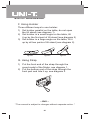
1
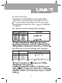
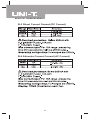
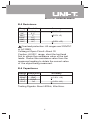
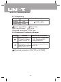
Model UT57: OPERATING MANUAL
Table of Contents
A.
B.
C.
D.
E.
F.
G.
Your Meter’s Feature
Specifications
Making Measurements
Maintenance
Accessories
Using Holster
Using Strap
Introduction
UT57 is one type of UNI-T brand new UT50 series
Multimeters with 4 1/2 digits, which has special
and steady function and is a highly reliable hand
-held measuring instrument. The design of the
Meter is the use of CMOS technology with large
scale of integrated circuit using double integrated
A/D tranducer as its core and has full ranges overload
protection.The Meter can measure DC current,
AC current, DC Voltage, AC Voltage, Resistance,
Capacitance, Diode, Frequency and Continuity
Beeper. AC Voltage and Current measurement
is TRMS and has the function of AC+DC/AC which
is an ideal tool for users.
1
Model UT57: OPERATING MANUAL
Safety Rules
l Use the Meter only as specified in this
manual, otherwise the protection provided
by the Meter may be impaired.
l The meter is designed to withstand the
stated Max. voltages. If it is not possible
to exclude without doubts that impulses,
transients,disturbance or for other reasons,
these voltages are exceeded a suitable
prescale (10:1) must be used.
l Do not operate the Meter before the cabinet
has been closed and screwed safely as
terminal can carry voltage.
l Make sure the Meter is set to the suitable
range before each measurement.
l Before using the Meter, please inspect the
case and test leads for damaged insulation
or exposed metal.
l Connect the red and black test lead to the
correct measuring input jack properly.
l Do not input values over the maximum
range of each measurement to avoid
damages of the Meter.
l Do not turn the rotary function switch
during Voltage or Current measurement,
otherwise the Meter could be destroyed
2
Model UT57: OPERATING MANUAL
l
l
l
l
l
l
l
l
l
Make sure to use new fuses with proper
rating to instead of bad fuses.
To avoid electric shock or damages, do not
apply more than 1000V between the “COM”
terminals and “ ”earth ground.
Use caution when working with Voltages
above 60V (DC) or 30Vrms (AC). These
Voltages pose shock hazard.
Replace the battery as soon as the battery
indicator “ ”appears. With a low battery,
the Meter might produce false readings
that can lead to electric shock and personal
injury.
Turn off the Meter once finished measuring.
Do not operate the Meter under adverse
environmental condition including high
temperature and especially humid area as
the Meter's function may be effected after
moisturizing.
To avoid damages and dangers, do not
change the circuit.
Periodically wipe the cabinet with a damp
cloth and mid detergent. Do not use
abrasives or solvents.
International Electrical Symbols:
Low Battery
Earth Ground
Warning
Double Insulated
AC
Diode
Buzzer
DC
Fuse
Dangerous Voltages
3
Model UT57: OPERATING MANUAL
A. Your Meter’s Feature
l 21 ranges.
l Liquid Crystal Display, digit’s height is
21mm .
l Overload display “l”.
l Maximum display “19999”.
l Full range symbol display.
l Full range overload protection.
l Auto-Power Off.
l Operating Temperature:
o
o
o
o
0 C to 40 C (32 F to 104 F ) .
l Storing Temperature:
o
o
o
o
-10 C to 50 C (14 F to 122 F) .
l Altitude:Operation:2000m.
Storage:10000m.
l Relative humidity:Max.relative humidity 80%
o
for temperature up to 31 C decreasing.
o
linearly to 50% relative humidity at 40 C.
l Low Battery display“ ”
l Battery type:9V Zinc,NEDA1604 or 6F22
or 006P.
l Fuse:F.0.3A/250Vφ5x20mm.
F.10A/250Vφ6x25mm.
l Measuring Dangerous Voltage display“ ”
l Strap for easy carry.
l Dimension: 190 x 88 x 34mm.
l Weight: about 270gram (excluding test
leads).
4
Model UT57: OPERATING MANUAL
B. Specifications
Accuracy is specified for one year after
calibration,at operating temeratures 23oC
5oC,with relative humidity at<75%.Accuracy
specifications take the form of: (a% readings
+n digits)
B-1 Direct Current Voltage (DC Voltage)
B-2 Alternate Current Voltage (AC Voltage)
Accuracy
Range Resolution
200mV
2V
20V
200V
750V
10µV
100µV
(0.8% +20)
1mV
10mV
100mV
(1.0% +50)
5
Model UT57: OPERATING MANUAL
B-3 Direct Current Current (DC Current)
B-4 Alternate Current Current (AC Current)
6
Model UT57: OPERATING MANUAL
B-5 Resistance
Range Resolution
200Ω
2KΩ
20KΩ
200KΩ
2MΩ
20MΩ
Accuracy
0.01Ω
0.1Ω
1Ω
10Ω
100Ω
1KΩ
(0.1% +5)
(0.1% +2)
(0.3% +10)
Overload protection: All ranges are 230VDC
or AC RMS.
Voltaeg at Open Circuit: About 3V
Caution: At 200Ω range, short the test lead
first to obtain the resistance value of the test
leads. Deduct the resistance value from the
measured reading to obtain the correct value
of the object being measured .
B-6 Capacitance
Range Resolution
1pF
20nF
10pF
200nF
0.1nF
2µF
1nf
20µF
Accuracy
(2.0% +10)
(2.5% +30)
Testing Signals: About 400Hz, 40mVrms.
7
Model UT57: OPERATING MANUAL
2-7 Frequency
Range
Resolution
20kHz
1Hz
200kHz
10Hz
Accuracy
(1.0% +20)
Input sensitivity: 200mV rms,
Max Input Scope: 30V rms.
Overload protection: 230V rms
2-8 Diode and Continuity Beeper
Range
Remark
Measuring Condition
Forward DC Current abt
1mA, Backward DC
Voltage abt2.8V
Display Diode
Forward Voltage
Value, unit is "V"
Beeper sounds when
Resistance < 30Ω. Voltage at open Circuit
Display the nearest abt 3.0V
value, unit is "kΩ"
Overload protection: 230V DC or AC RMS.
8
Model UT57: OPERATING MANUAL
C. Making Measurements
Caution
(1) If there is no display or “ ” is shown on the
LCD when the Meter is switched on, replace
the battery ASAP.
(2) Never exceed the maximum input voltage or
current limits shown besides the input jacks
“ ” , otherwise the Meter's internal circuit will
be damaged and this is dangerous to life.
(3) Become familiar with all buttons,and Turn the
rotary switch to proper range before operating.
(4) Put the / On/Off button at “ ” position as
do not measure AC current or voltage,otherwise,
The LCD will appear “ AC ” symbol.
1. LCD Display
2.
+ / On/Off Button
3.
/ On/Off Button
4. Rotary Switch
5. COM Input Jack
6. Capacitance Jack
7. Power On/Off Button
8. Data-Hold Button
9. 200mA~10A lnput Jack
10. Below 200mA Input Jack
11.
V Ω Hz lnput Jack
9
Model UT57: OPERATING MANUAL
C-1 Measuring DC Voltage
1)
/ Button should not be pressed down
and LCD should not display “AC” Symbol.
2) Connect the black test lead to “COM” jack and
red test lead to “ V ” jack.
3) Set the rotary switch to “ V ”
4) Connect the test leads across with the object
to be measured. LCD appears the measuring
value and also the polarity of the red test leads.
Caution
1) If magnitude of the voltage is unknown, always
start with the highest range and reduce until
satisfactory reading is obtained.
2) If “1” is shown on the LCD, it means the Meter
is overloaded, then set the measuring range
to higher.
3) “ ” means never exceed the maximum input
limits, 1000V, otherwise internal circuit of the
Meter will be damaged even though it is still
possible to display higher voltage value.
4) Take extra care of voltage leakage when
measuring high voltage.
C-2 Measuring AC Voltage
1) Press down
/ button to display "AC" on
LCD. If + / button is not pressed, it
means the measuring value is the sum of
Direct and Alternate Current ( + ). While
if + / button is pressed, it means the
measuring value is a pure Alternate Current
TRMS.
10
Model UT57: OPERATING MANUAL
2) Connect the black test lead to “COM” jack and
red test lead to “V” jack.
3) Set the rotary switch to “V ”
4) Connect the test leads across with the object
to be measured.
Caution
1) Refer to “DC Voltage Caution” 1, 2, 4
2) “ ” means never exceed the maximum input
limits, 750V, otherwise internal circuit of the
Meter will be damaged even thought it is still
possible to display higher voltage value.
3) The input value should be 10% more than the
selected ranges to fulfill accuracy requirement.
C-3 Measuring DC Current
1) Press / button down not to display "AC"
on the LCD
2) Connect the black test lead to “COM” jack.
When measuring 200mA or below, connect
the red test lead to “mA” jack. When measuring
10A or below, connect the red test lead to "10A"
jack.
3) Set the rotary switch to “A ”
4) Connect the test leads in series with the object
to be measured, the LCD display the measuring
value and polarity of red test lead.
Caution
1) If magnitude of the current is unknown, always
start with the highest range and reduce until
satisfactory reading is obtained.
11
Model UT57: OPERATING MANUAL
2) If “1” is shown on the LCD, it means the Meter
is overloaded, then set the measuring range
to higher.
3) “ ” means the maximum input current is 200mA,
overload will cause the burn of fuse. 10A range
has 10A/250V fuse protection
C-4 Measuring AC Current
1) Press down / button to display “AC “on
LCD. If + /
button has not been
pressed down, it means the measuring value
is the sum of Direct and Alternate Current (
+ ). While + / has been pressed
down, it means the measuring value is a pure
alternate current effective value.(TRMS)
2) Connect the black test lead to “COM” jack.
When measuring 200mA or below, connect
the red test lead to “mA” jack. When measuring
10A or below, connect the red test lead to
“10A” jack.
3) Set the rotary switch to “A ”
4) Connect the test leads in series with the object
to be measured.
Caution
1) Please refer to “DC Current Caution” 1, 2, 3.
2) The input value should be 10% more
than the selected ranges to fulfill the accuracy
requirement.
12
Model UT57: OPERATING MANUAL
C-5 Measuring Resistance
1) Connect the black test lead to “COM” jack
and red test lead “Ω”jack.
2) Set rotary switch to “Ω”
3) Connect the test leads across with the object
to be measured.
Caution
1) If “1” is shown on the LCD, which means the
Meter is overloaded, then set a higher measuring
range. If resistance is above 1MΩ, the reading
will only be steady in few seconds which is
normal for measuring higher value of resistance
2) “1” is displayed when open circuit or no input.
3) Make sure all objects, circuit and components
to be measured are without voltage and
discharge all high-voltage capacitors.
C-6 Measuring Capacitance
1) Input the being measured capacitor to the
capacitance jack (not require test lead)
2) Before measuring capacitance, remember it
takes time for zeroing when changing ranges.
Floating reading does not effect accuracy.
Caution
1) To avoid damage of the Meter or the equipment
under test, disconnect circuit powers and
discharge all high-voltage capacitors before
measuring capacitance.
2) Input capacitor to the capacitance jack.
3) Stabilizing reading takes time when measuring
high capacitance
4) Unit: 1pF=10-6 µF, 1nF = 10-3 µF
13
Model UT57: OPERATING MANUAL
C-7 Measuring Frequency
1) Connect red test lead to “Hz” jack and black
test lead to “COM” jack.
2) Set the rotary switch to “kHz”
3) Connect the test leads across with the object
being measured. LCD appears the frequency
value.
Caution
When measuring above 30Vrms, accuracy could
not be guaranteed and take extra care of safety
as voltage brings dangerous electricity .
C-8 Measuring Diode and Continuity beeper
1) Connect the black test lead to “COM” jack
and red test lead to “VΩ ” jack (Red test lead
polarity is "+")
2) Set the rotary switch to “
”
3) Connect the test lead across with the object
being measured.The reading is Diode Forward
Voltage Drop Nearest Value.
4) Connect the test lead to object’s two points
being measured, the beeper sounds if the
resistant value between the two points is
below 30Ω.
C-9 DATA-Hold
1) Press DATA-H to enter and exit the hold mode
2) It is not necessarily to connect the test lead.
14
Model UT57: OPERATING MANUAL
C-10 Auto-Power Off function
1) The Meter equips with auto-power off function.
It will be in a sleep mode when it has been
oprated for 30 minutes. Power will be
automatically cut off.
2) Press the on/off switch two times to power up
again.
D Maintenance
The Meter is a highly precise electrical testing
instrument, do not attempt to change the circuit
of your Meter . Take a note of the following few
points:
1) Do not connect to DC Voltage above 1000V
or AC Effective Value Voltage above 750V
2) Do not input voltage when the rotary switch
is in “Current Range”, “Ω”,, “
”
3) Do not operate the Meter if battery is not inside
the Meter or bottom cabinet is not securely
screwed.
4) Disconnect the test leads and power off the
Meter before replacing the Battery and Fuses.
E. Accessories
1) A book of users manual
2) A pair of test lead
3) A piece of holster (if selected)
15
Model UT57: OPERATING MANUAL
F. Using Holster
Three different ways to use holster:
1) Set holster parallel on the table, do not open
the tilt stand (see diagram 1)
2) Set holster in a small angle on the table, tilt
it up by the first part of tilt stand (see diagram 2)
3) Set holster in a large angle on the table, tilt it
up by all two parts of tilt stand (see diagram 2).
figure1
figure2
figure3
G. Using Strap
1) Put the front end of the strap through the
round metal of the Meter, see diagram 1.
2) Put the bottom end of the strap through the
front part and tide it up, see diagram 2.
~ END ~
* The manual is subject to changes without separate notice. *
16
Model UT57: OPERATING MANUAL
Manufacturer: UNI-TREND TECHNOLOGY(DONG GUAN)LIMITED
Address: Dong Fang Da Dao, Bei Shan Dong Fang Industrial
Development District, Hu Men Town, Dong Guan City,
Guang Dong Province, China
Headquarters: Uni-Trend International Limited
Address: Rm901, 9/F, Nanyang Plaza 57 Hung To Road
Kwun Tong Kowloon, Hong Kong
Tel: (852) 2950 9168
Fax: (852) 2950 9303
Email: [email protected]
http://www.uni-trend.com
17