1
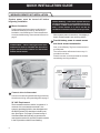
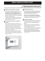
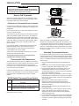
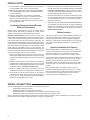
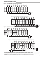
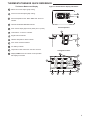
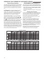
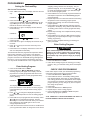
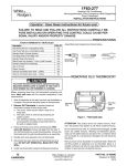
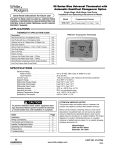
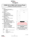
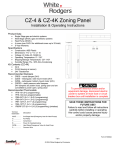
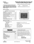
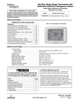
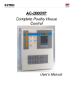
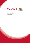
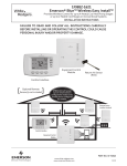
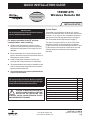
QUICK INSTALLATION GUIDE
Read Installer Notes
before removing cover
from Thermostat.
1F85RF-275
Wireless Remote Kit
INSTALLER NOTES
System Power
IMPORTANT
Do not apply power to the thermostat or wireless
sensor until instructed to do so.
For proper operation of the RF wireless
communication, when installing:
z
Avoid locating thermostat or sensor near any
wireless or noise generating devices, particularly
radio devices that operate in the range of 418 to
428 MHz.
z
Be sure that there are no electrical wires, metal
pipes or ductwork in the part of the wall chosen for
thermostat or sensor location
z
Avoid locating the thermostat or sensor on a
concrete wall, metal junction box or metal plate.
z
Thermostat antenna wire must be installed into the
wall. Do not allow the antenna wire to be between
the thermostat and the wall.
z
Thermostat must have uninterrupted 24VAC for
proper communication.
Any of the above can diminish or prevent proper
RF communication for this kit. Be sure to perform
a thorough checkout and confirm signal strength
between thermostat and wireless sensor.
FAILURE TO READ AND FOLLOW ALL
INSTRUCTIONS CAREFULLY BEFORE
INSTALLING OR OPERATING THIS
CONTROL COULD CAUSE PERSONAL INJURY
AND/OR PROPERTY DAMAGE.
!
Thermostat is received from the factory for system
power to be hardwired with a common wire connected to
terminal C. If no common wire is available, the thermostat will use Power Stealing and must be configured.
See Thermostat 24VAC Requirement on page 5.
This device complies with Part 15 of the FCC Rules.
Operation is subject to the following two conditions:
(1) this device may not cause harmful interference, and
(2) this device must accept any interference received,
including interference that may cause undesired
operation.
Index
Wireless Remote Kit Installation
Applications
Specifications
Installation
Wiring Connections
Thermostat/Sensor Quick Reference
Installer Configuration Menu
Operating Your Thermostat and Sensor
Programming
Troubleshooting
Page
2
4
4
5
6
8
10
14
17
18
PART NO. 37-6841E
www.white-rodgers.com
www.emersonclimate.com
Replaces 37-6841C and D
1039
1
QUICK INSTALLATION GUIDE
WIRELESS REMOTE KIT INSTALLATION
System power must be turned off before
beginning installation
1
Power Stealing – If the HVAC system does not
provide enough power, we recommend connecting
a 150 Ohm, 10 Watt resistor between terminals W
and C of the furnace or Y and C on the air
conditioner or both to increase the power provided.
Mount thermostat
Position and mount thermostat on wall following
standard installation procedures. Questions on
installation, see Guidelines for Thermostat/Sensor
Locations and Mounting Thermostat and Sensor on
page 5.
When system power is turned on, if the display is
blank, the thermostat is not receiving 24VAC.
3
Antenna Wire – When installing the thermostat,
antenna wire must be installed into the wall for
proper communication between the thermostat
and the remote sensor.
Provide battery power to remote sensor
and check sensor transmission
Now, remove Battery Tag from remote sensor to
provide power.
The remote sensor will transmit once every 10
seconds for one hour.
Place the sensor on the thermostat for the best
transmitting-receiving conditions.
Thermostat Antenna Wire
installed through wall
Indicates
sensor is
transmitting
signal
Indicates
sensor is
receiving
signal
Signal
strength
2
Connect wires to thermostat
Connect wires following standard wiring procedures.
Questions on wiring, see system diagrams on page 7.
24 VAC Requirement
The thermostat must have 24VAC to operate. If a
common wire is connected to terminal C, the
system is providing 24VAC to the thermostat and
the RC/PS switch (S7) should be in the RC position. (See Figure 1 on page 5) Proceed to step 3.
If the thermostat does not have a common wire
connected to terminal C, the RC/PS switch must be
in the PS position to allow Power Stealing.
2
QUICK INSTALLATION GUIDE
WIRELESS REMOTE KIT INSTALLATION
4
Confirm that thermostat is receiving
6
Once the ideal position is determined, mark mounting holes for the remote sensor. The batteries will
have to be removed from the remote sensor to
access the mounting hole under them.
The thermostat receiving icon and the sensor
transmitting icon will appear at the same time. The
thermostat display will show SIGNAL and the
strength of the signal, 3 bars high signal strength, 2
bars medium signal strength, and 1 bar low signal
strength. The display will also show the temperature
sensed by the remote sensor.
During the one hour after remote sensor power-up,
the thermostat should be receiving signals consistently (6 signals in one minute).
5
Position Remote Sensor at installation
location
Once communication has been confirmed, move
remote sensor to permanent location. Do not mount
remote sensor or drill holes to mount sensor yet.
Have someone hold the remote sensor at the
desired mounting location. Hold remote sensor on
the left side to avoid interference with the transmitting antenna on the right side.
Return to the thermostat and confirm that good
communication with the thermostat can be established as described in step 5. Ideal consistency is 6
signals in 1 minute.
Mount Remote Sensor
After mounting the remote sensor, reinstall the
batteries. The remote transmitter will begin transmitting again. Confirm that communication with the
thermostat is still good as describe in step 5.
7
Complete Installation
Perform operation check of thermostat with heating
and cooling systems. Questions on thermostat
operation, see Check Thermostat Operation on
page 13.
Check Remote Sensor operation as described in
Remote Temperature Sensor Information on the
Thermostat Display on page 14.
In normal operation, the remote sensor will transmit
when it senses a temperature change of 3/16 of a
degree from the last transmission or after 10
minutes. The antenna icons will turn on briefly to
indicate the sensor is transmitting and the thermostat is receiving.
3
Save these instructions
for future use!
FAILURE TO READ AND FOLLOW ALL INSTRUCTIONS
CAREFULLY BEFORE INSTALLING OR OPERATING THIS
CONTROL COULD CAUSE PERSONAL INJURY AND/OR
PROPERTY DAMAGE.
1F85RF-275 Thermostat and
Wireless Remote Sensor Kit
Automatic Heat/Cool Changeover Thermostat for Single Stage/
Multi-Stage/Heat Pump Systems with Wireless Remote Sensor
Installation and Operating Instructions for Model:
Model
Programming Choices
1F85RF-270
5/1/1 Day
F145RF-1328
Non-Programmable
Wireless Remote Sensor
APPLICATIONS
THERMOSTAT APPLICATION GUIDE
Description
Heat Pump (No Auxiliary or Emergency Heat)
Heat Pump (with Auxiliary or Emergency Heat)
Standard Heat & Cooling Systems
Multi-Stage Systems requiring more than
One Call for Heat or Cool
Standard Heat Only Systems
Millivolt Heat Only Systems – Floor or Wall Furnaces
Standard Central Air Conditioning
Gas or Oil Heat
Electric Furnace
Hydronic (Hot Water) Zone Heat – 2 Wires
Hydronic (Hot Water) Zone Heat – 3 Wires
Yes
Yes
Yes
Yes
Yes
No
Yes
Yes
Yes
* Yes
No
1F85RF-270
Thermostat
F145RF-1328 Wireless
Remote Sensor
* Common Connection Required
SPECIFICATIONS
Thermostat:
Remote Sensor:
Electrical Ratings .......................... 20 to 30 VAC 50/60 Hz
0.2 to 0.6 Amps per Load
(Y1, E/W1, G)
1.5 Amps (Y2, W2, O, B
Load per terminal)
1.5 Amps Max
(All terminals combined)
Setpoint Range .............................. 45 to 90°F (7 to 32°C)
Rated Differential (Single Stage) ... Heat 0.6° or 1.5°F, Cool 1.2°F
Rated Differential (Multi-Stage) ..... Heat 0.6° or 1.5°F, Cool 1.2°F
Rated Differential (Heat Pump) ..... Heat & Cool 0.75° or 1.2°F
Operating Ambient ........................ 32 to +105°F (0 to +41°C)
Operating Humidity ....................... 90% non-condensing max.
Shipping Temp. Range .................. -4 to +150°F (-20 to +65°C)
Thermostat Dimensions ............... 3-3/4"H x 6"W x 1-1/4"D
This device complies with Part 15 of the FCC Rules, Operation is
subject to the following two conditions: (1) this device may not
cause harmful interference, and (2) this device must accept any
interference received, including interference that may cause
undesired operation.
Maximum Wireless Remote Sensors .... 1 indoor, 1 outdoor
Operating Range .................................... 45 to 90°F (7 to 32°C)
Operating Humidity Range ..................... 0 to 90% RH
(non-condensing)
Dimensions ............................................. 2-5/8"H x 4-1/4"W x 7/8"D
* Max. Distance from Thermostat .......... 200 feet
!
* Distance shown is for a typical application. Distances may vary in
some applications because obstacles that block the signal path
may affect the strength of the signal.
ATTENTION: MERCURY NOTICE
This product does not contain mercury. However, this product may replace a product which contains mercury.
WARNING
Thermostat installation and all components of the
control system shall conform to Class II circuits per the
NEC code.
Mercury and products containing mercury must not be discarded in household trash. Do not touch any spilled mercury.
Wearing non-absorbent gloves, clean up any spilled mercury
and place in a sealed container. For proper disposal of a
product containing mercury or a sealed container of spilled
mercury, place it in a suitable shipping container. Refer to
www.white-rodgers.com for location to send product containing mercury.
PART NO. 37-6841E
www.white-rodgers.com
Replaces 37-6841C and D
1039
INSTALLATION
ELEC/GAS SWITCH
! CAUTION
To prevent electrical shock and/or equipment damage,
disconnect electric power to system at main fuse or
circuit breaker box until power is required.
Remove Old Thermostat
Before disconnecting wires from the old thermostat, mark
wires for terminal identification so the proper wiring connections will be made to the new thermostat.
RC/PS
SWITCH
ANTENNA
WIRE
MOUNTING
HOLE
MOUNTING
HOLE
Figure 1 – Thermostat base
ANTENNA
WIRE
REMOTE
COMMUNICATION
RECEIVER
Guidelines for Thermostat/Sensor Locations
Locate the thermostat/sensor about 5 ft. above floor level on
an interior wall in an area that represents the average room
temperature.
Figure 2 – Back of thermostat base
MOUNTING HOLE
Do not mount directly on or near HVAC equipment or other
sources of electrical noise.
Avoid locations close to windows or near adjoining outside
walls, doors leading outside, areas close to air registers or
their direct air flow or areas with poor circulation like alcoves.
Avoid locating the sensor on a concrete wall, junction box or
metal plate. Make sure there are no electrical wires, metal,
pipes or duct work in the part of the wall chosen for the
sensor location.
For proper RF wireless communication, the antenna wire
MUST be installed into the wall. If the antenna wire is
hanging between the wall and the thermostat the RF
communication may not be reliable
Antenna wire must be installed into the wall, it can not be
between the thermostat and wall.
Thermostat and indoor sensor are not approved for
installation in unconditioned space.
Thermostat 24 VAC Requirement
The thermostat must have 24 VAC supplied for the receiver
to operate. When the system wiring is connected, if a system
common wire is connected to terminal C, the system is
providing 24 VAC to the thermostat. The RC/PS switch (see
Fig 1) must be in the RC position.
If the thermostat does not have a common wire connected to
terminal C, the thermostat can use Power Stealing to get the
required 24 VAC. The RC/PS switch must be in the PS
position.
RC/PS Switch (Thermostat Power Option)
RC/PS
Switch
Position
Description
RC
For Hardwire Applications. Requires Common Wire
from System Transformer to "C" Terminal on Thermostat
PS
For Power Stealing Applications. Use When Common
from the System Transformer is not Available for
Connection to the "C" Terminal on the Thermostat
NOTE: If set to PS (Power Stealing), the thermostat "C" terminal
must not have a wire connected.
ANTENNA
MOUNTING HOLE
Figure 3 – Remote sensor base
When the system is not providing enough power for the
thermostat, the display will be bright when the system is not
running and dim when the system is running. If the system is
not providing enough power, we recommend connecting a
150 Ohm, 10 Watt resistor between terminals W and C of the
furnace or Y and C of the air conditioner, or both, to increase
the power provided.
Mounting Thermostat and Sensor
Do not remove battery tag to power the sensor with batteries
until instructed to do so. The thermostat requires 24 volt system
power to operate correctly. If the thermostat goes blank, system
power is not reliable and will be corrected in the System Power
section below.
1. Remove the packing material from the thermostat and
sensor.
2. Pull the front cover of the thermostat straight off the base.
Forcing or prying will cause damage to the control.
3. Using the thermostat base as a template, place on the
selected wall locations and mark the location of all
mounting holes (Figure 1), and the hole for the thermostat
antenna wire illustrated in Figure 2.
4. Move base out of the way and drill the holes. If mounting
holes drilled are too large and do not allow you to tighten
base snugly, use the plastic screw anchors (provided) for
secure mounting.
5. Make sure the remote communication receiver is
plugged in properly to the thermostat and that the
antenna wire is routed through the thermostat subbase
as shown in Figure 2.
6. Insert antenna wire into the wall and position base into
mounting position.
7. Fasten base loosely to wall, using two mounting screws.
Place a level against bottom of base (leveling is for
appearance only and will not affect sensor operation)
and then tighten screws.
8. In the thermostat location, push excess wire into wall and
plug hole with a fire resistant material (such as fiberglass
insulation) to prevent drafts from affecting the thermostat
operation.
5
INSTALLATION
9. Connect wires to thermostat terminals as required. Refer
to wiring diagrams Fig. 4 thru 7 for proper wiring.
10.Apply system power and confirm that thermostat display
is on and SYSTEM mode is OFF. Press SYSTEM button
to OFF if necessary.
11.Enter the configuration as described in Thermostat
Configuration Menu on page 10. Configure the thermostat for system operation. While in the configuration
menu, enable the indoor remote wireless sensor (item 4)
by changing OFF to ON.
Confirming Communication of Remote
Sensor to Thermostat
Before finding a good location to mount the remote sensor,
confirm that the thermostat is receiving the remote sensor
signals consistently and at the best strength possible.
Reliable Communication: While the sensor is in the Learn
Mode, to be sure the thermostat and sensor have good communication. The thermostat receiving icon and the sensor transmitting icon will appear and turn off at about the same time. The
thermostat will display SIGNAL and the strength of the signal.
3 bars indicates a strong signal and the most desirable, 2 bars
indicates a medium strength signal and 1 bar indicates a weak
signal which is acceptable if it can not be improved. The
thermostat display will also show the temperature sensed by the
remote. The thermostat should receive 6 signals in 1 minute and
the signal strength should be 3 bars if possible.
1. Remove the battery tag from only the remote sensor. The
battery tag must still be in the thermostat. The remote sensor
will begin transmitting a signal once every 10 seconds for
one hour.
2. Place the remote sensor on the thermostat and check that
the thermostat is receiving signals from the sensor. Confirm
that the sensor and thermostat have reliable communication
as described above in Reliable Communication.
3. Move the remote sensor to the room where it is to be
installed. Do not mark a mounting location or drill holes yet.
4. Have someone hold the remote sensor at the location
selected for the remote sensor. Hold the remote sensor on
the left side to avoid interference with the transmitting
antenna on the right side of the sensor.
6. Return to the sensor and confirm that reliable communication with the sensor can be established again as described
in Reliable Communication. Have the sensor moved, if
necessary to improve the signal strength if it is not a consistent signal with signal strength of 3 bars.
7. Once the ideal position for the sensor is determined, mark
mounting holes using the sensor base as a template (Figure
3). The batteries will have to be removed to access a
mounting under them.
8. After the sensor is firmly attached to the wall and the batteries
are reinstalled, the remote sensor will begin transmitting
again for one hour. Return to the thermostat and once again
confirm that communication is still good as described in
Reliable Communication.
Battery Location
The sensor requires 2 "AAA" alkaline batteries. Batteries are
included at the factory with a battery tag to prevent power
drainage. The battery tag must be removed to engage the
batteries. For best results, replace batteries once a year with
new premium brand alkaline batteries such as Duracell® or
Energizer®.
Electric/Gas Switch (Fan Option)
The ELEC/GAS switch on the thermostat (Fig. 1) is factory
set to the ELEC position. In this position, the thermostat will
power the circulator fan on a call for heat. Electric heat
systems may require the switch to be in the ELEC position.
If your system does not require that the thermostat power the
circulator fan, this switch should be set to the GAS position.
Typically, gas and oil heating systems do not require the
thermostat to power the circulator fan during a call for heat. If
your heat is gas or oil, the switch should be set to the GAS
position.
When the thermostat is configured for Heat Pump, the
thermostat will always power the circulator fan on a call for
heat in the HEAT mode. The ELEC/GAS switch must be set
to match the type of Auxiliary heat your system uses for
proper operation in the EMERgency mode.
WIRING CONNECTIONS
Typical wiring diagrams are provided below for the following systems:
Single Stage Heat/Cool systems
Multi-Stage Heat/Cool systems (No Heat Pump)
Heat Pump system, one compressor or one speed compressor with Aux. Heat
Heat Pump systems, two compressors or two speed compressor with Aux. Heat
Refer to the equipment manufacturers instructions for specific wiring information. After completing the connections configure
the thermostat in the Installer Configuration Menu to match your system type.
6
WIRING CONNECTIONS
Figure 4 – Single Stage (No Heat Pump) Terminal Outputs
R
*C
Y1
W2
Y2
O
B
L
Energized
in Cool
Mode
(Changeover Valve
or Damper)
Energized
in Heat, Off
Mode
(Changeover Valve
or Damper)
Fault
Indicator
for Heat
Pump
Systems
with
Malfunction
Switch
G
E/W1
System
Single Stage
(SS1)
24 Volt
(Hot)
Blower/
Circulator
Fan Energized
on Call for
Cool or Fan,
Energized on
Call for Heat if
Elect/Gas
Switch Set to
Electric
24 Volt
Heat
(Common) Cool Mode
No Output No Output Mode
1st Stage
Optional
1st Stage
Connection (Compressor)
(Heater)
NEUTRAL
120VAC
24VAC
HOT
CLASS II
TRANSFORMER
Figure 5 – Multi-Stage (No Heat Pump) Terminal Outputs
R
Y1
*C
W2
Y2
G
E/W1
O
B
L
Energized
in Cool
Mode
(Changeover Valve
or Damper)
Energized
in Heat, Off
Mode
(Changeover Valve
or Damper)
Fault
Indicator
for Heat
Pump
Systems
with
Malfunction
Switch
System
Multi-Stage
(MS2)
24 Volt
24 Volt (Common) Cool Mode
Heat
Cool Mode Heat
(Hot)
Mode
2nd Stage Mode
1st Stage
Optional
Connection (Compressor 1) (Compressor 2) 2nd Stage 1st Stage
Blower/
Circulator
Fan Energized
on Call for
Cool or Fan,
Energized on
Call for Heat if
Elect/Gas
Switch Set to
Electric
NEUTRAL
120VAC
24VAC
HOT
Figure 6 – Heat Pump Terminal Outputs
R
*C
W2
Y2
Y1
CLASS II
TRANSFORMER
O
B
L
Energized
in Cool
Mode
(Changeover Valve)
Energized
in Heat, Off,
Emergency
Mode
(Changeover Valve)
Fault
Indicator
for Heat
Pump
Systems
with
Malfunction
Switch
G
E/W1
System
Heat
Mode
2nd Stage.
24 Volt
Emergency
24 Volt (Common) Heat ModeMode 2nd
Stage
Emergency
(Hot)
1st Stage
Optional
Mode
Connection Cool Mode- Heat Mode- Heat
Heat Pump 2
1st Stage
Mode
1st
Stage
(HP2)
2nd Stage
3rd
Stage.
(Compressor
1)
Two
Cool Mode- Emergency
Compressor
2nd Stage Mode 2nd
or Two Speed
(Compressor
2) Stage
Compressor
Heat Pump 1
(HP1)
Single
Compressor
Heat Pump
No Output
Blower/
Circulator
Fan Energized
on Call for
Heat/Cool
or Fan,
Note: Set
Elect/Gas
switch for
Emergency
Mode Heat Type
NEUTRAL
120VAC
24VAC
HOT
CLASS II
TRANSFORMER
Figure 7 – Heat Pump Terminal Outputs - Two Transformer with no Safety Circuits
R
*C
Y1
Y2
W2
E/W1
G
O
B
L
Energized
in Cool
Mode
(Changeover Valve)
Energized
in Heat, Off,
Emergency
Mode
(Changeover Valve)
Fault
Indicator
for Heat
Pump
Systems
with
Malfunction
Switch
System
Heat
Blower/
Mode
Circulator
2nd Stage.
Fan Energized
24 Volt
Emergency
on Call for
24 Volt (Common) Heat ModeMode 2nd
Heat/Cool
Stage
Emergency
(Hot)
1st Stage
Optional
or Fan,
Mode
Connection Cool Mode- Heat Mode- Heat
Heat Pump 2
1st Stage
Note: Set
1st Stage
(HP2)
2nd Stage Mode
3rd Stage.
Elect/Gas
(Compressor 1)
Two
Cool Mode- Emergency
switch for
Compressor
2nd
Stage
Mode
2nd
Emergency
or Two Speed
(Compressor 2) Stage
Mode Heat Type
Compressor
Heat Pump 1
(HP1)
Single
Compressor
Heat Pump
No Output
HEAT
COOL
NEUTRAL
120VAC
24VAC
120VAC
NEUTRAL
24VAC
HOT
HOT
CUT AND
TAPE OFF
TWO COMMONS MUST
BE JUMPERED TOGETHER
CLASS II
TRANSFORMER
* The RC/PS switch shown in Figure 1 configures the thermostat for Hardwire or Power Stealing.
The factory setting is RC (Hardwire) and requires a Common connection from the system transformer to the "C" terminal on
the thermostat. If no common wire is available for the thermostat "C" terminal, move the RC/PS switch to PS (Power Stealing). NOTE: If set to PS (Power Stealing), the thermostat "C" terminal must not have a wire connected.
7
THERMOSTAT/REMOTE SENSOR QUICK REFERENCE
Before operating the thermostat, familiarize yourself with the
display and button functions. Both thermostat and remote
sensor consist of two parts: the cover and the base. To remove
a cover, pull it straight out from the base. To replace a cover, line
it up with the base and press until the cover snaps into place on
the base.
2
The Thermostat Buttons and Switches and Display
1
Raises and lowers the temperature setting.
2
Light flashes every 20 seconds indicating acceptable
signal reception from indoor or outdoor remote sensor.
3
Buttons for setting time (Time), programming (Prgm),
running program (Run) and bypassing program to
hold a constant temperature (Hold).
4
4
6
5
7
SYSTEM button (COOL, AUTO, HEAT, OFF, EMER
heat pump systems only).
8
5
FAN switch (ON, AUTO).
9
6
Displays the active temperature sensor (outside,
remote, local) and its sensed temperature if more than
one sensor is enabled.
10
7
Displays ( ) when in keypad lockout mode.
8
Indicates day of the week.
9
Indicates the thermostat mode information:
"HOLD" alternates with the system mode (see item 12)
if the HOLD button is pressed to bypass the program
and maintain a constant temperature.
10
Displays currently programmed set temperature (blank
when SYSTEM is OFF).
11
Alternately displays the current time and the temperature average of sensors (thermostat [local] and/or
indoor remote) turned on.
12
13
8
"HEAT" is displayed when set to heating,
"COOL" is displayed when set to cooling,
"AUTO" is displayed when set for automatic changeover between heating and cooling.
When "AUTO" is displayed, the currently active mode
(Heat or Cool) will also display.
"EMER" is displayed flashing (heat pump systems
only) when the thermostat is set to the Emergency
Mode. Emergency is used to bypass the heat pump
and use only the back-up heating system.
"FLTR" is displayed as a reminder to change or clean
the air filter after system has run for the programmed
filter time period.
Stage 1 & 2 indicator.
"STG 1" indicates when the first stage heat or cool is
energized. "STG + 2" indicates when the second stage
heat or cool is energized. "+2" blinking indicates
Auxiliary Heat stages are energized on Heat Pump
Systems.
12
11
14
13
15
16
17
Figure 8 – Thermostat display, buttons and switches
14
Displays "LR" when the limited range feature is
activated. Limited range limits the temperature the
thermostat can be set to.
15
Indicates the system is sending a fault signal to the
thermostat "L" terminal. This does not indicate a fault
in the thermostat.
16
Antenna will display for a few seconds when the remote
or outdoor transmitted signal is received.
17
Indicates the current signal strength level of the remote
temperature system. Signal strength level is low (one
bar on), medium (two bars on) or high (three bars on).
The remote will operate with 1 bar showing.
THERMOSTAT/SENSOR QUICK REFERENCE
The Sensor Buttons and Display
1
Raises the Comfort adjust graph setting.
2
Lowers the Comfort adjust graph setting.
3
Sensed temperature from –40 to 140°F with °F and °C
Figure 9 – Remote Sensor display and buttons
1
2
indicator
4
Channel identification A B C O indicator
5
9 bar comfort adjust graph with H (hotter) and C (cooler)
6
Transmission occurrence indicator
7
Keypad lockout indicator
8
Calibrate temperature offset indicator
9
Learn mode activated indicator
10
Low battery indicator
11
Temperature offset used when hold time is active
12
Displays PWR and on to indicate normal operation
with display turned OFF
Normal Operation
3
o
6
4
A
5
Configuration Items
3
5
o
6
H
7
LOCK
ABCO
CALIB
4
8
PWR HLD BATT LEARN C
5
5
12
11
10
9
9
THERMOSTAT CONFIGURATION MENU
INSTALLER/CONFIGURATION MENU
Press the System button until OFF is displayed, then press the
Press
or
to select
and
simultaneously
Step
Press
Button(s)
Displayed
(Factory Default)
1
System
MS2
SS1, HP2, HP1
Selects Single stage, Multi-stage, or Heat Pump
(Single stage or 2-stage) system configuration
2
System
LER (OFF)
LER (ON)
Selects learn mode OFF or ON
3
System
OUTSIDE (OFF)
OUTSIDE (ON)
Selects OUTSIDE sensor OFF or ON
4
System
REMOTE (ON)
REMOTE (OFF)
Selects REMOTE (indoor) sensor OFF or ON
5
System
LOCAL (ON)
LOCAL (OFF)
Selects LOCAL sensor ON or OFF
6
System
CH (0)
1 to 9
Select Receiver frequency offset
7
System
PRG 4
PRG 0, PRG 2
Selects Programmable Periods
8
System
EMR (ON)
EMR (OFF)
Selects Energy Management Recovery OFF or ON
9
System
CR HEAT COOL (FA)
SL
Selects Fast or Slow cycle selection
10
System
CL (OFF)
CL (ON)
Selects Compressor Lockout CL OFF or ON
11
System
CdL (ON)
CdL (OFF)
Selects Backlight Display ON or OFF
12
System
FA HEAT COOL (ON)
FA HEAT COOL (OFF)
Selects Fast Second Stage ON or OFF
13
System
0 FLTR
0–1950 (increments of 50)
Selects filter replacement run time.0 =Disabled
14
System
0F
(Room Temperature)
4 LO to 4 HI
Selects Temperature Display Adjustment 4 LO 4 HI
15
System
4:00 HOLD
0:00 to 8:00
(Increments of 15 minutes)
Selects Temporary Program Override Time
0:00 =Disabled
16
System
F
C
For C selection
Selects temperature display as F° or C°
17
System
LR HEAT (90)
LR 62 to LR 89
Selects Limited HEAT range
18
System
LR COOL (45)
LR 46 to LR 82
Selects Limited COOL range
19
System
CA (OFF)
CA (ON)
Selects Comfort Alert Lock
20
System
OFF LOCK
ON LOCK
Selects Button pad Lockout
0 00 LOCK
001 to 999
Selects Buttonpad lockout combination number
Press System to set code
21
Run
Returns to the OFF mode
The configuration menu allows you to set certain thermostat
operating characteristics to your system or personal requirements.
Set SYSTEM button to OFF, then simultaneously press
and
to enter configuration menu. The display will
show the first item in the configuration menu.
The configuration menu table summarizes the configuration
options. An explanation of each option follows.
Press SYSTEM to change to the next menu item. To exit the
menu and return to the program operation, press RUN. If no
keys are pressed within fifteen minutes, the thermostat will
revert to normal operation.
1) Single Stage, Multi-stage or Heat Pump Configuration
This menu item requires you configure the thermostat to
match your system. Choose your system option from the
table below:
System Type
Select Option
Single Stage Heat/Cool systems
SS1
Multi-Stage Heat/Cool systems (No Heat Pump)
MS2
Heat Pump system, 1 compressor or 1 speed compressor
HP1
Heat Pump systems, 2 compressors or 2 speed compressor
HP2
The thermostat is factory defaulted to MS2. To select a
different option, press the
or
key to scroll through
the choices.
10
Comments
2) Select Learn Mode On or Off – Selecting LER On
enables the learn mode of the thermostat receiver. Your
thermostat is configured at the factory to recognize the
remote sensor shipped with it. The Learn Mode Option
is used only when required as described in Learn Mode
Option.
3) Selects OUTSIDE sensor OFF or ON – Selecting
OUTSIDE ON enables the thermostat to read a wireless
outdoor temperature sensor that has been configured
for Sensor O in the Learn Mode. This allows the thermostat to display the outdoor temperature reading.
4) Selects REMOTE sensor OFF or ON – Selecting
REMOTE ON allows the thermostat to sense an indoor
remote sensor that has been set-up the Learn mode.
The maximum number of Indoor Remote Sensors is 1
configured to sensor A, B or C.
5) Selects LOCAL sensor ON or OFF – Appears if
Remote is set to ON. Selecting LOCAL ON allows the
thermostat to use the onboard temperature sensor
exclusively or for averaging with the remote sensor
readings. To control temperature using only the indoor
or
buttons
remote sensor temperature(s), use the
to select LOCAL OFF.
6) Select Receiver frequency offset – Appears if Remote is
set to ON. This option allows you to select a different
channel than the factory default for communication
between the thermostat and remote sensor. Note: If a
THERMOSTAT CONFIGURATION MENU
different channel is selected on the thermostat it must also
be changed to the same setting on the remote. This is
only used in areas where there are other wireless
devices or electronic equipment that interfere with the
default frequency of the thermostat/remote sensor
communication.
7) Programmable Periods – This control can be configured for 4, 2 or 0 programmable periods. The display
indicates "PRG 4" in the display as default. The programmable periods can be changed to 2 or 0 by pressing the
or
keys. With "PRG 0" selected for non-programmable, SYSTEM key selection will skip EMR (item 8) and
temporary program override (item 15).
8) Select Energy Management Recovery OFF or ON –
Energy Management Recovery (EMR) causes the
thermostat to start heating or cooling early to make the
building temperature reach the program setpoint at the
time you specify. Heating will start 5 minutes early for
every 1° of temperature required to reach setpoint.
Example: You select EMR and have your heating
programmed to 65° at night and 70° at 7 AM. If the
building temperature is 65° the difference between 65°
and 70° is 5°. Allowing 5 minutes per degree the thermostat setpoint will change to 70° at 6:35 AM. Cooling allows
more time per degree because it takes longer to reach
temperature.
9) Fast or Slow Cycle Selection – The factory default
setting is fast cycle, which cycles 1st stage at approximately 1.2°F and 2nd stage 0.75°F. If you prefer slow
cycle, press the temperature key to change to SL. The 1st
stage and 2nd stage would be 1.5°F and 1.2°F respectively.
10)Select Compressor Lockout CL OFF or ON – Selecting
CL ON will cause the thermostat to wait 5 minutes before
turning on the compressor if the heating and cooling
system loses power. It will also wait 5 minutes minimum
between cooling and heating cycles. This is intended to
help protect the compressor from short cycling. Some
newer compressors already have a time delay built in and
do not require this feature. Your compressor manufacturer can tell you if the lockout feature is already present
in their system. When the thermostat compressor time
delay occurs it will flash the setpoint for about five
minutes.
11)Select Backlight Display – The display backlight improves
display contrast in low lighting conditions. When the "C"
terminal is powered, selecting backlight CdL ON will keep
the light on continuously. Select backlight OFF will keep
the light on momentarily after any key is pressed. When the
"C" terminal is not powered, the light will be on momentarily after any key is pressed no matter the backlight is
selected ON or OFF.
12)Select Fast Second Stage On or OFF – For Heat:
During normal operation if the setpoint temperature is
manually raised by 3°F or more above the actual
button, and the fast second
temperature with the
stage feature is enabled, FA ON, the second stage will
energize immediately.
For Cool: During normal operation if the setpoint temperature is manually lowered by 3°F or more below the
button, and the fast
actual temperature with the
second stage feature is enabled, FA ON, the second
stage will energize immediately.
13)Select filter replacement run time – The thermostat will
display "FLTR" after a set time of operation. This is a
reminder to change or clean your air filter. This time can be
set from 0 to 1950 hours in 50 hour increments. A selection of 0 will cancel this feature. When "FLTR" is
displayed, you can clear it by pressing HOLD and RUN at
the same time. This resets the timer and starts counting the
hours until the next filter change. Contact your system
manufacturer for a specific replacement/maintenance
interval.
14) Select Temperature Display Adjustment 4 LO to 4 HI –
Allows you to adjust the room temperature display up to
4° higher or lower. Your thermostat was accurately
calibrated at the factory but you have the option to
change the display temperature to match your previous
thermostat. The current or adjusted room temperature will
be displayed on the left side of the display.
15)Select Temporary Program Override Time – The thermostat can hold any temperature you set it to for the amount
of time you select on this option. Your choices are 0:00 to
8:00 hours in 15 minute increments. 0:00 means disable.
Example:
1. You have selected 3:00 hours for the Temporary Program Override time period.
2. With the thermostat set to Heat or Cool, press HOLD
for approximately 5 seconds until "HOLD time 3:00"
(indicating 3 hours) appears as a setting reminder.
3. After releasing the button, "HOLD" on the display will
blink.
or
to set the temperature to your prefer
4. Use
ence. The thermostat will maintain this temperature
setting for 3 hours with "HOLD" blinking to remind you
it is in Temporary Hold. After 3 hours, the thermostat
will go back to the program temperature and "HOLD"
will no longer blink or display.
16)Select F° or C° Readout – Changes the display readout
to Celsius or Fahrenheit as required.
17)Limited Heat Range – This feature provides a maximum
setpoint temperature for heat. The default setting is 90°F. It
can be changed between 62°F and 89°F by pressing the
or
key.
18)Limited Cool Range – This feature provides a minimum
setpoint temperature for cool. The default setting is 45°F. It
can be changed between 46°F and 82°F by pressing the
or
key.
19)Comfort Alert – This feature is available in Passive
mode on this thermostat. If a Comfort Alert module is
connected, the thermostat will receive and flash the fault
codes from the Comfort Alert module.
20 & 21) Keypad Lockout – This menu selection will
and
are used to toggle
display lock ( ) icon. The
the function and display the lock icon and OFF (keypad
not locked out, default) indicating in the time digits to the
lock icon and ON (keypad locked out). When the keypad
lockout function is enabled (ON), and the SYSTEM button
is pressed again, the display will indicate the number 000
and
(default, still disabled) in the time digits. The
are used to set the combination number from 0 to 999. If
a combination of 000 is selected and the SYSTEM button
is pressed, the menu will be exited and keypad will not be
locked. If 1 to 999 is selected and the SYSTEM button is
pressed again, the combination is locked into non-volatile
memory and the menu is exited. The lock icon (to
designate keypad locked with a valid combination) will
display when the menu is exited. The SYSTEM button
will operate for 10 seconds after the menu mode is exited
to allow the user to change the mode from OFF to the
desired system mode.
While the keypad is locked out, a simultaneous press of
and
will enter the menu item from any mode instead of
only OFF mode. When the menu is entered with the
keypad lockout feature enabled, the first menu item
or
keys
displayed is the combination code 0. The
are used to set the combination unlock number from 0 to
999. If the unlock number matches exactly with the
combination lock number stored in memory when the
SYSTEM button is pressed, the keypad is unlocked and
the lock icon is removed. If the unlock number does not
match when the SYSTEM button is pressed, menu is
exited and the keypad remains disabled.
To reset the combination code and unlock the keypad if the
code is forgotten, see troubleshooting section, page 20.
11
REMOTE SENSOR CONFIGURATION MENU
The configuration menus allow you to set certain remote sensor operating characteristics to your system or personal requirements. Two configuration menus are available, User Configuration and Installer Configuration.
User Configuration Menu
and
keys at the same time and release to enter the User menu. To scroll through the menu
Momentarily press
items press the
and
keys at the same time. To change the item option press
or
. To exit the menu
scroll through all menu items. If no buttons are pushed for 3 minutes, the control will also return to normal operation.
The User Configuration Menu table summarizes the configuration options. An explanation of each option follows.
User configuration menu
Step
1
Press button(s)
to scroll menu
and
2
and
3
and
4
and
5
and
6
and
7
and
Displayed
(factory default)
LOCK
(OF)
HLD
(4h)
CALIB
(Sensed Temperature)
dF
(on)
dL
(on)
o
F
(Sensed Temperature)
_____
Press
or
to change option
on
Comments
1 to 8 hrs
in 1 hour increments
1-4 bars (1°-4°) C to
1-4 bars (1°-4°) H
OF
Select temporary adjust thermostat setpoint
hold time
Select temperature display adjustment
higher or lower
Select display temperature OFF or ON
OF
Select display backlight OFF or ON
o
Select temperature display to F or C
C
_____
1) Select keypad lockout OFF or ON – Selecting LOCK
ON will cause the keypad to be locked in the normal
operation mode. This prevents the
and
from
being used to adjust temperature. The display will
indicate "LOCK" when the keypad is locked. If LOCK OF
and
keys can still be used.
is selected, the
When the keypad is locked, the
and
keys can
still be pressed at the same time to enter the configuration menu.
2) Select temporary adjust thermostat setpoint hold time
– Selects the length of time for the temporary thermostat
setpoint adjustment. Hold time default is 4 hours and can
be set from 1 to 8 hours in 1 hour increments.
3) Select temperature display adjustment higher or
lower – allows you to adjust the room temperature
display 1° to 4° higher or lower. Your sensor was accurately calibrated at the factory but you have the option to
12
Select keypad lockout OFF or ON
Exits user menu and returns to normal
operation
change the display temperature to match your previous
sensor or thermostat.
4) Select display temperature OFF or ON – Selecting OF
allows you to disable displaying the sensed temperature.
Instead of the temperature, the sensor will display "PWR"
with the word on to indicate normal operation. With
display OFF the Transmitting icon will not appear.
5) Select display backlight OFF or ON -. The display
backlight improves display contrast in low lighting
conditions. Selecting dL on will keep the light on for a
short period of time after any key is pressed. Selecting
OF will keep the light off.
6) Select temperature display to oF or oC - Changes the
display readout to Celsius or Fahrenheit as required.
REMOTE SENSOR CONFIGURATION MENU
Installer Configuration Menu
Your thermostat is configured at the factory to recognize the remote sensor it is shipped with as indoor sensor A. The Installer
Configuration Menu is used only when adding or replacing a remote sensor or selecting a frequency offset.
and
buttons at the same time for a minimum of five seconds then release to enter the Installer menu. To
Press
scroll through the menu items, momentarily press the
and
buttons at the same time. To change the item option,
press
or
. To exit the menu scroll through all menu items. If no buttons are pushed for 3 minutes, the control will
return to normal operation. The Installer Configuration Menu table summarizes the configuration options. An explanation of
each option follows.
Installer Configuration Menu
Step
1
Press button(s)
to scroll menu
and
2
and
3
and
4
and
Displayed
(factory default)
LEARN
(OF)
Press
or
to change options
on
CH
(A)
C
(0)
_____
B, C, O
Select learn mode OFF or ON
(will be ON for one hour after sensor
power-up)
Select sensor identification as A, B, C or O
1 through 9
Select transmitter frequency offset
_____
Exit installer menu and return to normal
operation
1) Select learn mode OFF or ON – Selecting LEARN on
enables the sensors learning mode. In the learning mode
the sensor will transmit identification information once
every 10 seconds for a period of 10 minutes. The LEARN
icon will be displayed during the learning mode. The
Transmitting icon will be displayed for a short period of
time with each transmission. See Learn Mode Option.
If the display is selected OFF, the Transmit icon and
Learn icon will not appear. Learn mode is ON at powerup for one hour.
2) Select sensor identification from A to O – For multiple
sensors systems, each sensor must have a designated
identification. The thermostat can operate with one indoor
sensor and one outdoor sensor. For indoor sensors you
may select A, B or C. For outdoor sensor you must select
O.
Comments
3) Select transmitter frequency offset – The sensor’s
transmitter operates on 418MHz radio frequency by
default. Interference may occur if another device or
equipment operates on the same frequency. The interference may degrade the communications between the
sensor and the thermostat. To avoid interference, you
may select a different radio frequency for your sensor.
This menu item allows you to select a radio frequency
offset from 1 to 9MHz from the base frequency. For
example; if you selected an offset of 4, the transmitter
radio frequency will be 418MHz + 4MHz = 422MHz. Note
that the sensor’s transmitter and the thermostat’s receiver
must operate on the same frequency to communicate. To
change thermostat’s receiver frequency please refer to
Thermostat Configuration Menu (Item 6).
OPERATING YOUR THERMOSTAT AND REMOTE SENSOR
Check Thermostat Operation
NOTE
To prevent static discharge problems, touch side of
thermostat to release static build-up before touching
any keys.
If at any time during testing your system does not operate
properly, contact a qualified service person.
Fan Operation
If your system does not have a G terminal connection, skip to
Heating System.
1. Turn on power to system.
2. Move FAN switch to ON position. The blower should
begin to operate.
3. Move FAN switch to AUTO position. The blower should
stop immediately.
Heating System
1. Press SYSTEM button to select HEAT. If the auxiliary
heating system has a standing pilot, be sure to light it.
to adjust thermostat setting to 1° above room
2. Press
temperature. The heat pump system should begin to
operate. The display should show "STG1". However, if the
system configuration is set to HP1 or HP2 and setpoint
temperature display is flashing, the 5 minute compressor
lockout feature is operating (see Configuration menu,
item 10).
3. Adjust temperature setting to 3° above room temperature.
If your system configuration is set at MS2, HP2 or HP1,
the auxiliary heat system should begin to operate and
the display will show "STG 1+2".
to adjust the thermostat below room tempera4. Press
ture. The heating system should stop operating.
! CAUTION
Do not allow the compressor to run unless the compressor oil heaters have been operational for 6 hours and
the system has not been operational for at least 5
minutes.
13
OPERATING YOUR THERMOSTAT AND REMOTE SENSOR
Emergency System
Automatic System Changeover
EMER bypasses the Heat Pump to use the heat source wired
to terminal E/W1 on the thermostat. EMER is typically used
when compressor operation is not desired, or you prefer
back-up heat only.
1. Press SYSTEM button to select EMER. "EMER" will flash
on the display.
to adjust thermostat setting above room
2. Press
temperature. The Emergency heating system will begin to
operate. The display will show "STG1" flashing "EMER"
and "HEAT" to indicate that the Emergency system is
operating.
to adjust the thermostat below room tempera3. Press
ture. The Emergency heating system should stop operating.
When the thermostat is in the AUTO mode, the thermostat
will call for heat or cool depending on the room temperature.
The setpoint temperature displayed will be the last mode
called. If the last system cycle was heat, the HEAT setpoint
will be displayed. If the room temperature raises above the
HEAT setpoint and the COOL setpoint and a call for cool is
required, the temperature displayed will change to be the
COOL setpoint.
! CAUTION
To prevent compressor and/or property damage, if the
outdoor temperature is below 50°F, DO NOT operate
the cooling system.
Cooling System
1. Press SYSTEM button to select COOL.
2. Press
to adjust thermostat setting below room
temperature. The blower should come on immediately on
high speed, followed by cold air circulation. The display
should show "STG1". If the setpoint temperature display
is flashing, the compressor lockout feature is operating
(see Configuration menu, item 5).
3. Adjust temperature setting to 3° below room temperature.
The second stage cooling should begin to operate and
the display should show "STG 1+2".
to adjust the temperature setting above room
4. Press
temperature. The cooling system should stop operating.
Remote Temperature Sensor Information
on the Thermostat Display
During normal operation, the upper left of the thermostat
display changes every 6 seconds to show the temperatures
at the sensors that are turned on in the configuration menu.
The sensors are the thermostat (LOCAL), the outdoor
remote sensor (OUTDOOR) and the indoor remote sensor
(REMOTE). Below that, the display alternately shows the
time and temperature average of the sensors that are turned
on.
The word "SIGNAL" is shown along with number of bars (13) indicating the relative signal strength. More bars mean
better reception. The antenna icon also displays for few
seconds when information from the remote sensor is
received.
If the thermostat does not receive an update signal from an
enabled remote sensor (REMOTE or OUTDOOR) for 30
minutes or more, the thermostat will display FAULT and
ANTENNA icons continuously. The REMOTE or OUTDOOR
sensor that has communication with the thermostat interrupted will display a temperature of --. If the active sensor is
the REMOTE, the thermostat will revert back to LOCAL
sense only mode.
14
If you manually override the temperature in AUTO and it
does not switch to the mode (HEAT or COOL) that you want,
and
keys once, at the same time to switch
press the
modes. At the end of your override time it will revert back to
AUTO.
Second Stage Time Delay
Your thermostat is designed to determine the optimum time
to activate the second stage. Simply raising the temperature
in heating or lowering it in cooling will not always force the
thermostat to bring the second stage on quickly. If the fast
second stage option in the configuration menu (step 12) is
set to "OFF", there is a delay from 0-30 minutes depending
on the performance of the first stage of the system.
EXAMPLE: For the last 2 hours the thermostat is set on 70°
and the room temperature is 70° with the equipment using
only the first stage of heat. Since the equipment is keeping
the temperature within 1 degree of setpoint, the thermostat
will delay second stage for a longer time if you manually
raise the temperature or if the room temperature quickly
changes. Once the second stage comes on, it will come on
sooner the next time there is a difference between the
setpoint and the room temperature. The net effect of the
staging program is that when the first stage is capable of
holding temperature, the second stage will delay longer.
When the thermostat calculates that first stage cannot make
temperature in a reasonable time, the second stage will
come on sooner. This built in function automatically optimizes the use of additional stages of heat or cool.
Learn Mode Option
Your thermostat is configured at the factory to recognize the
wireless remote sensor shipped with it. This sensor is stored
as Sensor A. The Learn Mode Option must be performed on
the thermostat and wireless remote sensor if:
• A wireless remote sensor is added to another channel.
• The wireless remote sensor is replaced.
• The thermostat is replaced.
,
, and
• The thermostat has been reset using
SYSTEM keys.
During the Learn Mode, the wireless remote sensor will
transmit identification information every ten seconds for ten
minutes. In this ten-minute period, the display will show
“LEARN” and the antenna icon will show for a short time with
each transmission. The thermostat will be receiving the
transmitted identification information.
To perform the Learn Mode on the thermostat and sensor:
Remove the batteries from all wireless remote sensors in
the same building except the sensor you are going to put
into the Learn Mode. This will prevent interference from
the other sensors.
OPERATING YOUR THERMOSTAT AND REMOTE SENSOR
Be sure that the remote sensor is set for the proper
identification (A, B or C for indoor or O for outdoor) and
the thermostat and remote sensor are set to the same
frequency.
On the thermostat, enter the thermostat Configuration
Menu by pressing the SYSTEM button to OFF and then
and
at the same time.
momentarily pressing
Momentarily press SYSTEM button to advance to step 2
of the Configuration Menu. The display will show “LER”
and “OFF”.
or
to select “LER” and “On”.
Momentarily press
The display will flash “LER” with “On” displayed constantly.
On the wireless remote sensor, enter the Installer
and
for five
Configuration Menu by pressing
seconds. The remote sensor display will change to
“LEARN OFF”.
or
to select “LEARN On”.
Momentarily press
Exit the menu. The sensor will begin the Learn mode.
After the thermostat has successfully identified the
remote sensor in approximately one minute, the sensor
information will be stored and the thermostat display will
change to “LER” and “OK”.
If the identification sequence is not successful after ten
minutes, the thermostat display will show “LER”, “Fault” and
the antenna icon. If the Learn Mode is unsuccessful, refer to
Troubleshooting section, Antenna + Fault.
If you are replacing a thermostat that has more than one
wireless remote sensor, the Learn Mode must be performed
for each sensor. Once a sensor has been identified, it will
remain in the thermostat memory until the Learn Mode is
performed again and a different sensor for the stored
channel is identified.
Wireless Remote Indoor
Temperature Averaging
Your thermostat is designed to sense the temperature of
the indoor remote sensor and average or weight it with the
local sensor in the thermostat for each program period. The
averaging will only be active when both the local and the
indoor remote sensors are functional and turned on in the
configuration menu. When the thermostat is placed in view
schedule mode (press PRGM once), the weight of the
indoor remote sensor will be shown on the left side of the
display when HOLD button is pressed. The weighting
classes of the indoor remote sensor are designated as A
(default for average weight), HI (high weight), or LO (low
weight). The HI weight is two times the weight of A (average). The A weight is two times the weight of LO. The weight
of the local sensor is fixed to A (average weight).
The actual temperature displayed, in the clock digits, in the
normal operation mode is the mathematical weighted sum
of the enabled functioning sensors. For example, if the local
sensed temperature is 80°F and the remote sensed
temperature is 70°F then:
If weight selected is HI , then the averaged temperature is
(2 x (80°F) + 4 x (70°F))/ 6 = 73.3°F.
If weight selected is A , then the averaged temperature
is (2 x (80°F) + 2 x (70°F))/ 4 = 75°F.
If weight selected is LO , then the averaged temperature
is (2 x (80°F) + 1 x (70°F))/ 3 = 76.6°F.
The example above shows that the weight selected would
prioritize the overall averaged temperature between the two
sensors. The high weight selection caused the remote
sensor to carry more weight in the calculated temperature
average than the local sensor. The low weight selection
caused the remote sensor to carry less weight in the
calculated temperature average than the local sensor.
Choose the Fan Setting (Auto or On)
Set the FAN Switch to Auto or On.
Fan Auto is the most commonly selected setting and runs
the fan only when the heating or cooling system is on.
Fan On runs the fan continuously for increased air circulation or to allow additional air cleaning.
Choose the System Setting
(Heat, Off, Cool, Auto, Emer)
Press the SYSTEM button to select:
Heat: Thermostat controls only the heating system.
Off: Heating and Cooling systems are off.
Cool: Thermostat controls only the cooling system.
Auto: Auto Changeover is used in areas where both heating
and cooling may be required on the same day. AUTO allows
the thermostat to automatically select heating or cooling
depending on the indoor temperature and the selected heat
and cool temperatures. When using AUTO, be sure to set the
Cooling temperatures more than 1° Fahrenheit higher than
the heating temperature.
Emer: Setting is available only when the thermostat is
configured in HP1 or HP2 mode.
Manual Operation for
Non-Programmable Thermostats
Press the SYSTEM button to select Heat or Cool and use
or
buttons to adjust the temperature to your
the
desired setting. After selecting your desired settings you can
also press the SYSTEM button to select AUTO to allow
the thermostat to automatically change between Heat and
Cool.
Manual Operation (Bypassing the Program)
Programmable Thermostats
Press
or
and adjust the temperature wherever you
like. Then press HOLD. This will override the program. The
HOLD feature bypasses the program and allows you to
adjust the temperature manually, as needed. Whatever
temperature you set in HOLD will be maintained 24 hours a
day, until you manually change the temperature or press
RUN to cancel HOLD and resume the programmed schedule.
Program Override (Temporary Override)
Press
or
buttons to adjust the temperature. This will
override the temperature setting for a (default) four hour
override period. The override period can be shortened or
lengthened by adjusting the temporary hold time in the
configuration menu.
Example: If you turn up the heat during the morning program, it will be automatically lowered later, when the
temporary hold period ends. To cancel the temporary setting
at any time and return to the program, press RUN.
If the SYSTEM button is pressed to select AUTO the
thermostat will change to Heat or Cool, whichever ran last. If
it switches to heat but you want cool, or it changes to cool
and
buttons simultabut you want heat, press both
neously to change to the other mode.
15
OPERATING YOUR THERMOSTAT AND REMOTE SENSOR
Remote Sensor Operation
PROGRAMMING YOUR THERMOSTAT
The sensor monitors the temperature and sends information
to the thermostat. Updated information is sent to the thermostat when the temperature changes 3/16 degree or more
from the last update. If the temperature does not change for
10 minutes, the sensor will transmit to assure communication.
This section will help you plan your thermostat's program to
meet your needs. For maximum comfort and efficiency, keep
the following guidelines in mind when planning your program.
Low Battery power: The sensor will display the word LO
along with BATT icon to indicate a low battery power
condition. The 2 "AAA" batteries must be replaced to ensure
a proper sensor performance. For optimum performance,
replace batteries once a year with new premium brand
alkaline batteries such as Duracell® or Energizer®.
• During early morning hours, the need for cooling is usually
minimal.
Thermostat Setpoint Offset: The thermostat displayed
and
setpoint can be offset using the remote sensor
buttons. The remote setpoint offset is defaulted to 0 (zero).
Press
to increase the setpoint up to 4o (four bars C) or
to decrease the setpoint up to 4o (four bars H). After
press
the last button press, the remote sensor will delay for ten
seconds and then transmit the setpoint offset information.
When the thermostat receives the offset information, it will
start a remote sensor temporary hold for the length of time
set in the Remote Sensor Configuration Menu, item 2. The
setpoint temperature will be changed by the amount of offset
transmitted. HOLD on the thermostat will flash and HLD on
the sensor will display for the period of the hold. The remote
sensor Thermostat Setpoint offset can be cancelled at any
time by pressing the thermostat RUN button.
If you want to change the preprogrammed times and temperatures, follow these steps.
• When heating (cooling) your building, program the temperatures to be cooler (warmer) when the building is vacant or
during periods of low activity.
Planning Your Program
Look at the factory preprogrammed times and temperatures
shown in the sample schedule. If this program will suit your
needs, simply set the time and day and press the RUN
button to begin running the factory preset program.
Determine the time periods and temperatures for your
program. You must program four periods for each day.
However, you may use the same heating and cooling
temperatures for consecutive time periods. You can choose
start times, heating temperatures, and cooling temperatures
independently (for example, you may select 5:00 AM and 70°
as the weekday 1st period heating start time and temperature and also choose 7:00 AM and 76° as the weekday 1st
period cooling start time and temperature).
Use the table to plan your program time periods and the
temperatures you want during each period. Fill in the
complete table to have a record of your programs.
FACTORY PROGRAM
COOL
HEAT
PERIOD
MORN
DAY
EVE
NITE
MORN
DAY
EVE
NITE
WEEKDAYS (5 DAYS)
START
REMOTE
TIME
TEMP WEIGHT
6:00 AM
70 F
A
8:00 AM
62 F
A
5:00 PM
70 F
A
10:00 PM 62 F
A
6:00 AM
78 F
A
8:00 AM
85 F
A
5:00 PM
78 F
A
10:00 PM 82 F
A
SATURDAY (1 DAY)
START
REMOTE
TIME
TEMP WEIGHT
6:00 AM
70 F
A
8:00 AM
62 F
A
5:00 PM
70 F
A
10:00 PM 62 F
A
6:00 AM
78 F
A
8:00 AM
85 F
A
5:00 PM
78 F
A
10:00 PM 82 F
A
SUNDAY (1 DAY)
START
REMOTE
TIME
TEMP WEIGHT
6:00 AM
70 F
A
8:00 AM
62 F
A
5:00 PM
70 F
A
10:00 PM 62 F
A
6:00 AM
78 F
A
8:00 AM
85 F
A
5:00 PM
78 F
A
10:00 PM 82 F
A
PERSONAL PROGRAM
COOL
HEAT
PERIOD
16
MORN
DAY
EVE
NITE
MORN
DAY
EVE
NITE
WEEKDAYS (5 DAYS)
START
REMOTE
TIME
TEMP WEIGHT
SATURDAY (1 DAY)
START
REMOTE
TIME
TEMP WEIGHT
SUNDAY (1 DAY)
START
REMOTE
TIME
TEMP WEIGHT
PROGRAMMING
Setting the Clock and Day
Set Current Time and Day
1. Press TIME button once. The display will show the hour
only.
EXAMPLE:
or
until you reach the
2. Press and hold either
correct hour and AM/PM designation (AM begins at midnight; PM begins at noon). A will indicate for AM. P will
indicate for PM in the minutes digits.
3. Press TIME once again. The display window will show
the minutes only.
EXAMPLE:
or
until you reach the
4. Press and hold either
correct minutes.
5. Press TIME once again. The display will show the day of
the week.
or
until you reach the current day of the
6. Press
week.
7. Press RUN once. The display will show the correct time
and room temperature alternately.
This thermostat starts the programmed temperature earlier
than the time selected in your program. This allows the
system to reach your setting by the time you specify in your
program. This feature is called EMR (Energy Management
Recovery). If you do not want the thermostat to start early,
you may cancel the EMR feature in the Configuration Menu.
Enter Heating Program
1. Press the SYSTEM button to HEAT.
2. Press PRGM once. "MO TU WE TH FR" (indicating
weekday program) will appear in the display. Also displayed are the currently programmed start time for the
1st heating period and the currently programmed temperature (flashing).
EXAMPLE:
This display window shows that for the 1st weekday
period, the start time is 6:00 AM and 70° is the programmed temperature (this example reflects factory preprogramming.
or
to change the displayed temperature
3. Press
to your selected temperature for the 1st heating program
period.
4. Press TIME once (the programmed time will flash). Press
or
until your selected time appears. The time
will change in 15 minute increments. When your selected
time is displayed, press TIME again to return to the
change temperature mode.
5. If both the local and the remote sensors are enabled, then
you may press HOLD button to change the remote sensor
weighting setting. Remote icon will display. The programmed weight (A, HI or LO) will flash. Press
or
to change the displayed weight to your selected weight
for the 1st heat program period.
6. Press PRGM once. The currently programmed start time
and setpoint temperature for the 2nd heating program
period will appear.
7. Repeat steps 3 and 5 to select the start time and heating
temperature for the 2nd heating program period.
8. Repeat steps 3 through 6 for the 3rd and 4th heating
program periods.
9. Press PRGM once "SA" (indicating Saturday program)
will appear in the display, along with the start time for the
1st heating period and the currently programmed temperature.
10.Repeat steps 3 through 8 to complete Saturday heating
programming.
11.Press PRGM once to change to "SU" (Sunday) heating
programming and repeat steps 3 through 7 to complete
Sunday programming.
12. When you have completed entering your heating program, press RUN.
Enter Cooling Program
! CAUTION
If the outside temperature is below 50°F, disconnect
power to the cooling system before programming.
Energizing the air conditioner compressor during
cold weather may cause personal injury or property
damage.
1. Press SYSTEM button to COOL.
2. Follow Enter Heating Program for entering your cooling
program, using your selected cooling times and temperatures.
CHECK YOUR PROGRAMMING
Follow these steps to check your thermostat programming
one final time before beginning thermostat operation.
1. Press SYSTEM button to HEAT position.
2. Press PRGM to view the 1st weekday heating period
time and temperature. Each time you press PRGM, the
next heating period time and temperature will be displayed in sequence for weekday, then Saturday and Sunday
program periods (you may change any time or temperature during this procedure.
3. Press RUN.
4. Press SYSTEM button to COOL position.
5. Repeat step 2 to check cooling program.
6. Press SYSTEM button to HEAT or COOL and press
RUN to begin program operation.
YOUR THERMOSTAT IS NOW PROGRAMMED AND READY TO
PROVIDE MAXIMUM COMFORT AND EFFICIENCY!
17
TROUBLESHOOTING
Reset Operation
If a voltage spike or static discharge blanks out the display or causes erratic thermostat operation, you can reset the
thermostat by removing the wires from terminals R and C for 2 minutes. After resetting the thermostat, replace the wires . If
the thermostat has been reset and still does not function correctly contact your heating/cooling service person or place of
purchase.
and
and the SYSTEM keys at the same time will reset the thermostat to its factory default setting. This will
Pressing
also clear any limited temperature ranges or keypad lockout settings. Note default system configuration is multistage system
operation.
Symptom
Possible Cause
Corrective Action
No Heat/No Cool/No Fan
(common problems)
1. Blown fuse or tripped circuit breaker.
2. Furnace power switch to OFF.
3. Furnace blower compartment door or
panel loose or not properly installed.
Replace fuse or reset breaker.
Turn switch to ON.
Replace door panel in proper position to engage safety
interlock or door switch.
No Heat
1. Pilot light not lit.
2. SYSTEM Switch not set to HEAT.
Re-light pilot.
Set SYSTEM Switch to HEAT and raise setpoint above
room temperature.
Verify thermostat and system wires are securely attached.
Many furnaces have safety devices that shut down when
a lock-out condition occurs. If the heat works intermittently contact the furnace manufacturer or local service
person for assistance.
Diagnostic: Set SYSTEM Switch to HEAT and raise the
setpoint above room temperature. Within a few seconds
the thermostat should make a soft click sound. This
sound usually indicates the thermostat is operating
properly. If the thermostat does not click, try the reset
operation listed above. If the thermostat does not click
after being reset contact your heating and cooling service
person or place of purchase for a replacement. If the
thermostat clicks, contact the furnace manufacturer or a
service person to verify the heating is operating correctly.
3. Loose connection to thermostat or
system.
4. Furnace Lock-Out Condition. Heat
may also be intermittent.
5. Heating system requires service or
thermostat requires replacement.
No Cool
1. SYSTEM Switch not set to COOL.
2. Loose connection to thermostat or
system.
3. Cooling system requires service or
thermostat requires replacement.
Set SYSTEM Switch to COOL and lower setpoint
below room temperature.
Verify thermostat and system wires are securely
attached.
Same procedure as diagnostic for No Heat condition
except set the thermostat to COOL and lower the setpoint
below the room temperature. There may be up to a five
minute delay before the thermostat clicks in Cooling.
Thermostat does not
Follow Program
1. Program or current time(s) set
incorrectly (AM, PM or Day of the
week).
2. Energy Management Recovery
(EMR) starting the program early.
Verify that the AM or PM settings are correct for
each program period and the current time of day.
Also verify the Day of the week is set correctly.
The EMR (Energy Management Recovery) feature
starts early to achieve the temperature it is programmed for by the time specified in the program.
See the Configuration Menu section to disable
EMR if you do not want the thermostat to start early.
Furnace Inducer Fan,
Blower or Heat Turns On
with No Call for Heat or
does not Turn Off when
Call for Heat Ends
In power stealing mode (RC/PS Switch
set to PS), the thermostat draws a small
amount of power through the heating circuit
to operate. Some furnace systems using
high impedance input electronic modules
may react to the current draw and actuate
system components.
1. Add a common connection from the system transformer to the "C" terminal on the thermostat and set the
RC/PS switch to RC.
2. If the system has a standard cooling contactor and no
common connection is available at the thermostat, clip
jumper W25-W1 and separate the ends. This prevents
the thermostat from drawing power from the W1
(heating) circuit. If the condition persists after clipping
the jumper, a heating and cooling service person can
install an isolation relay to the system or add a common
wire as mentioned above.
Antenna + Fault
1. Loss of power from heating/cooling
system to thermostat.
2. Remote sensor too far from thermostat.
3. Thermostat or remote sensor set to
different channels or a different frequency
offset.
4. Incorrect sensor identification selected.
5. Replacement Sensor requires
running learn mode.
6. Remote sensor requires replacement.
1. Verify the thermostat is operating on AC power by
removing the thermostat batteries. If display goes
blank, AC power is lost.
2. Change remote sensor location.
3. Verify the thermostat and remote sensor are set to the
same channel and frequency offset.
4. For indoor sensor, verify sensor identification selected
is A, B or C. For an outdoor sensor, verify the sensor
identification selected is O.
5. If the sensor did not come with this thermostat from
the factory, perform the learn procedure for thermostat and sensor.
6. If the sensor display indicate E0 or E1, replace the
remote sensor.
18
TROUBLESHOOTING
Symptom
Possible Cause
Corrective Action
Temperature Difference
between Thermostat
and Remote Location
1. Improper system sizing or improper
heating and cooling distribution
between areas.
2. An uneven change in occupancy
level, sun load or conditioned space
activities (cooking, washing dishes,
showers, etc.) between the areas.
Selecting a high or low priority for the thermostat or
sensor location during program periods can help even out
minor temperature imbalances between the thermostat
and remote sensor locations. This is also useful for
scheduled or predictable events like occupancy level or
sun load during particular times of the day. If the temperature difference remains large after assigning priorities,
system modification or zoning may be necessary to
balance the temperature distribution.
Heat, Cool or Fan
Runs Constantly
1. Possible short in wiring.
2. Possible short in thermostat.
3. Possible short in heat/cool/fan
system.
4. FAN Switch set to Fan ON.
Check each wire connection to verify they are not shorted
or touching together. No bare wire should stick out from
under terminal screws. Try resetting the thermostat as
described above. If the condition persists the manufacturer of your system or service person can instruct you
on how to test the Heat/Cool system for correct operation.
If the system operates correctly, replace the thermostat.
Furnace
(Air Conditioner)
Cycles Too Fast
or Too Slow (narrow or
wide temperature swing)
1. The location of the thermostat and/or
the size of the Heating System may
be influencing the cycle rate.
Digital thermostats normally provide precise temperature
control and may cycle faster than some older mechanical
models. A faster cycle rate means the unit turns on and
off more frequently but runs for a shorter time so there is
no increase in energy use. If you would like to increase
the cycle time, choose SL for slow cycle in the menu,
step 4. If an acceptable cycle rate is not achieved as
received or by choosing slow cycle, contact a local
service person for additional suggestions.
Thermostat Setting &
Thermostat Thermometer
Disagree
1. Thermostat thermometer setting
requires adjustment.
The thermometer can be adjusted +/- 3 degrees. See
Temperature Display Adjustment in the Configuration
Menu section.
Blank Display and/or
Keypad Not Responding
1. Voltage spike or static discharge.
Use the Reset Operation at top of previous page.
Heat Setpoint will
not Respond to the
Temperature Up Key
1. The desired setpoint conflicts with the
setpoint of the COOL mode.
Change system mode to COOL. Raise the Cool setpoint.
Return to HEAT mode and set desired temperature.
Cool Setpoint will
not Respond to the
Temperature Down Key
1. The desired setpoint conflicts with the
setpoint of the HEAT mode.
Change system mode to HEAT. Lower the Heat setpoint.
Return to COOL mode and set desired temperature.
Forgot Keypad
Lockout Code
With the thermostat in any mode, press
and
at the
same time to enter the configuration menu at the point
where the lockout code is to be entered. Press
and
and SYSTEM button at the same time to reset the lockout
code, unlock the keypad.
Why won't my 2nd or
3rd stage come on?
Your thermostat is designed to determine the optimum
time to activate the second stage. Simply raising the
temperature in heating or lowering it in cooling will not
always force the thermostat to bring the second stage on
quickly. There is a time delay from 0-30 minutes depending on the performance of the first stage of the system.
Communication Problem Solving
Problem solving steps are assuming that the thermostat and wireless remote sensor are together as a kit and are set up at the factory to
operate together. If a thermostat or sensor is being replaced the thermostat and sensor must have Learning Mode, or binding, run to associate
the sensor with the thermostat. See Learn Mode Option on page 11 of Installation Instruction.
Symptom
Possible Cause
Corrective Action
No Communication
between Sensor and
Thermostat
Antenna wire installed improperly
Antenna wire must be installed into the wall
24VAC not being provided
Check thermostat wiring and RC/PS switch position. If
terminal C has a wire connected, RC/PS switch must be
in RC position, if terminal C does not have a wire
connected, RC/PS switch must be in PS position.
Configuration Menu items changed that
prevent communication.
Reset thermostat by pressing
,
, and SYSTEM keys
at the same time. Be sure that thermostat has remote
enabled. Begin Learn mode on remote sensor. Begin
Learn mode on thermostat. Thermostat will indicate LER
and OK within one minute.
19
TROUBLESHOOTING
Symptom
Possible Cause
Corrective Action
Poor Communication
between sensor and
thermostat
Antenna were installed improperly
Antenna wire must be installed into the wall
Thermostat and/or sensor not at proper
height
Thermostat and sensor must be at least 5 feet above the
floor
Thermostat or sensor may be too close to a
wireless device or noise producing device
Relocate thermostat or sensor
Thermostat or sensor may have obstacles
in wall
Relocate thermostat or sensor away from obstacle
Remote sensor is configured to have
display OFF
If thermostat is indicating that it is receiving, the remote is
transmitting. If you wish to have the remote sensor
display show Temperature and Transmitting icon, change
the User Configuration Menu, item 4 from OFF to On
Remote sensor display
shows only PWR and On.
Transmitting icon does not
appear. In Learn mode,
Transmitting icon and
Learn icon do not appear
Communication Diagnostic
The thermostat will monitor the integrity of the communication between the thermostat, receiver and wireless remote sensors. When the
thermostat detects a potential communication problem, the LED will flash to indicate a failure code. The LED will flash at 1/2 second On/
Off with a 2 second pause. If more than one error occurs, the highest priority warning will be shown until it is resolved. The indication of
the codes is listed below in the highest priority order.
Code
(Flashes)
Indication
Possible Cause
1
24 VAC lost or not present (receiver will turn off and stop
communication with wireless remote sensor)
Power Mode Switch S7 set to RC and common wire not
connected to C terminal.
2
The receiver detected an invalid packet that fails CRC
check
Receiver antenna not positioned properly
The receiver detected abnormal false tripping
Noisy environment
Poor remote sensor location or orientation
Radio interferring signal
To prevent this error indication press and hold RUN for 4
seconds to override. Override will be cleared on power-up.
Receiver detected unidentified packet that passes CRC
check
Receiver not programmed (learned) to sensor
4
Thermostat failed to communicate with receiver module
Receiver installed improperly
5
Indoor remote sensor not responding (Indoor sensor is
enabled and thermostat has not received update for over
30 minutes) thermostat will display Fault and antenna icon
Remote sensor battery dead
Outdoor remote sensor not responding (Outdoor sensor is
enabled and thermostat has not received update for over
30 minutes) thermostat will display Fault and antenna icon
Remote sensor battery dead
Local sensor faulty
Local sensor temperature sensing circuit malfunction.
3
Other remote sensor operating on same RF frequency
channel
Receiver module inoperative
6
7
Remote sensor has been moved or removed
Remote sensor has been moved or removed
HOMEOWNER HELP LINE: 1-800-284-2925
White-Rodgers is a division
of Emerson Electric Co.
The Emerson logo is a
trademark and service mark
of Emerson Electric Co.
www.white-rodgers.com
www.emersonclimate.com