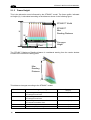
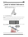
1
STS400™ Installation Manual Datalogic Automation S.r.l. Via Lavino, 265 40050 - Monte S. Pietro Bologna - Italy STS400™ Installation Manual Ed.: 03/2013 © 2013 Datalogic Automation S.r.l. ALL RIGHTS RESERVED. Protected to the fullest extent under U.S. and international laws. Copying, or altering of this document is prohibited without express written consent from Datalogic Automation S.r.l. Datalogic and the Datalogic logo are registered trademarks of Datalogic S.p.A. in many countries, including the U.S.A. and the E.U. Matrix 410, ID-NET, VisiSet and X-PRESS are trademarks of Datalogic Automation S.r.l. All other brand and product names mentioned herein are for identification purposes only and may be trademarks or registered trademarks of their respective owners. Datalogic shall not be liable for technical or editorial errors or omissions contained herein, nor for incidental or consequential damages resulting from the use of this material. 821002491 (Rev. A) CONTENTS REFERENCES .............................................................................................................v Conventions.................................................................................................................. v Reference Documentation ............................................................................................ v Support Through The Website...................................................................................... v Patents.......................................................................................................................... v COMPLIANCE.............................................................................................................vi EMC Compliance......................................................................................................... vi Power Supply............................................................................................................... vi LED Compliance.......................................................................................................... vi CE Compliance............................................................................................................ vi FCC Compliance ......................................................................................................... vi HANDLING.................................................................................................................vii GENERAL VIEW .......................................................................................................viii 1 1.1 1.2 1.3 1.3.1 1.4 1.5 1.6 INTRODUCTION ..........................................................................................................1 STS400™ - Solution for Tires Sorting .......................................................................... 1 Terminology ..................................................................................................................2 STS400™ Feasibility Requirements............................................................................. 3 Extracting Tire Size From Tire Sidewall Markings ........................................................ 5 STS400™ Model Descriptions...................................................................................... 6 Power Requirements .................................................................................................... 6 STS400™ Accessories.................................................................................................7 2 2.1 2.1.1 2.1.2 2.1.3 2.1.4 2.2 2.3 2.3.1 2.3.2 2.3.3 2.3.4 2.3.5 2.4 2.5 2.5.1 2.6 INSTALLATION ...........................................................................................................8 STS400™ Supporting Frame ....................................................................................... 8 Frame Width .................................................................................................................9 Frame Length ...............................................................................................................9 Frame Height ..............................................................................................................10 Frame Bill Of Materials ...............................................................................................11 Mechanical Dimensions.............................................................................................. 12 Mounting Distance (DOF) ...........................................................................................18 STS400-005, STS400-006, STS400-007, STS400-008 ............................................. 18 STS400-015, STS400-016, STS400-017, STS400-018 ............................................. 18 STS400-105, STS400-106, STS400-107, STS400-108 ............................................. 19 STS400-205, STS400-206 .........................................................................................19 STS400-305, STS400-306 .........................................................................................20 Supporting Profile Height Adjustment......................................................................... 21 STS400™ Main Plate Mounting .................................................................................22 STS400™Plate Support Assembly Positioning for Odd Number of Readers ............. 24 Presence Sensor Positioning...................................................................................... 26 3 3.1 3.2 3.3 3.3.1 3.4 3.5 3.5.1 ELECTRICAL CONNECTIONS .................................................................................29 STS400™ Wiring Diagram .........................................................................................29 CBX Connection Box Pinout....................................................................................... 30 Power Supply..............................................................................................................31 STS400-1xx Models ...................................................................................................31 M12-D 4-Pin Connector (Ethernet) ............................................................................. 31 Main Serial Interface...................................................................................................32 RS232 Interface..........................................................................................................33 iii 3.5.2 3.6 3.7 3.7.1 3.7.2 3.8 3.8.1 3.8.2 RS485 Full-Duplex Interface.......................................................................................34 Auxiliary RS232 Interface ...........................................................................................35 Digital Inputs ...............................................................................................................36 Presence Sensor Input Connections .......................................................................... 37 Input Connections From PLC ..................................................................................... 38 Digital Outputs ............................................................................................................39 Output Connections Using STS400™ Power ............................................................. 39 Output Connections to External Digital Inputs ............................................................ 40 4 4.1 4.2 4.2.1 4.2.2 4.2.3 4.2.4 4.3 DISPLAY MENUS ...................................................................................................... 41 Main Menu ..................................................................................................................42 View Menus ................................................................................................................42 Standard .....................................................................................................................43 Network State .............................................................................................................43 Reading Mask.............................................................................................................44 Init Counters ...............................................................................................................45 Extended Menu...........................................................................................................45 5 5.1 5.1.1 5.1.2 5.1.3 5.1.4 READING FEATURES...............................................................................................46 DOF and FOV Data ....................................................................................................46 Passenger Car/Light Truck Solutions ......................................................................... 46 Commercial Vehicle Solutions .................................................................................... 46 Bottom Reading Solutions ..........................................................................................46 Hook Chain (Side) Reading Solutions ........................................................................ 46 6 6.1 6.2 6.2.1 6.2.2 SOFTWARE CONFIGURATION................................................................................ 47 Default Configuration ..................................................................................................47 Backup & Restore Procedures ...................................................................................48 Using VisiSet™...........................................................................................................48 Using CBX500 ATS HMI Interface (Keypad/Display) ................................................. 49 7 7.1 7.2 MAINTENANCE .........................................................................................................50 STS400™: What You Can and Cannot Do................................................................. 50 Cleaning......................................................................................................................50 8 8.1 TROUBLESHOOTING ...............................................................................................51 General Guidelines .....................................................................................................51 9 TECHNICAL FEATURES........................................................................................... 52 iv REFERENCES CONVENTIONS This manual uses the following conventions: "User" refers to anyone using an STS400™ array. "Reader" refers to the Matrix 410™ ATS reader mounted on the STS400™ array. "You" refers to the System Administrator or Technical Support person using this manual to install, configure, operate, maintain or troubleshoot an STS400™ station. REFERENCE DOCUMENTATION For further details refer to: the VisiSet™ Help On Line, Matrix Reading Methods, Matrix Host Mode Programming, Matrix SW Parameter Guide, Matrix Code Quality Verifier Solution provided as supplementary documentation on Mini-DVD. SUPPORT THROUGH THE WEBSITE Datalogic provides several services as well as technical support through its website. Log on to www.datalogic.com and click on the Industrial Automation links for further information: Products - Industrial Automation - Identification Select your product from the links on the Identification page. The product page describes specific Info, Features, Applications, Models, Accessories, and Downloads including documentation, software drivers, and the VisiSet™ utility program, which allows device configuration using a PC through Serial and Ethernet interfaces. Support & Services - Industrial Automation Several links from the Industrial Automation list take you to additional services such as: Service Program which contains Maintenance Agreements and Warranty Extensions; Repair Centers; On-Line RMA Return Material Authorizations; Technical Support through email or phone, Partner Program; Downloads for additional downloads. PATENTS This product is covered by one or more of the following patents: Utility patents: US6512218B1, US6616039B1, US7053954B1, US8058600B2, US8289387B2, EP996284B1, EP999514B1, EP1014292B1, JP4435343B2, JP4571258B2, Additional patents pending. v COMPLIANCE For installation, use and maintenance it is not necessary to open the readers. Only connect Ethernet and dataport connections to a network which has routing only within the plant or building and no routing outside the plant or building. EMC COMPLIANCE In order to meet the EMC requirements: for CBX connections, connect the pin "Earth" to a good Earth Ground POWER SUPPLY ATTENTION: READ THIS INFORMATION BEFORE INSTALLING THE PRODUCT This product is intended to be installed by Qualified Personnel only. This product is intended to be connected to a UL Listed power supply which supplies power directly to the product. LED COMPLIANCE LED emission according to EN 62471. CE COMPLIANCE Warning: This is a Class A product. In a domestic environment this product may cause radio interference in which case the user may be required to take adequate measures. FCC COMPLIANCE Modifications or changes to this equipment without the expressed written approval of Datalogic could void the authority to use the equipment. This device complies with PART 15 of the FCC Rules. Operation is subject to the following two conditions: (1) This device may not cause harmful interference, and (2) this device must accept any interference received, including interference which may cause undesired operation. This equipment has been tested and found to comply with the limits for a Class A digital device, pursuant to part 15 of the FCC Rules. These limits are designed to provide reasonable protection against harmful interference when the equipment is operated in a commercial environment. This equipment generates, uses, and can radiate radio frequency energy and, if not installed and used in accordance with the instruction manual, may cause harmful interference to radio communications. Operation of this equipment in a residential area is likely to cause harmful interference in which case the user will be required to correct the interference at his own expense. vi HANDLING The STS400™ is designed to be used in an industrial environment and is built to withstand vibration and shock when correctly installed, however it is also a precision product and therefore before and during installation it must be handled correctly to avoid damage. avoid that the array is dropped. do not fine tune the positioning by striking the array. NO NO do not weld the array into position which can cause electrostatic, heat or reading window damage. do not spray paint near the array which can cause reading window damage. NO NO vii GENERAL VIEW STS400™ 1 2 5 3 4 3 Figure A - STS400-0x8 1 2 3 5 4 3 Figure B - STS400-108 1 2 3 5 4 3 Figure C - STS400-205, STS400-305 viii 1 ID-NET™ Master 3 Mounting Slots (4) 2 ID-NET™ Slaves 4 Positioning Slot 5 Reading Windows INTRODUCTION 1 1 INTRODUCTION 1.1 STS400™ - SOLUTION FOR TIRES SORTING STS400™, which means Solution for Tires Sorting, is a solution designed to be easily integrated into a sorting system for reading barcodes on the tires. STS400-005 Reading Station Tire Sorting Station The solution, made up of an array of Matrix 410™ ATS readers has been studied to be a premounted, pre-configured system entirely validated at the factory, in order to be quickly and easily installed by any technician. The STS400™ provides easy maintenance with a smart solution for fast replacement of any single Matrix 410™ ATS reader. There are a number of STS400™ models which can be chosen to satisfy all the customer needs in terms of: maximum code resolution, conveyor width and depth of field. Multiple Matrix 410™ ATS readers are combined in an array designed to cover a fixed conveyor or belt width at a fixed range of distances The readers are part of a Master/Slave high speed ID-NET™ network The Master collects the data from the Slaves, handles I/O and communicates with the host All external connections take place through the CBX500 ATS-001 connection box Two photoelectric sensors are included for triggering the reading phase. Alternatively the reading phase can be controlled by Host commands from the serial, Ethernet IP or Fieldbus interfaces. 1 STS400™ INSTALLATION MANUAL 1 1.2 TERMINOLOGY The manual will refer to some technical terms when explaining how to choose and install the STS400™. The following table will list the most used. Code Resolution Code Resolution is the width of the narrowest module (element) in a barcode, usually expressed in millimeters. It is also commonly expressed in mils, (thousandths of an inch). DOF DOF stands for Depth Of Field and it indicates the range (distance from the reader) where the barcode can be read. Resolution = Module width FOV FOV stands for Field Of View and describes the reading area at a given reading distance within the DOF. Front View Horizontal FOV defines the reading width of the STS400™ across the conveyor. Vertical FOV defines the reading length of the STS400™ parallel to the conveyor. Minim um Reading Distance DOF Maxim um Reading Distance The guaranteed reading volume is defined as: Horizontal FOV FOVHmin x FOVVmin x DOF Horizontal FOV on Code 128 codes from the Datalogic Test Chart. Top View Vertical FOV Tire Terminology Width It is the widest point from sidewall to sidewall of the tire. Height It is the difference from the external to the internal diameter of the tire. Diameter It is the internal diameter of the tire which will fit the car wheel rim. Bead It is the part of the tire which contacts the car wheel rim. The barcode is usually applied here. 2 Width Bead Height Diameter INTRODUCTION 1 1.3 STS400™ FEASIBILITY REQUIREMENTS In order to make the best STS400™ solution choice which fits the application needs, some basic information is required. Highest Application Code Resolution: this data is fundamental for choosing the STS400™ model. This information must be the minimum barcode module among all the barcodes to be read in the application. STS400™ is supplied for two nominal resolutions: High Resolution, resolution between 0.25 mm (10 mils) and 0.30 mm (12 mils) Standard Resolution, resolution lower than or equal to 0.30 mm (12 mils) Note: If the Resolution is higher than 0.25 mm (smaller module width), please contact your local Datalogic representative. Maximum Application DOF: this data corresponds to the difference between the maximum width (Wmax) and the minimum width (Wmin) among all the tires to be sorted: Maximum Application DOF W max W min W max Maximum Application DOF W min This information can be achieved by physically measuring the width of all tires to be sorted, and looking for the two limits. More easily, this information can be achieved by collecting all the tires size information printed on them. (See par. 1.3.1). STS400™ satisfies different ranges of DOF according to the code resolution and reading station application type: STS400™ Model STS400-01x STS400-00x STS400-10x STS400-20x STS400-30x Reading Station Type Top Reading Station High Resolution for Car/Light Truck Tires Top Reading Station Standard Resolution for Car/Light Truck Tires Top Reading Station Standard Resolution for Commercial Vehicle Tires Bottom Reading Station Hook Chain (Side) Reading Station Nominal DOF mm (in) 200 (7.9) 250 (9.8) 400 (15.7) 140 (5.5) 155 (6.1) 3 STS400™ INSTALLATION MANUAL 1 Conveyor Operating Width: This is the effective operative width where the tires can run: Operating Width Maximum Application FOV: This data is the maximum reading width where a barcode can be found by the STS400™. Because the barcode is located on or next to the Bead of the tire, the barcode will never be found at the edges of the Conveyor Operating Width. The Maximum Application FOV therefore can always be less than the Conveyor Operating Width: FOV Operating Width The figure above shows a sectional view of the tires in order to better understand the difference between the Maximum Application FOV and the Conveyor Operating Width. The Maximum Application FOV can be calculated with the following formula: FOV = Operating Width – 2 * (Minimum Tire Height – Barcode Position Margin) The Barcode Position Margin takes into account the distance from the Bead where the barcode could be applied. Maximum Conveyor Speed: The STS400™ with factory default configuration can support speeds up to 1 m/s (196.85 fpm, 60 m/min). Higher speeds can be obtained by modifying the configuration, please contact your local Datalogic representative for feasibility. NOTE 4 INTRODUCTION 1.3.1 1 Extracting Tire Size From Tire Sidewall Markings The best way to find out your tire size is to actually look at the tire sidewall. As you can see in the figure below, there is generally a lot of different information on the tire; however, for our purpose, we just need 3 pieces of information: 1. Tire Width: the “215” designation states the Width of the tire in millimeters at the widest point from sidewall to sidewall when mounted on the correct wheel. 2. Tire Height: the “65” designation is the Aspect Ratio. This ratio is calculated by dividing the section Height by the Width. Therefore the tire height is calculated as: Height = Ratio * Width / 100 3. Tire Diameter: the “15” designation is the Diameter of the wheel rim in inches. This is the exact size that the tire will fit. Once the whole list of the nominal values of all the tires has been collected, it is very easy to understand the application needs, and chose the correct STS400™ model. See the following sample table: W [mm] R [%] D [Inch] H [mm] Dint [mm] Dext [mm] Tire 1 120 70 12 84 304.8 472.8 Tire 2 175 65 14 114 355.6 583.1 Tire 3 185 55 14 102 355.6 559.1 Tire 4 205 60 15 123 381.0 627.0 Tire 5 205 65 15 133 381.0 647.5 Tire 6 190 50 17 95 431.8 621.8 Tire 7 100 100 18 100 457.2 657.2 Tire 8 275 45 18 124 457.2 704.7 Tire 9 275 45 20 124 508.0 755.5 Minimum [mm] 100.0 84.0 Maximum [mm] 275.0 133.3 508.0 755.5 DOF Required [mm] 175.0 Note: Dext is the external tire diameter. Even if this data is not used for the best choice of the STS400™, the above table shows it. It can be calculated as: Dext = Dint + (2 * H). 5 STS400™ INSTALLATION MANUAL 1 1.4 STS400™ MODEL DESCRIPTIONS Once the main specifications have been collected, it’s possible to choose the STS400™ model which best fits the application according to the following rules: Highest Application Code Resolution STS400™ Nominal Code Resolution Maximum Application DOF STS400™ Nominal DOF Maximum Application FOV STS400™ Nominal Horizontal FOV The models differ by Application Type, Code Resolution, and number of readers. STS400-XXX Ap plication T ype Cod e Resolution Reader s 0 = Top R eading Pas senger/Light Truck 0 = Standard (0.30 m m - 0.35 mm) 1 = H igh (0.25 mm) 5 6 7 8 1 = Top R eading Commerc ial Vehicles 2 = Bottom Reading 3 = Hook Chain (Side) Reading = 5x = 6x = 7x = 8x Matrix Matrix Matrix Matrix 410™ 410™ 410™ 410™ ATS ATS ATS ATS Single Matrix 410™ ATS-xxx models are used as stand alone readers having the same characteristics as the relative application type STS400™ models. They are also used as replacement readers for the relative STS400™ stations. The Reading Features of the various STS400™ models are given in chapter 5. 1.5 POWER REQUIREMENTS The STS400™ solution kit doesn’t include a power supply unit, which has to be ordered separately. The maximum power required depends on the model. Power is supplied to the system through its connection box CBX500 ATS. In the case of STS400-10x models, in addition to system power through the CBX500 ATS, the illuminator is supplied directly through the QL100 connectors. The following table indicates the compatible power supply to use according to the STS400™ model. The supply current consumption values are given considering the default parameter settings with the array working at maximum throughput. 6 INTRODUCTION 1 DC Supply Current Max @ 24 V ± 10% Model Peak Supply Current Max @ 24 V ± 10% Suggested Power Supply: PWR-120 or PG-120-K0x Bottom Reading Solution STS400-205 STS400-206 1.03 A 1.23 A 5.4 A for 2.8 ms 5.4 A for 2.8 ms 1.06 A 1.27 A 5.4 A for 3.1 ms 5.4 A for 3.1 ms Hook Chain (Side) Reading Solution STS400-305 STS400-306 Suggested Power Supply: PWR-240 Top Reading Passenger Car/Light Truck Solution STS400-0X5 STS400-0X6 STS400-0X7 STS400-0X8 1.13 A 1.35 A 1.58 A 1.80 A 5.4 A for 3.5 ms 5.4 A for 3.5 ms 7.2 A for 3.5 ms 7.2 A for 3.5 ms Suggested Power Supply: PWR-480A Top Reading Commercial Vehicle Solution STS400-105 STS400-106 STS400-107 STS400-108 1.43 A 1.71 A 2.00 A 2.28 A 16.2 A for 3.5 ms 16.2 A for 3.5 ms 21.6 A for 3.5 ms 21.6 A for 3.5 ms 1.6 STS400™ ACCESSORIES Accessory Description Order No. AC/DC Power Supply Kit (EU) AC/DC Power Supply Kit (UK) AC/DC Power Supply Kit (US) POWER UNIT 110/230VAC 24V 120 W POWER UNIT 110/230VAC 24V 240 W POWER UNIT 110/230VAC 24V 480 W 93ACC0046 93ACC0047 93ACC0048 93ACC1530 93ACC1070 93ACC1850 Ethernet TCP/IP Module STD/IP65 for CBX500 Profibus Module STD/IP65 for CBX500 DeviceNet Module IP65 for CBX500 Power Supplies PG-120-K01 PG-120-K02 PG-120-K03 PWR-120 PWR-240 PWR-480A Host Interface Modules BM200/BM210 BM300/BM310 BM400 BM500/BM510/BM520 Ethernet/IP Module STD/IP65/IP54 for CBX500 BM600 BM700/BM710 BM1100 BM1200/BM1210 CAN Open Module for CBX500 Profinet IO Module STD/IP65 for CBX500 CC-Link Module for CBX500 Modbus TCP Module STD/IP65 for CBX500 93ACC1851, 93ACC1852 93ACC1810, 93ACC1811 93ACC1814 93ACC1812, 93ACC1813, 93ACC1840 93ACC1815 93ACC1816, 93ACC1886 93ACC1845 93ACC1848, 93ACC1849 System Supervisor (up to 5 arrays) System Supervisor (up to 64 arrays) System Supervisor (up to 256 arrays) 93A100027 93A100028 93A100029 Software Management Datalogic WebSentinel-IMAGES 005 Datalogic WebSentinel-IMAGES 064 Datalogic WebSentinel-IMAGES 256 7 STS400™ INSTALLATION MANUAL 2 2 INSTALLATION 2.1 STS400™ SUPPORTING FRAME STS400™ has been optimized to be mounted on aluminum profiles. A frame made up of aluminum profiles allows the easiest and fastest mounting, and in most cases is the best choice. However, STS400™ can also be mounted on different supports like a fixed column. Because it is impossible to supply a standard frame which fits all the infinite needs of the customers, it must be designed during the feasibility study of the specific application. When studying a frame, it is suggested to design it with some safe margins for adjustment because of unforeseen changes at installation time like obstacles or different height requirements. Even if the STS400™ height can be calculated in advance, it is suggested to leave freedom on all three axes for fine adjustment in the field. The following figure shows how this can be achieved and is the type suggested by Datalogic. In this sample frame the STS400™ can be moved up-down, backward-forward, and left-right: The length of the aluminum profiles has to be dimensioned according to the following constraints: physical conveyor width conveyor height from floor to the tire reading plane Application DOF STS400™ model mimimum width (Wmin) of the tires The next three paragraphs suggest the formulas to be used for the frame dimensioning. 8 INSTALLATION 2.1.1 2 Frame Width The frame Width has to be calculated according to the distances shown in the following figure: STS Main Plate Dimensions STS Main Plate Max Side Room Max Side Room STS400-xx7 and -xx8 = 1065 mm (41.9 in) STS400-xx5 and -xx6 = 785 mm (30.9 in) Safe Conveyor Width Safe W The Safe clearance between the frame and the conveyor sides has to be chosen according to the Maximum Side Room available. It is suggested to always keep at least of 200 mm of Safe clearance. The length of the frame profiles W can be calculated in 2 ways, according to whether the STS400™ main plate is wider than the conveyor Conveyor Width or not: If Conveyor Width > STS Main Plate then: W = Conveyor Width + (2 * Safe Margin) If Conveyor Width STS Main Plate then: W = STS Main Plate + (2 * Safe Margin) Note: The STS400-xx7 models require a 70 or 55 mm shift to center the FOV over the conveyor and therefore must be accounted for in the frame width calculation. 2.1.2 Frame Length It is suggested to keep at least 500 mm of Safe clearance for the frame Length (L). This allows good frame stability and freedom for moving both the reading phase sensor(s) and the STS400™, forward or backward: Reading Phase Sensors L Note: There is not a specific calculation for (L). 9 STS400™ INSTALLATION MANUAL 2 2.1.3 Frame Height This is the dimension most influenced by the STS400™ model. The frame profile, indicated as Height (H), is calculated according to the distances shown in the following figure: STS400™ Width STS400™ Max Reading Distance H Wmin Foot Conveyor Height The STS400™ Maximum Reading distance is considered starting from the reader window surface to the maximum reading point: Max Reading Distance This distance changes according to the STS400™ model: STS400™ Model STS400-01x STS400-00x STS400-10x STS400-20x STS400-30x 10 Reading Station Type Top Reading Station High Resolution for Car/Light Truck Tires Top Reading Station Standard Resolution for Car/Light Truck Tires Top Reading Station Standard Resolution for Commercial Vehicle Tires Bottom Reading Station Hook Chain (Side) Reading Station Maximum Reading Distance mm (in) 910 (35.8) 1140 (44.9) 1280 (50.4) 457 (18) 560 (20) INSTALLATION 2 Finally the frame Height (H) can be calculated by the following formula: H = Conveyor Height + Wmin + Max Reading Distance + STS400 Width + Safe Length - Foot Where: Safe Length is an extra length of 50 to 100 mm on the top of the frame, used for fine adjustment at installation time (if needed); Foot is usually considered to be roughly 50 mm: 50 mm 2.1.4 Frame Bill Of Materials We suggest using Bosch aluminum profiles; although any other brand can fully satisfy this purpose. The 45 x 45 mm profile section is the best compromise between frame stability and price. The following bill of materials indicates a list of generic profiles: W, L and H. Description Profile W Profile L Profile H Angular brackets Quantity 3 6 4 20 Note: It is suggested to double the angular brackets on both the ends of the profile supporting the STS400™: Angular Brackets Once the frame has been fully mounted, the STS400™ can be mechanically mounted. 11 STS400™ INSTALLATION MANUAL 2 2.2 MECHANICAL DIMENSIONS STS400-005, STS400-205, STS400-305 392.5 [15.45] 140 [5.51] Ø65.0 [Ø2.54] 68.6 [2.70] 20 [0.79] 223 [8.78] 9 [0.35] 32.25 [1.27] 44.75 [1.76] 112.5 [4.43] 89 [3.50] 149 [5.87] 30 [1.18] 785 [30.91] STS400-015 392.5 [15.45] Ø65.0 [Ø2.54] 110 [4.33] 20 [0.79] 223 [8.78] 9 [0.35] 44.75 [1.76] 172.5 [6.79] 55 [2.17] 12 149 [5.87] 89 [3.50] 30 [1.18] 785 [30.91] INSTALLATION 2 STS400-105 140 [5.51] 68.6 [2.70] Ø100.0 [Ø3.94] 20 [0.79] 9 [0.35] 223 [8.78] 241 [9.48] 44.75 [1.76] 112.5 [4.43] 32.25 [1.27] 392.5 [15.45] 89 [3.50] 176 [6.93] 30 [1.18] 785 [30.91] STS400-006, STS400-206, STS400-306 392.5 [15.45] 140 [5.51] Ø65.0 [Ø2.54] 20 [0.79] 223 [8.78] 9 [0.35] 32.25 [1.27] 44.75 [1.76] 42.5 [1.67] 149 [5.87] 89 [3.50] 30 [1.18] 785 [30.91] 13 STS400™ INSTALLATION MANUAL 2 STS400-016 392.5 [15.45] Ø65.0 [Ø2.54] 110 [4.33] 20 [0.79] 223 [8.78] 9 [0.35] 44.75 [1.76] 117.5 [4.63] 89 [3.50] 149 [5.85] 30 [1.18] 785 [30.91] STS400-106 140 [5.51] Ø100.0 [Ø3.94] 20 [0.79] 9 [0.35] 223 [8.78] 241 [9.48] 44.75 [1.76] 42.5 [1.67] 32.25 [1.27] 392.5 [15.45] 785 [30.91] 800 [31.49] 14 INSTALLATION 2 Ø65 [Ø2.54] 140 [5.51] 20 [0.79] 9 [0.35] 223 [8.78] 182.5 [7.18] 70 [2.76] 44.7 [1.76] 532.5 [20.96] 32.2 [1.27] STS400-007 89 [3.50] 149 [5.87] 30 [1.18] 1065 [41.93] Ø65 [Ø2.54] 110 [4.33] 20 [0.79] 9 [0.35] 223 [8.78] 257.5 [10.14] 55 [2.17] 44.75 [1.76] 532.5 [20.96] 32.25 [1.27] STS400-017 1065 [41.94] 15 STS400™ INSTALLATION MANUAL 2 Ø100 [Ø3.94] 20 [0.79] 9 [0.35] 140 [5.51] 223 [8.78] 241 [9.48] 182.5 [7.19] 70 [2.76] 44.75 [1.76] 532.5 [20.96] 32.25 [1.27] STS400-107 1065 [41.93] 89 [3.50] 176 [6.93] 30 [1.18] 1072 [42.22] Ø65 [Ø2.54] 9 [0.35] 20 [0.79] 44.75 [1.76] 532.5 [20.96] 140 [5.51] 223 [8.78] 42.5 [1.67] 32.25 [1.27] STS400-008 16 149 [5.87] 89 [3.50] 30 [1.18] 1065 [41.93] INSTALLATION 2 147.5 [5.81] Ø65 [Ø2.54] 20 [0.79] 9 [0.35] 223 [8.78] 110 [4.33] 44.75 [1.76] 532.5 [20.96] 32.25 [1.27] STS400-018 1065 [41.94] 20 [0.79] 44.75 [1.76] Ø100 [Ø3.94] 9 [0.35] 140 [5.51] 532.5 [20.96] 223 [8.78] 241 [9.48] 42.5 [1.67] 32.25 [1.27] STS400-108 1065 [41.93] 176 [6.93] 89 [3.50] 30 [1.18] 1080 [42.52] 17 STS400™ INSTALLATION MANUAL 2 2.3 MOUNTING DISTANCE (DOF) 2.3.1 STS400-005, STS400-006, STS400-007, STS400-008 890 mm (35 in) Largest Tire Max. 250 mm (9.8 in) Smallest Tire Conveyor 2.3.2 STS400-015, STS400-016, STS400-017, STS400-018 710 mm (28 in) Largest Tire Max. 200 mm (7.9 in) Smallest Tire Conveyor 18 INSTALLATION 2.3.3 2 STS400-105, STS400-106, STS400-107, STS400-108 880 mm (34.6 in) Largest Tire Max. 400 mm (15.7 in) Smallest Tire Conveyor 2.3.4 STS400-205, STS400-206 Conveyor 317 mm (12.5 in) min nominal DOF DOF range = 317 mm (12.5 in) to 457 mm (18 in) 19 20 Hook Chain Max. 155 mm Max. (6.1 in) 2.3.5 Smallest Tire Largest Tire 405 mm (15.9 in) 2 STS400™ INSTALLATION MANUAL STS400-305, STS400-306 INSTALLATION 2 2.4 SUPPORTING PROFILE HEIGHT ADJUSTMENT The frame profile supporting the STS400™ must be positioned at the correct height in order to completely overlap the STS400™ nominal DOF to the application DOF. Note: The application DOF is the difference between the maximum tire width and the minimum tire width. If the DOF required by the application is less than the STS400™ nominal DOF, it’s strongly suggested to balance the overlap by keeping the centers of both DOFs coincident: Inst H Inst H Application DOF In the figure on the right, the STS400™ nominal DOF is perfectly overlapped and centered on the application DOF. The installation height (Inst H in the figure), which is the distance from the reader window surface to the conveyor plane is calculated by the following formula: Inst H = Tire_Wmin + (Application_DOF / 2) + DOFc_dist Where the DOFc_dist is the distance between the reader window surface and the center of the STS400™ DOF; this value changes according to the model: STS400™ Model STS400-01x STS400-00x STS400-10x STS400-20x STS400-30x Reading Station Type Top Reading Station High Resolution for Car/Light Truck Tires Top Reading Station Standard Resolution for Car/Light Truck Tires Top Reading Station Standard Resolution for Commercial Vehicle Tires Bottom Reading Station Hook Chain (Side) Reading Station Maximum Reading Distance mm (in) 810 (31.9) 1015 (40) 1080 (42.5) * 482.5 (19) * For Bottom reading stations the reading distance is a fixed value approximately equal to the top of the conveyor plane. Tire_Wmin is not significant, Application_DOF/2 is negligible. Inst H is typically set to the minimum reading distance, see par. 2.3.4. 21 STS400™ INSTALLATION MANUAL 2 2.5 STS400™ MAIN PLATE MOUNTING Once the supporting profile has been positioned at the correct height we can proceed with the STS400™ mechanical mounting. STS400™ has been designed to be easily installed by one person using the T-bolt, special plate supporting nut and locknut supplied in the kit: Figure 1- STS400™ Plate Supporting Nut The plate supporting nut has to be coupled to the frame with the M8 x 25 mm T-bolt: Figure 2- STS400™ Plate Support Assembly Mount the plate support assembly onto the bottom side of the STS400™ supporting frame. When the T-bolt is inserted into the profile slot, position it directly over the center 1 of the operating width and completely tighten the nut: 1 For STS400™ models having an even number of readers, the main plate slot, FOV and operating width are congruent. If the STS400™ model has an odd number of readers then an offset must be applied from the center of the operating width. See par. 2.5.1 for details. 22 INSTALLATION 2 Finally the STS400™ can be mounted onto the station frame. The STS400™ has to be installed onto the station frame in the conveyor direction so that the main plate slot (reader side) is aligned with the plate support assembly. Output Side Rear of Frame Conveyor Direction Slide the main plate slot between the plate support assembly and the supporting profile until it reaches the end. The plate support assembly can fully support the STS400™ weight without human help. 23 STS400™ INSTALLATION MANUAL 2 Fix the STS400™ using 4 T-bolts and nuts (not supplied) to the supporting profile. When the main plate slot is fully inserted onto the plate support assembly, the 4 mounting slots are aligned with the supporting profile groove: Fixing Slots to Frame Also screw the locknut onto the plate support assembly and tighten it. 2.5.1 STS400™Plate Support Assembly Positioning for Odd Number of Readers The STS400™ kits having an odd number of Matrix 410™ ATS readers are the -xx5 or -xx7 models. When mounting one of these models the plate support assembly can’t be fixed exactly over the center of the operating width because the main plate slot no longer corresponds to the center of the FOV. A positional offset must be applied to center the FOV over the operating width. The following figure shows what happens when the plate support assembly is centered over the operating width with an STS400™ model having an odd number of readers: 24 INSTALLATION 2 = = = = STS400-xx7 centered over conveyor It’s clear that the plate support assembly must have a positional offset from the center. Looking at the frame from the Output Side (tires coming out of the page), in order to align the center of the FOV with the center of the conveyor, an offset towards the left side has to be applied: = = STS400-xx7 with offset over conveyor The positional offset from the operating width center changes according to the STS400™ model used: STS400™ Model STS400-015 STS400-017 STS400-x05 STS400-x07 Reading Station Type High Resolution High Resolution Standard Resolution Standard Resolution Direction Offset mm (in) 55 (2.17) 55 (2.17) 70 (2.76) 70 (2.76) 25 STS400™ INSTALLATION MANUAL 2 2.6 PRESENCE SENSOR POSITIONING The STS400™ system comes with a pair of photocells that can be used to detect the presence of the tire on the conveyor and trigger the beginning and the end of the reading phase. When used, they must be positioned and mounted at the conveyor belt level depending on the size of the tires that must be handled. Position the presence sensors according to the following procedure: 1. Retrieve the size of the minimum tire height (Hmin) and the minimum tire width (Wmin) of the tires. 2. Determine the field of view along the conveyor direction (FOVv) at the maximum distance. See the table below. 3. If the minimum tire height (Hmin) is less than the FOVv/2 at the maximum distance, then both Reading Phase ON and Reading Phase OFF presence sensors are required and they must be mounted at the Hmin distance from the edges of the vertical FOV as shown in the figure below: Hmin = minimum tire height (lowest profile tire) Wmin = minimum tire width (narrowest tire) PS1 = Reading Phase ON Photocell PS2 = Reading Phase OFF Photocell max distance Tire Height FOVv @ max dist Hmin Tire Width PS1 Hmin Wmin PS2 Top Reading Station with Two Presence Sensors STS400™ Model STS400-01x STS400-00x STS400-10x STS400-20x STS400-30x 26 Reading Station Type Top Reading Station High Resolution for Car/Light Truck Tires Top Reading Station Standard Resolution for Car/Light Truck Tires Top Reading Station Standard Resolution for Commercial Vehicle Tires Bottom Reading Station Hook Chain (Side) Reading Station Vertical FOV @ Maximum Reading Distance mm (in) 190 (7.5) 240 (9.5) 270 (10.6) * see note 159 (6.3) INSTALLATION 2 In some cases the system can work with only one photocell. If the minimum tire height (Hmin) is greater than the FOVv/2 at the maximum distance, then only a single presence sensor is required and it must be mounted at the mid point of the field of view as shown in the figure below: Hmin = minimum tire height (lowest profile tire) Wmin = minimum tire width (narrowest tire) PS1 = Reading Phase ON/OFF Photocell max distance Tire Height FOVv @ max dist Tire Width Hmin Wmin PS1 Top Reading Station with Single Presence Sensor This configuration requires modifying the Master default Reading Phase OFF parameter to External Trigger Trailing Edge, Complete Read. NOTE 27 STS400™ INSTALLATION MANUAL 2 Hmin = minimum tire height (lowest profile tire) PS1 = Reading Phase ON/OFF Photocell Tire Height Tire Width Hmin PS1 FOVv @ inst dist Bottom Reading Station with Single Presence Sensor For Bottom Reading Stations installed at the minimum nominal DOF of 317 mm (12.5 in), the Vertical FOV is 145 mm (5.7 in). If allowed by the application, it is suggested to use this value for the conveyor gap in order to maximize the reading area. NOTE 28 Smaller gaps can be used and maximized by modifying the configuration, please contact your local Datalogic representative for feasibility. ELECTRICAL CONNECTIONS 3 3 ELECTRICAL CONNECTIONS 3.1 STS400™ WIRING DIAGRAM CABLE IN STS400™ KIT CABLE FROM CUSTOMER SIDE PRE-MOUNTED CABLE ON STS400™ Sensor 2 Sensor 1 (optional) CAB-ETH M05 CBX500 ATS-001 M Ethernet Host (RJ45) S S S S S CAB-MS03 CBL-1480-02 24Vdc Serial Host: RS232 Outputs: RS485 (optional) RS422 OUT1 OUT2 Figure 3 - STS400™ Array Wiring CBL-1480-02 to CBX500 ATS-001 CAB-LP-05 to 24 Vdc STS400-1xx models Figure 4 - STS400-1xx Additional Wiring See par. 3.3.1 for wiring illuminator power on STS400-1xx models. 29 STS400™ INSTALLATION MANUAL 3 3.2 CBX CONNECTION BOX PINOUT The STS400™s all connect to the CBX500 ATS-001 as shown in the previous diagram. The table below gives the pinout of the CBX terminal block connectors. Vdc GND Earth +V I1A I1B -V +V I2A I2B -V +V -V O1+ O1O2+ O2TX RX SGND REF ID+ IDShield CBX500 ATS Terminal Block Connectors Input Power Power Supply Input Voltage + Power Supply Input Voltage Protection Earth Ground Inputs Power Source – External Trigger External Trigger A (polarity insensitive) External Trigger B (polarity insensitive) Power Reference – External Trigger Power Source – Inputs Input 2 A (polarity insensitive) Input 2 B (polarity insensitive) Power Reference – Inputs Outputs Power Source - Outputs Power Reference - Outputs Output 1 + Output 1 Output 2 + Output 2 Auxiliary Interface Auxiliary Interface TX Auxiliary Interface RX Auxiliary Interface Reference ID-NET™ Network Reference ID-NET™ network + ID-NET™ network Network Cable Shield Main Interface RS485 RS232 Full-Duplex TX TX+ *RX+ RX RTS TX*RXCTS SGND SGND * Do not leave floating, see par. 3.5.2 for connection details. NOTE 30 To avoid electromagnetic interference when the reader is connected to a CBX connection box, verify the jumper positions in the CBX as indicated in its Installation Manual. ELECTRICAL CONNECTIONS 3 3.3 POWER SUPPLY Power is supplied through the CBX500 ATS spring clamp terminal pins as shown in Figure 5: Power Supply VGND V+ in Earth Ground Figure 5 - Power Supply Connections For all STS400™ models the power must be 24 Vdc only. See par. 1.5 for recommended power supplies. It is recommended to connect the array CHASSIS to earth ground (Earth) by setting the appropriate jumper in the CBX connection box. See the CBX Installation Manual for details. 3.3.1 STS400-1xx Models For STS400-1xx models, in addition to powering the system through the CBX500 ATS, power the illuminators using the CAB-LP-05 cable connected directly between the first QL100 and the 24 Vdc power source. Connect the Brown/White wires to Vdc and Black/Blue wires to GND. Connect the cable shield to Earth ground. 3.4 M12-D 4-PIN CONNECTOR (ETHERNET) An M12 D-Coded connector is provided for the on-board Ethernet connection. This interface is IEEE 802.3 10 BaseT and IEEE 802.3u 100 BaseTx compliant. 4 1 3 2 Figure 6 - M12 D-Coded Female Ethernet Network Connector M12 D-Coded Ethernet Network Connector pinout Pin 1 2 3 4 Name TX + RX + TX RX - Function Transmitted data (+) Received data (+) Transmitted data (-) Received data (-) 31 STS400™ INSTALLATION MANUAL 3 3.5 MAIN SERIAL INTERFACE CAUTION Do not connect to the Main Interface spring clamp terminals if using Host Interface Modules (Fieldbus) with the CBX500. The signals relative to the following serial interface types are available on the CBX spring clamp terminal blocks. The main serial interface type and its parameters (baud rate, data bits, etc.) can be defined by the user via VisiSet™ software. For more details refer to the "Communication" folder in the VisiSet™ Help On Line. Details regarding the connections and use of the interfaces are given in the next paragraphs. 32 ELECTRICAL CONNECTIONS 3.5.1 3 RS232 Interface The RS232 interface can be used for Point-to-Point connections. When it is connected to the host computer it allows both transmission of code data and reader configuration by VisiSet™. The following pins are used for RS232 interface connection: CBX500 ATS TX RX RTS CTS SGND Function Transmit Data Receive Data Request To Send Clear To Send Signal Ground It is always advisable to use shielded cables. The overall maximum cable length must be less than 15 m (49.2 ft). USER INTERFACE SGND RXD TXD CTS READER SGND TX RTS RX RTS CTS Figure 7 – RS232 Main Interface Connections Using Hardware Handshaking The RTS and CTS signals control data transmission and synchronize the connected devices. +V RTS -V START OF TRANSMISSION END OF TRANSMISSION DATA TRANSMISSION +V TX DATA -V DATA TRANSMISSION C1 C2 C3 C4 C5 TRANSMISSION STOPPED ENABLED +V CTS -V IDLE ENABLED DISABLED IDLE Figure 8 - RS232 Control Signals If the RTS/CTS handshaking protocol is enabled, the Matrix 410™ activates the RTS output to indicate a message is to be transmitted. The receiving unit activates the CTS input to enable the transmission. 33 STS400™ INSTALLATION MANUAL 3 3.5.2 RS485 Full-Duplex Interface The RS485 full-duplex (5 wires + shield) interface is used for non-polled communication protocols in point-to-point connections over longer distances (max 1200 m / 3940 ft) than those acceptable for RS232 communications or in electrically noisy environments. The CBX pinout follows: CBX500 ATS TX+ RX+ TXRXSGND Function RS485 Transmit Data + RS485 Receive Data + RS485 Transmit Data RS485 Receive Data Signal Ground USER INTERFACE RX485+ TX485+ SGND READER RX485- SGND TX+ TX485- RX+ TX- RX- Figure 9 - RS485 Full-duplex Connections For applications that do not use RX485 signals, do not leave these lines floating but connect them to SGND as shown below. NOTE USER INTERFACE RX485+ SGND READER RX485- SGND TX+ TX- Figure 10 - RS485 Full-duplex Connections using Only TX Signals 34 ELECTRICAL CONNECTIONS 3 3.6 AUXILIARY RS232 INTERFACE The RS232 auxiliary interface is available for Point-to-Point connections. When it is connected to the host computer it allows both transmission of code data and reader configuration by VisiSet™. The parameters relative to the aux interface (baud rate, data bits, etc.) as well as particular communication modes such as LOCAL ECHO can be defined through the Communication folder of the VisiSet™ utility program. The 9-pin female Auxiliary Interface connector inside the CBX is the preferred connector for device configuration or communication monitoring. 1 5 9 6 Figure 11 - 9-pin female connector If permanent system wiring is required, the following pins are used to connect the RS232 auxiliary interface: CBX500 ATS RX TX SGND Function Auxiliary Interface Receive Data Auxiliary Interface Transmit Data Auxiliary Interface Reference USER INTERFACE RX TX Reference Figure 12 - RS232 Auxiliary Interface Connections Do not connect the Aux Interface to the CBX spring clamp connectors and the 9-pin connector simultaneously. NOTE 35 STS400™ INSTALLATION MANUAL 3 3.7 DIGITAL INPUTS There are two optocoupled polarity insensitive inputs available on the reader: Input 1 (External Trigger) and Input 2, a generic input: These inputs can be used to control (start/stop) the reading phase: Parameter Source Reading Phase ON Input Reading Phase OFF Input Single Presence Sensor External Trigger Leading Edge External Trigger Trailing Edge Two Presence Sensors External Trigger Leading Edge Input 2 Leading Edge PLC Digital Output External Trigger Leading Edge or Input 2 Leading Edge External Trigger Trailing Edge or Input 2 Trailing Edge NOTE Alternatively, host communication output commands (Serial or Fieldbus) can be used to control the reading phase. See the Configuration Parameters Help On Line for details. The electrical features of both inputs are: VAB = 30 Vdc max. IIN = 10 mA (reader) + 12 mA (CBX) max. The active state of these inputs is selected in software. Refer to the VisiSet™ Help On Line. An anti-disturbance filter is implemented in software on both inputs so that the minimum pulse duration is 0.5 milliseconds. This value can be increased through the software parameter Debounce Filter, see the Digital I/O folder in the VisiSet™ Help On Line for further details. These inputs are optocoupled and can be driven by PNP type commands. Polarity insensitive inputs assure full functionality even if pins A and B are exchanged. NOTE 36 ELECTRICAL CONNECTIONS 3.7.1 3 Presence Sensor Input Connections CAUTION Power is available directly to the Input Device, independently from the Power Supply Switch inside the CBX. The sensors included in the STS400™ have a standard pinout (brown = +Vdc; blue = GND; black = switched) and can be connected to the Trigger and Input 2 as shown in the figures below. Sensor 1 brown black blue CBX500 ATS Row 2 +V I1A I1B -V (bridge to I1B) Function Power Source - External Trigger External Trigger A (polarity insensitive) External Trigger B (polarity insensitive) Power Reference - External Trigger Presence Sensor Photocell (PNP) (brown) (black) (blue) Figure 13 – Presence Sensor Connected to External Trigger The yellow Trigger LED on the reader is on when the active state of the External Trigger corresponds to ON. Sensor 2 brown black blue CBX500 ATS Row 3 +V I2A I2B -V (bridge to I2B) Function Power Source - Inputs Input 2 A (polarity insensitive) Input 2 B (polarity insensitive) Power Reference - Inputs Presence Sensor Photocell (PNP) (brown) (black) (blue) Figure 14 – Presence Sensor Connected to Input 2 37 STS400™ INSTALLATION MANUAL 3 3.7.2 Input Connections From PLC Alternatively, the reading system can be controlled by a digital output of a PLC. For this purpose, connect the switched signal and the appropriate reference level as shown in the figures below. PLC Signal Input Reference CBX500 ATS Row 2 I1A I1B Function External Trigger A (polarity insensitive) External Trigger B (polarity insensitive) PLC Signal Input Signal Pulled down to External Input Reference Figure 15 - External Trigger Connected to PLC The yellow Trigger LED on the reader is on when the active state of the External Trigger corresponds to ON. PLC Signal Input Reference CBX500 ATS Row 3 I2A I2B Function Input 2 A (polarity insensitive) Input 2 B (polarity insensitive) PLC Signal Input Signal Pulled down to External Input Reference Figure 16 - Input 2 Connected to PLC 38 ELECTRICAL CONNECTIONS 3 3.8 DIGITAL OUTPUTS Two optocoupled general purpose outputs are available. The meaning of the two outputs Output 1 and Output 2 can be defined by the user. They are typically used to signal the data collection result. They are also available to the Host (either serial or Fieldbus) to be driven independently. The electrical features of the two outputs are the following: VCE = 30 Vdc max. ICE = 40 mA continuous max.; 130 mA pulsed max. VCE saturation = 1 Vdc max. @ 10 mA PD = 80 mW Max. @ 45 °C ambient temp. By default, Output 1 is associated with the Partial Read and No Read events, which activates when the code(s) signaled by the external trigger are not decoded, and Output 2 is associated with the Complete Read event, which activates when all the selected codes are correctly decoded. The output signals are fully programmable being determined by the configured Activation/Deactivation events, Deactivation Timeout or a combination of the two. Refer to the Digital I/O folder in the VisiSet™ Help On Line for further details. 3.8.1 Output Connections Using STS400™ Power CAUTION Power is available directly to the Output Device, independently from the Power Supply Switch inside the CBX. The digital outputs can power and drive small devices meeting the electrical characteristics above such as electronic switches which can then manage larger power consuming devices such as signaling lights or other machinery. CBX500 ATS +V O1+ O1O2+ O2-V Function Power Source - Outputs Output 1 + Output 1 Output 2 + Output 2 Power Reference Outputs Output Device Power to Output device Output Signal Output device Reference Figure 17 - Open Emitter Output Using STS400™ Power 39 STS400™ INSTALLATION MANUAL 3 Output Device Power to Output device Output device Reference Output Signal Figure 18 - Open Collector Output Using STS400™ Power 3.8.2 Output Connections to External Digital Inputs Alternatively, the reading system's digital outputs can be used to control a digital input of another device such as a PLC. For this purpose, connect the switched signal and the appropriate reference level as shown in the figures below. CBX500 ATS O1+ O1O2+ O2- Function Output 1 + Output 1 Output 2 + Output 2 Digital Input Pulled up to Digital Input Power Output Signal Figure 19 - Output Connected to External Digital NPN Input Digital Input Output Signal Pulled down to Digital Input Reference Figure 20 - Output Connected to External Digital PNP Input 40 DISPLAY MENUS 4 4 DISPLAY MENUS NOTE While working on the display the complete reading station is offline. The Offline state means that no readings are performed, no data is transmitted to the PLC and any connection to WebSentinel will be lost. The display menus allow you to: change the messages on the display (View), perform backup and restore, and reset the counters. If the reading station is turned on and the system is ready, the master-reader shows the most important values on the display. Matrix 410 ATS-XXX 6.xx SYN M00 SN XXXXXXXXX ETH XXX.XXX.XXX.XXX The display can be used with the three buttons below it. The up arrow button allows you to scroll up through the menu. The down arrow button allows you to scroll down through the menu. With the middle button, you can confirm your selection. To access the menus, press the two outermost buttons simultaneously for several seconds. 41 STS400™ INSTALLATION MANUAL 4 4.1 MAIN MENU To enter the Menu press the Up and Down buttons simultaneously. The menu structure is shown below. Menu: [Exit] (exits HMI Interface menu) Test Mode Focus/Locate Calibration Code Setting View Extended (enters Extended menu) Extended: [Exit] (returns to Main menu) Backup Yes (performs Backup - uninterruptible) No (returns to Extended menu) Restore Yes (performs Restore - uninterruptible) No (returns to Extended menu) To move through the list press and release the Up or Down key. To select an item or enter a submenu, press and release the Enter key. After executing an HMI function the display shows a result message and then automatically exits from the menu structure. To exit a menu, press and release the Enter key at the [Exit] item. To exit from a running HMI function, press and release the Enter key. These functions will also exit upon their configured timeout. 4.2 VIEW MENUS This menu item is only visible if the connected reader is set as master. NOTE Using this menu item, you can select between different views to be shown on the display. 42 DISPLAY MENUS 4.2.1 4 Standard In this standard view the following content will be shown on the display: Row 1: Reading Result Rows 2 and 3: Code Content Row 4: Number of digits in code and Angle of code in image Good Read Good 1234567890 0010 Dgt 351 Deg No Read No Read Reading ... Reading Active 4.2.2 Network State In this view the state of the slave readers, connected to the ID-NET™ network, can be checked. Below the address number the status of the reader is displayed as a symbol. No Error 1 Network 15 *****---------16 Network 31 --------------- Slave 2 missing 1 Network 15 *?***---------16 Network 31 --------------- * = Reader with no error ! = Reader with an error ? = Reader missing in ID-NET network 43 STS400™ INSTALLATION MANUAL 4 4.2.3 Reading Mask In VisiSet™, if the Array Layout Monitor parameter in the Display folder is enabled, it changes the appearance of the reading mask. Array Layout Monitor Enabled If the Array Layout Monitor parameter is enabled, on row one, the display shows the result of the reading phase: code content, or read event message. Row two shows the reading phase counter and read rate counting from the last restart of the system. These values are reset if the reader configuration is changed or a manual reset of the statistics is performed (Init Counters). On row three, the reading mask for the master and slave readers (ordered from left to right) is shown with the numbers 0 and 1. A successful read is presented as a 1 for the readers who have read the code. The network state on row four has the same meaning as in par. 4.2.2. Row 1: Last Reading Result Row 2: Reading Phase Count and Statistics Row 3: Reading Mask Row 4: Network State Good Read Master and Slave 1 1234567890 P=0000001 GR=100.00% 110000000000000 *****---------- Good Read Slave 3 and Slave 4 1234567890 P=0000001 GR=100.00% 000110000000000 *****---------- No Read No Read P=0000002 GR=50.00% 000000000000000 *****---------- Array Layout Monitor Disabled If the Array Layout Monitor parameter is disabled, on row one, the display shows the result of the reading phase: code content, or read event message. Row two shows the reading statistics based on the last 100 reading phases: Good Read, No Read, Multiple Read (more codes read than expected) and Partial Read (less codes read than expected). The percentages range from 00 to 99. On row three (and four which is not used for STS400™), the reading mask for the master and slave readers (ordered from left to right) is shown with the numbers 0 and 1. A successful read is presented as a 1 for the readers who have read the code. 44 DISPLAY MENUS 4 Row 1: Last Reading Result Row 2:Statistics Rows 3 and 4: Reading Mask Good Read Master and Slave 1 1234567890 G99% N01% M00% P00% 110000000000000 000000000000000 Good Read Slave 3 and Slave 4 1234567890 G99% N01% M00% P00% 000110000000000 000000000000000 No Read No Read G99% N01% M00% P00% 000000000000000 000000000000000 4.2.4 Init Counters This menu item is only visible if the connected reader is set as master and the Array Layout Monitor parameter is enabled. NOTE Use the following procedure to reset the Reading Mask statistics to 0: 1. Enter the Menu (by pressing the two arrow buttons simultaneously) 2. Select the "View" item with the arrow buttons and confirm with the middle button. 3. Select the "Init Counters" item with the arrow buttons and confirm with the middle button. 4.3 EXTENDED MENU Through this menu item the parameters and calibrations of the complete system will be backed up or restored in the BM100 backup module inside the CBX500 ATS-001. To perform this procedure, see par. 6.2.2. 45 STS400™ INSTALLATION MANUAL 5 5 READING FEATURES 5.1 DOF AND FOV DATA 5.1.1 Passenger Car/Light Truck Solutions PN Description Readers Code Resolution Focus Distance qty mm (mils) mm (in) Min Reading Distance mm (in) Max Reading Distance mm (in) Vertical FOV Horizontal FOV @ min distance @ min distance mm (in) mm (in) 937401023 STS400-005 5 937401024 STS400-006 6 937401025 STS400-007 7 937401026 STS400-008 8 1225 (48.2) 937401027 STS400-015 5 635 (25) 937401028 STS400-016 6 937401029 STS400-017 7 937401030 STS400-018 8 5.1.2 Description 0.25 (10) 1065 (41.9) 788 (31) 890 (35) 710 (28) 1140 (44.9) 910 (35.8) 184 (7.2) 146 (5.7) 945 (37.2) 1085 (42.7) 745 (29.3) 855 (33.7) 965 (38) Readers Code Resolution Focus Distance qty mm (mils) mm (in) 937401037 STS400-105 5 937401038 STS400-106 6 937401039 STS400-107 7 937401040 STS400-108 8 Min Reading Distance mm (in) Max Reading Distance mm (in) Vertical FOV Horizontal FOV @ min distance @ min distance mm (in) mm (in) 805 (31.7) 0.35 (14) 1065 (41.9) 880 (34.6) 1280 (50.4) 184 (7.2) 945 (37.2) 1085 (42.7) 1225 (48.2) Bottom Reading Solutions PN Description mm (in) Min Reading Distance mm (in) Max Reading Distance mm (in) 380 (15) 317 (12.5) Readers Code Resolution Focus Distance qty mm (mils) 0.30 (12) 937400018 STS400-205 5 937400019 STS400-206 6 5.1.4 0.30 (12) Commercial Vehicle Solutions PN 5.1.3 805 (31.7) Vertical FOV Horizontal FOV @ min distance @ min distance mm (in) mm (in) 457 (18) 145 (5.7) 754 (29.7) Max Reading Distance mm (in) Vertical FOV Horizontal FOV @ min distance @ min distance 560 (22) 894 (35.2) Hook Chain (Side) Reading Solutions PN Description Readers Code Resolution Focus Distance qty mm (mils) mm (in) Min Reading Distance mm (in) 0.30 (12) 483 (19) 405 (15.9) 937400020 STS400-305 5 937400021 STS400-306 6 mm (in) mm (in) 141 (5.6) 748 (29.4) 888 (35) DOF = Max Reading Distance - Min Reading Distance Guaranteed Reading Volume = FOVHmin x FOVVmin x DOF on Code 128 codes from the Datalogic Test Chart 46 SOFTWARE CONFIGURATION 6 6 SOFTWARE CONFIGURATION 6.1 DEFAULT CONFIGURATION The factory default configuration for the STS400™ is given here for reference: MASTER READER CONFIGURATION The following gives an excerpt of the relevant configuration parameters READING SYSTEM LAYOUT: Device Network Setting = Alone o ID-NET Topology Role = Master (synchronized) Expected Slave Device = xx Link Failure Timeout (ms) = 10000 OPERATING MODES: Operating Mode = Phase Mode Reading Phase ON = Ext. Trigger Leading Edge Acquisition Trigger = Continuous Reading Phase OFF = Input 2 Trailing Edge, Complete Read Image Acquisition Buffer Size = 20 CALIBRATION Exposure Time (x10us) = Gain = Gain Increasing = x1 Actual Calibration default parameter values depend on STS400™ model and can be modified to improve reading rate in the specific application. IMAGE PROCESSING Processing Mode = Advanced Code Setting Image Processing Timeout (ms) 100 1D CODES: Minimum Code Height (mm) = 5 Tires Improvement = Method 2 (Sigma ROI) to optimize code location and minimize processing time in case of low height barcodes Code search priority = Horizontal/Vertical (even and odd Slave nodes alternate Horizontal/Vertical and 45 Degrees) to optimize code location in case of low height barcodes DATA COLLECTION Minimum Phase Duration (ms) = (presence sensor debounce filter may be modified to eliminate false reading Phases) 47 STS400™ INSTALLATION MANUAL 6 SLAVE READERS CONFIGURATION Same configuration as master except for the following: READING SYSTEM LAYOUT: Device Network Setting = Alone o ID-NET Topology Role = Slave (synchronized) Slave Address = 1,2,3, … OPERATING MODES Acquisition Trigger Delay for SLAVES 1,3, 5,… (odd nodes) Status = Enabled Delay Time (x100us) = 20 Acquisition Trigger Delay for SLAVES 2,4,… (even nodes) Status = Disabled 1D CODES: Code search priority = 45 Degrees (odd nodes) Horizontal/Vertical (even nodes) NOTE In addition to the above parameters, the master reader may require changes to the setup parameters that handle the communications between the STS400™ and the host computer. Refer to the Matrix 410 Reference Manual and VisiSet™ Help-On-Line for the details. 6.2 BACKUP & RESTORE PROCEDURES The STS400™ factory default parameter settings are already stored in the External Memory (BM100 module) inside the CBX500 ATS connection box. After installation, changes to these parameters must be backed up, overwriting the factory settings. Additionally, backup files can be created for each specific reader on the STS400™ and saved to a PC. 6.2.1 Using VisiSet™ The VisiSet™ configuration tool provides the most comprehensive method of calibration and system configuration is the preferred method for making parameter changes. It also provides an easy method for performing configuration Backup and Restore. 48 SOFTWARE CONFIGURATION 6 Backup Procedure 1. Make sure the Write Protection switch (inside the CBX500 ATS) on the BM100 is unlocked. 2. While VisiSet™ is connected to the Master reader, select the Backup item from the Device Menu in confirm by clicking the Yes button. 3. During the procedure, messages appear on the VisiSet™ terminal window showing the progress and at the end the final results. 4. Set the Write Protection switch on the BM100 to locked. Restore Procedure 1. While VisiSet™ is connected to the Master reader, select the Restore item from the Device Menu in confirm by clicking the Yes button. 2. During the procedure, messages appear on the VisiSet™ terminal window showing the progress and at the end the final results. Backup Files to PC VisiSet™ also allows Backup to be performed through the ID-NET™ network to .ini files, saving them to the local PC. See the VisiSet™ Help On Line file under "ID-NET™ Backup to File Through Master" for details on this procedure. 6.2.2 Using CBX500 ATS HMI Interface (Keypad/Display) Up Enter Down Figure 21 – CBX500 ATS Keypad Through the CBX500 ATS keypad and display, you can perform the Backup and Restore functions from the "Extended" menu. See chapter 4 for details on entering the Extended menu. Backup Procedure 1. Make sure the Write Protection switch (inside the CBX500 ATS) on the BM100 is unlocked. 2. Select the Backup item from the Extended menu and press the Enter key on the Yes item. 3. When the procedure is complete a message appears on the display showing the results (Done or Error). 4. Set the Write Protection switch to locked. Restore Procedure 1. Select the Restore item from the Extended menu and press the Enter key on the Yes item. 2. When the procedure is complete a message appears on the display showing the results (Done or Error). 49 STS400™ INSTALLATION MANUAL 7 7 MAINTENANCE 7.1 STS400™: WHAT YOU CAN AND CANNOT DO The STS400™ comes pre-assembled, configured, calibrated and tested. Very few changes may be needed (and are allowed) to adapt the system to the plant operating conditions. Several changes are not permitted and if they are carried out the warranty is automatically void. If necessary, the readers’ configuration can be altered, but this should be done only according to the indications in chapter 6. The Matrix 410™ ATS readers are self-contained units (unique part #) and must not be disassembled. In the event of a faulty unit, it must be replaced with another Matrix 410™ ATS. The Matrix 410™ ATS lens cover must not be unscrewed or removed. A warranty seal is present that voids warranty if broken. The Matrix 410™ ATS lens must not be tampered with to alter the focus/diaphragm adjustment. The Matrix 410™ ATS internal illuminator must not be unscrewed or removed. 7.2 CLEANING Clean the reading windows periodically for continued correct operation of the array (see General Views, 5). Dust, dirt, etc. on the window may alter the reading performance. Repeat the operation frequently in particularly dirty environments. Use soft material and alcohol to clean the window and avoid any abrasive substances. 50 TROUBLESHOOTING 8 8 TROUBLESHOOTING 8.1 GENERAL GUIDELINES When wiring the device, pay careful attention to the signal name (acronym) on the CBX100/500 spring clamp connectors (chp. 3). If you need information about a certain reader parameter you can refer to the VisiSet program help files; either connect the device and select the parameter you’re interested in by pressing the F1 key, or select Help>Paramters Help from the command menu. If you’re unable to fix the problem and you’re going to contact your local Datalogic office or Datalogic Partner or ARC, we suggest providing (if possible): Application Program version, Parameter Configuration file, Serial Number and Order Number of your reader. You can get this information while VisiSet™ is connected to the reader: the Application Program version is shown in the Terminal Window; the Parameter Configuration can be saved to an .ini file applying the File>Save Configuration File command in the Parameter Setup window; Serial Number and Order Number can be obtained by applying the respective command in the Tools menu. Troubleshooting Guide for STS400™ Solutions Problem Suggestion Presence Sensor: Check the LED’s on the presence sensor. If the sensor has the sensors (light barrier) is power, a green LED must be lit. If the sensor has a free not working correctly. path (view) to the reflector, only this green LED should be lit. If a yellow LED is lit together with the green one, please check the mechanical position and orientation of the sensor and reflector. Every time the yellow LED on the sensor is lit, the corresponding LED in the CBX500 ATS connection box must be lit. For Trigger this must be the yellow LED and for Input 2 the green one. Is this is not the case, please check the wiring of the sensors. No Presence Sensor: Every time if a signal from PLC is correct in the CBX500 No trigger signal from the ATS connection box, a yellow LED (Trigger) must be lit PLC (If no sensor is used.) inside of this box. If this is not the case, please check the wiring and the output of the PLC. No Trigger Signal at If a reading signal (trigger signal) is present and active from Reader: the sensor or PLC and the LEDs in the CBX500 ATS Is the trigger signal correctly connection box are working correctly, the trigger signal recognized by the readers? LED on the reader must also be lit. As long as this LED is lit, the readers try to read a code. If this LED does not light, please replace the reader and send it to repair. Does the internal lighting If a trigger signal is active and no code is present under the system work correctly? system, all readers must flash blue or red. If this is not the case please replace the reader and send it to repair. Do the readers read codes? Place a correctly positioned code under each reader. If the reader has read the code, the its GOOD read (green) LED must light. Also a green spot must light at the code surface. If this is not the case, please replace the reader and send it to repair. 51 STS400™ INSTALLATION MANUAL 9 9 TECHNICAL FEATURES ELECTRICAL FEATURES Power Supply Voltage Consumption Communication Interfaces Main - RS232 - RS485 full-duplex Auxiliary - RS232 ID-NET™ Ethernet Inputs Input 1(External Trigger) and Input 2 Max. Voltage Max. Input Current Outputs Output 1 and Output 2 VOut (ILoad = 0 mA) Max. VOut (ILoad = 10 mA) Max. PD = VOut ILoad Max. OPTICAL FEATURES Image Sensor Image Format Frame Rate Pitch Tilt Lighting System LED Emmission ENVIRONMENTAL FEATURES Operating Temperature Storage Temperature Max. Humidity Protection Class - EN 60529 24 Vdc See par. 1.5 2400 to 115200 bit/s 2400 to 115200 bit/s 2400 to 115200 bit/s Up to 1MBaud 10/100 Mbit/s Opto-coupled and polarity insensitive 30 Vdc 10 mA Opto-coupled 30 Vdc 1.8 Vdc 170 mW CCD UXGA (1600x1200) 15 frames/sec. 35° 0° - 360° Internal Illuminator according to EN 62471 0 to 50 C (32 to 122 °F) -20 to 70 C (-4 to 158 °F) 90% non condensing IP65 * * when correctly connected to cables with seals and protection caps. 52 TECHNICAL FEATURES PHYSICAL FEATURES Dimensions: STS400-0x5, -0x6 STS400-105 STS400-106 STS400-0x7, -0x8 STS400-107 STS400-108 Weight: Mounting Plate Reader + Bracket Pre-mounted Cables ID-NET Cables and Terminator QLs 9 785 x 223 x 149 mm (30.91 x 8.78 x 5.87 in.) 785 x 241 x 176 mm (30.91 x 9.49 x 6.93 in.) 800 x 241 x 176 mm (31.50 x 9.49 x 6.93 in.) 1065 x 223 x 149 mm (41.93 x 8.78 x 5.87 in.) 1072 x 241 x 176 mm (42.20 x 9.49 x 6.93 in.) 1080 x 241 x 176 mm (42.52 x 9.49 x 6.93 in.) 5-6 readers 4100 g (9.04 lbs) 7-8 readers 5450 g (12.02 lbs) Matrix 410 ATS-000 about 610 g (1.34 lbs) each Matrix 410 ATS-100 about 880 g (1.94 lbs) each CAB-MS003 100 g (3.53 oz) each CAB-L003 66 g (2.33 oz) each CBL-1480-003 48 g (1.69 oz) each CBL-1490 Terminator 16 g (0.56 oz) QL100 115 g (4.06 oz) each QL150 123 g (4.34 oz) each To calculate the weight of your specific STS400 model, add the weights of the individual components from those listed above in the quantity present on your model. SOFTWARE FEATURES Readable Code Symbologies 1-D and stacked PDF417 Standard and Micro PDF417 Code 128 (GS1-128) Code 39 (Standard and Full ASCII) Code 32 MSI Standard 2 of 5 Matrix 2 of 5 Interleaved 2 of 5 Codabar Code 93 Pharmacode EAN-8/13 - UPC-A/E (including Addon 2 and Addon 5) GS1 DataBar Family Composite Symbologies Operating Mode Configuration Methods Parameter Storage 2-D Data Matrix ECC 200 (Standard, GS1 and Direct Marking) QR Code (Standard and Direct Marking) Micro QR Code MAXICODE Aztec Code POSTAL Australia Post Royal Mail 4 State Customer Kix Code Japan Post PLANET POSTNET POSTNET (+BB) Intelligent Mail Swedish Post PHASE MODE Windows-based SW (VisiSet™) via serial or Ethernet link Serial Host Mode Programming sequences Permanent memory (Flash) USER INTERFACE LED Indicators Power, Ready, Good; Trigger; Com, Status, (Ethernet Network); (Green Spot) 53 DECLARATION OF CONFORMITY EC-124 Rev.: 4 Pag.: 1 di 1 Datalogic Automation S.r.l. Via Lavino 265 40050 Monte San Pietro Bologna - Italy www.automation.datalogic.com declares that the MATRIX 410; 2D Imager and all its models are in conformity with the requirements of the European Council Directives listed below: 2004 / 108 / EC EMC Directive ______________________________________________ This Declaration is based upon compliance of the products to the following standards: EN 55022 ( CLASS A ITE ), DECEMBER 2010: INFORMATION TECHNOLOGY EQUIPMENT RADIO DISTURBANCE CHARACTERISTICS LIMITS AND METHODS OF MEASUREMENTS EN 61000-6-2, SEPTEMBER 2005: ELECTROMAGNETIC COMPATIBILITY (EMC) PART 6-2: GENERIC STANDARDS - IMMUNITY FOR INDUSTRIAL ENVIRONMENTS Monte San Pietro, January 23th, 2012 Paolo Morselli Quality Manager UNI EN ISO 14001 DECLARATION OF CONFORMITY EC-127 Rev.: 1 Pag.: 1 di 1 Datalogic Automation S.r.l. Via Lavino 265 40050 Monte San Pietro Bologna - Italy www.automation.datalogic.com declares that the CBX100; Connection Box Compact CBX500; Connection Box Modular BM100; Backup module BM150; Display module and all its models are in conformity with the requirements of the European Council Directives listed below: 2004 / 108 / EC EMC Directive ______________________________________________ This Declaration is based upon compliance of the products to the following standards: EN 55022 ( CLASS A ITE ), DECEMBER 2010: INFORMATION TECHNOLOGY EQUIPMENT RADIO DISTURBANCE CHARACTERISTICS LIMITS AND METHODS OF MEASUREMENTS EN 61000-6-2, SEPTEMBER 2005: ELECTROMAGNETIC COMPATIBILITY (EMC) PART 6-2: GENERIC STANDARDS - IMMUNITY FOR INDUSTRIAL ENVIRONMENTS Monte San Pietro, January 20th, 2012 Paolo Morselli Quality Manager UNI EN ISO 14001 DECLARATION OF CONFORMITY EC-128 Rev.: 2 Pag.: 1 di 1 Datalogic Automation S.r.l. Via Lavino 265 40050 Monte San Pietro Bologna - Italy www.automation.datalogic.com declares that the QLxxx and QLMxxx; Connection module and all its models are in conformity with the requirements of the European Council Directives listed below: 2004 / 108 / EC EMC Directive ______________________________________________ This Declaration is based upon compliance of the products to the following standards: EN 55022 ( CLASS A ITE ), DECEMBER 2010: INFORMATION TECHNOLOGY EQUIPMENT RADIO DISTURBANCE CHARACTERISTICS LIMITS AND METHODS OF MEASUREMENTS EN 61000-6-2, SEPTEMBER 2005: ELECTROMAGNETIC COMPATIBILITY (EMC) PART 6-2: GENERIC STANDARDS - IMMUNITY FOR INDUSTRIAL ENVIRONMENTS Monte San Pietro, January 20th , 2012 Paolo Morselli Quality Manager UNI EN ISO 14001 www.datalogic.com