1
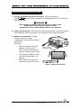
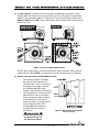
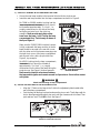
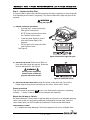
Lamp & Filter Replacement: INSTRUCTIONS
Introduction
These instructions explain how to replace the lamp module and air filter in all
Roadster, Vista and Mirage 4000/5000/6000 projectors. This 3-part procedure involves
replacing the old lamp module, recording the serial number of the new lamp module,
which resets the projector’s lamp timer, and replacing the air filter in the side of the
projector.
Make sure you have the correct Lamp & Filter Replacement Kit for your projector:
Table 1. Lamp & Filter Kits
Projector Model
Lamp & Filter Kit (new)
Lamp & Filter Kit (rebuilt)
700W models
Vista X3 / S3
03-000450-02P (reg.) or 03-000450-04P (HB)
03-000450R02P (reg.) or 03-000450R04P (HB)
Roadster X4 / S4
03-000450-02P (reg.) or 03-000450-04P (HB)
03-000450R02P (reg.) or 03-000450R04P (HB)
Mirage 4000
03-000450-04P
03-000450R04P
1200W models
Vista X5 / S5
03-000457-02P (reg.) or 03-000457-05P (HB)
03-000457R02P (reg.) or 03-000457R05P (HB)
Roadster X6 / S6
03-000457-02P (reg.) or 03-000457-05P (HB)
03-000457R02P (reg.) or 03-000457R05P (HB)
Mirage 5000 / 6000
03-000457-05P
03-000457R05P
03-000678-01P
Rebuilt lamp not yet available at time of printing
1800W models
Roadster X9 / S9
Note that rebuilt lamps include a previously installed lamp module in which the bulb
has been replaced, providing an economical equivalent to a new module. New and
rebuilt lamps carry the same warranty.
In most models, lamps should be replaced after 1000 hours of use or earlier (specific
warranties for each lamp model are published in a separate Lamp Program Document).
To determine the age of your current lamp, press Menu and go either to the Status or
Lamp menu. "Lamp Hours" indicates the total number of hours logged on the lamp.
Lamp & Filter Replacement Kit Components
- Lamp Module
- Side Filter
- Lamp Warranty Claim Form
- Instruction sheet
Tools Required
- 10” Phillips screwdriver
Warnings
Installation must be performed by qualified Christie projector
service personnel only.
Unplug the projector prior to servicing.
Observe electrostatic discharge precautions.
54-003646-06P (11/02)
1 of 9 Pages
Roadster • Vista • Mirage 4000/5000/6000 Lamp & Filter Instructions
Please read all instructions before you begin.
STEP 1 — Remove the old lamp
1) TURN OFF THE PROJECTOR AND ALLOW TO COOL. Turn off the projector
(press Power* OFF ) and wait for the cooling fans to automatically turn off. This will take
about five minutes.
WARNING
Never attempt to remove the lamp when it is hot. The lamp is under
high pressure when hot and may explode, causing
personal injury and/or property damage. Allow to cool completely.
2) UNPLUG THE PROJECTOR: When the cooling fans have turned off, unplug the projector.
Allow additional time for the lamp to cool completely. Never handle a hot lamp.
3) REMOVE LEFT SIDE GRILLE: The lamp
module is secured in a lamp
compartment near the left front corner of
the projector.
See Figure 1.
• Remove 5 screws securing the
projector’s left side panel.
NOTE: Some projectors do not
have the 2 bottom corner screws.
•
•
Lower the grille slightly to clear 2
pins at the bottom edge of the
projector.
Pull the grille off to expose the
lamp door near the front corner.
Figure 1. Remove left side grille
54-003646-06P (11/02)
2 of 9 Pages
Roadster • Vista • Mirage 4000/5000/6000 Lamp & Filter Instructions
4) REMOVE LAMP DOOR - For projectors manufactured before
October 1, 2000.
•
•
Remove the 2 top corner screws securing the lamp
door to the projector.
Lift the door slightly to free 2 bottom tabs, then
remove and set aside.
See Figure 2.
Figure 2. Remove
lamp door
(ORIGINAL STYLE)
OR…
OPEN LAMP DOOR
1, 2000.
•
•
- For projectors manufactured after October
Loosen the 2 bottom screws securing the lamp door
to the projector.
Swing the door up to open (it should stay up).
See Figure 3.
Not shown: Air deflector on underside of X9/S9 lamp
door. Do not remove.
Figure 3. Open Lamp
Door (NEW STYLE)
54-003646-06P (11/02)
3 of 9 Pages
Roadster • Vista • Mirage 4000/5000/6000 Lamp & Filter Instructions
5) LOOSEN T-BOLTS: The lamp module is secured to its adjustment plate with 3 large
spring-loaded T-bolts that lock in-and-out with a 90° turn (they are the largest heads
visible on the adjustment plate). To remove each T-bolt, use a Phillips screwdriver to
push and turn each bolt 90°. The pin behind each bolt will align with its slot and pop
the bolt free. See .
Figure 4. Loosen 3 spring-loaded T-bolts
NOTES: 1) In older models, if access to the bottom screw is blocked, reduce vertical
offset of the lens. 2) In X9/S9, you may want to remove the side-mount air deflector.
6) REMOVE LAMP AND DETACH FROM TERMINAL BLOCK
•
•
Pull the lamp module out slightly.
Note that it is still attached to a
“terminal block” which connects to
the lamp power supply via anode
and cathode cables—the lamp
module cannot be fully removed yet.
Turn the lamp over. At the top of the
terminal block, remove the single
screw securing the lamp module to
the terminal block. See Figure 5
(shows top view). The lamp should
now be fully free—refer to the
recycling/disposal instructions
provided at the end of these
instructions.
IMPORTANT
Detach the lamp from the
terminal block only. Do
not disconnect cables.
54-003646-06P (11/02)
4 of 9 Pages
Figure 5. Detach lamp from terminal
block (TOP VIEW)
Roadster • Vista • Mirage 4000/5000/6000 Lamp & Filter Instructions
7) ATTACH TO TERMINAL BLOCK AND INSERT NEW LAMP
•
Secure the new lamp module to the terminal block with the single screw.
•
Insert the new lamp module into the lamp compartment as shown in Figure 6.
For 700W or 1200W models: Looking into the
lamp compartment, the terminal block should
be located at approximately “3 o’clock”, i.e.,
roughly centered and on the side of the lamp
facing the projector front. See right, top
example. Make sure the main lamp cables
travel over the lamp, i.e. NOT along the lamp
compartment floor. Twist loosely as shown at
the top of Figure 6.
Make sure the 700W/1200W interlock harness
is fully underneath the lamp module. Its ferrite
bead should be secured in the rear left corner,
with the other end of the harness emerging near
the right front corner of the lamp compartment
and secured in the cable clip provided. See
Figure 6, top example.
For X9/S9: Looking into the lamp compartment,
the terminal block should be located at
approximately “9 o’clock”, i.e., roughly
centered and on the side of the lamp facing the
Figure 6. Lamp Orientation in
projector rear. See Figure 6, bottom example.
Different Models
Make sure the interlock wires travel between
the lamp and the igniter and remain secured in clip as shown. Do not allow contact
with igniter.
WARNING
Check lead dressing in lamp compartment!
8) SECURE THE NEW LAMP TO THE ADJUSTMENT PLATE
•
•
Align the 3 T-bolts on the lamp to the 3 slots in the adjustment plate located at the
rear of the lamp compartment.
Push the lamp all the way back and make sure the pin on each T-bolt aligns with its
slot on the alignment plate—slowly turn each until the clearance slot is located. Then
push and turn each T-bolt 90° to lock. See Figure 7.
Figure 7. Using the T-bolts
(INVERT ILLUSTRATION FOR X9/S9)
54-003646-06P (11/02)
5 of 9 Pages
Roadster • Vista • Mirage 4000/5000/6000 Lamp & Filter Instructions
•
Replace the side-mount air deflector if you had to remove it (X9/S9 only).
9) REPLACE / CLOSE THE LAMP DOOR
For original-style lamp door: At the lamp compartment opening, insert the tabbed
bottom edge of the door and swing the top edge into place. Secure the door with 2
screws.
For new-style lamp door: Swing the door back down to its original position and tighten
the 2 bottom screws.
10) REPLACE THE LEFT SIDE PANEL
Align the bottom of the left side panel with two pins at the bottom edge of the projector
and swing up into place. Secure with 5 screws (or 3, in early models).
NOTE: The lamp module is aligned and calibrated for maximum performance and
brightness in this projector. Do not attempt to re-align or adjust an installed lamp
module.
STEP 2 — Record the serial number & reset the Lamp Timer
POWER UP THE PROJECTOR AND RESET THE LAMP TIMER
Display the “Lamp” menu, and select the “Change Lamp” option—then enter the new
serial number in the S/N text box. When the new number is recorded, the lamp timer
will automatically reset to “0” hours and begin to log time.
IMPORTANT
If you neglect to enter a serial number, the lamp timer will not reset
to “0” and will therefore be inaccurate. The lamp life limit may then
expire prematurely.
If you record a serial number without having installed a new lamp,
the timer will still be reset and the lamp may expire without warning.
NOTES: 1) Once entered, the new lamp serial number is also automatically added to
the “Lamp History” submenu (read-only). 2) Lamp life data is required for warranty
claims.
54-003646-06P (11/02)
6 of 9 Pages
Roadster • Vista • Mirage 4000/5000/6000 Lamp & Filter Instructions
Step 3 — Replace the Side Filter
It is a good idea to replace the side filter whenever the lamp is replaced (or more frequently
if the operating environment is very dusty). This filter lies behind the right side grille of the
projector.
WARNING
Unplug the projector.
1) REMOVE THE RIGHT SIDE GRILLE:
•
Unscrew the 5 screws securing the
filter grill to the projector.
NOTE: Some projectors do not have
the 2 bottom corner screws.
•
Lower the panel slightly to clear 2
pins at the bottom edge of the
projector.
• Pull the grille off to expose the filter
near the front corner.
See Figure 8.
Figure 8. Remove the right side grille
2) REPLACE THE FILTER: Slide the used filter out
from under the top tab and replace. Make sure
the wire side faces IN. See Figure 9.
WARNING
Use only filters supplied by
Christie. Never operate the
projector without the air filter.
Figure 9. Install wire side IN
3) REPLACE THE RIGHT SIDE GRILLE: Align the bottom of the grille with 2 pins at the
bottom edge of the projector and swing up into place. Secure with 5 screws.
Power up and test
Plug in the projector and press Power* to turn it on. Make sure the projector is operating
normally – contact Christie if you run into problems and need help.
Return the old lamp to Christie
All lamps returned to Christie must be packed safely and securely in an adequate shipping
carton, such as the box and packing materials provided with the new lamp. Label the
carton clearly with your RMA number and returned to Christie as described below.
FOR WARRANTY CLAIMS:
1) Complete the Lamp Warranty Claim Form (supplied in this kit or available at the
54-003646-06P (11/02)
7 of 9 Pages
Roadster • Vista • Mirage 4000/5000/6000 Lamp & Filter Instructions
ERN website) and fax it to Christie for verification and assignment of an RMA
number.
2) Christie will fax your Lamp Warranty Claim Form back to you, along with the RMA
number required for shipments received at Christie.
3) Pack the lamp and your verified Lamp Warranty Claim Form in an adequate carton
(such as the box shipped with your new lamp). Make sure the lamp is packed
properly.
IMPORTANT
Improper packing of the lamp
voids any lamp warranty claim.
4) Clearly label your lamp carton with the RMA number provided and send the
package to your nearest Christie service depot (see below).
FOR NON-WARRANTY SHIPMENTS:
1) Contact Christie and request an RMA number.
2) Pack the lamp in an adequate carton (such as the box shipped with your new lamp).
Make sure the lamp is packed properly.
3) Clearly label your lamp carton with the RMA number provided and send the
package to your nearest Christie service depot (see below) for re-lamping. Label the
carton “freight collect” for free shipping.
NOTE: Your voluntary participation in this re-lamping program is strongly
encouraged, and helps ensure that Christie can continue to offer
economical replacement lamps with full warranty. Once you have returned
a used lamp, you are entitled to the purchase of a re-lamped lamp. Consult
the Lamp Warranty Program document for further re-lamping details.
54-003646-06P (11/02)
8 of 9 Pages
Roadster • Vista • Mirage 4000/5000/6000 Lamp & Filter Instructions
CHRISTIE Technical Support
NORTH AMERICA
CHRISTIE Digital Systems, Inc.
809 Wellington St. North
Kitchener, Ontario, Canada N2G 4Y7
Tel. 519-744-8005 (General)
Toll Free 1-800-221-8025 (Technical Support)
Fax 519-749-3302 (Service)
CHRISTIE Digital Systems, Inc.
10550 Camden Drive
Cypress, CA 90630
USA
Tel. 714-236-8610 (General)
Toll Free 1-800-221-8025 (Technical Support)
Fax 519-749-3302 (Service)
EUROPE
CHRISTIE Digital Systems, Inc.
View Point
200 Ashville Way
Wokingham, Berkshire RG41 2PL
United Kingdom
Tel. +44-118-977-8111
Fax +44-118-977-8112
CHRISTIE Digital Systems, Inc.
Hohenzollernstraße 124-126
41061 Mönchengladbach
Germany
Tel. +49-2161-664540
Fax +49-2161-664546
CHRISTIE Digital Systems, Inc.
7, av George Pompidou
92593 Levallois-Perret Cedex
France
Tel. +33-(0)1-47-48-28-07
Fax +33-(0)1-47-48-26-06
ASIA-PACIFIC / OTHER
CHRISTIE Digital Systems, Inc.
627A Aljunied Road
# 05-02 Biz Tech Centre
Singapore 389842
Tel. 65-6877-8737
Fax 65-6877-8747
CHRISTIE Sales (Canada)
Tel. 1-800-265-2171
Fax 519-749-3136
CHRISTIE Digital Systems, Inc.
Rm. C1109, Orient International Bldg. (Part C)
85 Lou Shan Guan Rd.
Shanghai, 200336
People’s Republic of China
Tel. +86-21-6278-7708
Fax +86-21-6278-7707
CHRISTIE Sales (U.S.)
Tel. 1-800-407-7727 or 1-800-333-3816
Fax 714-503-3375
Printed in Canada
54-003646-06P (11/02)
9 of 9 Pages


![CCM-LX [103-115108-01] QUICK SETUP GUIDE](http://vs1.manualzilla.com/store/data/005977333_1-ac67f3228bf0f13da08c247c088ce509-150x150.png)