1
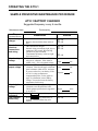
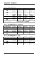
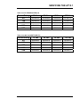
SERVICING THE AT10.1
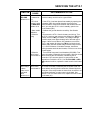
Error
Code
E 08
Meaning
Repair Procedure
defective
temperature
compensation
probe
(continued)
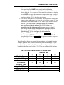
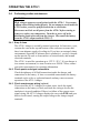
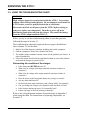
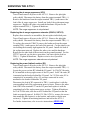
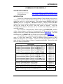
Disconnect the wiring from the probe, and measure the resistance of the
probe with an Ohmmeter. The resistance should be approximately 10,000
Ohms at normal room temperature (77° F / 25° C). If the probe reads
open or shorted, it needs to be replaced.
If the probe checks good, examine the wiring between the probe and the
AT10.1. Also check the connection of the cable to the control circuit board
on the back of the front panel. If the wiring is OK, then the probe needs to
be replaced. Once you have replaced the probe, you must restart the
AT10.1 to activate temperature compensation.
misadjusted
current limit
open internal
feedback loop
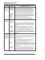
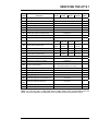
This code has been discontinued with main ctrl pcb (A1) firmware version
6.52. See Application Note (JD5035-00) for a description of this code.
E 11
E 12
not used
This error code is not implemented at this time.
defective
internal
thermostat
E 13
internal overtemperature
E 14
forced load
sharing not
working
properly
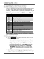
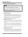
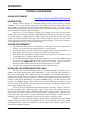
The AT10.1 rectifier heat sink assembly has beem equipped with a nonstandard over-temperature thermostat (S2). On startup, the AT10.1 tests
the thermostat, and displays E 12 if it is defective.
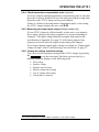
Check the thermostat (S2) for continuity. Disconnect the wiring and
resistor (R28) from the quick connect terminals. The thermostat switch
should be closed (NC) at normal room temperature.
The non-standard rectifier thermostat (S2) has detected an overtemperature condition. If the rectifier is equipped with a fan (B2), check
the fan for proper operation. Also make sure that all enclosure vents are
clear of debris, and that the ambient temperature is below 50°C (122°F).
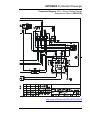
See Appendix F on page 90.
Verify both AT10.1s are functioning properly. Ensure that the forced load
sharing interconnection cable assembly is not broken, is properly installed,
and that the connector for the Secondary charger has the jumper as
described. Ensure that both AT10.1s are connected to the same ac
supply, and that source phase rotation is the same for both AT10.1s.
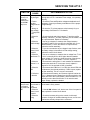
A 01
manual eqlz
enabled for
more than 24 hr
equalize mode
inhibited
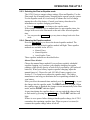
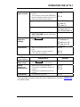
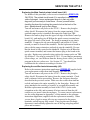
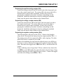
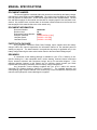
If the AT10.1 was accidentally left in manual equalize mode, switch the
unit back to float, manual equalize timer, or auto-equalize timer mode,
according to Section 2.2.4 on Page 27.
A 04
voltmeter
calibration
inhibited
w/tempco active
While using temperature compensation, the AT10.1 internal dc voltmeter
cannot be calibrated. Disconnect one wire of the tempco cable from TB8
on A1, and restart the AT10.1. Perform the voltmeter calibration according
to Section 2.3.7 on Page 37. Reconnect the tempco cable to TB8 and
restart the AT10.1. See Application Note (JD5003-00) for further details.
A 05
dc output at
Current Limit
setting
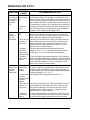
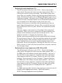
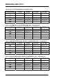
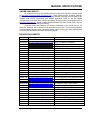
The AT10.1 is in Current Limit mode. This will occur when there is a large
load on the dc bus, or the battery has discharged. Make sure that the
AT10.1 is sized correctly for the application, and that the Current Limit
value has been set correctly. See Section 2.3.5 on Page 35.
E 09
E 10
A 02
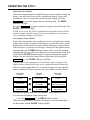
A redundant internal feedback loop (control loop) is provided as
redundancy, to increase reliability when remote sensing is used. If there is
a problem with the internal loop wiring, the AT10.1 will display E 10.
Check the internal wiring in the signal harness, especially wire # 33. Also
check the harness connector on the main control circuit board.
If you set the equalize timer to zero (0) hours, the equalize mode is
inhibited. When you try to put the AT10.1 into equalize mode from the
front panel controls, the display shows the message A 02. If you want to
enable the equalize mode, set the equalize timer to one (1) or more hours.
47