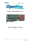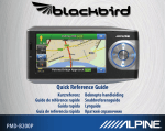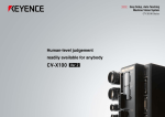
1
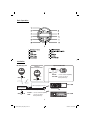
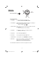
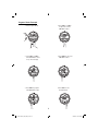
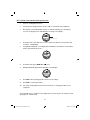
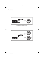
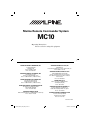
Marine Remote Commander System
MC10
• Operating Instructions
Please read before using this equipment.
ALPINE ELECTRONICS MARKETING, INC.
ALPINE ELECTRONICS OF U.K., LTD.
1-1-8 Nishi Gotanda
Shinagawa-ku
Tokyo 141-0031, Japan
Phone 03-5496-8231
ALPINE House
Fletchamstead Highway, Coventry CCV4 9TW, U.K.
Phone 0870-33 33 763
ALPINE ELECTRONICS FRANCE S.A.R.L.
ALPINE ELECTRONICS OF AMERICA, INC.
19145 Gramercy Place
Torrance, California 90501 U.S.A.
Phone 1-800-ALPINE-1 (1-800-257-4631)
(RCS PONTOISE B 338 101 280)
98, Rue de la Belle Etoile, Z.I. paris Nord II,
B.P. 50016, 95945 Roissy Charles de Gaulle
Cedex, France
Phone 01-48638989
ALPINE ELECTRONICS OF CANADA, INC.
777 Supertest Road Toronto
Ontario M3J 2M9, Canada
Phone 1-800-ALPINE-1 (1-800-257-4631)
ALPINE ITALIA S.p.A.
Viale C. Colombo 8, 20090 Trezzano
Sul Naviglio (MI), Italy
Phone 02-484781
ALPINE ELECTRONICS OF AUSTRALIA PTY, LTD.
161-165 Princess Highway, Hallam
Victoria 3803, Australia
Phone 03-8787-1200
ALPINE ELECTRONICS DE ESPAÑA, S.A.
Portal de Gamarra 36, Pabellón, 32
01013 Vitoria (Alava)-APDO 133, Spain
Phone 945-283588
ALPINE ELECTRONICS GmbH
Wilhelm-Wagenfeld-Str. 1-3 80807 München, Germany
Phone 089-32 42 640
ALPINE ELECTRONICS (BENELUX) GmbH
Leuvensesteenweg 510-B6,
1930 Zaventem, Belgium
Phone 02-725 1315
Printed in China
291031_MC10_OM_En_R1.indd 1
5/29/09 7:18:03 PM
Operating Instructions
WARNING
CAUTION
This symbol means important instructions.
Failure to heed them can result in injury or
material property damage.
WARNING
This symbol means important instructions.
Failure to heed them can result in serious injury
or death.
HALT USE IMMEDIATELY IF A PROBLEM
APPEARS.
Failure to do so may cause personal injury or
damage to the product. Return it to your authorized
Alpine dealer or the nearest Alpine Service Center
for replacing.
DO NOT OPERATE ANY FUNCTION THAT
TAKES YOUR ATTENTION AWAY FROM SAFELY
DRIVING YOUR BOAT.
Any function that requires your prolonged attention
should only be performed after coming to a
complete stop. Always stop the boat in a safe
location before performing these functions. Failure
to do so may result in an accident.
PRECAUTIONS
KEEP THE VOLUME AT LEVEL WHERE YOU
CAN STILL HEAR OUTSIDE NOISES WHILE
DRIVING.
Excessive volume levels that obscure sounds such
as emergency vessel sirens or approaching vessels
can be dangerous and may result in an accident.
LISTENING AT LOUD VOLUME LEVELS IN A BOAT
MAY ALSO CAUSE HEARING DAMAGE.
Product Cleaning
Use a soft dry cloth for periodic cleaning of the
product. For more severe stains, please dampen
the cloth with water only. Anything else has the
chance of dissolving the paint or damaging the
plastic.
Temperature
Be sure the temperature inside boat is between
+60°C (+140°F) and -10°C (+14°F) before turning
your unit on.
MINIMIZE DISPLAY VIEWING WHILE DRIVING.
Viewing the display may distract the driver from
looking ahead of the boat and cause an accident.
DO NOT DISASSEMBLE OR ALTER.
Doing so may result in an accident, fire or electric
shock.
Maintenance
If you have problems, do not attempt to repair the
unit yourself. Return it to your Alpine dealer or the
nearest Alpine Service Station for servicing.
DO NOT CONNECT A POWER SUPPLY OTHER
THAN A DC 12V NEGATIVE GROUND TYPE.
Failure to do so may result in accident or fire.
FCC COMPLIANCE STATEMENT
Operation is subject to the following two
conditions:
(1) This device may not cause harmful interference,
and
(2) This device must accept any interference
received, including interference that may cause
undesired operation.
KEEP SMALL OBJECTS SUCH AS BOLTS OR
SCREWS OUT OF THE REACH OF CHILDREN.
Swallowing them may result in serious injury. If
swallowed, consult a physician immediately.
USE THE CORRECT AMPERE RATING WHEN
REPLACING FUSES.
Failure to do so may result in fire or electric shock.
Changes or modifications not expressly approved
by the party responsible for compliance could void
the user’s authority to operate the equipment.
USE THIS PRODUCT FOR MOBILE 12V
APPLICATIONS.
Use for other than its designed application may
result in fire, electric shock or other injury.
2
291031_MC10_OM_En_R1.indd 2
5/29/09 7:18:04 PM
Basic Operation
Installation
MC10 Display Unit
Optional RUE-M1RF
Optional
Add-on Commander
333MHz
Wireless
GND
GND
MC1
+12V
GND
2.4GHz
Wireless
+12V
2.4GHz
Wireless
OR
To Steering Wheel Jack
+12V
IDA-X100M
To 10P Sub Display Connector
MC10
Transceiver Unit
GND
+12V
BLACK : connect to Ground (GND)
YELLOW : connect to 12V(+):
ACC (switched)
BLACK : connect to Ground (GND)
RED :
connect to 12V(+):
ACC (switched)
CDA-9886M
3
291031_MC10_OM_En_R1.indd 3
5/29/09 7:18:04 PM
Program Menu
MC10
Display unit
Enter Program Mode
Program Menu Options
1. ID NUMBER
This is the serial number of the display unit.
* Range of serial numbers: 00001 to 99999
2. RF STRENGTH
Signal strength between a display unit and the closest display or
transceiver unit in the MC10 wireless system
* Range of strength: [
]
to
3. SIGNAL STATUS
Wireless signal connection status between a display unit and the
transceiver unit
* Values: [CONNECTED, NO CONNECT]
4. CONTRAST
Sets brightness or dimness of LCD display characters
* Values: [5, 4, 3, 2, 1, 0]
5. BL DISPLAY
Turns LCD backlighting ON or OFF
6. BL KEYPAD
Turns keypad button backlighting ON or OFF
7. TEMPERATURE
Sets temperature scale to DEGREES F or DEGREES C
8. RESET MC1
Menu selection for pairing or re-pairing any MC1 or MC10
display units with any existing MC10 system.
RESET MC1 also restores factory default setting
* Note: Bold indicates default menu selection for this program menu option
4
291031_MC10_OM_En_R1.indd 4
5/29/09 7:18:10 PM
Program Mode Example
1. Enter Program Mode
4. Press VOL + or VOL –
to adjust the current
CONTRAST value
2. Press VOL + or VOL –
until CONTRAST shows
on top line of display
5. Press ENT to save new
CONTRAST value
3. Press ENT to program
new CONTRAST value
6. Press ESC to exit
Program Mode
5
291031_MC10_OM_En_R1.indd 5
5/29/09 7:18:10 PM
MC1 Add-on Commander Pairing Procedure
1.
Power on existing MC10 system
2.
Connect power and ground wires of MC1 add-on commander (see Installation)
3.
MC1 add-on commander display will turn on and automatically go to the pairing
screen in the program menu with ADD MC1 showing on the display
ADD MC1
MC1 Paring Screen
4.
On marine radio, select FM Tuner as source (make sure that tuner seek mode is DX
or LOCAL , not MANUAL)
5.
Found Radio will appear on the display below ADD MC1 when add-on commander is
ready to pair with MC10 system *
ADD MC1
Found Radio
6.
On marine radio, press SEEK UP (
) once
7.
PRESS ENTER will appear below ADD MC1 on the display
ADD MC1
PRESS ENTER
8.
Press ENT to finish pairing operation and save new settings
9.
Press ESC to exit Program Menu
10.
Turn off the existing MC10 system, then turn it back on. Pairing procedure is now
completed.
*If Found Radio does not appear on the display, MC1 location may be out of MC10 system
range (typical ~ 40 feet/12 m)
6
291031_MC10_OM_En_R1.indd 6
5/29/09 7:18:11 PM
Example Systems
Transceiver
2.4GHz
Wireless
APN Marine Head Unit
MC10 Marine Commander System
Transceiver
2.4GHz
Wireless
2.4GHz
Wireless
MC1
Add on
APN Marine Head Unit
MC10 Marine Commander System with MC1 Add on Commander
7
291031_MC10_OM_En_R1.indd 7
5/29/09 7:18:11 PM
MC10 Display Unit Re-Pairing Procedure
* To pair an MC10 display unit with a different MC10 system than the one it was
purchased with (just like adding an MC1 Commander) follow the instructions
below:
1. Power on the MC10 system that you want to add the additional MC10
display unit to
2. Connect power and ground wires of new MC10 display unit
3. Wait at least 20 seconds, then enter the Program Menu (see Program
Menu Example)
4. Go to the RESET MC1 option, then press ENT button
5. MC10 display unit will reset itself (including factory default settings) and
display will show ADD MC1 like in step 3 of the previous section (MC1
Add-on Commander Pairing Procedure)
6. Follow the remaining steps of the previous section to complete this
operation
8
291031_MC10_OM_En_R1.indd 8
5/29/09 7:18:12 PM