1
AT&T
AT&T System 25
Installation and
Maintenance Manual
555-540-103 B
November 1995
©1989 AT&T
All Rights Reserved
Printed in USA
TO ORDER COPIES OF THIS DOCUMENT REFER TO DOCUMENT NUMBER
555-540-103
Contact: Your AT&T sales representative, or
Call: 800-432-6600, Monday through Friday between 7:30 am
and 6:00 pm EST, or
In Canada call: 800-255-1242
Write: AT&T Customer Information Center
2855 North Franklin Road
P.O. Box 19901
Indianapolis, Indiana 42619
Every effort was made to ensure that the information in this document was
complete and accurate at the time of printing. However, this information is
subject to change. This document will be reissued periodically to incorporate
changes.
Installation and Maintenance Manual
Prepared by System 25
Document Development Group and the
AT&T Documentation
Management Organization
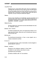
DANGER
Do not open the fan assembly or remove rear cabinet cover before
unplugging the cabinet from the electrical outlet. Wait at least five
minutes after unplugging the power cord before removing the rear
cover or power supply. The AT&T System 25 cabinets are not user
serviceable. Some voltages inside the cabinets are hazardous.
This equipment is to be serviced only by qualified technicians.
CUSTOMER WARNING
The Installation and Maintenance Manual is designed for use b y
qualified service technicians only. Technician qualification includes
completion of an AT&T hands-on instructor-led course covering
installation and maintenance for this product. The use of these
documents by anyone else might void the warranty. Hazardous
electrical voltages are present inside this product.
SERVICE TECHNICIAN WARNING
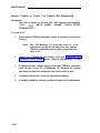
1. Never install telephone wiring during a lightning storm.
2. Never install telephone jacks in wet locations unless the j a c k
is specifically designed for wet locations.
3. Never touch uninsulated telephone wires or terminals unless the
telephone line has been disconnected at the network interface.
4. Use caution when installing or modifying telephone lines.
a
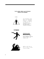
THE FOLLOWING SYMBOLS AND PICTOGRAPHS
APPEAR ON THE EQUIPMENT
SYMBOL
The exclamation point
within an equilateral
triangle is intended
to alert the user to
the presence of
important operating
and maintenance
(servicing) instructions
ELECTRICAL SHOCK
Warns of the danger
of electrical shock
from hazardous voltages
present within the
control unit
Warns of the risk of
fire if the air filter
is not in place
b
FCC NOTIFICATION AND REPAIR INFORMATION
AT&T SYSTEM 25
This telephone equipment is registered with the Federal Communications
Commission (FCC) in accordance with Part 68 of its Rules. In compliance with
the Rules, be advised of the following:
MEANS OF CONNECTION
Connection of this telephone equipment to the nationwide telecommunications
network shall be through a standard network interface USOC RJ21X jack.
Connection to private line network channels requires USOC RJ2GX jack for tie
lines or USOC RJ21X jack for off-premises station lines. Connection to T1
facilities requires USOC RJ48X or RJ48C jack. These can be ordered from your
telephone company.
NOTIFICATION TO THE TELEPHONE COMPANY
If the system is to be connected to off-premises stations (OPSs), you must notify
the telephone company of the OPS class of service, OL13C, and the service
order code, 9. OF. For R3 systems, the Analog service order code is 9.0Y, the
Digital service order code is 6.0Y.
Upon the request of the telephone company, inform them of the following:
— The Public Switched Network “lines” and the Private “lines” to which
you will connect the telephone equipment.
— For private line connections, provide the facility interface code, TL31M
for tie lines. You must also specify the service order code, 9.0F or 9.0Y
for R3 systems.
Customer instructions will advise the customer to provide the telephone
company with the registration number (either -MF or -KF, depending on
the application of the system) and the ringer equivalency number (REN)
from the label on the equipment. In addition, customer will be advised
c
that certification in writing may be required when an existing
multifunction system is being reconfigured as a Key system, if the
customer desires the lower rate.
— For Digital connections with D4 Framing Format provide the Facility
interface code 041DU9-B, for digital connections with Extended Framing
Format, provide the Facility interface code 04DU9-C. You must also
specify the service order code, 6.0Y.
— The quantities and USOC numbers of the jacks required.
— For each jack, provide the sequence in which lines are to be connected;
the type lines and the facility interface code and the ringer equivalence
number by position, when applicable.
This telephone equipment should not be used on coin telephone lines.
Connection to party line service is subject to state tariffs.
REPAIR INSTRUCTIONS
If you experience trouble with this telephone equipment, contact the AT&T
Business Customer Service Center on 1-800-242-2121. The telephone company
may ask that you disconnect this equipment from the network until the problem
has been corrected or until you are sure that this equipment is not
malfunctioning.
System 25 troubles that must be escalated to a higher level of maintenance
should be referred to the National Service Assistance Center on 1-800-628-2888.
RIGHTS OF THE TELEPHONE COMPANY
If your telephone equipment causes harm to the telephone network, the
telephone company may discontinue your service temporarily. If possible, they
will notify you in advance. But if advance notice isn’t practical, you will be notified
as soon as possible. You will be informed of your right to file a complaint with the
FCC.
d
Your telephone company may make changes in its facilities, equipment,
operations, or procedures that could affect the proper functioning of your
equipment. If they do, you will be notified in advance to give you an opportunity
to maintain uninterrupted telephone service.
HEARING AID COMPATIBILITY
The voice terminals described in this manual are compatible with inductively
coupled hearing aids as prescribed by the FCC.
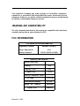
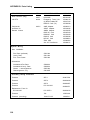
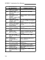
FCC INFORMATION
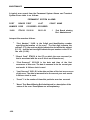
FCC REGISTRATlON lNFORMATlON
Registration Number
AS593M-71565-MF-E
Ringer Equivalence
0.5A
Network Interface
RJ21X, RJ2GX or RJ48X
PRIVATE LINE SERVICE
Service Order Code
9.0F
●
Analog
●
Analog (R3)
●
Digital (R3)
9.0Y
I
6.0Y
Facility Interface Code
●
●
●
Off-Premises Stations
OL13C
Digital
04DU9-B
●
November 1995
TL31 M
Tie Lines
D4
Framing
Digital ESF
04DU9-C
FCC WARNING STATEMENT
Federal Communicatlons Commission (FCC) Rules require that you be notified of
the following:
This equipment generates, uses, and can radiate radio frequency energy and, if
not installed and used in accordance with the instruction manual, may cause
interference to radio communications.
It has been tested and found to comply with the limits for a Class A computing
device pursuant to Subpart J of Part 15 of FCC Rules, which are designed to
provide reasonable protection against such interference when operated in a
commercial environment.
Operation of this equipment in a residential area is likely to cause interference
in which case the user at his or her own expense will be required to take
whatever measures may be required to correct the interference.
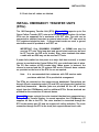
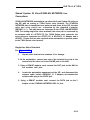
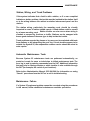
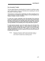
SECURITY OF YOUR SYSTEM-PREVENTING TOLL FRAUD
As a customer of a new telephone system, you should be aware that there exists
an increasing problem of telephone toll fraud. Telephone toll fraud can occur in
many forms, despite the numerous efforts of telephone companies and telephone
equipment manufacturers to control it. Some individuals use electronic devices
to prevent or falsify records of these calls. Others charge calls to someone else’s
number by illegally using lost or stolen calling cards, billing incorrect parties,
clipping on to someone else’s line, and breaking into someone else’s telephone
equipment physically or electronically. In certain instances, unauthorized
individuals make connections to the telephone network through the use of remote
access features.
The Remote Access feature of your system, if you chose to utilize it, permits offpremises callers to access the system from a remote telephone by using an 800
number or a 7- or 10- digit telephone number. The system returns an
acknowledgement signaling the user to key in his or her authorization code,
which is selected and administered by the system manager. After the
authorization code is accepted, the system returns dial tone to the user. If you do
not program specific egress restrictions, the user will be able to place any call
normally dialed from a telephone associated with the system. Such an offpremises network call is originated at, and will be billed from, the system location.
The Remote Access feature, as designed, helps the customer, through proper
administration, to minimize the ability of unauthorized persons to gain access to
the network. Most commonly, phone numbers and codes are compromised
when overheard in a public location, through theft of a wallet or purse containing
access information, or through carelessness (writing codes on a piece of paper
and improperly discarding it). Additionally, hackers may use a computer to “dial”
an access code and then publish the information to other hackers. Enormous
charges can be run up quickly. It is the customer’s responsibility to take the
appropriate steps to properly implement the features, evaluate and administer the
various restriction levels, protect access codes, and distribute access codes only
to individuals who have been fully advised of the sensitive nature of the access
information.
Common carriers are required by law to collect their tariffed charges. While
these charges are fraudulent charges made by persons with criminal intent,
applicable tariffs state that the customer of record is responsible for payment of
all long-distance or other network charges. AT&T cannot be responsible for such
charges and will not make any allowance or give any credit for charges that result
from unauthorized access.
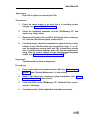
To minimize the risk of unauthorized access to your communications system:
●
●
●
●
●
●
Use a nonpublished Remote Access number.
Assign authorization codes randomly to users on a “need-to-have”
basis, keeping a log of ALL authorized users and assigning one code
per person.
Use random sequence authorization codes, which are less likely to be
broken.
Deactivate all unassigned codes promptly.
Ensure that Remote Access users are aware of their responsibility to
keep the telephone numbers and any authorization codes secure.
When possible, restrict the off-network capability of off-premises callers,
via use of Call Restrictions and Disallowed List capabilities.
●
●
●
When possible, block out-of-hours calling.
Frequently monitor system call detail reports for quicker detection of any
unauthorized or abnormal calling patterns.
Limit Remote Call Forward to persons on a “need-to-know” basis.
Contents
INTRODUCTION
FCC PRECAUTIONS
INSTALLATION
1-1
1-2
2-1
TOOLS AND TEST EQUIPMENT
2-2
CROSS-CONNECT EQUIPMENT DESCRIPTION
Trunk Access Equipment
2-3
2-4
2-4
2-4
2-6
2-6
2-8
2-10
2-11
2-11
2-12
2-12
2-12
2-13
2-15
700A-110-BI -25 or 700A-66-B1-25 Cut-Down Jack
108 Emergency Transfer Unit (ETU)
Station Interconnect Panel (SIP)
617A Panel
Adapters
Fanning Strip
Cables
Splitter Cables
Octopus Cables
853B Adapter Cable
DS1 Connector Cables
Cable Labels
Symbols Used in Figures
PREINSTALLATION REQUIREMENTS
Table and Backboard
Network Interface
AC Power
Grounding
Lightning Protection
Secondary Protection
Building Wiring
2-16
2-16
2-16
2-18
2-18
2-19
2-21
2-22
INSTALL SYSTEM CABINETS
Position Cabinet(s)
Check Cabinet Contents
Required Circuit Pack Positions
Label Connectors on Back Cover
Install 4A Retainer Clips
Connect Cabinet
2-23
2-23
2-23
2-28
2-28
2-29
2-30
TDM Bus Connections.
Ground Wire Connections.
2-30
2-33
POWER UP AND INITIALIZE SYSTEM
Connect Power
Connect Administration Equipment
Cold Start the System
Check Performance of Cabinet Components
Report Problems
Initialize System
2-33
2-33
2-34
2-35
2-39
2-42
2-43
INSTALL CROSS-CONNECT EQUIPMENT
Install TAE, 617A Panels, and Fanning Strips
Mount 858A orZ210A2 Adapters
2-43
2-44
2-47
INSTALL MODULAR BULK POWER SUPPLY
(Optional)
2-49
INSTALL EQUIPMENT ROOM TRUNK CABLING
Connect Network Interfaces to TAE Blocks
Connect Cabinets to TAE Blocks
Connect Ground Start, Loop Start, and DID Trunks
Connect Tie Trunks
Install DS1
Connect S25 to Another On Premises PBX
Off Premises Metallic (Cable) Connections
Off Premises Non Metallic Connections
Install Customer Service Unit (CSU)
Line Compensation/Equalization
Connect Coupled Bonding Conductor (CBC)
INSTALL EQUIPMENT ROOM STATION CABLING
Connect Building Wiring to SIP
Modular Plug Termination
4-Pair Cable Terminations
Connect Cabinets to SIP
Prepare Carrier Loading Labels
Modify Octopus Cables if Required
Make SIP Connection for CPU/Memory
Make SIP Connections to Cabinet for 7300H Series
Terminals
Make SIP Connections to Cabinet for MET Sets
Make SIP Connections to Cabinet for Single-Line Sets
-ii-
2-49
2-49
2-51
2-51
2-52
2-53
2-53
2-56
2-56
2-57
2-58
2-58
2-60
2-62
2-62
2-64
2-66
2-67
2-69
2-71
2-73
2-74
2-74
Make SIP Connections for Data Terminals and
Computers
Make SIP Connections to Cabinet for ATL Cordless
Telephones
Perform SIP Housekeeping
2-75
2-76
2-76
INSTALL EMERGENCY TRANSFER UNITS (ETUs)
Make Emergency Transfer Connections
Install Ground-Start Key
2-77
2-80
2-82
INSTALL ATTENDANT CONSOLE
2-83
INSTALL TERMINALS
2-87
2-88
2-90
2-91
Label Terminals
Stand-Alone Voice Terminals
Stand-Alone Remotely Powered Voice Terminals
Single-Line and 7300H Series Voice Terminals With
Associated ADUs
ATL Cordless Telephone
Off-Premises Stations (TN742)
Out-of-Building Voice Terminals (TN742)
Out-of-Building Voice Terminals (ZTN79)
Off-Premises— D S 1 l n t e r f a c e
Stand-Alone Data Terminals
ADU Connections
MADU Connections
2-92
2-94
2-95
2-95
2-96
2-96
2-98
2-98
2-101
INSTALL CUSTOMER’S S A T
Nonswitched Connection of Equipment Plugged Into
System AC Outlet
Nonswitched Connection of Equipment
On-Premises Digital Switched Connection
Off-Premises Nonswitched Connection
Off-Premises Switched Connection
2-102
INSTALL CUSTOMER’S DTU
2-111
2-102
2-104
2-106
2-109
2-109
INSTALL STATION MESSAGE DIGITAL RECORDING
(SMDR) EQUIPMENT
INSTALL STARLAN NETWORK INTERFACE
Shared System 25 Voice/STARLAN NETWORK Data
Connections
Single-Line Voice Terminals
2-111
2-112
2-113
2-113
-III-
7300H Series Voice Terminals
INSTALL MUSIC-ON-HOLD INTERFACE
FCC-Registered Music Source Interface
Non-FCC Registered Music Source Interface
INSTALL EXTERNAL ALERTS
INSTALL RECORDED DELAY ANNOUNCEMENT
2-117
2-117
2-119
2-120
2-121
INSTALL DICTATlON SYSTEM INTERFACE
2-121
INSTALL PAGING SYSTEM INTERFACE
2-121
2-122
Direct Connection to TN763 Auxiliary Trunk CP
Connection to TN763 Auxiliary Trunk CP (278A
Adapter Required)
Connection to ZTN76 or ZTN77 CP
SYSTEM TESTS
-iv-
2-115
2-124
2-128
3-1
TEST OUTGOING TRUNKS
3-1
TEST DS1 INTERFACE.
3-1
TEST INCOMING DID TRUNKS
3-2
TEST INCOMING TIE TRUNKS
3-2
TEST 7300H SERIES VOICE TERMINALS
3-3
TEST SINGLE-LINE VOICE TERMINALS
3-5
TEST ATL CORDLESS TELEPHONE
3-6
TEST DIAL ACCESS CODES
3-6
TEST SYSTEM FEATURES
ARS and SMDR Tests
DGC Test
System Speed Dialing Test
PDC Login Test
Call Coverage Test
3-6
3-6
3-7
3-7
3-8
3-8
TEST ATTENDANT CONSOLE
3-9
TEST SELECTOR CONSOLE
3-9
TEST DATA TERMINAL DIALING FEATURE
3-10
MAKE POOLED MODEM TEST CALL
....
TEST TRANSFER TO DATA
TEST EXTERNAL ALERT (NIGHT SERVICE)
TEST DICTATION SYSTEM ACCESS
. . . . ... . . .
3-11
3-11
3-12
TEST PAGING INTERFACE
3-13
3-13
TEST MUSIC-ON HOLD
3-14
TEST EMERGENCY TRANSFER
3-15
TEST TOUCH-TONE RECEIVERS
3-16
MAINTENANCE
4-1
EQUIPMENT NEEDED
Precautions
GENERAL INFORMATION
System Errors and Alarms
Emergency Transfer
Circuit Pack LEDs
Attendant Console LED
Power Supply
Switches and Test Points
System Administration
Remote Initialization Maintenance (RIM) Service
4-4
4-4
4-4
4-4
4-6
4-6
4-6
4-6
4-6
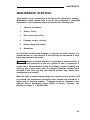
MAINTENANCE STRATEGY
Total System Failures
Port Problems
Common Control Problems
Staion, Trunk Problems
Antomatic Maintenance Tests
Maintenance Failure
4-9
4-11
4-11
4-12
4-13
4-13
4-13
USING THE DIGITAL TAPE UNIT
Setting Up the DTU
Saving Translations
Verifying Translations
Restoring Translations
4-14
4-14
4-15
4-16
4-18
-v-
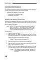
ROUTINE MAINTENANCE
Reseating and Replacing Circuit Packs
Removing and Restoring Power
Restarting the System
4-20
4-20
4-22
4-23
ERROR LOG
Accessing the Error Log From the SAT
4-27
4-30
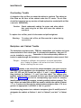
ERROR MESSAGES
Clearing System-Detected Troubles
Complete System Failure
Common Control Trouble
Circuit Pack Trouble
Frontplane Ribbon Connector Trouble (Release 1
Only)
Power Supply Trouble
Power Supply Protection
Power Supply Replacement
Fan Assembly Trouble
Overheating Trouble
Backplane and Cabinet Trouble
Emergency Transfer Unit Trouble
4-32
4-61
4-61
4-61
4-63
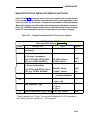
Special Port Circuit Options for Stations and Trunks
Data Line Troubles
4-81
4-81
4-82
4-82
4-83
4-84
4-85
4-89
4-89
4-90
4-90
4-91
4-92
4-93
4-99
4-100
Multiple Troubles or Trouble That Cannot Be
Diagnosed
4-102
CLEARING USER-DETECTED TROUBLES
Administration Equipment Troubles
Time-Keeping Troubles
Voice Terminal and Wiring Troubles
Voice Transmission Troubles
7300H Series Terminal Troubles
Virtual Facilities Troubles
Trunk Troubles
Outgoing Trunk Problems
Incoming Trunk Problems
Error Log Interpretation: Loop-Start Trunks
Error Log Interpretation: Ground-Start Trunks
DID Trunks Troubles
Switched Loop Attendant Console Troubles
-vi-
4-64
4-64
4-69
4-70
4-71
4-72
4-72
4-80
REFERENCES
5-1
ABBREVIATIONS AND ACRONYMS
6-1
APPENDIX A: System Wiring T a b l e s
A-1
Connector Pin Assignments
A-1
System 25 Building Wiring
A-1
APPENDIX B: Parts Listing
B-1
APPENDIX C: System Additions or Changes
C-1
Evaluate Cabinet Unit Power Load
C-1
Add Circuit Pack
Add Cabling
Set Option Switches on TN760B CP
C-2
C-3
C-5
Replace Circuit Pack
C-7
Add Cabinet
C-8
Add Termina
C-10
Add Trunk
C-11
Add Trunk—DSl Interface
C-11
Replace Voice-Only Terminal With Voice/Data
Terminal
C-12
Add Pooled Modem Circuit Pack
C-13
Add Auxiliary Equipment
C-13
APPENDIX D: System Upgrades
D-1
APPENDIX E: Administration Codes and Data
E-1
E-1
Default Dial Code Assignments
-vii-
APPENDIX F: Administration Error Messages
F-1
GLOSSARY
G-1
INDEX
I-1
-viii-
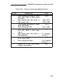
Figures
Figure
Figure
Figure
Figure
Figure
Figure
Figure
Figure
Figure
Figure
Figure
2-1.
2-2.
2-3.
2-4.
2-5.
2-6.
2-6a.
2-7.
2-8.
2-9.
2-10.
Figure 2-11.
Figure 2-12.
Figure 2-13.
Figure
Figure
Figure
Figure
Figure
Figure
Figure
Figure
Figure
Figure
Figure
Figure
Figure
2-14.
2-15.
2-16.
2-17.
2-18.
2-19.
2-20.
2-21.
2-22.
2-23.
2-24.
2-25.
2-26.
Figure
Figure
Figure
Figure
Figure
Figure
Figure
Figure
Figure
Figure
2-27.
2-28.
2-29.
2-30.
2-31.
2-32.
2-33.
2-34.
2-35.
2-36.
November 1995
10 BEAU
617A Panel
SIP Adapters
50A Fanning Strip
Splitter Cables
Octopus Cable
853B Adapter Cable
Cable Labels
Typical System 25 Floor Plan
AC Power Distribution—Multiple Cabinet System
Three-Cabinet System, Front View With Covers
Removed
Position of Shorting Plugs on CPU/Memory Circuit
Pack . . . . . . . .
4A Retainer Clip Installation
TDM Bus Terminations (Rear View of 3-Cabinet
System)
Temporary SAT and DTU Connections
Typical System 25 Port Circuit Pack
SIP and TAE Backboard Layout
Alternate SIP and TAE Backboard Layout
Mounting Adapters
Direct Connection (Side by Side)
Direction Connection (Side by Side)
DS1 Connections—1311 to 4310 Feet
DS1 mnnections4311 Feet or More
DS1 Connections–Off Premise Cabling
DS1 Connections-Non Metallic Connections
CSU Connections
Voice and Data Station Records Form (Example
Entered)
Modular Plug Terminations Connected to the SIP
Cut Down Terminations Connected to the SIP
Carrier Loading Label
Standard and Modified Octopus Cables
Mounting Octopus Cable on Fanning Strip
10B Emergency Transfer Unit
Emergency Transfer Unit Connections
Ground Start Key Installation
Attendant Console With DXS Console
Remotely Powered DXS Console Connection
2-5
2-7
2-9
2-10
2-11
2-12
2-12
2-14
2-17
2-21
2-26
2-27
2-29
2-32
2-34
2-42
2-45
2-46
2-48
2-54
2-54
2-55
2-55
2-56
2-57
2-58
2-61
2-63
2-65
2-68
2-70
2-72
2-78
2-79
2-82
2-84
2-86
-ix-
Figure 2-37.
Figure 2-38.
Figure
Figure
Figure
Figure
Figure
Figure
Figure
2-39.
2-40.
2-41.
2-42.
2-43.
2-44.
2-45.
Stand-Alone Voice Terminal Connections
2-90
Stand-Alone Remotely Powered Voice Terminal
Connections
2-91
Single-Line Terminal/ADU Connections
2-93
7300H Series Terminal/ADU Connections
2-94
DS1 to D4 Connections for Off-Premises Stations 2-97
Local Powering of an ADU
2-99
Remote Powering of an ADU (Optional)
2-100
MADU to Host Computer or Terminals Connections 2-101
Nonswitched Connection of Peripheral Equipment
Plugged Into System AC Outlet
2-103
Figure 2-46.
Figure 2-47.
Figure 2-48.
Figure 2-49.
Figure 2-50.
Figure 2-51.
Figure 2-52.
Figure 2-53.
Figure 2-53a.
Figure 2-54.
Figure 2-55.
Figure 2-55a.
Figure 2-56.
Figure 2-57.
Figure 2-58.
Figure
Figure
Figure
Figure
Figure
Figure
Figure
Figure
-x-
2-59.
4-1.
4-2.
4-3.
4-4.
4-5.
4-6.
4-7.
Greater Than 50 Feet and/or Not Sharing Same
2-105
AC Outlet
On-Premises Peripheral Equipment With Switched
Connection to CPU/Memory
2-108
Off-Premises Peripheral Equipment With Direct
2-110
Connection to CPU/Memory
ZTN84 STARLAN Interface CP Connection
2-112
Single-Line Analog Terminal/STARLAN
NETWORK Workstation Connections
2-114
7300H Series Terminal/STARLAN NETWORK
Workstation Connections
2-116
Music Source, FCC Registered
2-118
2-119
Music Source, Non-FCC Registered
Music-on-Hold
2-119a
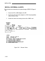
External Alerts
2-120
Paging System Connection to TN763 Circuit Pack 2-123
Loudspeaker Paging with Background
Music
2-124a
Paging System Connection to TN763 Circuit Pack
2-126
(278A Adapter Required)
278A Adapter Plug Positions for Connecting TN763
2-127
Circuit Pack to Paging System
PagePac 20 System Connection to ZTN76 or
2-129
ZTN77 Circuit Pack
Paging System Connection to ZTN76 or ZTN77 2-131
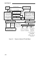
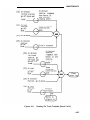
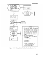
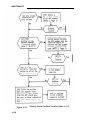
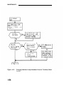
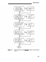
Response to System 25 Trouble Report
4-10
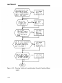
Clearing Power Supply Troubles (Sheet 1 of 4-47
Clearing CO Trunk Troubles
4-49
Clearing 4-Wire Tie Trunk Troubles (Sheet 1 of 4)
4-50
Clearing STARLAN Interface Troubles
4-54
Clearing Tie Trunk Troubles (Sheet 1 of 5) 4-55
Clearing Paging Equipment Troubles
4-60
November 1995
Figure 4-8.
Figure 4-9.
Figure 4-10.
Figure 4-11.
Figure 4-11.a.
Figure 4-12.
Figure 4-13.
Figure C-1.
Figure C-2.
Figure C-3.
AC Power Schematic
4-68
System Cabinet Backplane Wiring Side (Sheet 1
of 2)
4-73
TDM Signal Destinations on Cabinet Backplane
4-75
Power Designations on Cabinet Backplane
4-76
853 Adapter
4-79a
Clearing Virtual Facilities Troubles (Sheet 1 of 3) 4-86
Clearing Switched Loop Attendant Console
Troubles (Sheet 1 of 5)
4-94
Typical System 25 Port Circuit Pack
C-4
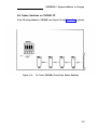
Tie Trunk (TN760B) Circuit Pack Option Switches C-5
DS1 Network Interface Connections
C-12
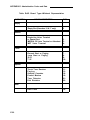
Tables
Table 2-A.
Table 2-B.
Table 2-C.
Table
Table
Table
Table
2-D.
2-E.
2-F.
4-A.
Table
Table
Table
Table
Table
4-B.
4-C.
4-D.
4-E.
4-F.
Table A-A.
Table A-B.
Table A-A.
Table A-B.
Table C-A.
Table C-B.
Table E-A.
Table E-B.
November 1995
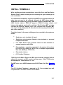
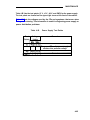
Tools and Test Equipment Required for
Installation
Circuit Packs, Their Functions, and Protectors
Displayed SAT Messages During Cold or Warm
Restart
Circuit Pack LED Status Indications
Circuit Pack Versus Terminal Type
Feature Button Abbreviations and Lables
Displayed SAT Messages During Cold or Warm
Start
Power Supply Test Points
Circuit Pack Voltages—Symptoms
25-Pair Connector to Backplane Designations
Station/Trunk/Special Port Circuit Pack Options
Applicable Actions for Circuit Pack Options
100
25-Pair Connector Pin Assignments
Building Wiring
25-Pair Connector Pin Assignments
Building Wiring
Unit Loads
TN760B Option Switch Settings and
Administration
Default Dial Codes
PORT/PD. Administration, Voice Terminals
(Menu=1/2)
2-2
2-24
2-37
2-40
2-66
2-88
4-25
4-65
4-66
4-78
4-99
4A-2
A - 4
A-2
A-4
C-2
-xi-
C-6
E-1
E-2
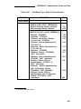
Table
Table
Table
Table
E-C.
E-D.
E-E.
E-F.
Table E-G.
..
Table E-H.
Table E-1.
Table E-J.
Table E-K.
Table
Table
Table
Table
Table
Table
Table
Table
Table
Table
Table
Table
Table
E-L.
E-M.
E-N.
E-0.
E-P.
E-Q.
E-R.
E-S.
E-T.
E-U.
E-V.
E-W.
E-X.
Table E-Y.
Table E-Z.
Table E-AA.
Table
Table
Table
Table
Table
Table
Table
-xii-
E-AB.
E-AC.
E-AD.
E-AE.
E-AF.
E-AG.
E-AH.
Voice Terminal Type Codes
Feature Button Translation (Menu=1/2)
Multiline Voice Terminal Button Defaults
Switched Loop Attendant Console Button
Defaults (Type 310)
Switched Loop Attendant Console Button
Defaults (Type 311)
Direct Trunk Attendant Console Button Defaults
(Cold-Start Defaults)
Direct Trunk Attendant Console Defaults
(Administration-lnstalled Defaults)
MET Set Button Defaults
PORT/PDC Administration, Data Terminals
(Menu=1/2)
Data Port Type Codes
Port Administration, Trunks (Menu=1)
Trunk Type Codes
Trunk Class-of-Service (for all trunks except DID)
Port Administration, Auxiliary Equipment
(Menu=1)
Special Feature Port Type Codes
Port Options
Applicable Options
PDC Administration (Menu=2)
High Density Circuit (Menu=3)
System Administration (Menu=4)
Standard Call Type Defaults
Message-Center-Like Call-Type Defaults (effect
of Action 90)
Floating PDC Administration (Menu=5)
Direct Group Calling (DGC) Administration
(Menu= 6)
Toll Calls Allowed (TCA) List Administration
(Menu= 7)
DGC Announcement Administration
Searches: Action Items (Menu=8)
Board Type—Wildcard Representation
Port/Board Type—Specific Representation
Save/Restore and System Restarts (Menu=9)
RS232 Port Administration (Menu=10)
Automatic Route Selection Administration
(Menu=11)
E-13
E-14
E-17
E-18
E-19
E-20
E-21
E-22
E-23
E-25
E-26
E-28
E-29
E-30
E-32
E-33
E-34
E-35
E-35
E-36
E-42
E-43
E-43
E-44
E-44
E-45
E-46
E-50
E-51
E-54
E-55
E-56
November 1995
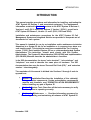
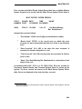
INTRODUCTION
INTRODUCTION
This manual provides procedures and information for installing, and testing the
AT&T System 25 Release 3 and associated equipment. The maintenance
information contained in Section 4 pertains to the AT&T System 25 Release 1,
Versions 1 and 2 (RI VI and R1V2), Release 2, Version 1 (R2V1 ), as well as to
AT&T System 25 Release 3, Version 1,2 and 3 (R3V1, R3V2 and R3V3).
Installation and maintenance procedures for the AT&T System 25 Call
Management System and Integrated Solution are provided in a separate set of
documents for each system.
This manual is intended for use by an installation and/or maintenance technician
dispatched to a System 25 site for an installation or in response to an alarm or a
user trouble report. This technician must have completed the Tier 1 training
course (T-335). Each installed System 25 has a customer-designated System
Administrator. The technician should work closely with this System
Administrator. The System 25 Administration (555-540-500) and Implementation
(555-540-650) Manuals describe the administrator’s functions.
In the S25 documentation, the terms “voice terminal”, “voice stations”, and
“telephone” are used to describe the same piece of hardware. The S25
documentation also uses the terms ‘Personal Dial Code (PD.)”, and ‘extension
number’ interchangeably.
The remainder of this manual is divided into Sections 2 through 6 and six
appendices:
●
Section 2. Installation-Describes the installation of the cabinet(s)
wiring, and other components. Certain preinstallation requirements
must be met; therefore, read “PREINSTALLATION REQUIREMENTS”
before installing any part of System 25.
●
Section 3. System Test—Describes all the tests necessary to verify
that the system is operating correctly.
●
Section 4. Maintenance — Provides information necessary for
monitoring, testing, and maintaining all releases of AT&T System 25.
November 1995
1-1
INTRODUCTION
describes other related
●
Section 5 References-Lists and
documentation
●
Section 6 Abbreviations and Acronyms-Lists and describes
abbreviations and acronyms frequently encountered in System 25
documentation
●
Appendix A. System Wiring Table–Lists pinouts and wiring used
with System 25
●
Appendix B. Parts Listing—Lists all related parts of System 25
●
Appendix C. System Additions and Changes-Describes how to
make additions to an existing system
●
Appendix D. System Upgrade–Describes how to upgrade an R1V1
R1V2 or R2V1 release of System 25 to an R3 release
●
Appendix E. System Codes and Data Entries–Lists all default codes
and data entries for administering the system
●
Appendix F. Administration Tables–Lists all error messages that
can occur when the system is being administered
FCC PRECAUTIONS
Electromagnetic fields radiating from the system cabinets may generate noise in
other communications equipment The technician must be sure that all cabinet
panels and covers are securely in place after performing maintenance
Caution: Electrostatic discharge can destroy or severely damage
integrated circuits or CPs.
The maintenance technician MUST ALWAYS WEAR A WRIST GROUNDING
STRAP when handling CPs The cord must be attached to the grounding block at
the back of the cabinet or to a front-cover retainer screw Damage to integrated
circuits caused by electrostatic discharge may not be immediately apparent
Caution:
1-2
The wrist grounding strap must not be clipped to any
cabinet location other than the grounding block.
November 1995
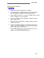
INSTALLATION
INSTALLATION
Installation of a System 25 requires the completion of a number of basic
steps, similar to those required to install any customer switching system.
Assuming that the building (station) wiring is already in place, the
recommended sequence of steps for installation of the system is as follows:
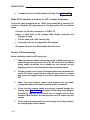
1.
Preinstallation Requirements
2. Install System Cabinets
3. Power Up and Initialize System
4.
Install Cross-Connect Equipment (See Note below.)
5. Install Modular Bulk Power Supply (Optional)
6. Connect Cabinets to Trunk Access Equipment
7. Connect Cabinets to Station Interconnect Panel (SIP)
8. Install Customer’s Peripheral Equipment
9. Install Terminals
10.
11.
Install Auxiliary Equipment
Test System
Note:
Step 4 can be done before Steps 2 and 3 if the crossconnect equipment is delivered before the cabinets.
2-1
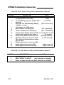
INSTALLATION
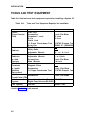
TOOLS AND TEST EQUIPMENT
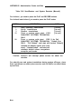
Table 2-A lists tools and test equipment required for installing a System 25.
Table 2-A.
Tasks
Install
Cross-Connect
Field
Unpack
Cabinet
Tools and Test Equipment Required for Installation
Tools Required
Push Drill
Screwdriver
Carpenter’s Level
Rule
Chalk Line
11 O-type Punch-down Tool
Adapter
Tin Snips
Utility Knife
Adjustable Wrench
Rule
Adjustable Wrench
Screwdriver
Allen Wrench
Recommended Type
8-inch Flat Blade
30-inch
30-inch
AT-8762 D-Impact Tool
BR866 JC (403608235)
6- or 8-inch
30-inch
6- or 8-inch
8-inch Flat Blade
1/8-inch
Install
Cabinets
or Add
Carriers
Add Voice
Terminals
Diagonal Pliers
or Install
Screwdriver
8-inch Flat Blade
AT-8762 D-impact Tool
Auxiliary
11 O-type Punch-down Tool
Equipment
Add
Screwdriver
8-inch Flat Blade
Circuit Packs (CPs)
Initialize
System Administration TerminalR S - 2 3 2 C
Digital Tape Unit (not RS-232C) —
System
Test System*
Test Set
Dracon TS21
☛
Used in Section 3 of this manual
2-2
INSTALLATION
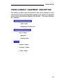
CROSS-CONNECT EQUIPMENT DESCRIPTION
This section provides a brief description of some of the System 25 crossconnect/interconnect equipment. More details on the System 25 equipment
can be found in the Reference Manual (555-540-200). This section describes
the following:
●
Trunk Access Equipment
700A Jacks
Emergency Transfer Unit
●
Station Interconnect Panel
— 617A Panel
Adapters
Fanning Strip
●
Cables
— Splitter Cables
— Octopus Cables
— Cable Labels.
2-3
INSTALLATION
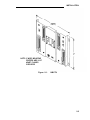
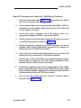
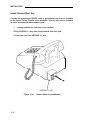
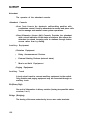
Trunk Access Equipment
The trunk access equipment (TAE) consists of 700A-I 10-61-25 or 700A-66B1 -25 (157BF) cut-down jacks, or equivalent, and up to four 10B Emergency
Transfer Units (ETUs). The 10B ETU is shown in Figure 2-1.
700A- 110-M-25 or 700A-66-B1-25 (157BF) Cut-Down Jack
Trunk circuits that appear on the network interfaces are grouped by trunk
type (Direct Inward Dialing [DID], Central Office [CO], or Tie) and punched
down on the 700A jack. One 700A jack is required for each RJ21 X or RJ2GX
network interface. The 700A-1 10-B1-25 jack has a 110-type cut-down field,
and the 700A-66-B1-25 (157BF) has a 66-type cut-down field. It is important
to note that most secondary wiring protectors (sneak current fuses) are
compatible only with the 66-type jack.
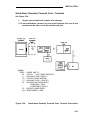
10B Emergency Transfer Unit (ETU)
During a power failure or system outage, each 10B ETU provides contact
closures for bypassing the switch and connecting up to five predesignated
FCC registered single-line voice terminals to telephone company trunks.
Connectorized cables (25-pair) connect the ETU to the 700A jacks, the
system cabinets, and the Station Interconnect Panel. A modular plug-ended
cord (part of octopus cable) connects control power (–48 V dc) from the
system cabinet.
Screw terminals that connect to relay contacts which may be used for an
external alerting device are also provided. The relay contacts close when a
failure occurs. (Any alerting device and associated power unit with a dc
current requirement less than or equal to 0.5 ampere may be used.) The ETU
also controls a DID make-busy contact that connects to the last pair on the
700A jack. For a more detailed drawing of the 10B ETU, see Install
Emergency Transfer Units (ETUs) in this part.
2-4
INSTALLATION
NOTE: 9“ WIDE, MOUNTING
CENTERS ARE 8-1/2”
APART, FLANGES
OVERLAPPED
Figure 2-1.
10B ETU
2-5
INSTALLATION
Station Interconnect Panel (SIP)
The SIP is the station cross-connect field and consists of the following
equipment:
●
617A
Panels
●
Adapters
●
50A Fanning Strips.
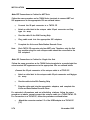
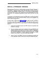
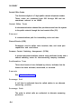
617A Panel
The 617A Panel is a metal plate with keyslot holes on each side for mounting
on a backboard. (See Figure 2-2.) Each 617A Panel can hold eight 2210A2
or 858A Adapters, each of which can accommodate six connections to the
port circuits in the cabinets. As many as five 617A Panels may be required
for a maximum size system. The adapters snap into prepunched holes on
the 617A Panels. (Reattached spacer buttons keep adapters from touching
the metal panels.)
The cable rings located at the top of the 617A Panel route the building wiring
cables to the adapters. Purse lock clips hold the building wiring cables in
place. The white posts at the bottom of the 617A Panel guide the wiring from
the 50A Fanning Strip to each column of adapters.
Preprinted boxes and numbers on the panel identify modular jacks for
record-keeping purposes.Letters are marked in the boxes at the top of each
column by the installer. The letter (A through J) and the corresponding
preprinted row number (1 through 24) identify the port jacks. For example,
Al identifies the modular jack located in column A row 1.
2-6
INSTALLATION
MOUNTING CENTERS
WHEN FLANGES ARE
OVERLAPPED
Figure 2-2. 617A Panel
2-7
INSTALLATION
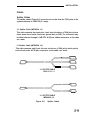
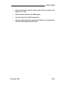
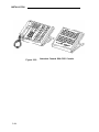
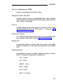
Adapters
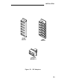
The adapters shown in Figure 2-3 are used at the SIP.
Z210A2 or 858A Adapters
These adapters connect the building wiring (station runs) to the station port
circuit packs (CPs) located in the system cabinets (through octopus cables).
As many as 40 of these adapters may be required for a maximum size
system, Any combination of the adapters can be used, depending upon the
type of building wiring. The port side of the adapters consists of six 8-pin
modular jacks. The station side of the adapters is equipped as follows:
●
●
Z210A2—Six 8-pin modular jacks used for terminating 4-pair
modular plug-ended D-inside wire (DIW). One of these adapters
must be installed at the top of column A on the SIP to provide
connections for the System administration Terminal (SAT), Digital
Tape Unit (DTU), etc.
858A—Six 11 O-type 8-pin wiring blocks used for terminating 4-pair
DIW.
WP90851, L1 Y-Adapter
This adapter separates voice and data pairs that are run over the same 4-pair
cable for connection through octopus cables to the System 25 port circuits.
This adapter plugs into the port side of either of the two adapters described
above. It has a DATA and a VOICE modular jack. The DATA jack connects
to a TN726 Data Line port circuit pack. The VOICE jack connects to a port
circuit on a Tip Ring Line, Analog Line, or ATL Line circuit pack.
2-8
INSTALLATION
Z21OA1
ADAPTER
858A
ADAPTER
Y-ADAPTER
WP90851,L1
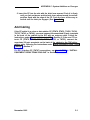
Figure 2-3. SIP Adapters
2-9
INSTALLATION
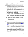
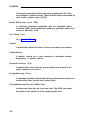
Fanning Strip
The 50A Fanning Strip (Figure 2-4) is a metal panel with positions to hold 16
octopus (switch) cables. The bundled portion of the octopus cable is
anchored at the fanning strip. The eight octopus cable cords hang free. One
fanning strip is required for 1-cabinet systems. Two fanning strips are
required for 2- or 3-cabinet systems.
NOTE : 9“ WIDE, 8-1/2”
MOUNTING CENTERS
WHEN FLANGES ARE
OVERLAPPED
Figure 2-4. 50A Fanning Strip
2-10
INSTALLATION
Cables
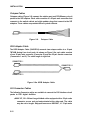
Splitter Cables
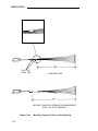
The splitter cables (Figure 2-5) connect trunk circuits from the 700A jacks to the
system cabinets or 10B ETU (3:1 only).
3:1 Splitter Cable (WP90929, L1)
This cable connects the twenty-four 1-pair trunk circuits on a 700A jack to three
8-port trunk circuit packs (loop start, ground start, or DID). The connection may
be either director through a 10B ETU. Al 25-pair ribbon connectors on the cable
are male.
2:1 Splitter Cable (WP90929, L3)
This cable connects eight 3-pair tie trunk circuits on a 700A jack to two 4-port tie
trunk circuit packs. All 25-pair connectors on the cable are male.
.
3:1 SPLITTER CABLE
WP90929,L1
2:1 SPLITTER CABLE
WP90929,L3
Figure 2-5.
Splitter Cables
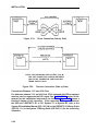
INSTALLATION
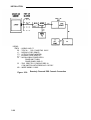
Octopus Cables
Octopus cables (Figure 2-6) connect the station port and CPU/Memory circuit
packs to the SIP adapters. Each cable consists of a 25-pair male connector that
connects to the switch cabinet and eight modular plugs that connect to the SIP
adapters. These cables are provided with all system cabinets.
Figure 2-6.
Octopus Cable
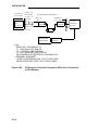
8536 Adapter Cable
The 853B Adapter Cable (104305834) connects two octopus cables to a 16-port
TN746B Analog Line circuit pack. As shown on Figure 2-6a, each cable consists
of one 25-pair male connector (Connector O) and two 25-pair female connectors
(Connectors 1 and 2). The cable length is eight feet.
CONNECTOR 1
CONNECTOR O
CONNECTOR 2
Figure 2-6a. 853B Adapter Cable
DS1 Connector Cables
The following Connector cables are available to connect the DS1 Interface circuit
packs to DS1 digital facilities:
●
2-12
H600 307, G2—50-foot long shielded cable equipped with a 50-pin male
connector on one end and unterminated at the other end. The cable
may be cut to length. Shipped loose are a KS23007, L1 15-pin male
INSTALLATION
connector and a KS23146,L3 50-pin male connector.
To connect a DS1 interface circuit pack to a 551-type Customer Service
Unit (CSU), field terminate the 15-pin plug.
To connect DS1 tie trunks on co-located System 25s, field terminate the
50-pin male connector (see Figure 2-1 9).
●
C6E connector cable (comcode 104307 434)—1 00-foot long shielded
cable equipped with a 50-pin male connector on one end and a 50-pin
female connector on the other end. This cable is used as an
“extension” cable between the DS1 Interface circuit pack and the other
connector cables.
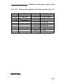
Cable Labels
A set of preprinted labels for identifying the system cabinet cables and ETU
cables are provided (Figure 2-7). The system cable labels are prenumbered to
identify the cabinet (1, 2, 3) and circuit pack slot (1-12, - see NOTE) and are also
color-coded as follows:
Note: Because of the combined CP/Memory board in R2V1 and R3,
ten slots are available in Cabinet 1.
I
Cabinet No.
1
2
3
Color
I
Blue
Orange
Green
The call processor octopus cable labels and ETU cable labels are white. The
use of these labels is discussed in this manual.
2-13
INSTALLATION
AT&T
CAR 1
CABLE
LABELS
CAB1 SLOT1
CAB1 SLOT1
CAB1 SLOT2
CAB1 SLOT2
CABl SLOT3
CAB1 SLOT3
CAB1 SLOT4
CAB1 SLOT4
CAB1 SLOT5
CAB1 SLOT5
CAB1 SLOT6
CAB1 SLOT6
CAB1
SLOT7
CAB1 SLOT7
CAB1 SLOT8
CAB1 SLOT8
CABl SLOT9
CAB1 SLOT9
CAB1 SLOT10
CAB1 SLOT10
CAB1 SLOT11
CAB1 SLOT11
CAB1 SLOT12
CAB1 SLOT12
AT&T
CABLE
CALL
PROCESSOR
OCTOPUS
AT&T
LABELS
SYSTEM
ADMIN
TERM
SYSTEM
ADMIN
TERM
SMDR
SMDR
DIGITAL
TAPE
UNIT
DIGITAL
TAPE
UNIT
REMOTE
MAINT
REMOTE
MAINT
ETU1
SWITCH(CPU)
ETU1
SWITCH(CPU)
ETU2
SWITCH(CPU)
ETU2
SWITCH(CPU)
CABLE
ETU
LABELS
ETU 1 SIP
ETU 1 SIP
ETU 2 SIP
ETU 2 SIP
ETU 3 SIP
ETU 3 SIP
ETU 4 SIP
ETU 4 SIP
ETU
ETU
SIP
SIP
SWITCH(TRUNK) SWITCH(TRUNK)
SWITCH(TRUNK) SWITCH(TRUNK)
SWITCH(TRUNK) SWITCH(TRUNK)
SWITCH(TRUNK) SWITCH(TRUNK)
SWITCH(LINE)
SWITCH(LINE)
SWITCH(LINE)
SWITCH(LINE)
SWITCH(LINE)
SWITCH(LINE)
n
CAB1 SLOT
CAB1 SLOT
SWITCH(LINE)
SWITCH(LINE)
CAB1 SLOT
CAB1 SLOT
SWITCH
SWITCH
CAB1 SLOT
CAB1 SLOT
SWITCH
SWITCH
ETU 1 CO
ETU 1 CO
ETU 2 CO
ETU 2 CO
ETU 3 CO
ETU 3 CO
ETU 4 CO
ETU 4 CO
ETU
CO
ETU
CO
ETU
CO
ETU
CO
WHITE
CAB 1
BLUE
CAB 2 - ORANGE
CAB 3 - GREEN
Figure 2-7.
2-14
Cable Labels
INSTALLATION
Symbols Used in Figures
Modular jacks are shown by the triangle symbol. The 25-pair connectors are
indicated by shaded blocks. Generally, only one leg of an octopus cable is
shown. Unterminated wiring requiring cut down or other termination does not
show symbolic designations. The 103A Connecting Block is a typical
modular wall jack that provides cut-down connections for building (station)
wiring and a modular jack for connection to terminal equipment.
2-15
INSTALLATION
PREINSTALLATION REQUIREMENTS
The AT&T System 25 Reference Manual (555-540-200) provides a complete
listing of System 25 equipment location requirements. Before installation
begins, check the items described in this section.
Caution: System 25 cross connect hardware must be located in a
restricted access area only.
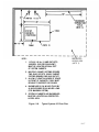
Table and Backboard
Verify that an equipment table and cross-connect backboard are installed.
(See Figure 2-8 for a sample layout.) The cross-connect backboard is a 48inch by 96-inch by 3/4-inch plywood panel, mounted horizontally 30-inches
above the floor and within 5 feet of the location chosen for the cabinets.
If wall space in the equipment room is limited, an alternate layout may be
provided. If more than four 617A Panels are required, this alternate layout
will require more than one 48-inch by 96-inch plywood panel. See Install
Equipment Room Station Cabling for details.
Network Interface
The RJ21X network interface (CO lines) installed by the telephone company
must be located within 25 feet of the system cabinets. In addition to the
RJ21X network interface, an RJ2GX interface is required for tie lines. For T1
interfaces, RJ48X network interfaces must be provided. If System 25 is
replacing another system and no additional lines are required, the network
interfaces used with the previous system should already be in place.
The network interfaces should also include a coupled bonding conductor
extended from the building service entrance.
2-16
NOTES :
RESTRICTED
1. 115V AC, 60 Hz, 15 AMP OUTLETS
(HUBBELL 5262 OR EQUIVALENT)
MUST BE LOCATED WITHIN 4 FEET
OF SYSTEM CABINETS.
ACCESS AREA
(NOTE 5)
2. MULTIPLE CABINET SYSTEMS REQUIRE
TWO QUAD OUTLETS, SINGLE CABINET
SYSTEMS REQUIRE ONE QUAD OUTLET.
3. ALLOW AT LEAST 24 INCHES OF SPACE
IN FRONT OF CABINETS. TABLE MUST
BE ABLE TO SUPPORT 250 POUNDS.
4. BACKBOARD IS 3/4 INCHES THICK BY
48 INCHES WIDE BY 96 INCHES LONG
(FOR MAXIMUM SYSTEM).
5. SYSTEM 25 CABINETS AND BACKBOARD
MUST BE LOCATED IN A RESTRICTED
ACCESS AREA.
Figure 2-8.
Typical System 25 Floor Plan
2-17
INSTALLATION
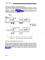
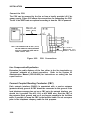
AC Power
All cabinets and any locally-connected System 25 peripheral equipment
(System Administration Terminal [SAT], Station Message Detail Recording
[SMDR] device, Digital Tape Unit [DTU]), and Customer Service Unit (CSU)
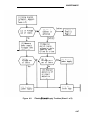
used for DS1 connections must be plugged into the common ac power outlet.
This outlet must have an associated ground block connected to an approved
building ground, using #6 AWG copper wire. (This ground block is the
system’s single-point ground.)
A 1-cabinet system requires one quad ac outlet. A 2- or 3-cabinet system
requires a second quad outlet and two separately fused 15-ampere circuits.
Additional ac outlets may be needed for auxiliary equipment. All ac outlets
must have the safety ground (green wire) cross-connected to the single-point
ground block on the first quad outlet. (See Figure 2-9.)
Local options may require that surge protectors be used for all peripheral
equipment used with the System 25, including the Customer Service Unit
(CSU).
Grounding
For proper grounding instructions, refer to the AT&T System 25 Electrical
Protection and Exposure Check List (555-500-1 20).
Warning:
Verify that the building ground has been provided by
one of the methods listed below, that ac power uses
approved building ground for its primary ground, and
that all voltage limiting devices are grounded to building
approved ground. Improper ground can result in
equipment failures and service outages from lightning
induced surges on the power lines.
An approved building ground for System 25 may be one of the following,
listed in decreasing order of preference:
1.
Building steel.
2. Acceptable water pipe— a metal underground water pipe at least 1/2
inch in diameter, in direct contact with the earth for at least 10 feet.
The pipe must be electrically continuous (or made electrically
continuous by bonding around insulated joints, plastic pipe, or plastic
water meters) to the point where the protector ground is connected.
A metallic underground water pipe must be supplemented by the
2-18
INSTALLATION
metal frame of the building, a concrete encased ground, or a ground
ring. If these grounds are not available, the water pipe ground can
be supplemented by one of the following types of grounds.
●
●
●
●
Metal underground gas piping system—an electrically
continuous metal underground gas piping system that is
uninterrupted with insulating sections or joints and without
an outer nonconductive coating.
Other local metal underground systems or structures—local
underground structures such as tanks and piping systems.
Rod and pipe electrodes— a 5/8-inch (solid rod) or 3/4-inch
(conduit or pipe) electrode driven to a minimum depth of 8
feet.
Plate electrode—expose a minimum of 2 square feet of
metallic surface to the exterior soil.
3.
Concrete encased ground—defined to be an electrode, consisting of
at least 20 feet of one or more steel reinforcing rods at least 1/2 inch
in diameter, or 20 feet of bare copper conductor not smaller than #4
AWG encased in 2 inches of concrete. This electrode must be
located within and near the bottom of a concrete foundation or
footing that is in direct contact with the earth.
4.
Ground ring consisting of at least 20 feet of bare copper conductor
not smaller than #2 AWG encircling the building. The ground ring
must be in direct contact with the earth and buried at least 2.5 feet
below the earth’s s u r f a c e .
Lightning Protection
System 25’s lightning protection plan involves five distinct but interdependent
items required at every installation:
●
Primary protection in the form of voltage limiters (typically carbon
blocks or gas tubes) on all pairs that leave the building, whether
aerial or buried. These devices bypass surges to approved building
ground and limit potential differences between T/R pairs and building
ground to less than 1500 volts.
2-19
INSTALLATION
●
●
●
A single-point ground (SPG) system in which the green wire ground
(system ground) and the telephone company ground are connected
to approved building ground.
The coupled bonding conductor must be connected between the
telephone company ground at the building entrance and System 25’s
SPG.
Surge protection on the ac power to System 25.
For greater than 99 percent of all lightning strikes, the protection outlined
above will do the job. However, there are a few locations where the
described protection may not be sufficient. External secondary protection,
located at the trunk access area of the System 25 cross-connect field, can be
employed.
Several commercial units are available. If 66-type block terminations are
used, a very convenient device is the LP5-230-220 Fused Lightning Protector.
This unit plugs into the 66-block (in place of the shorting bars) and includes
the sneak current fuse. One unit is required per protected pair. A ground
bar is provided with the lightning protection units or can be ordered
separately (Comcode 901-007-120). All lightning protectors located in the
System 25 cross-connect area must be grounded to System 25’s SPG via a
#6AWG copper wire.
In addition, an AC Surge Suppressor (Tll Model 428) may be required. Local
practice should be followed. The unit plugs directly into one of the quad
outlets and provides a dual outlet to protected equipment. Sufficient units
should be provided to protect all at-powered equipment. Each cabinet in the
system requires a protected outlet, and in addition, a protected outlet is
required for each auxiliary unit, such as the SAT, a tape unit, or a printer.
When a Surge Suppressor is used, all peripheral equipment directly
connected to System 25 must be connected to alternating current via the
Surge Suppressor.
2-20
INSTALLATION
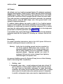
Secondary Protection
External secondary protection, located at the trunk access area of the
System 25 cross-connect field, is required for all trunks and off-premises
lines. Refer to Table 2-B for approved trunk protectors.
FROM AC
LOAD CENTER
(TWO SEPARATELY
FUSED 15 AMP
CIRCUITS)
H
LOAD
CENTER
II
GROUND
(GREEN)
(#14 AWG)
I
I
4“ BOX (RACO 230
OR EQUIVALENT)
HUBBELL RECPTS.
( 5262 15 AMP
OR EQUIVALENT)
4“ COVER (RACO 807
OR EQUIVALENT)
SINGLE
POINT
GROUND
/
GROUND BAR MOUNTED ‘
ON 4“ BOX (SQUARE D
PK9GTA OR APPROVED
EQUIVALENT)
Figure 2-9.
TO CABINET NO. 1
GROUND BLOCK (MAX.
LENGTH = 2 0 F T . )
APPROVED
BUILDING GROUND
(#6 AWG, COPPER)
AC Power Distribution—Multiple Cabinet System
2-21
INSTALLATION
Building Wiring
Building (station) wiring (must be 24 AWG or heavier) from voice and data
terminals to the equipment location should already be in place. System 25
wiring requires that 4-pair circuits be distributed from the equipment location
to each station’s wall jack. The SIP hardware (Figures 2-2 through 2-6),
designed specifically for this purpose, is furnished with each system. Except
in extraordinary circumstances, this cross-connect hardware must be used.
In unusual circumstances where the 617A Panels are not used and some
other cross-connect equipment that does not provide a modular jack interface
to the port circuits is used, separate 4-pair circuits must be run for the voice
and data terminal at the workstation.
All examples and instructions in this manual assume that a SIP is used.
The station wiring terminations in
the equipment area should have been
labeled to indicate the room location and jack number of the other end of the
line. When SIP connections are made, the connection information should be
entered on the Voice and Data Station Records Form (see Install Equipment
Room Station Cabling in this part for details).
2-22
INSTALLATION
INSTALL SYSTEM CABINETS
Before beginning the cabinet installation, position the cabinet table within 2
feet of the ac power receptacle. Make sure that the cabinets are easily
accessible from both the front and the back.
Position Cabinet(s)
Caution: A fully-equipped cabinet weighs 80 p o u n d s .
1.
Unscrew and remove the upper rear panel of each cabinet. Do not
unscrew the lower part with the 12 connectors.
2.
Near the center of the backplane, note an address plug in one of the
positions marked 1, 2, or 3 on the black address strip. (Position 4 is
not used.) This indicates the cabinet number for software purposes.
The position of the plug (1, 2, or 3) should agree with the position of
the cabinet (Cabinet 1 on the bottom, etc.).
3.
Use the CAB 1, CAB 2, and CAB 3 labels from the cable label sheets
(Figure 2-7) to label each cabinet. Position the cabinet label in the
box adjacent to connector 12 on the lower back panel. (The number
may have already been stamped by the factory.)
4.
Stack the cabinets on top of one another on the stand. If there is
more than one cabinet, stack Cabinet 1 on the bottom arid Cabinet 3
on the top. Cabinet 1 contains the CPU/Memory (ZTN129 or
ZTN130 [R3]), and Service (ZTN85 or ZTN131 [R3]) circuit packs
(Figure 2-1 O). Do not replace the upper back panels yet.
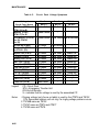
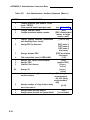
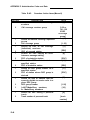
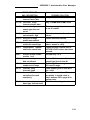
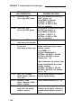
Check Cabinet Contents
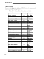
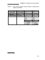
Check to make sure that the cabinets have been delivered with the correct
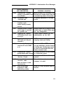
circuit packs (CPs). Table 2-B lists available CPs, their functions, and their
protectors. If the system has TN760B Tie Trunk CPs, you may also have to
set the option switches on the CPs. See “Set TN760B Option Switches” in
Appendix C for details.
November 1995
2-23
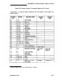
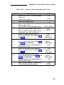
INSTALLATION
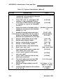
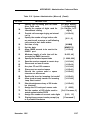
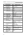
Table 2-B. Circuit Packs, Their Functions, and Protectors
Approved Secondary
Wiring Protector
N/A
Circuit Pack
Function
ZTN78
SCP-1 or 79A
TN742
lTW/LlNX343* I ROB
ZTN79
ITWILINX343* lROB
N/A
TN735
TN726
N/A
SCP-1 , SCP-2, SCP-3,
or LP5-230-220
SCP-1 , SCP-2, SCP-3,
or LP5-230-220
SCP-1 or 79A
TN758
ZTN76
Supports single-line voice terminals.
(Must not be used on out-of-building
circuits, )
Supports off-premises, out-ofbuilding, and bridged single-line
voice terminals.
Supports the 7300H Series voice
terminals used with a MERLIN®
system. (Requires local (set) power
for distances beyond 1000 feet.)
Supports MET sets.
Supports data terminals and
computers.
Contains pooled modems.
Supports ground start trunks.
ZTN77
Supports bop start trunks.
TN753
SCP 1 or 79A
N/A
N/A
N/A
SCP-1 or 79A
N/A
TN760B
TN763
ZTN130 (R3)
TN748B
TN767
ZTN131 (R3)
SCP-1 or 79A
TN747E3
lTW/LlNX343* I ROB
TN762B
Supports direct inward dialing trunks.
(DID)
Supports tie trunks.
Supports auxiliary equipment.
Call processing/memory.
Tone Detector.
Provides DS1 Interface.
Provides system clocks, tone
generators, detectors, and DS1
synchronization.
Supports ground start or loop start
trunks.
Supports hybrid voice terminals.
Must be vintage 4 or later.
*Note: lROB unit ITW341 has been replaced. Use model lTW/LlNX343 only.
2-24
November 1995
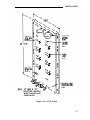
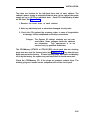
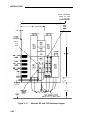
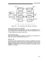
INSTALLATION
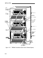
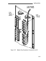
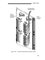
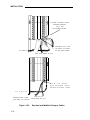
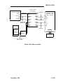
Two fans are located on the left-hand front side of each cabinet. The
cabinet’s power supply is located behind the fans; to the right of the power
supply are up to 12 CPs in individual slots. Each CP is identified by a label
on the front. See Figure 2-10.
1. Remove the front cover of each cabinet.
2. Note any obviously bent or otherwise damaged circuit packs.
3. Check the CPs against the customer order. In case of irregularities
or damage, follow established notification procedures.
Danger: The System 25 cabinet contents are not user
serviceable. Some voltages inside the cabinets
This equipment is to be
are hazardous.
serviced only by qualified technicians.
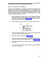
The CPU/Memory (ZTN129 or ZTN130 [R3]) circuit pack has two shorting
plugs that are used for factory tests (see Figure 2-1 1). They should have
been removed at the factory. If these shorting plugs have been accidentally
left in by the factory, the system may cold start when it should warm start.
Check the CPU/Memory CP; if the plugs are present, remove them. The
shorting plugs are located on the component side of the circuit pack.
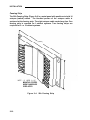
2-25
INSTALLATION
Figure 2-10.
2-26
Three-Cabinet System, Front View With Covers Removed
INSTALLATION
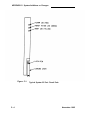
Figure 2-11.
Position of Shorting Plugs on CPU/Memory Circuit Pack
2-27
INSTALLATION
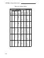
Required Circuit Pack Positions
The required CP positions for Cabinet 1 are:
SLOT
1
I
2
CP
ZTN129 or ZTN130 (R3)
I
ZTN85 or ZTN131 (R3)
Also, all DID Trunk circuit packs should be installed in Cabinet 1.
There are no other restrictions on CP position in a single-cabinet or
multicabinet system; however, you should refer to the power supply unit load
requirements for the maximum unit loads for each CP type within a single
cabinet.
Caution: Be careful not to exceed unit load restrictions on each
cabinet.
Label Connectors on Back Cover
Each cabinet has twelve 25-pair receptacles across the bottom of the rear
panel. These connectors link the CPs inside the cabinet to the Station
Interconnect Panel (SIP) and Trunk Access Equipment (TAE). The connectors
are numbered from 1 to 12 and correspond to the CP slots.
Using a felt-tipped pen, write the CP code for each slot in the box above the
connector number on the lower rear cover.
2-28
INSTALLATION
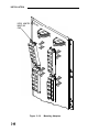
Install 4A Retainer Clips
The 4A retainer clips must be installed on each of the 12 receptacles on the
lower rear panel of the cabinets. To install a clip, position it and insert the
legs in the cabinet as shown in Figure 2-12.
Figure 2-12.
4A Retainer Clip Installation
2-29
INSTALLATION
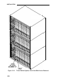
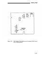
Connect Cabinets
The Time Division Multiplex (TDM) bus extender cable and the intercabinet
#6 AWG ground wire must be connected between cabinets. The TDM bus
terminates on each side of the cabinet, and the intercabinet #6 AWG ground
wire connects to the ground block at the rear of each cabinet.
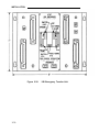
Note: Make certain that the address plug is installed in the rear pin
field of each cabinet (see Figure 2-13).
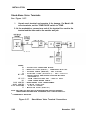
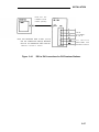
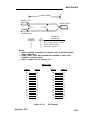
TDM Bus Connections
One end of the TDM bus is terminated by resistors mounted on the ZTN129
or ZTN130 (R3) CP. This CP is always in slot 1 of Cabinet 1. The other end of
the TDM bus is terminated by a Bus Terminator that plugs into the upper pin
field of the topmost carrier (which may, of course, be the only cabinet). These
connections are shown in Figure 2-13.
Whenever a cabinet is added, the Bus Terminator must be moved to the end
of the bus on the new top cabinet. This can be either slot 1 or slot 12,
depending on the number of cabinets and how the TDM bus extender cable
is run.
When removing a Bus Terminator and TDM bus extender cable, take care not
to bend the backplane pins.
1.
Verify that the Bus Terminator is in the proper position:
●
Slot 12 of Cabinet 1 for 1-cabinet systems
●
Slot 1 of Cabinet 2 for 2-cabinet systems
●
Slot 12 of Cabinet 3 for 3-cabinet systems.
2. See Note. For 2- and 3-cabinet systems, install extender cable
between slot 12 of Cabinet 1 and slot 12 of Cabinet 2. For 3-cabinet
systems, install another extender cable between slot 1 of Cabinet 2
and slot 1 of Cabinet 3.
Note: When properly installed, the light blue stripe on the
extender cable is at the bottom of the cable and the
lettering on the cable (SER=1, for example, is right
2-30
INSTALLATION
side up).
3.
Install the upper rear panels. Route the extender cable between
the slots formed by the upper and lower rear panels.
2-31
INSTALLATION
TDM
BUS
TERM
CARD
~CABINET 3
ADDR
PLUG
ON/OFF
.SWITCH
AC POWER
# 6 AWG
BUILDING
GROUND
WIRE
TDM B
EXTEN
CABLE
CABINET
AC POWER
ADD
PLU
.
#6 A W G
PLUG
Figure 2-13.
2-32
TDM Bus Terminations (Rear View of 3-Cabinet System)
2
INSTALLATION
Ground Wire Connections
The cabinets are connected to the single-point ground with #6 AWG copper
wires. (Building ground requirements are described in Preinstallation
Requirements in this section.)
Warning: The cabinet power switches must be set to off.
1.
In 2- or 3-cabinet systems, connect a #6 AWG wire between the
ground blocks of Cabinets 1 and 2 and Cabinets 1 and 3.
2. Connect a #6 AWG wire between the ground block of Cabinet 1 and
the single-point ground. (See Figures 2-9 and 2-1 3.)
POWER UP AND INITIALIZE SYSTEM
Separate power cords for each cabinet must be plugged into the designated
quad outlets. Peripheral equipment (SAT, SMDR [Station Message Detail
Recording], or CAS [Call Accounting System], DTU and CSU [Customer
Service Unit]) collocated with the switch cabinet(s) must also be plugged into
these ac outlets.
Connect Power
1.
Make sure the rear panel is in place on each cabinet.
2.
Connect the receptacle end of a 3-wire power cord to the plug at the
rear of each cabinet.
3.
Connect the power cord’s plug end to the quad ac outlet for each
cabinet.
4.
Recheck the electrical and ground connections.
Danger: Once power is applied, do not put your hands or
any tools into the cabinet.
2-33
INSTALLATION
5.
Starting with Cabinet 2 or 3, turn on the power switch on each
cabinet [Cabinet 1 must be last).
IMPORTANT: If power to Cabinet 1 is not turned on last, the
cold start initialization may not occur properly.
6.
Check to be sure that the cabinet fans are rotating.
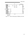
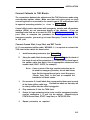
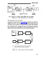
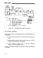
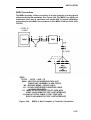
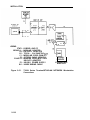
Connect Administration Equipment
Connect the SAT and DTU to their respective modular jacks on an 858A
Adapter at the SIP.
If the SIP has not yet been installed, connect an octopus cable to Cabinet 1,
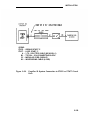
slot 1. Make temporary connections as shown in Figure 2-14 to the SAT and
Note: The direct octopus cable connections are only temporary.
All permanent connections to peripheral and station
LEGEND :
ZTN129 cl 355A ADAPTER 355AF ADAPTER -
CPU/MEMORY CP
OCTOPUS CABLE ( WP90780 )
RS-232 PLUG TO MODULAR JACK
RS-232 RECEPTACLE TO MODULAR JACK
NOTE :
LEG 1 CONNECTS TO SAT; LEG 3 CONNECTS TO DTU.
Figure 2-14. Temporary SAT and DTU Connections
2-34
INSTALLATION
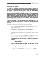
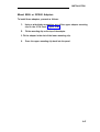
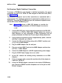
Cold Start the System
To ensure that the system recognizes the current position of the CPs, you
must cold start the system before beginning initialization. A cold start causes
the system to check all slots for valid CP types and assign default
translations to ail ports (except auxiliary trunk ports).
A limited cold start is available. The limited cold start does not assign default
translations to ports. The limited cold start is useful if the customer’s dial
plan is significantly different from the System 25 default plan. You do not
have to delete the default codes before you enter the true dial plan. See the
Administration Manual (555-540-500) for a listing of default translations
provided in Release 3 systems.
The time required for a cold start depends on the number of CPs in the
system, but is usually several minutes. A limited cold start takes about 30
seconds.
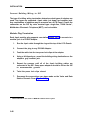
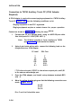
Follow these steps to manually start the system from the SAT:
1.
Connect the SAT to the CPU/Memory CP administration port, (leg 1
of the octopus cable).
2.
If the SAT has a selectable baud rate, set it to 1200 baud.
3.
Be sure transmission parity is set to none, with the parity bit set to
space (0).
4.
Turn the terminal on and press the carriage return key once or twice.
On most terminals, this key is <RETURN> or <ENTER>.
After communication with the system is established, a prompt is
displayed:
Enter Password ->
5.
Enter SYSTEM25 and press <RETURN>. The main menu will now
be displayed along with the prompt:
Make one selection from menu ->
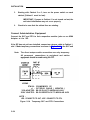
6.
Enter 9 (for the SAVE/RESTORE selection) and press <RETURN>.
2-35
INSTALLATION
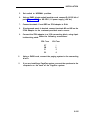
7. The system will respond with:
Action=
8. Enter 20 for a cold start. The system will respond with:
Save/Restore: Action=20 Data=
9. Enter D. The system will complete the word Data followed by the =
sign.
10.
Enter 1 for a cold start or 2 for a limited cold start. The system will
respond with:
Save/Restore: Action=20 Data=1 (or Data=2)
You are about to initiate a cold start
.
c to continue, any other key to abort
11.
Enter c to initiate the cold start.
Typing errors can be erased by pressing the backspace key. Each time you
press the backspace key, one character is erased.
2-36
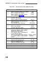
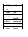
INSTALLATION
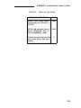
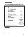
Cold and warm starts both display the same type of information on the SAT. This
consists of a listing of the version of the firmware loaded in the CPU/Memory
CP, followed by a configuration listing of all CPs recognized by the system. The
CPU/Memory CP is not in the configuration listing; however, it is located in slot 1
of Cabinet 1.
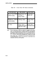
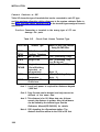
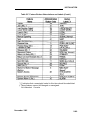
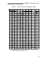
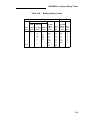
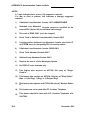
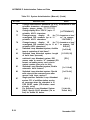
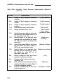
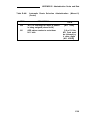
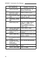
Table 2-C provides a listing of SAT messages that may be displayed during a
cool or warm start. The displayed message is a result of CP occupancy, type,
and port translations.
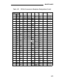
Table 2-C. Displayed SAT Messages During Cold or Warm Restart
Circuit Pack (CP)
in Slot
Port Translated
Displayed
Message
No
Yes
Missing
Yes
No
CP Type Listed #
Yes
Yes
CP Type Listed
Yes
Yes (doesn’t match
physical CP)
CP Type Listed*
Yes (Unsupported
CP Type)
Yes or No
†
Illegal
† Warm restart only.
# Mark indicating that the CP is unused.
* Mark indicating that the CP is mismatched.
November 1995
2-37
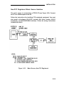
INSTALLATION
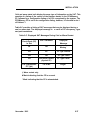
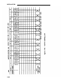
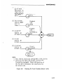
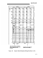
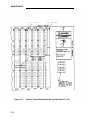
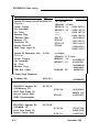
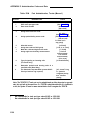
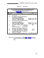
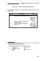
The SAT message for a cold or warm start appears after the system has
performed all self-tests and reading of its configuration. Typical cold start SAT
message is as follows. The example is for a 2-cabinet system.
Typical Release 3 Version 3 Cold Start Message
RESTART
TS ROM pair
FC ROM pair
FC ROM pair
FC ROM pair
COLD START
1:version 3.5 *
1:version 3.13 ●
2:version 3.13’
3:version 3.13 *
Default Password in Effect
SLOT
1
2
3
4
5
6
7
8
9
10
11
12
CABINET 1
ZTN85 06
ZTN79 03
ZTN79 03
ZTN79 03
ZTN79 03
ZTN78 02
ZTN78 02
ZTN78 02
TN74703
TN74703
TN748 06
CABINET 2 CABINET 3
TN75304
TN760B 05
TN760B 05
TN760B 05
TN760B 05
* This is important information that should be noted in trouble reports.
Message: Type <RETURN> for prompt.
Enter <RETURN>. The system will respond with the administration prompt:
SYSTEM 25 ADMINISTRATION
(CPU/Memory release information)
AT&T Copyright 1988
Enter password -->
2-38
November 1995
INSTALLATION
Check Performance of Cabinet Components
Each CP has three colored LEDs on the front panel that indicate whether it is
functioning properly or not. When a cold start is performed, the system
undergoes a series of self-tests and loads default translations.
Upon initial power application, each CP tests itself. The red LED on the CP
lights to indicate that the test is in progress. Once the CP passes its initial
tests, the red LED goes off. Then, after the main processor recognizes the
CP and can communicate with it, the green LED lights. When all green LEDs
are lighted, the testing and loading process is complete. This process takes
about 3 minutes.
1.
Make sure that both fans in each cabinet are on and operating.
2. Make sure that the green LED on the power unit behind the fan
assembly is lighted.
3. Check the CP LEDs. Table 2-D lists the LED status of each type of
CP.
2-39
INSTALLATION
Table 2-D.
Circuit Pack Type
LEDs if Normal
LEDs if Failed
Service Circuit (ZTN85
or ZTN131 [R3])
Steady Green and
Flashing or
Steady Amber
Steady Red or
Amber Off
CPU/Memory (ZTN129
or ZTN130 [R3])
Flashing Green
Steady Green
or Off
All Other
Steady Green
(Amber Also lighted
when CP in use)
Steady Red
(see Note below)
Note:
2-40
Circuit Pack LED Status Indications
The red and green LEDs can both be lighted at the same
time. In normal operation, a lighted red LED indicates that
an alarm has been recorded for that CP. If the green LED is
also lighted, the main processor can communicate with the
CP. A lighted amber LED indicates that a resource on the
CP is being used. A lighted red LED and a dark green LED
indicates that the CP diagnosed itself to be so bad that it has
removed itself from the system.
INSTALLATION
If all the CPs are operating properly, only the green LED on the CPU/Memory CP
and the amber LED on the Service Circuit should be flashing. If any other CP
has a no-lighted LED, the CP may need to be reseated. All port CPs green LED
remains dark until at least one port on the CP has been translated.
Except for the CPU/Memory CP and Service Circuit CPs, power can be left on
while a CP is reseated. To reseat a CP, do the following:
1.
See CAUTION. Make sure your hands are clean and dry. Put on a wrist
grounding strap, and clip it to the grounding block at the rear of the
cabinet.
Caution: Static electricity can damage a CP.
2.
With your thumb, pull up on the latch pin of the removal lever. (See
Figure 2-15.)
3.
When the latch pin is up, pull the removal lever down until it stops, at an
angle of about 30 degrees to the floor.
4.
Tugging hard, pull the CP out a few inches. Leave it out for at least 30
seconds, and then push it back firmly into its slot. When it is almost back
in place, you’ll feel resistance. The removal lever will start to return to its
vertical position.
5.
Push the lever all the way to vertical until it catches on the latch pin.
6.
After the power-up, repeat this process for each CP with dark LEDs
(except for ZTN129 orZTN130 [R3] and TN763s).
7.
Recheck the LEDs on all CPs. (If a CP’s LEDs are not lighted, the CPs
are considered “unadministered” by the CPU. ) A lighted red LED on any
CP indicated that it is faulty.
November 1995
2-41
INSTALLATION
Figure 2-15.
Typical System 25 Port Circuit Pack
Report Problems
Follow local procedures to report faulty or damaged equipment.
2-42
November 1995
INSTALLATION
Initialize System
Instructions for initializing the system (based on the completed
implementation forms) are provided in the Administration Manual
(555-540-500).
Note:
Before trunks using DS1 Signaling are administered, all link
level parameters such as signaling and framing and all link
level alarms must be cleared. If this is not possible, PBXs at
each end will not work. If this condition exists, clear a
maintenance busy condition that exists at each end.
INSTALL CROSS-CONNECT EQUIPMENT
Before starting, familiarize yourself with the following equipment described in
CROSS-CONNECT EQUIPMENT DESCRIPTION:
●
Trunk Access Equipment (TAE)
700 A-110-B1 -25 or 700A-66-B1-25 Wiring Jacks
10B Emergency Transfer Units
●
Station
Interconnect Panel (SIP)
617A Panels
858A or Z210A2 Adapters
50A Fanning Strips.
Figure 2-16 shows a typical SIP and TAE backboard layout. Figure 2-17
shows an alternate layout that can be used when horizontal wall space is
limited. These layouts can be reversed when the switch cabinet(s) must be
installed to the right of the backboard.
2-43
INSTALLATION
Install TAE, 617A Panels, and Fanning Strips
To install this equipment, proceed as follows:
1.
For each RJ21X, RJ2GX, and RJ48X network interface, install one
700A Jack 1/2-inch from the edge of the backboard closest to the
switch cabinet(s).
2.
Mount the first 617A Panel.
3.
Position and mount the first 50A Fanning Strip next to the 617A
Panel. The edges should overlap so that the same screws will go
through the overlapping key slots in the 50A Fanning Strip and the
617A Panel. The bottoms of the fanning strip and panel are flush.
4.
If required, mount a second 50A Fanning Strip above the first.
5.
Mount the first 10B Emergency Transfer Unit (ETU) in the position
shown in Figure 2-16 or Figure 2-17. Overlap the edges of the ETU
and the panel so that the same screws will go through the
overlapped key slots.
6.
Mount the remaining 617A Panels. Overlap the panels to conserve
space and to reduce the number of screws required; however, do
not mount more than three panels on either side of the 50A Fanning
Strip.
7.
If required, install the second ETU above the first.
8.
If additional ETUs are required, install them close to the 700A Jacks
(Figure 2-1 6). If the alternate SIP arrangement (Figure 2-17) is used,
install additional ETUs above the second ETU.
9.
Using a felt-tipped pen, letter the adapter columns (A through J) on
the 617A Panels, starting with the left side. For the alternate
arrangement, start with the left side on the lower row.
10.
Using a #12 AWG ground wire, connect the ground points on the
ETUs (screw terminal on the upper left side) and link them to the
single-point ground.
11.
Install D rings as required below the 700A Jacks and 617A Panels.
2-44
INSTALLATION
F I R S T
1 0 8
E T U
P L Y W O O D
BACKBOARD
1/2"
ADD'L 700A
BLOCK
ADD'L 700A
BLOCK
ADD'L
E T U
ADD'L 700A
BLOCK
ADD'L 700A
BLOCK
ADD'L
ETU
700A
BLOCK
ADD'L
617A
PANEL
ADD'L
617A
PANEL
ADD'L
617A
PANEL
ADD'L
ETU
7 0 0 A
BLOCK
TO SWITCH
CABINET
ADD'L
6 1 7 A
PANEL
D-RINGS AS REQ'D
FLOOR
FIRST 50A
FANNING
STRIP
Figure 2-16.
FIRST
617A
PANEL
FREE HANGING OCTOPUS
CABLE WITH 65" FREE LENGTH
SIP and TAE Backboard Layout
2-45
INSTALLATION
NOTE: GREATER
THAN
48"
FOR
5-PANEL
ARRANGEMENT
FIRST
108
ETU
Figure 2-17.
2-46
Alternate SIP and TAE Backboard Layout
INSTALLATION
Mount 858A or 2210A2 Adapters
To install these adapters, proceed as follows:
1.
Using a wide blade screwdriver, pry off the upper adapter mounting
clip on the 617A Panel (Figure 2-18).
2.
Fit the mounting clip on the top of the adapter.
3. Fit the adapter in the slot of the lower mounting clip.
4.
Press the upper mounting clip back into the panel.
2-47
INSTALLATION
UPPER ADAPTER
MOUNTING
CLIP
Figure 2-18.
Mounting Adapters
INSTALLATION
INSTALL MODULAR BULK POWER SUPPLY
(Optimal)
The 346 Modular Bulk Power Supply (MBPS) is a cost-effective and flexible
alternative to the KS-2291 1 power supply. The 346 MBPS can be used
where the wall-mounted (outlet) KS-2291 1 power supply cannot be used or
where multiple KS-2291 1 power supplies are required.
The 346 MBPS consists of the 346A Power Unit and 346A1 Power Panel. Up
to three 346A Power Units can be mounted in a power panel. Each 346A
Power Unit is capable of powering four terminals with adjuncts (“1 O w“
position), for a total of 12 terminals. Terminals powered by the 346A Power
Unit can be located up to 1000 feet from the unit.
The 346 MBPS should be installed near the SIP. Service to the ac outlet
powering the 346 MBPS must be a dedicated (nonswitched) 20-ampere line.
A maximum of four power panels can be connected to the 20-ampere line.
The AC Surge Suppressor (T11 Model 428) should be used with the 346A1
Power Panel.
INSTALL EQUIPMENT ROOM TRUNK CABLING
As mentioned earlier, all outside lines must be connected to the system
through connectorized network interfaces. These interfaces are connected to
wall-mounted trunk access equipment (TAE), and from there to the cabinets.
Connect Network Interfaces to TAE Blocks
The trunks and off-premises stations from the network interface must be cut
down on the TAE’s connecting blocks so that the trunks are grouped by type
(loop start, ground start, DID, and tie) at the connecting block. Each
connecting block can handle up to three groups of eight trunks or two groups
of four tie trunks.
Each group can contain only one type of trunk. For loop start, ground start,
and DID trunks, the first group of eight trunks goes to leg 1 of the splitter
cable; the second group of eight trunks goes to leg 2; and the third group of
eight trunks goes to leg 3. For tie trunks, the first group of four trunks goes
to leg 1 of the splitter cable; and the second group of four trunks goes to leg
2.
2-49
INSTALLATION
Tie trunks must be segregated on a separate block because a different
splitter cable is used. Also, off-premises stations must be segregated one
700A Jack.
The first five trunks in each group of eight (loop start or ground start trunks
only) can be connected through an ETU to five power failure transfer stations.
However, all eight trunks are connected to, and pass through, the ETU.
The ETU also supports a DID make-busy function to the central office’s extra
pair (if required). Relay contacts for the DID make-busy function appear on
the 25th pair on the TAE block. The relay contacts are normally open. When
power fails, the contacts close, making all DID trunks appear busy to the
central office. This prevents the central office from taking the DID trunks out
of service.
A maximum of four ETUs are supported. For a system with more than one
ETU, apportion the emergency transfer trunks so that they are in the first
subgroup of five in each subgroup of eight trunks on a connecting block.
1.
Connect an A25D 25-pair single-ended cable to each network
interface receptacle.
2. Cut down the other end of each cable on the top terminal row of a
700A Jack in groups of eight trunks (four for tie trunks), as described
above (see Note). Cut down the DID make-busy pair (if provided) to
terminals 49 and 50 on the block.
Note:
3.
2-50
Facilities used for off-premises stations, must be
segregated on one 700A Jack.
Install secondary wiring protectors (sneak current fuses) between the
bottom terminal rows on the 700A Jacks for each trunk cut down on
the top row. (Approved protectors are listed in Table 2-B, along with
their respective CPs.)
INSTALLATION
Connect Cabinets to TAE Blocks
The connections between the cabinets and the TAE blocks are made using
connectorized splitter cables. Make sure that each trunk group on each
connecting block is connected to the correct type of CP and protected with
its approved secondary protector (as shown in Table 2-B).
Central office trunks associated with emergency transfer and off-premises
stations (OPSs) are not connected directly to the cabinets. If you are
installing trunks that are to be used for OPS, see Off-Premises Stations in this
p a r t . Also, to complete the procedure for installing trunks used for
emergency transfer, you must go to Install Emergency Transfer Units (ETUS)
in this part.
Connect Ground Start, Loop Start, and DID Trunks
A 3:1 connectorized splitter cable, WP90929, L1, is required to connect the
700A Jack to the cabinet for these trunks.
1.
Install secondary protectors (see Table 2-B).
2.
Using the cable label sheets provided (Figure 2-7), label the back of
the hood of each of the connectors (1, 2, and 3) on the three legs of
the splitter cable (see Note). Use an appropriate cabinet and slot
number label (CAB 1 SLOT9, for example).
N o t e : If one or more of the legs contain trunks that are to
be used for emergency transfer, do not label these
legs. Set the legs aside and go to Install Emergency
Transfer Units (HUS) in this part to complete the
installation of these trunks.
3.
On connector O, install labels that correspond to those used on each
of the three splitter cable legs. Position the labels so that they will
be clearly visible after the cable is plugged in.
4.
Plug connector O into the 700A Jack.
5.
Except for legs containing trunks to be used for emergency transfer,
connect connectors 1, 2, and 3 to the cabinet. Connect only to
ZTN76 Ground Start, ZTN77 Loop Start, or TN753 DID CPs.
6.
Repeat procedure as required.
2-51
INSTALLATION
Connect Tie Trunks
A 2:1 connectorized splitter cable, WP90929, L3, is required to connect the
700A Jack to the cabinet for tie trunks.
1.
Install secondary protectors (see Table 2-B).
2.
Using the cable label sheets provided (Figure 2-7), label the back of
the hood of each of the connectors (1 and 2) on the two legs of the
splitter cable. Use an appropriate cabinet and slot number label
(CAB 1 SLOT8, for example).
3.
On connector O, install labels that correspond to those used on each
of the two splitter cable legs. Position the labels so that they will be
clearly visible after the cable is plugged in.
4.
Plug connector 0 into the 700A Jack.
5.
Plug connectors 1and 2 into the cabinet. Connect only to a TN760B
Tie Trunk CP.
6.
Repeat procedure as required.
2-52
INSTALLATION
Install DS1
DS1 signaling allows a digital connection between the System 25 and other
PBXs, Central Offices, Toll Offices, off premise stations, and data end points
such as host computers. The TN767 emulates ground start, Ioopstart, tie and
DID Trunks in addition to off premises stations. The ZTN131 circuit pack
provides the required digital synchronization.The TN748 circuit pack will provide
the Touch Tone registers.
The term synchronization refers to an arrangement where by digital facilities
operate from a common clock. This allows the receiving facilities to keep the
digital signals in step or synchronized. Synchronization can be provided by the
system 25 any other PBX it is connected to, or by the CO being used by the
network, Synchronization must be properly engineered before installation is
begun. Each node must be aware of the synchronization plan so that it may be
properly administered.
The TN767 circuit pack generates a signal that is shaped in a manner that when
it reaches the cable it conforms to power specifications. The level of the signal
must be adjusted according to the cable distance. If the DS1 Interface
terminates at the cross connect field or at a CSU, the total cabling distance must
be used. If the DS1 Interface terminates on another PBX (direct connection), a
phantom point midway between the two PBXs should be used as the reference
point. The line equalization/compensation for S25 is set via administration
procedures from the SAT.
Connect S25 to Another On Premises PBX
When the S25 and the other PBX are in the same building, the cabling is broken
down into three different distance ranges. The first connection is for distances of
1310 feet or less. The second distance range is 1311 to 4310 feet which
requires the use of a Customer Service Unit (CSU) equipped with an Office
Repeater. The third distance range is greater than 4311 feet. It uses a CSU and
T1 line repeaters as required.
Direct Connection—Less Than 1310 Feet
Figures 2-19 and 2-20 show two different direct connections. Figure 2-19 is
normally used for connecting a S25 to another PBX that is virtually side by side.
Figure 2-20 is used for direct connections that involve more distance. Figure
2-20 shows two S25s but a DEFINITY G1 or G2, System 75, or System 85 can
be connected directly to the S25. Consult the System 85 installation manual
(555-103-104) or the DEFINITY G1 Wiring Guide (555-204-111) or the System
75 Wiring Guide (555-200-111) for the connection information for those PBXs.
2-53
INSTALLATION
Figure 2-19.
Direct Connection (Side by Side)
NOTE: FOR DISTANCES OVER 50 FEET (15.2 M)
USE C6E CONNECTOR CABLE(S) BETWEEN
H600 307,G2 CONNECTOR CABLE AND DS1
TRUNK CIRCUIT PACK.
Figure 2-20.
Direction Connection (Side by Side)
Connections Between 1311 and 4310 Feet
For distances between 1311 and 4310 feet, CSUs equipped with Office repeaters
must be used to regenerate the DS1 signal. See “Install CSU” section of this
manual for the installation instructions for the CSU. Figure 2-21 shows a
functional diagram of this connection. If the connection is being made between
the S25 and a DEFINITY G1 or G2, System 75, or System 85, refer to the
System 85 Installation Manual (555-1 03-104) or the DEFINITY G1 Wiring Guide
(555-201-1 11) or the System 75 Wiring Guide (555-200-111) for the connecting
information.
2-54
Figure 2-21.
DS1 Connections—1311 to 4310 Feet
DS1 Connections—4311 Feet or More
For distances of more than 4311 feet, T1 line repeaters are required in
addition to the CSUs. See the “Install CSU” section of this manual for
installing the CSU. Figure 2-22 shows a functional diagram of this
connection. If the connection is being made between the S25 and a DEFINITY
G1 or G2, System 75, or System 85, refer to the System 85 Installation
Manual (555-1 03-1 04) or the DEFINITY G1 Wiring Guide (555-204-111) or the
System 75 Wiring Guide (555-200-111) for the connecting information.
CSU
(NOTE)
PROTECTION
C I R C U I T
655 FEET
MAXIMUM
DS1 LINE
W I T H
REPEATERS
DSX-1*
CSU
D S 1
(NOTE)
PROTECTION
C I R C U I T
655 FEET
MAXIMUM
NOTE : USE OF THE OFFICE REPEATER IS OPTIONAL DEPENDING
UPON THE DISTANCE TO THE FIRST T 1 REPEATER
*DSX-1
REFERS
TO
A
PHYSICAL
CROSS-CONNECT
FOR
DS1
SIGNALS
Figure 2-22.
DS1 connections—4311 Feet or More
2-55
INSTALLATION
Off Premises Metallic (Cable) Connections
The connection between the System 25 and another DS1 interface is in most
cases a T1 line with repeaters. The proper lightning protection must be
provided (as shown in Table 2-B). Figure 2-23 shows a diagram of the off
premise cabling. See the “install CSU” section of this manual for the
installation instructions for the CSU.
*DSX-1
REFERS
TO
A
Figure 2-23.
PHYSICAL
CROSS-CONNECT
FOR
DS1
SIGNALS
DS1 Connections—Off Premise Cabling
Off Premises Non Metallic Connections
Many alternatives to DS1 metallic transmission facilities exist. Some of these
systems include Iightguide (fiber optics), microwave, infrared, and radio
waves. Other type transmission facilities can be used as long as they are
technically compatible and connected via the DS1 cross connect point.
Figure 2-24 shows a block diagram of non metallic cabling transmission
systems.
2-56
INSTALLATION
655 FEET
MAXIMUM
MICROWAVE
MICROWAVE
INTERFACE
INTERFACE
LIGHT-GUIDE
INTERFACE
LIGHT-GUIDE
INTERFACE
INFRARED
INFRARED
INTERFACE
INTERFACE
655 FEET
ANY
DS1
ANY DS1
INTERFACE
INTERFACE
MAXIMUM
*DSX-1 REFERS TO A PHYSICAL CROSS-CONNECT FOR DS1 SIGNALS
Figure 2-24.
DS1 Connections—Non Metallic Connections
Install Customer Service Unit (CSU)
The CSU may either be rack mounted or mounted as a standalone unit. It
can be equipped with several different plug in units, the Signal Monitor Unit,
T1 Office Repeater, and a Fault Location Filter.
Install the Plug In Units
Refer to the documentation provided with the CSU for the information for
setting the options and installing the plug in units.
Mount the CSU
The CSU may either be rackmounted or mounted as a standalone unit. If the
CSU is to be rack mounted, insert the unit and attach it to the cabinet
uprights using four screws. If the unit is a standalone unit, place it in the
designated location. The CSU should be mounted as close to the network
interface as possible.
2-57
INSTALLATION
Connect the CSU
The CSU can be powered by the line or from a locally provided -48 V dc
power supply. Figure 2-25 shows the connections for connecting the CSU.
The 48 V and GRD leads are optional according to how the CSU is powered.
H600
307
,02
CONNECTOR
CABLE (NOTE)
NOTE : FOR DISTANCES OVER 50 FEET ( 15.2 M)
USE C6E CONNECTOR CABLE(S) BETWEEN
H600 307,02 CONNECTOR CABLE AND DS1
TRUNK CIRCUIT PACK .
Figure 2-25.
TO LOCALLY
PROVIDED
POWER
-48V
SUPPLY
CSU Connections
Line Compensation/Equalization
Determine the cable distance of the line, either to the line termination or
“phantom” midpoint of a direct connection. Refer to the System 25
Administration Manual (555-540-650) for instructions on setting the line
equalization.
Connect Coupled Bonding Conductor (CBC)
Each network interface (RJ48X) is associated with a service entrance
(protector block) ground. A CBC should be connected to this ground. If the
local telephone company has not run a CBC up to the network interface, you
should run it yourself. Use #12, #14, or #16 AWG wire. Start the CBC at
the protector block ground, and run it as close as possible to the facilities
cable. If possible, tie wrap the CBC to the facilities cable. Do not use spare
pairs in the telephone company cable for this purpose.
2-58
INSTALLATION
Consideration should be given to installing secondary protection on each
out-of-building facility connected to the TAE if any of the following conditions
exist:
●
●
●
The service entrance (protector block) ground is not properly
installed (bonded to building ground, for example).
The local telephone company does not permit access to the
protector block.
High-voltage surge protection is not provided.
Install the CBC as follows:
1.
Connect one end of the CBC to the ground point at the network
interface.
2. Wrap the CBC loosely around the cable from the network interface
to the TAE and then around a splitter cable to the cabinet. If
possible, tie wrap the CBC to the cables.
3. Connect the end of the CBC to the ground block on Cabinet 1. See
Figure 2-13.
2-59
INSTALLATION
INSTALL EQUIPMENT ROOM STATION CABLING
System 25 is connected to the building (station) wiring in two stages. First,
the building wiring is connected to the Station Interconnect Panel (SIP).
Then, the octopus cables from the back of the cabinets are connected to the
SIP.
Accurate documentation during installation is essential to the performance
and maintenance of System 25 and will make initialization and administration
much easier to perform. The Voice and Data Station Records Form (Figure
2-26) traces the connection from the workstation where the voice or data
terminal is located to the SIP. Obtain this form from the Implementation
forms that the TC or TCSS has prepared for system initialization. When you
install the station wiring, enter the jack number and SIP number for each
terminal to identify each end of the cable run. Number and label the station
jacks per local practice.
As the octopus cables are connected to the SIP, the port assignment for
each station should be added to the Voice and Data Station Records Form.
Port assignments are identified by cabinet number (1, 2, or 3), circuit pack
slot number (1 through 12), and port number (1 through 8). For example
1-10-06 or 11006 identifies port number 6 in the circuit pack located in slot
number 10 of Cabinet 1. The port number is the same as the octopus cable
leg number.
2-60
INSTALLATION
.
2-61
INSTALLATION
Connect Building Wiring to SIP
The type of building wiring termination determines what types of adapters are
used. Two types are supported: 4-pair cable (cut down) and modular jack.
Any combination of adapters may be mounted on a 617A Panel. Cluster the
connection on the SIP by voice terminal type: single-line, 7300H Series*,
Multibutton Electronic Telephone (MET), and voice/data.
Modular Plug Termination
Each 4-pair modular plug supports one station (Figure 2-27). It connects to a
modular jack in a Z210A2 Adapter.
●
1.
Run the 4-pair cable through the rings at the top of the 617A Panels.
2.
Connect the plug to any Z210A2 Adapter.
3.
Feed the cable into the two purse lock clips at the adapter.
4.
Using a felt-tipped pen, record the building wiring destination on the
adapter’s grey modular jack.
5.
Repeat the process until all of the 4-pair building cables are
connected to the SIP. Some spare adapters should be left on the SIP
to accommodate growth.
6.
Twist the purse lock clips closed.
7.
Document the connections you have made on the Voice and Data
Station Records Form (Figure 2-26).
These terminals are also used in a MERLIN communications system.
2-62
INSTALLATION
Z21OA1
ADAPTER
(MODULAR TO
MODULAR)
PURSE
LOCK CLIP
( TYPICAL)
/
Figure 2-27.
Modular Plug Terminations Connected to the SIP
2-63
INSTALLATION
4-Pair Cable Terminations
Each 4-pair cable supports one station (Figure 2-28). It connects to a wiring
block on a 858A Adapter.
1.
Run the 4-pair cable through the rings at the top of the 617A Panels.
2.
Cut down the leads starting with Pin 1 of the wiring block located
beside the modular jack (Figure 2-28).
Wiring Block
Pin No.
DIW Cable
Color Code
1
2
3
4
5
6
7
8
W-BL
BL-W
W-O
O-W
W-G
G-W
W-BR
BR-W
3.
Using a felt-tipped pen, record the building wiring destination on the
wiring block caps.
4.
Repeat the process until all of the 4-pair building cables are
connected to the SIP. Some spare adapters should be left on the
SIP to accommodate growth.
5.
Feed the six cables for each adapter into the two purse lock clips at
the adapter. Twist the clips closed.
6.
Document the connections you have made on the Voice and Data
Station Records Form (Figure 2-26).
2-64
INSTALLATION
ZZ1OA1
ADAPTER
(MODULAR TO
MODULAR)
Figure 2-28.
PURSE
LOCK CLIP
(TYPICAL)
Cut Down Terminations Connected to the SIP
2-65
INSTALLATION
Connect Cabinets to SIP
Table 2-E shows the type of terminals that can be connected to each CP type
and the maximum allowable cabling distances to the system cabinets. Refer to
the Voice and Data Station Records Form for the terminal types assigned to each
workstation.
C a u t i o n : Connecting a terminal to the wrong type of CP can
damage the pack.
Table 2-E.
Circuit Pack
ZTN79
TN762
TN735
ZTN78
TN742
TN746B
TN726
TN767
Circuit Pack Versus Terminal Type
Terminal Type
Distance (in feet) From Cabinets
Using 24 AWG Wire
7300H Series and ATL 2,000 (See Note 1 )
Cordless Telephone
1,000 (in-Building Only)
MET (4 Ports)
Single-Line
2,000 (in-Building Only,
Non-Bridged)
24,000 (or Class COPS)
Single-Line
(Out-of-Building,
extended, or
(Note 2)
off-premises)
2,000 (in-BuiIding Only,
Data Terminals and
(Note 3)
Computers
655 (Note 4)
Single-Line Off
I Premises
Note 1: Local (set) power is required for distances beyond
1,000 feet.
/Vote 2: Only five sets can be bridged, and only two can be
off-hook at the same time.
Note 3: This distance is for 19.2 Kbps data rate. At lower
speeds, the distance is greater. Also, this distance
can be limited by the terminal type. See the
Reference Manual(555-540-200) for details.
Note 4: DS1 signaling for off-premises station. The
distance from the cabinet to the CSU is 655 feet.
2-66
NSTALLATION
Prepare Carrier Loading Labels
As you connect the port CPs in each cabinet to the SIP, list the connections
on the Carrier Loading label. This label is mounted on the inside of the front
cover of the cabinet. (See Figure 2-29.) Keep track of –48 volt power usage
so that the power supply is not overloaded.
1.
Enter, the CP type under the appropriate slot number.
2.
For each port, enter the terminal type and the unit load, referring to
the Unit Load by Station Set Type label attached near the Carrier
Loading label. (This information is also contained in Appendix C of
this manual.) No port can have a unit load greater than 2.
3.
When you have made entries for all the ports of a CP, calculate the
total unit load for that CP and enter the calculation in the
appropriately marked square.
4.
When you have made and documented all the connections for a
cabinet, check the total unit load to make sure that it does not
exceed the maximum of 80. (See Appendix C for more information
on evaluating unit load.)
-
2-67
INSTALLATION
2-68
INSTALLATION
Modify Octopus Cables if Required
If flag--type cable ties are shipped loose, they must be installed on the early
production octopus cables. The flag-type cable tie location depends on the
type of SIP arrangement (Figures 2-16 and 2-17). Also, if the alternate SIP
arrangement is used, later production octopus cables must be modified.
1.
Check the octopus cables, if they have flag-type cable ties, go to
Step 3. Otherwise, go to step 2.
2. Install flag-type cable tie so that the eight free ends of the octopus
cable are 65 inches long for the standard SIP arrangement or 77
inches long for the alternate SIP arrangement.
3. If the alternate SIP arrangement (Figure 2-17) is used, clip off the last
flag-type cable tie so that the eight free ends of the octopus cable
are 77 inches long (Figure 2-30).
2-69
INSTALLATION
FLATTEN OCTOPUS CABLE
BEFORE FEEDING
INTO
THE
50A FANNING STRIP
ION THE FLAG
TIE WRAP IN FRONT
TO SWITCH
OF THE WIRE FORM
MOD PLUG ENDS TO S I P
F L A G
WITH
T I E
W R A P
OCTOPUS
IDENTIFICATION
T O
S W I T C H
DISTRIBUTION
RING
(D-RINGS) AS REQ’D
Figure 2-30.
2-70
FAN OUT TO
ADAPTERS
ON
SIP
Standard and Modified Octopus Cables
CABLE
LABEL
INSTALLATION
Make SIP Connection for CPU/Memory
In all cases, the CPU/Memory is connected to the SIP via an octopus cable.
Since there are four ports on the CPU/Memory (port 1 for the SAT, port 2 for
SMDR, port 3 for the DTU, and port 4 [reserved]), plugs 1 through 3 on the
octopus cable are used to connect the peripheral equipment. (Plugs 7 and 8
connect to the ETU; plugs 4, 5, and 6 are not used.) Plugs 1, 2, 3, 7, and 8
plug into a designated adapter on the SIP.
1.
Before installing the octopus cable for the CPU/Memory CP, label
the 25-pair connector and flag-type tie wrap with a CAB 1 SLOT1
label from the cable label sheets (Figure 2-7). Position the label on
the back of the hood of the 25-pair connector.
2.
Label the octopus cable legs, close to the modular plugs, as follows:
Leg
Label
.
1
2
3
7
8
SYSTEM ADMIN. TERM
SMDR
DIGITAL TAPE UNIT
ETU 1 SWITCH (CPU)
ETU 2 SWITCH (CPU)
3.
Connect the cable to Cabinet 1, slot 1, and run the cable horizontally
through the D-rings to the 50A Fanning Strip.
4.
Mount the cable in the fanning strip (Figure 2-31).
5.
Insert the octopus modular plugs into the Z210A2 Adapter jacks on
the SIP per the Voice and Data Station Records Form (Figure 2-26).
6.
If an ETU is provided, connect modular plug 7 to SWITCH (cpu) jack
on the ETU.
7.
If a second ETU is provided, connect modular plug 8 to SWITCH
(cpu) jack on second ETU.
2-71
INSTALLATION
FLAG-TYPE
CABLE TIES
STANDARD CABLE
I
MODIFIED CABLE FOR ALTERNATE SIP ARRANGEMENT
(FLAG TIE AT 65” REMOVED)
Figure 2-31.
2-72
Mounting Octopus Cable on Fanning Strip
INSTALLATION
Make SIP Connections to Cabinet for 7300H Series Terminals
1.
Select the cable label sheet (Figure 2-7) that identifies the cabinet
(blue for #1, orange for #2, and green for #3).
2.
On an octopus cable, attach an appropriate label (CAB1 SLOT8, for
example) on the last flag-type cable tie and on the back of the hood
of the 25-pair connector.
3.
Connect the 25-pair connector end of the octopus cable to an
appropriate receptacle (ZTN79) on the switch cabinet.
4.
Run the octopus cable horizontally through the D-rings and mount it
on the 50A Fanning Strip as shown in Figure 2-31.
5.
Repeat the previous steps for each ZTN79 receptacle, so that all
octopus cables linking 7300H Series terminals to the cabinet are
labeled and run to the 50A Fanning Strip.
6.
Check the Voice and Data Station Records Form to see which SIP
adapter jacks are connected to 7300H Series terminals.
7.
Connect port 1 of the first ZTN79 to the primary attendant console.
Connect port 2 of the same CP to the primary attendant’s Direct
Extension Selector (DXS) console (if present).
8.
Connect the remaining plugs on the octopus cable to other 7300H
Series terminal SIP jacks. Connect other ZTN79 CPs to other 7300H
Series terminal adapters. Distribute the 34-button Deluxe and BIS
terminals equally among all ZTN79 circuit packs.
9.
Fill in the port ID of each station on the Voice and Data Station
Records Form (Figure 2-26).
November 1995
2-73
INSTALLATION
Make SIP Connections to Cabinet for MET Sets
Follow the same procedure as for 7300H Series terminals to connect MET set
SIP appearances to the appropriate CPs as outlined below:
●
Connect the 25-pair connector to a TN735 CP
●
Attach a cable label to the octopus cable 25-pair connector and flagtype tie wrap
●
Run the cable 10 the 50A Fanning Strip
●
Plug cable ends into the appropriate SIP adapters
●
Complete the Voice and Data Station Records Form.
Note:
Each TN735 CP supports only four MET sets. Therefore, only the first
four modular plugs on each octopus cable should be connected to the
SIP adapters.
Make SIP Connections to Cabinet for Single-Line Sets
Follow the same procedure as for 7300H Series terminals to conned single-line
voice terminal SIP appearances to the appropriate CPs as outlined below:
●
Connect the 25-pair connector of the octopus cable to a ZTN78 CP
●
Attach a cable label to the octopus cable 25-pair connector and flagtype
tie wrap
●
Run the cable to the 50A Fanning Strip
●
Plug the cable ends into the appropriate adapters, and complete the
Voice and Data Station Records Form.
For extended, off-premises, and out of-building stations, follow the same
procedure as above, except connect the octopus cable to a TN742/TN746 CP.
For Connection to a TN746 CP, follow the procedure outlined below.
●
2-74
Attach the connector marked “0’ of the 853B adapter to a TN746 CP
("0")
November 1995
INSTALLATION
●
Attach cable labels to the two octopus cable 25-pair connectors and
flag-type tie wrap.
●
Attach octopus cables to the 853B adapter
●
Run the cables to the 50A Fanning Strip.
●
Plug the cable ends into the appropriate adapters, and complete the
Voice and Data Station Records Form.
November 1995
2-74a
INSTALLATION
Make SIP Connections for Data Terminals and Computers
Any RS-232C compatible data terminal, personal computer host computer, or
a STAR LAN NETWORK workstation can be connected in one of four ways:
●
●
●
●
If the terminal has a modem, it should be connected to a ZTN78 CP
in the same way as a single-line voice terminal.
The terminal’s RS-232C port may be connected to an Asynchronous
Data Unit (ADU) and then to the SIP over standard building wiring.
Use an octopus cable to connect the SIP appearance to a TN726
CP.
The terminal may be linked to a voice terminal at the workstation via
an ADU and connected to the SIP using the same cable run as the
associated voice terminal. (See Note below.)
A STARLAN NETWORK workstation equipped with a Network
Access Unit (NAU) may be linked to a voice terminal and connected
to the SIP using the same cable run as the associated voice
terminal. This arrangement is described under Install STARLAN
NETWORK Interface. (see Note.)
Note:
MET sets cannot share the cable run with an ADU. Use
separate 4-pair cable runs for the MET set and ADU. The
7300H Series voice terminals that share a cable run with an
ADU require local power.
The installation procedure for the last two types of connections listed is as
follows:
1.
Determine the type of connection required for each data terminal and
computer from the Voice and Data Station Records Form (Figure 226).
2. At the SIP, identify all wiring for voice/data connections. Remove the
octopus cable plug (if already inserted for a voice terminal). Insert a
WP90851, L1 Y adapter into each of the adapter jacks. Re-insert the
(voice circuit) octopus cable plug into the voice side of the Y adapter.
3. For STARLAN NETWORK workstations, connect the data side of the
Y adapters to IN jacks on a STARLAN NETWORK Network
Extension Unit (NEU). For all other terminals, connect TN726 CP
ports to the data side of the Y adapters (or to standard SIP adapter
jacks for data-only connections) with an appropriately labeled
octopus cable.
2-75
INSTALLATION
4.
Complete the Voice and Data Station Records Form (Figure 2-26).
Make SIP Connections to Cabinet for ATL Cordless Telephones
Follow the same procedure as for 7300H Series terminals to connect ATL
Cordless Telephone SIP appearances to the appropriate CPs as outlined
below:
●
●
Connect the 25-pair connector to a ZTN79 CP
Attach a cable label to the octopus cable 25-pair connector and
flag-type tie wrap
●
Run the cable to the 50A Fanning Strip
●
Plug cable ends into the appropriate SIP adapters
●
Complete the Voice and Data Station Records Form.
Perform SIP Housekeeping
Before continuing, make the SIP wiring neat:
1.
Make sure that the cables connecting the SIP to building wiring run
neatly through the rings at the top of the SIP. Check that all building
wiring cables connected to an adapter are run through the two
adjoining purse-lock clips and that the clips are twisted closed.
2.
Bundle and tie by circuit type all octopus cable ends not connected
to the SIP. Place unused octopus ends for each cable in a plastic
bag and tie the bagged ends to one of the cables connected to the
SIP.
3.
Make sure that octopus cables hang between the two cable
management posts at the bottom of each column of adapters.
4.
Check that the octopus cables are properly dressed through the
fanning strips (Figure 2-31 ) and that the cables hang neatly between
the fanning strip and 617A Panels. Do not bundle and tie wrap
octopus cables between the fanning strip and SIP unless they are
unused.
5.
Check that all octopus cables are run through the D-rings between
the fanning strips and the cabinet.
2-76
INSTALLATION
6. Check that all cables are labeled.
INSTALL EMERGENCY TRANSFER UNITS
(ETUs)
The 106 Emergency Transfer Unit (ETU) (Figure 2-32) supports up to five
Power Failure Transfer (PFT) sets and a DID make-busy function. Up to four
ETUs can be supported for a maximum of 20 PFT sets. The sets can be
connected to selected loop-start or ground start trunks. PFT sets must be
FCC registered single-line sets. If ground start trunks are used, a ground
start button must be provided at each PFT set.
IMPORTANT: Only 2500MMGB, 2500MMGT, or 500MM sets may be
used as PFT sets. Only loop-start and ground start trunks can be used
for PFT service (no DID or tie trunks). Also, voice terminals that share
a cable with an ADU may not be used as PFT sets.
If power fails (switch has lost power or a major fault has occurred), a contact
closure is provided to the Central Office (CO) over a dedicated pair of wires.
The CO then makes all DID trunks busy. When power is restored, the
closure is removed and the CO restores DID service. External alarm contacts
are provided on the front of the ETU for use as required.
Note:
It is recommended that customers with DID service make
provisions with their CO to provide this arrangement.
The ETUs are mounted on the cross-connect backboard. Connections are
through 25-pair receptacle-ended (CO and SIP) and plug-ended (switch line
and trunk) connectors. Modular jacks are provided for the -48 V control
signal from the CPU/Memory and for additional ETUs. Screw terminals are
provided for the connection of external alarms.
Figure 2-33 shows a single-line voice terminal that has been connected as a
Power Failure Transfer station. In normal operation, the CPU/Memory CP
supplies -48 Vdc to the ETU. The voice terminal is connected through the
ETU to the station port CP and can support all calling activities. The trunk
connection through the ETU to the trunk port supports normal trunk calls.
2-77
INSTALLATION
Figure 2-32.
2-78
10B Emergency Transfer Unit
INSTALLATION
Figure 2-33.
Emergency Transfer Unit Connections
2-79
INSTALLATION
Make Emergency Transfer Connections
Note:
The following procedure assumes that the network interfaces
are connected to the 700A jacks and connector 0 of the 3:1
splitter cables has been connected to the jack. See Install
Equipment Room Trunk Cabling in this part.
Connect Trunk Lines From Cabinet to ETU
1.
Using the cable label sheets provided (Figure 2-7), label both ends of
a B25A cable. Use a cabinet number and slot number (CAB1
SLOT8, for example) and the label SWITCH (TRUNK) on each end.
Position the labels on the rear hood of the connectors.
2.
Connect the female end of the B25A cable to the connector marked
SWITCH (TRUNK) and the male end to the appropriate CO trunk CP
(ZTN76 or ZTN77) on the rear of the system cabinet.
Connect Port Lines From Cabinet to ETU
3.
Label both ends of a B25A cable. Use a cabinet number and slot
number (CAB1 SLOT8, for example) and the label SWITCH (LINE) on
each end. Position the labels on the rear hood of the connectors.
4.
Connect the female end of the B25A cable to the connector marked
SWITCH (LINE) and the male end to the appropriate station CP
(TN742 or ZTN78) on the rear of the system cabinet.
Connect 3:1 Splitter Cable to ETU
5.
Label both ends of a 3:1 splitter cable. Use the label that identifies
the ETU number (ETU1 CO, for example) on connector O end and on
one leg of the cable (leg 3 contains the DID make-busy pair, if
provided). Position the Iabels on the rear hood of the connectors.
6.
Connect the appropriate leg (1, 2, or 3) of the splitter cable to the CO
receptacle on the ETU.
Connect ETU to SIP
7.
2-80
Label the flag tie-wrap and 25-pair connector of an octopus cable.
Use Iabel that identifies ETU number (ETU1 SIP, for example) on the
connector. Position the label on the rear hood of the connector.
INSTALLATION
8.
Connect a 25-pair plug on octopus cable to the SIP receptacle on
the ETU.
9.
Mount the octopus cable on the 50A Fanning Strip (Figure 2-31).
10.
Connect all eight legs of the octopus cable to adapters (port side) at
the SIP. The first five stations (legs 1 through 5) are the Power
Failure Transfer stations.
11.
Document the connections on the Voice and Data Station Record
Form (Figure 2-26).
Connect ETUs (Optional)
12.
For systems having three or four ETUs connect ETU 1 to ETU 3
using a D8W-87 cord. Plug one end into the modular jack labeled
ADDITIONAL ETU on ETU 1 and the other end into the modular jack
labeled SWITCH (cpu) on ETU 3. Connect ETUs2 and 4 the same
way.
Connect External Alarm (Optional)
13.
Connect the external alarm (if required) to the two screw
terminations labeled EXTERNAL ALARM on the upper right of the
ETU.
2-81
INSTALLATION
Install Ground-Start Key
If trunks are ground start (ZTN76 used), a ground-start key must be installed
on the Power Failure Transfer voice terminals. This key can only be installed
on voice terminals that have modular jacks.
1.
Unplug modular line cord from voice terminal.
2.Plug KS23566, L1 key into voice terminal line cord jack.
3. Plug line cord into KS23566, L1 key.
KS23566 , L1 KEY
Figure 2-34.
2-82
Ground Start Key Installation
INSTALLATION
INSTALL ATTENDANT CONSOLE
Most systems will have one or two attendant consoles. Release 2 Version 1
and Release 3 systems support direct trunk attendant consoles (DTAC) or
switched loop attendant consoles (SLAC). The system can support either
one or two of the DTAC or SLAC consoles but not a combination of DTACs
and SLACs. The installation procedures for the DTAC and SLAC are the
same.
The primary (or first) attendant console is a DTAC and is located (by default
translation) at the first port on the first ZTN79. (This can be changed to an
SLAC console using the SAT.)
In some cases, a DXS console (Figure 2-35) may also be used. The DXS is
the same for the DTAC and SLAC. The DXS is translated by default at the
second port of the same ZTN79. Its port number can also be changed using
the SAT.
1.
Unpack the attendant console and DXS console (if supplied) and
examine for damage.
2.
Take the attendant console and a telephone line cord (D8W-87) with
modular plugs on both ends (or two cords if a DXS is supplied) to
the workstation where the attendant console will be used. The DXS
also requires a KS-22911, L1 power supply for local power, a 400B2
Adapter, and a D6AP-87 Cord (all included with the DXS).
3.
Insert one end of the D8W-87 Cord into the designated modular jack
on the attendant console and the other end into a modular wall jack.
2-83
INSTALLATION
Figure 2-35.
2-84
Attendant Console With DXS Console
INSTALLATION
4.
lf a DXS is supplied, place it beside the attendant console. For
locally powered DXS, do Steps 5 through 8. For remotely powered
DXS, do Steps 9 through 13.
Locally Powered DXS
5.
Plug the 400B2 Adapter into the wall jack.
6.
Plug one end of the D6AP-87 Cord into the 6-conductor modular jack
of the 400B2 Adapter; plug the other end into the KS-22911, L1
power supply.
7.
Plug one end of the second D8W-87 Cord into the 8-conductor jack
of the 400B2 Adapter; plug the other end into the modular jack on
the bottom of the DXS.
8.
Plug the power supply into an AC outlet.
Remotely Powered DXS (Figure 2-35)
9.
At the SIP, locate the DXS appearance and disconnect the octopus
cable plug.
10.
Insert one end of a D8W-87 Cord into the SIP adapter jack; plug the
other end into the 8-conductor modular jack on the 40062 Adapter.
11.
Insert one end of the D6AP Cord into the 6-conductor modular jack
on the 400B2 Adapter; plug the other end into one of the modular
jacks on the 346A Power Unit.
12.
Connect the modular plug on the 400B2 Adapter to one of the
modular jacks on the 451A Adapter.
13.
Connect the octopus cable plug to the other modular jack on the
451A Adapter.
2-85
INSTALLATION
LEGEND :
ZTN79
B1
cl
C2
C7
P2
HYBRID LINE CP
TYPICAL - 103A CONNECTING BLOCK
MODULAR CORD (D8W-87)
OCTOPUS CABLE (WP90780)
MODULAR CORD (D6AP-87)
NODULAR BULK POWER SUPPLY
POWER UNIT (346A)
POWER PANEL (346A-1)
S1 - 23A1 SELECTOR CONSOLE-USED IN
CONJUNCTION WITH EITHER SLAC OR DTAC
W1 - INSIDE WIRING CABLE
-
Figure 2-36.
2-86
Remotely Powered DXS Console Connection
INSTALLATION
INSTALL TERMINALS
When installing terminals at workstations, consult the Voice and Data Station
Records Form to make sure that you are connecting the right terminal type at
each workstation.
In a replacement installation, single-line and MET voice terminals already in
place may not need to be replaced, although the MET labels change.
Installation is required only for new terminals ordered. Standard MET sets
(2990 Series) require a ZD8AJ-87 (grey) or ZD8AJ-50 (beige) adapter cord
between the modular cord and the wall jack. The 12-button MET set does
not need the ZD8AJ-87 adapter cord. (Only 10-button and 12-button MET
sets may be used with System 25. Also, the set with busy lamp field will not
work unless modified.)
Terminals located in the same building can be connected to the system as
follows:
●
Stand-alone voice terminals (all types)
●
Single-line voice terminals linked to data terminals or personal
computers with ADUs
●
The 7300H Series voice terminals linked to data terminals or
personal computers with ADUs
●
Data terminals or computers connected to the system with modems
(to ZTN78 CPs), ADUs (to TN726 CPs), or Multiple Asynchronous
Data Unit (MADU) (to TN726 CPs)
●
Extended stations
●
ATL Cordless Telephone.
7300H Series 34-Button Deluxe and BIS voice terminals equipped with an
adjunct (for example, an HFU) require auxiliary power. Other 7300H series
terminal/adjunct combinations do not.
For MET sets, use a 400B2 Adapter and a 2012D Power Unit. See Figure 237.
The ATL Cordless Telephone is powered by 110 V ac provided by a wall
receptacle that is not under control of a wall switch.
2-87
INSTALLATION
Label Terminals
Be sure to label the feature buttons of 7300H Series voice terminals and
replace labels on MET sets per Table 2-F.
Table 2-F.
Feature Button Abbreviations and Labels
Feature Name
2-88
Administration
Button Code
Button
Label [ ]*
Account Code Entry
15
ACCT ENTRY
Agent Status for CMS
42
MONITOR
[PDC]*
Agent Status for CMS
42
AVAILABLE
Agent Status for CMS
42 .
ACW
Agent Status for CMS
42
LOG-OUT
Attendant Message Waiting
19
ATT MSG
Automatic Intercom
8
AUTO ICOM
[Name]’
Bridged Access
37
BRIDGE
[PDC]*
Call
40
CALL
Call Coverage—Group
10
COVER-GRP
[Name]’
Call Coverage—Individual
12
COVER-IND
[Name]*
Coverage Message Waiting
6
COVER MSG
Cancel (Att.) †
25
CANCEL
Destination (Att.) †
32
DEST
Directory
39
DIRECTORY
Direct Facility Access
2
FACILITY
[Facility ID]*
Direct Station Selection (Flex)
13
FLEX DSS
[Name]’
Direct Station Selection
14
DSS
[Name]”
Exclusion
4
EXCLUSION
Forced Release (Att.) †
30
FORCE
RELEASE
Hands Free Answer on Intercom
21
AUTO ANS
INSTALLATION
Table 2-F. Feature Button Abbreviations and Labels (Contd.)
* [ ] Indicates that a meaningful value for this item should be substituted.
† These features cannot be changed or reassigned.
Att.-Attendant Console
November 1995
2-89
INSTALLATION
Stand-Alone Voice Terminals
See Figure 2-37.
1.
Unpack each terminal and examine it for damage. On Model 420
voice terminals, set the TONE/PULSE switch to TONE.
2. At the workstation, connect one end of the terminal line cord to the
terminal and the other end to the modular wall jack.
LEGEND:
B1
C1
C2
C9
MET SETS
MET SETS
W 1
248B ADAPTER
400B2 ADAPTER
2012D TRANSFORMER
C7
- TYPICAL-103A CONNECTING BLOCK*
- MODULAR CORD (D8W-87) - FURNISHED WITH SET
- OCTOPUS CABLE (WP90780) - PEC 2720-05P
- ADAPTER CORD (ZD8AJ-87) - PEC 2750-A17
- 2991C05, 2993C04, AND 2991D05 10-BUTTON MET SETSUSE C9 AND C1
- 7203M 12-BUTTON MET SET - USES C1 ONLY
- 4-PAIR INSIDE WIRING CABLE *
- MODULARIZES 2012D TRANSFORMER
- POWER ADAPTER
15-18V AC SOURCE
- MODULAR CORD (D6AP-87)
NOTE: ONLY MET SET WITH BUILT-IN SPEAKERPHONE (2993C04) REQUIRES
TRANSFORMER AND ADAPTERS. OTHERWISE, PLUG C1 INTO B1 DIRECTLY.
*- FURNISHED BY INSTALLER
Figure 2-37.
2-90
Stand-Alone Voice Terminal Connections
November 1995
INSTALLATION
Stand-Alone Remotely Powered Voice Terminals
See Figure 2-38.
1.
Unpack each terminal and examine it for damage.
2. At the workstation, connect one end of the terminal line cord to the
terminal and the other end to the modular wall jack.
LEGEND :
ZTN79
B1
cl
C2
C7
P2
-
HYBRID LINE CP
TYPICAL - 103A CONNECTING BLOCK
MODULAR CORD ( D8W-87 )
OCTOPUS CABLE ( WP90780 )
MODULAR CORD ( D6AP-87 )
MODULAR BULK POWER SUPPLY
POWER UNIT ( 346A)
POWER PANEL ( 346A-1)
P1 - KS22911L POWER SUPPLY
W1 - INSIDE WIRING CABLE
Figure 2-38.
Stand-Alone Remotely Powered Voice Terminal Connections
2-91
INSTALLATION
Single-Line and 7300H Series Voice Terminals With
Associated ADUs
See Figures 2-39 and 2-40.
1.
Unpack each voice terminal and ADU and examine them for damage.
2.
Arrange 7300H Series terminals and single-line terminals with
appropriate ADUs (see Note).
Note:
The Z3A1 ADU is equipped with a male RS-232C
connector, and the Z3A4 ADU is equipped with a
female RS-232C connector. The choice depends on
the data terminal since both ADUs are used with
single-line voice terminals.
3.
At the workstation, connect the ADU’S cable to the RS-232C
receptacle on the data terminal. Always tighten the screws or other
fasteners on this connection. If these connections are not properly
fastened, the Data Line CP port may be falsely busied out.
4.
Connect the voice terminal to the modular jack labeled Telephone on
the ADU.
5.
Connect a D8W-87 modular cord between the jack labeled Wall Jack
on the ADU and the wall jack.
6.
For 7300H Series terminals, use a D6AP Cord to connect a KS22911 Power Unit to the power jack on the Z3A5 ADU.
2-92
INSTALLATION
B1 Cl C2 C5 WI WP90851-L1 Z3A1 ADU -
TYPICAL - 103A CONNECTING BLOCK
MODULAR CORD (D8W-8T)
OCTOPUS CABLE (WP90780)
MODULAR CORD (D4BU-87) - FURNISHED WITH SET “
INSIDE WIRING CABLE
MODULAR Y ADAPTER
EQUIPPED WITH A 3 FOOT PLUG-ENDED EIA CORD
NOTES :
1. IF RANGE IS GREATER THAN 2000 FT FROM SYSTEM CABINET,
TERMINAL DATA RATE (SPEED) MAY BE LIMITED
2. IF RANGE IS LESS THAN 2000 FEET FROM SYSTEM CABINET, USE ZTN78.
IF RANGE IS M0RE THAN 2000 FEET BUT LESS THAN 1300 OHM (INCLUDES
TELEPHONE/TERMINAL) (LOOP RESISTANCE) FROM CABINET, USE TN742
Figure 2-39.
Single-Line Terminal/ADU Connections
2-93
LEGEND:
ZTN79 - HYBRID LINE CP
TN726 - D A T A L I N E C P
WP90851-L1 - MODULAR Y ADAPTER
B1 C1 C2 P1 W1 Z3A5 ADU -
TYPICAL -103A CONNECTING BLOCK
MODULAR CORD (D8W-87)
OCTOPUS CABLE (WP90780)
KS22911 POWER SUPPLY
INSIDE WIRING CABLE
EQUIPPED WITH A 3 FOOT PLUG-ENDED
EIA CORD
Figure 2-40.
7300H
SERIES
VOICE
TERMINAL
7300HSeriesTerminal/ADU Connections
ATL Cordless Telephone
Before placing the base at the designated location, the following things must
reconsidered.
— The base unit should be located at least three feet from any metal
source.
— The base should be located so that no metal objects are in the line
of sight to the operating area of the handset.
— The base should be located at least six feet from computing
equipment and electromagnetic sources.
Install the ATL Cordless Telephone using the documentation provided with
the telephone.
2-94
INSTALLATION
Off-Premises Stations (TN742, TN746B in R3V2)
An FCC-registered single-line terminal may be installed as an Off-Premises
Station (OPS).
Note: Only the local telephone
interconnections for the OPS.
company
can
install the
The connections between the network interface and the 700A Jacks are
described under “Connect Network Interfaces to TAE Jacks.” (Only the TN742
CP supports this feature.)
1.
Trace the OPS pairs through the network interface to their termination
on the TAE.
2.
Install secondary wiring protectors. (See Table 2-B.)
3.
Cut down one end of a cable pair on the 700A and the other to a 858A
Adapter on the SIP.
4.
Connect an octopus cable to a TN742 circuit pack.
5.
Connect the octopus cable legs to the adapter wired in Step 3 above.
6.
Document all connections.
Out-of-Building Voice Terminals (TN742, TN746B in R3V2)
A single-line voice terminal may be located in another building in a campus
environment within a loop resistance of less than 1300 ohms (including the voice
terminal). These terminals require primary and secondary protection devices.
Only a TN742 CP can be used.
1.
At the remote location, connect the single-line terminal to a 103A
connecting block, using a modular telephone cord.
2. Using 4-pair inside wiring cable, connect the 103A connecting block to
primary and secondary protection devices. (See Table 2-B.)
3. Run the cable from the remote protection device to the System 25
equipment location.
2-95
INSTALLATION
4.
Connect the cable to a protection device at the System 25 location.
5. Connect the second protection device to an 858A Adapter on the617A
Panel, using 4-pair inside wiring cable.
6. Connect the 858A Adapter to a port on a TN742 circuit pack using an
octopus cable.
Out-of-Building Voice Terminals (ZTN79)
Transmission facilities (voice pairs) that extend out-of-building and are not
included in the interface may be installed by the telephone company or through
other means (e.g., the building and/or property owner). These facilities, aerial or
buried, must be protected with voltage limiting devices and sneak current fuses.
The only exception to this rule is buried cable that is enclosed in a continuous
metallic conduit from one building entrance to the other. In this case, the conduit
must be connected to an approved building ground at each end.
If single-line terminals are extended out-of-building, standard protection devices
fcr voice pairs should be used. If 7300 H-type voice terminals are extended outof-building, the facilities must be protected with an In-Range Out-Of-Building
(I ROB) Unit Tll Model-343, PEC 32918, Comcode 406-106-583 at each end.
Terminals J1-3 and J1-6 of the IROB Unit should not be connected. Maximum
distance between a 7300H voice terminal and the system 25 cabinets is 2000
feet. There is no limit on how much of the 2000 feet may be locally powered
using the DS181 522 Kit-of-Parts, Comcode 105-105-514. (Only ZTN79 CP
supports 7300 H-type voice terminals. Secondary wiring protectors are listed in
Table 2-B.)
Off-Premises-DS1 Interface
The TN767 DS1 Interface can support up to 24 analog off-premises stations
through the use of a D4 channel bank.
Make the connections shown in Figure 2-41 at the S25. The CSU can be
powered by the line or from a locally provided -48 V dc power supply. The -48 V
and GRD leads are optional according to how the CSU is powered. For the
connections at the D4, refer to the D4 installation document (555-170-102).
Secondary wiring protectors are listed in Table 2-B.
2-96
INSTALLATION
H600 307 .G2
CONNECTOR
CABLE (NOTE)
TO D4
CHANNEL
B A N K
NOTE; FOR DISTANCES OVER 50 FEET (15.2 M)
USE C6E CONNECTOR CABLE(S) BETWEEN
H600 307 .G2 CONNECTOR CABLE AND DS1
TRUNK
CIRCUIT
Figure 2-41.
PACK.
TO LOCALLY
PROVIDED -48V
POWER SUPPLY
DS1 to D4 Connections for Off-Premises Stations
2-97
INSTALLATION
Stand-Alone Data Terminals
Data terminals and computers may be connected to the system through
ADUs or a Multiple Asynchronous Data Unit (MADU) without being linked to a
voice terminal. Depending on the data terminal that they connect to, some
ADUs may need supplementary power for proper operation. See Figures
2-42 and 2-43.
ADU Connections
1.
Unpack the ADU and examine for damage.
2.
At the workstation, connect the ADU connector to the RS-232C
receptacle of the terminal or computer. Always tighten the screws
or other fasteners on this connection. If these connections are not
properly fastened, the Data Line CP port may be falsely busied out.
3.
Connect a modular cord between the ADU Wall jack and the modular
wall jack.
2-98
INSTALLATION
LEGEND :
B1 - TYPICAL - 103A CONNECTING BLOCK
C1 –MODULAR CORD (D8W-87)
C7–MODULAR POWER CORD (D6AP-87)
W 1 -4-PAIR INSIDE BUILDING WIRING CABLE
248B ADAPTER-ALLOWS MODULAR JACK CONNECTION FROM
2012D TRANSFORMER
400B2 ADAPTER-POWER ADAPTER
2012D TRANSFORMER - 15-18V AC TRANSFORMER
Z3A1 ADU -EQUIPPED WITH A 3 FOOT PLUG-ENDED EIA CORD
Z3A4 ADU -EQUIPPED WITH A 3 FOOT RECEPTACLE-ENDED EIA CORD
.
Figure 2-42.
Local Powering of an ADU
2-99
INSTALLATION
LEGEND :
TN726 -DATA LINE CP
B1 - TYPICAL - 103A CONNECTING BLOCK
Cl -MODULAR CORD (D8W-87)
C7-MODULAR CORD (D6AP-87)
P2-MODULAR BULK POWER SUPPLY
POWER UNIT (346A)
POWER PANEL (346A-1)
W1 -4-PAIR INSIDE WIRING CABLE
Z3A1 ADU -EQUIPPED WITH A 3 FOOT PLUG-ENDED EIA CORD
Z3A4 ADU -EQUIPPED WITH A 3 FOOT RECEPTACLE-ENDED
EIA CORD
Figure 2-43.
2-100
Remote Powering of an ADU (Optional)
INSTALLATION
MADU Connections
The MADU provides a direct connection to a host computer or a large group
of data terminals (64 maximum). See Figure 2-44. The MADU has eight port
connectors; each port is equivalent to a single ADU. Complete installation
instructions for the MADU are contained in the MADU Product Guide (999700-525).
SYSTEM 25
CABINET
LEGEND :
TN726 - DATA LINE CP
MADU - MULTIPLE ASYNCHRONOUS DATA UNIT
SINGLE UNIT ASSEMBLY (8 ADU PORTS)
W2 - BUILDING WIRING ( 25-PAIR CABLE)
C10 - 25-PAIR CENTERFEED-TO-ENDFEED CABLE
(ALWAYS REQUIRED)
C11 -M48C OCTOPUS CABLE (7-FOOT CORD WITH
EIGHT 6-INCH ARMS FOR “DTE” HOST INTERFACE)
C12-R48G OCTOPUS CABLE (7-FOOT CORD WITH
EIGHT 6-INCH ARMS FOR “DCE” HOST INTERFACE)
Figure 2-44.
MADU to Host Computer or Terminals Connections
2-101
INSTALLATION
INSTALL CUSTOMER’S SAT
The SAT can be connected through the SIP to the CPU/Memory CP by any
one of the following methods:
l On-premises nonswitched connection (no ADU required if the SAT is
plugged into the system AC outlet)
l On-premises switched connection
l Off-premises nonswitched connection
l Off-premises switched connection.
SMDR equipment can also be connected by any of the four methods listed
above. The DTU can be connected only by the on-premises nonswitched
connection.
Nonswitched Connection of Equipment Plugged Into System
AC Outlet
See Figure 2-45.
1.
Connect the RS-232C plug on the peripheral equipment to the RS232C receptacle on a 355AF Adapter (an extension cable may be
used).
2. Using a D8W-87 modular cord, connect the 355AF Adapter to the
appropriate SIP adapter jack.
2-102
INSTALLATION
LEGEND :
ZTN129-CPU/MEMORY CP
C1 -MODULAR CORD (D8W-87)
C2 -OCTOPUS CABLE (WP90780)
355A ADAPTER -RS-232 PLUG TO MODULAR JACK
355AF ADAPTER -RS-232 RECEPTACLE TO MODULAR JACK
* PERIPHERAL EQUIPMENT
● SYSTEM ADMINISTRATION TERMINAL (LEG 1 OF OCTOPUS CABLE)
● DIGITAL TAPE UNIT (LEG 3 OF OCTOPUS CABLE)
● SMDR OUTPUT DEVICE (LEG 2 OF OCTOPUS CABLE)
Figure 2-45.
Nonswitched Connection of Peripheral Equipment Plugged
into System AC Outlet
2-103
Nonswitched Connection of Equipment
See Figure 2-46.
Note:
Figure 2-46 shows an Z210A1 SIP Adapter to provide the
building wiring termination. An 858A Adapter can also be
used.
1.
Connect the RS-232C plug on the peripheral equipment to the RS232C port on a Z3A1 or Z3A4 ADU. Always tighten the screws or
other fasteners on this connection.
2.
Connect the ADU to the building wiring with a D8W-87 modular
telephone cord.
3.
At the SIP, connect the building wiring termination to an Z210A1
Adapter.
4.
Locate the Z210A1 Adapter connected to the desired call processor
port. Connect a D8W-87 modular telephone cord to a Z210A1
Adapter jack.
5.
Connect the other end of the modular cord to a 355AF Adapter.
6.
Connect an M7U-87 Cord to the 355AF Adapter.
7.
Connect the other end of the M7U cord to the RS-232C jack on a
Z3A4 ADU. Always tighten the screws or other fasteners on this
connection.
8.
Connect the ADU to a 400B2 Adapter with two series connected
modular cords, D8W-87 and D8AM-87, as shown in Figure 2-46.
9.
Connect the 400B2 Adapter to a 2012D supplementary power unit
with a D6AP Cord, as shown.
10.
Plug the 400B2 Adapter into the SIP appearance (858A Adapter jack)
of the peripheral equipment.
2-104
INSTALLATION
LEGEND :
B1 –TYPICAL - 103A CONNECTING BLOCK
C1 -MODULAR CORD (D8W-87)
C2 -OCTOPUS CABLE (WP90780)
C3-EIA CROSSOVER CABLE (P17U-87)
C4 -MODULAR RECEPTACLE TO MODULAR PLUG ADU CROSSOVER (D8AM-87)
C7-MODULAR POWER CORD (D6AP-87)
W1 -INSIDE BUILDING WIRING CABLE
248B ADAPTER-ALLOWS MODULAR JACK CONNECTION FROM 2012D TRANSFORMER
355AF ADAPTER RS-232 RECEPTACLE TO MODULAR JACK
2012D TRANSFORMER - 15-18V AC TRANSFORMER
Z3A1 ADU -EQUIPPED WITH A 3-FOOT PLUG-ENDED EIA CORD
Z3A4 ADU -EQUIPPED WITH A 3-FOOT RECEPTACLE-ENDED EIA CORD
* PERIPHERAL EQUIPMENT
● SYSTEM ADMINISTRATION TERMINAL (LEG 1 OF OCTOPUS CABLE)
● DIGITAL TAPE UNIT (LEG 3 OF OCTOPUS CABLE)
● SMDR OUTPUT DEVICE (LEG 2 OF OCTOPUS CABLE)
NOTE :
DEPENDING ON EQUIPMENT, ADU MAY REQUIRE AUXILIARY POWER.
Figure 2-46.
Nonswitched Connection of Peripheral Equipment Greater
Than 50 Feet and/or Not Sharing Same AC Outlet
2-105
INSTALLATION
On-Premises Digital Switched Connection
To access a CPU/Memory port through a switched connection, the port is
connected to a port on a TN726 CP and assigned a Data Dial Code (DDC).
See Figure 2-47.
The peripheral equipment can be either stand-alone or associated with a
voice terminal. The peripheral equipment is connected to another port on a
TN726 CP. To access the CPU/Memory port, the peripheral equipment must
dial the DDC of the CPU/Memory port.
Note:
Figure 2-47 shows a 858A SIP Adapter to provide the
building wiring termination. A Z210A2 Adapter can also be
used.
1.
Connect RS-232C plug on the peripheral equipment to the RS-232C
connector on a Z3A1 or Z3A4 ADU. Always tighten the screws or
other fasteners on this connection. If these connections are not
properly fastened, the Data Line CP port may be falsely busied out.
2.
lf the peripheral equipment requires supplementary power, continue
with Step 3; otherwise, go to Step 8.
3.
Connect the ADU to the building wiring with a D8W-87 modular cord
plugged into a 400B2 Adapter.
4.
Plug the 400B2 Adapter into the wall jack.
5.
Plug one end of a D6AP Cord into the 400B2 Adapter and the other
end into a 248B Adapter.
6.
Connect the 248B Adapter to a 2012D supplementary power supply.
7.
Plug the 2012D Power Supply into an ac outlet.
8.
At the SIP, connect the building wiring termination to an 858A
Adapter.
9.
Using an octopus cable, connect the modular side of the adapter to
a port on a TN726 CP.
10.
Locate the Z210A2 Adapter connected to the desired CPU/Memory
port. Connect a D8W-87 modular telephone cord to the jack on that
Z210A2 Adapter.
2-106
INSTALLATION
11.
Connect the other end of the modular cord to a 355AF Adapter.
12. Connect an M7U-87 Cord to the 355AF Adapter.
13. Connect the other end of the M7U-87 Cord to the RS-232C jack on a
Z3A4 ADU.
14. Connect the ADU to a 400B2 Adapter with a D8W-87 cord.
15. Connect the 400B2 Adapter to a 2012D Supplementary Power Unit
as shown in Figure 2-47.
16.
Plug the 400B2 Adapter into a 2210A2 Adapter on the SIP.
17. Using an octopus cable, connect the other side of the Z210A2
Adapter to the supporting TN726 CP.
2-107
INSTALLATION
LEGEND:
B1 - TYPICAL 1- 03A CONNECTING BLOCK
cl - MODULAR CORD (D8U-87)
C2 - OCTOPUS CABLE (UP80780)
C3 - EIA CROSSOVER CABLE (M7U-87)
C7 - MODULAR POUER CORD (D8AP-87)
W1- INSIDE 8UILDING WIRING CABLE
2488 ADAPTER - ALLOW MODULAR JACK CONNECTION FROM 20120 TRANSFORMER
355AF - ADAPTER (RS-232 RECEPTACLE TO MODULAR JACK)
40082 ADAPTER - POWER ADAPTER
2012D TRANSFORMER -15-18V AC TRANSFER
Z3A1 ADU- EQUIPPED WITH A 3-FOOT PLUG-ENDED EIA CORD
Z3A4 ADU - EQUIPPED WITH A 3-FOOT RECEPTACLE-ENDED EIA CORD
* PERIPHERAL EQUIPMENT
● SYSTEM ADMINISTRATION TERMINAL (LEG 1 OF OCTOPUS CABLE)
● SMDR OUTPUT DEVICE (LEG 2 OF OCTOPUS CABLE)
NOTE: PERIPHERAL EQUIPMENT OR MULTILINE
VOICE TERMINAL WITH DATA BUTTON DIALS PORT X DDC TO
ESTABLISH DATA CONNECTION TO ZTN129. DEPENDING ON
EQUIPMENT, ADU MAY REQUIRE AUXILIARY POWER.
Figure 2-47.
2-108
Peripheral
On-Premises
Connection to CPU/Memory
Equipment
With
Switched
INSTALLATION
Off-Premises
Nonswitched
Connection
Off-premises peripheral equipment must be equipped with an originating
modem (see Figure 2-48). The connection is made from the CO through the
TAE to a dedicated modem (optioned for autoanswer) connected to the
appropriate Call Processor port.
1.
Following the instructions for connecting off-premises stations,
connect the OPS line from the RJ21X network interface through the
TAE connecting block to the SIP.
2.
Using a modular telephone mounting cord, connect a modem to the
other side of the appropriate adapter.
3.
Using an M7U-87 Cord, connect the RS-232C port on the modem to
the RS-232C receptacle on a 355AF Adapter.
4.
Locate the Z210A2 Adapter jack connected to the desired Call
Processor port. Using a D8W-87 modular cord, connect the jack to
the 355AF Adapter.
Off-Premises Switched Connection
To provide off-premises switched access, the peripheral equipment accesses
the system either as an off-premises (analog) station or simply as a dial-up
connection through the CO. In either case, the peripheral equipment must be
equipped with an originating modem.
The CPU/Memory port may be connected to a modem, as shown in Figure
2-48, and the telephone (2-wire) side of the modem connected like a station
to a ZTN78 Tip Ring Line CP port. In this case, the peripheral equipment
user sets up a call (station-to-station in the OPS case, trunk-to-station in a
dial-up configuration) to the Call Processor port.
The CPU/Memory port may alternatively be connected and switched via a
TN726 Data Line CP port, as shown in Figure 2-47. In this case, the system
must be equipped with a TN758 Pooled Modem CP to support the analog to
digital connection.
2-109
INSTALLATION
SYSTEM 25
C A B I N E T
PART
OF
OCTOPUS
C A B L E
ZTN128
OR
ZTN130
CO OR PROVATE LINE CIRCUIT
CONNECT
PART OF
VIA
S I P
TAE
TYPICAL
Z210A2
ADAPT.
MODEM
TELCO
CENTRAL
OFFICE
355AF
*PERPPHERAL
EQUIPMENT
TYPICAL
MODEM
LEGEND:
ZTN129/130- CPU/MEMORY CP
C1 - MODULAR CORD (D8W-87)
C2 - OCTOPUS CABLE (WP90780)
C3 - EIA CROSSOVER CORD (M7U-87)
355AF ADAPTER (RS-232 RECEPTACLE TO MODULAR JACK)
* PERIPHERAL EQIUPMENT
● SYSTER ACCESS TERMINAL (LEG 1 OF OCTOPUS CABLE)
● SMDR OUTPUT DEVICE (LEG 3 OF OCTOPUS CABLE)
Figure 2-48.
2-110
Off-Premises Peripheral Equipment With Direct Connection
to CPU/Memory
INSTALLATION
INSTALL CUSTOMER’S DTU
The DTU must be directly connected to Port #3 on the CPU/Memory CP
(Figures 2-45 and 2-46). Remote and switched connections are not
supported. Follow the procedures provided for installing the SAT.
INSTALL STATION MESSAGE DIGITAL
RECORDING (SMDR) EQUIPMENT
The SMDR equipment connects to Port #2 on the CPU/Memory CP. The
connections are the same as those for the SAT (Figures 2-45 through 2-48).
Follow the procedures provided for installing the SAT.
2-111
INSTALLATION
INSTALL STARLAN NETWORK INTERFACE
Note:
Support for the STARLAN Interface has been discontinued.
The ZTN84 STARLAN Interface CP provides an interface between the
System 25 TDM bus and a STARLAN NETWORK local area network (LAN).
An octopus cable connects the ZTN84 CP to a Network Extension Unit (NEU)
on the STARLAN NETWORK (Figure 2-49).
1.
Select the cable label sheet (Figure 2-7) that identifies the cabinet
(blue for #l, orange for #2, and green for #3).
2.
On an octopus cable, attach an appropriate label (CAB1 SLOT8, for
example) on the last flag-type cable tie and on the back of the hood
of the 25-pair connector.
3.
Connect the 25-pair connector end of the octopus cable to the
ZTN84 receptacle on
4.
Connect the modular plug on leg 1 of the octopus cable to an NEU
IN jack.
LEGEND:
ZTN84 - STARLAN INTERFACE CP
C1 - OCTOPUS CABLE ( WP90780 )
NEU - NETWORK EXPANSION UNIT
Figure 2-49.
2-112
ZTN84 STARLAN Interface CP Connection
INSTALLATION
Shared System 25 Voice/STARLAN NETWORK Data
Connections
STARLAN NETWORK workstations can share the 4-pair System 25 wiring to
the SIP with an analog or 7300H Series voice terminal. The STARLAN
NETWORK data is transmitted over pairs two and three. At the SIP, the data
pairs and voice pair(s) are separated by the standard Y-adapter
(WP90851 ,L1 ). The data pairs are connected to the STAR LAN NETWORK
NEU. For analog single-line voice terminals, the voice pair is connected by
an octopus cable to a ZTN78 CP. For 7300H Series voice terminals, the
voice pairs are connected to a ZTN79 CP. A KS-23475, L1 Adapter and a
KS-2291 1 Power Unit are also required at the workstation to provide power
to the 7300H Series voice terminal.
Single-Line Voice Terminals
See Figure 2-50.
1.
Unpack each terminal and examine it for damage.
2. At the workstation, connect one end of the terminal line cord to the
terminal and the other end to the PHONE jack on the NAU.
3. Using a D8W-87 modular cord, connect the OUT jack on the NAU to
the modular wall jack.
4.
Locate the workstation appearance at the SIP, and disconnect the
octopus cable. Install a WP90581, L1 Y Adapter, and connect the
octopus cable plug to the VOICE jack.
5. Using a D8W-87 modular cord, connect the DATA jack on the Y
Adapter to the STARLAN NETWORK NEU IN jack.
2-113
INSTALLATION
STARLAN
NETWORK
NEU
PART
SYSTEM 25
CABINET
OF
Y ADAPT
ZTN78
O R
TN742
PART OF
OCTOPUS
C A B L E
SIP
S I P
(WP90851-
ADAPT
L 1 )
(TYP)
PERSONAL
COMPUTER
STARLAN NETWORK
WORKSTATION
LEGEND :
ZTN78 TN742 699Y B1 C1 C2 C5 W1 MP90851-L1 -
TIP RING LINE CP
ANALOG LINE CP
ATL ADAPTER
TYPICAL- 103A CONNECTING BLOCK
MODULAR CORD (D8W-87)
OCTOPUS CABLE (WP90780)
MODULAR CORD (D4BU-87) - FURNISHED WITH SET
INSIDE WIRING CABLE
MODULAR Y ADAPTER
NOTES :
1. IF RANGE IS GREATER THAN 2000 FEET FROM SYSTEM CABINET,
TERMINAL DATA RATE (SPEED) MAY BE LIMITED
2. IF RANGE IS LESS THAN 2000 FEET FROM SYSTEM CABINET,
USE ZTN78. IF RANGE IS MORE THAN 2000 FEET BUT LESS
THAN 1300 OHM (INCLUDES TELEPHONE/TERMINAL) (LOOP RESISTANCE)
FROM CABINET, USE TN742
Figure 2-50. Single-Line
Analog
Terminal/STARLAN
Workstation Connections
2-114
NETWORK
INSTALLATION
73001H Series Voice Terminals
See Figure 2-51.
1.
Unpack each terminal and examine it for damage.
2.
At the workstation, use a D8W-87 modular cord to connect the NAU
jack on the KS-23475, L1 Adapter to the OUT jack on the NAU.
3.
Using a D8W-87 modular cord, connect the PHONE jack on the KS- ,
23475, L1 Adapter to the voice terminal.
4.
Connect the POWER plug on the KS-23475, L1 Adapter to the KS22911 Power Unit.
5.
Connect the plug on the KS-23475, L1 Adapter’s modular cord to the
modular wall jack.
6.
Locate the workstation appearance at the SIP and disconnect the
octopus cable. Install a WP90581, L1 Y Adapter and connect the
octopus cable plug to the VOICE jack.
7.
Using a D8W-87 modular cord, connect the DATA jack on the Y
adapter to the STARLAN NETWORK NEU IN jack.
2-115
INSTALLATION
LEGEND:
HYBRID LINE CP
MODULAR Y ADAPTER
KS-23475 ADAPTER
TYPICAL - 103A CONNECTING
MODULAR CORD (D8W-87)
OCTOPUS CABLE (WP90780)
MODULAR CORDS BUILT INTO
KS-23475 ADAPTER
P1- KS-22911 POWER SUPPLY
W1 - INSIDE WIRING CABLE
ZTN79 WP90851-L1 A2 B1 C1 C2 C3 AND C4 -
Figure 2-51.
2-116
PERSONAL
I COMPUTER
STARLAN NETWORK
WORKSTATION
7300H Series Terminal/STARLAN NETWORK Workstation
Connections
INSTALLATION
INSTALL MUSIC-ON-HOLD INTERFACE
Note:
Use of equipment that rebroadcasts copyrighted music or
other material may be required to obtain a license from a
third party such as ASCAP or BMI.
FCC-Registered Music Source Interface
The music source is connected to a ZTN78 CP through the SIP (see Figure
2-52).
1.
Using an octopus cable, connect the CP to an 858A Adapter at the
SIP.
2.
Using inside wire, connect T and R leads on the other side of the
858A Adapter to the PT and PR terminals on the Music-on-Hold
(MOH) interface (KS-23395).
3.
Connect the T and R terminals on the MOH interface to terminals 1
and 2 on a 103A Connecting Block.
4.
Connect the music source to the 103A block using a D4BU-87
modular cord.
2-117
INSTALLATION
LEGEND
TN742 –
ZTN78 –
B1 C2 C5 W1 –
MOH -
:
ANALOG LINE CP
TIP RING CP
TYPICAL - 103A CONNECTING BLOCK
OCTOPUS CABLE (WP90780) PEC 2720-05P
MODULAR CORD (D4BU-87)
INSIDE WIRING CABLE
KS-23395 INTERFACE
Figure 2-52.
2-118
Music Source, FCC Registered
INSTALLATION
Non-FCC Registered Music Source Interface
The music source is connected to a ZTN78 CP (see Figure 2-53). Connect
the CP to a 858A Adapter at the SIP.
Follow the instructions for installing FCC-registered equipment. You must
also install a kit-of-parts (D-181575; includes 36A Voice Coupler, 201213
transformer, and KS-23395 MOH interface). Follow the wiring instructions
included with the kit.
LEGEND:
TN742 - ANALOG LINE CP
ZTN78 - TIP RING CP
B 1- TYPICAL - 103A CONNECTING BLOCK
C2 - OCTOPUS CABLE ( WP90780 )
C6 - SINGLE-ENDED MODULAR CORD, D4BY
W1 - 4-PAIR INSIDE WIRING CABLE
Figure 2-53.
Music Source, Non-FCC Registered
2-119
INSTALLATION
Music Source
(Customer supplied)
G R
MSHI
MSLO
❑
❑
❑
Music-on-Hold
interface
(KS-23395)
(Optional)
GR
909A/B
Univversal Coupler
(Replaces 36A
Voice Coupler)
DW8A-SE
GR
MSHI
CT
MSLO
CR
PR
R
PT
T
CT
J2
Twisted Pair
26AWG Min.
CR
J1
T
System 25
DW8A-SE
ZTN78
Circuit
Pack
858A
Adapter
J 3
-48V
GRD
-48dc
Power
Source
WP-90780
Octopus Cable
Figure 2-53a. Music-on-Hold
November 1995
2-119a
INSTALLATION
This page intentionally left blank.
2-119b
November 1995
INSTALLATION
INSTALL EXTERNAL ALERTS
External alerts are connected to the system through a ZTN78 CP (Figure 254).
1.
Connect the CP to a 858A Adapter at the SIP.
2.
Connect the other side of the adapter to a 103A Connecting Block
using building wiring.
3.
Connect the block and alerting device with a D4BU cord.
LEGEND :
TN742 - ANALOG LINE CP
ZTN78 - TIP RING CP
B 1- TYPICAL - 103A CONNECTING BLOCK
C2 - OCTOPUS CABLE ( WP90780 )
C5 - MODULAR CORD ( D4BU-87 )
R1 - ElCM-50 RINGER OR EQUIVALENT
W1 - INSIDE WIRING CABLE
Figure 2-54.
2-120
External Alerts
INSTALLATION
INSTALL RECORDED DELAY ANNOUNCEMENT
Delay
announcements are installed the same way as external alerts.
INSTALL DICTATION SYSTEM INTERFACE
If the equipment does not require a contact closure, follow the instructions
for installing external alerts.
If the equipment requires a contact closure, follow the instructions below for
connecting a paging system to the TN763 CP.
INSTALL PAGING SYSTEM INTERFACE
PagePac* Paging System, or compatible paging equipment, may be
connected to System 25.
System 25 provides three types of paging system interfaces. The paging
equipment can be connected to a TN763 Auxiliary Trunk, ZTN76 Ground
Start, or ZTN77 Loop Start Trunk CP. The type of connection provided
depends on the customer’s equipment and/or requirements. Read the
paragraphs preceding the instructions provided to determine the correct
procedure.
Note: The PagePac 20 system is not normally connected to an
Auxiliary Trunk CP because only 1-zone paging is provided
by this connection. However, three PagePac systems can be
used for three zones provided by TN763.
●
Trademark of Harris Corporation Dracon Division
2-121
INSTALLATION
Direct Connection to TN763 Auxiliary Trunk CP
Paging equipment can be connected directly to a TN763 Auxiliary Trunk CP
( F i g u r e 2-55) when the following conditions exist:
●
●
Paging equipment is FCC registered.
Paging equipment requires a contact closure for proper operation.
Connect as shown in Figure 2-55, following the steps below:
1.
Connect the CP to a 66-type block, using an A25D 25-pair cable.
Use kit-of-parts D-1 81524 (PEC 62511).
Note: The 66-block provides a 3-pair interface to TN763
(see Appendix A of this manual for details).
2.
Using 4-pair inside wiring cable, connect the 66-block to a 103A
connecting block. Make the following connections:
66-Block Term.*
103A Term.
T
R
SZ
SZl
s
S1
1
2
3
4
5
6
* T,R is the voice pair; SZ,SZ1 is the seizure request pair; and S,S1
is the seizure acknowledge pair to the TN763.
3.
Using a D4BU cord, connect the paging equipment to the 103A
block.
4.
If you are installing a PagePac 20 system, connect the speakers to
the receptacle on the back of the PagePac system.
2-122
INSTALLATION
SYSTEM
P A R T
25
CABINET
25
PAIR
P A R T
O F
CABLE
O F
66-BLOCK
A
T N 7 6 3
PAGING
W 1
B1
<
C 5
OR
DICTATION
S Y S T E M
LEGEND :
TN763– AUXILIARY TRUNK CP
A – SINGLE-ENDED 25 PAIR CONNECTOR CABLE (A25D)
B1 - T Y P I C A L -103A CONNECTING BLOCK
C5 -MODULAR CORD (D4BU-87)
W1 - INSIDE WIRING CABLE (4-PAIR)
NOTE : APPARATUS CODE D-181523 INCLUDES
66E3-25 BLOCK CONNECTOR AND CABLE
B25A 15/DE.
Figure 2-55.
Paging System Connection to TN763 Circuit Pack
2-123
INSTALLATION
Connection to TN763 Auxiliary Trunk CP (278A Adapter
Required)
A 278A Adapter is required to connect paging equipment to a TN763 Auxiliary
Trunk CP (Figure 2-56) when the following conditions exist:
l Paging equipment is not FCC registered.
l Paging equipment requires a contact closure for proper operation.
Connect as shown in Figure 2-56, following the steps below:
1.
Connect the CP to a 66-type block, using an A25D 25-pair cable.
Use kit-of-parts D-1 81524 (PEC 6251 1).
Note: The 66-block provides a 3-pair interface to TN763
(see Appendix A of this manual for details).
2.
Using 4-pair inside wiring cable, connect the following leads on the
66-type block to a 278A adapter.
CP Leads*
278A Term.
T
R
SZ
SZl
S
S1
T
R
BZ1
GRD
BY1
BY2
l T,R is the voice pair; SZ,SZ1 is the seizure request pair; and S,S1
is the seizure acknowledge pair.
3.
Open the 278A adapter, and install a strap between terminals BZ2
and -V.
4.
Move the yellow shorting plugs so that the following connections are
made (Figure 2-57).
A to B
E to F
G to H
D to C and J to K should be open.
2-124
INSTALLATION
Loudspeaker
System
Red
Green
Cross
Connect
F i e l d
103A
o r
Wall
Jack
B25A
o r
A25D
Line Cord
Auxiliary Cabinet or Wall Field
T
T
R
25-Pair
F Conn.
on ED1E4431
0
Panel
909A/B Universal Coupler
CMS2/M2
CMS1/M1
Music
Source
PG1/BZ1
BSY1/BY1
BSY2/BY2
PG2/BZ2
-48 V DC
Power Supply
25-Pair
F Conn.
on ED1E44310
Panel
PWR GRD
+/-9.5-60V dc
Power Supply
Port Cabinet
* Replaces: 36A Voice Coupler
89A Control Unit
27BA Adapter
TN763
Circuit
P a c k
Figure 2-55a. Loudspeaker Paging with Background Music
November 1995
2-124a
INSTALLATION
This page intentionally left blank.
2-124b
November 1995
INSTALLATION
5.
Set switch to NORMAL position.
6.
Using a D4BY (single-ended) modular cord, connect D-181321 kit of
parts (Figure 2-56) to a KS-22911, L2 power supply (-48V dc).
7.
Connect terminals -V and GRD on 278A adapter to D-kit.
8.
If background music is desired, connect terminals Ml and M2 on the
278A Adapter to the customer-provided music source.
9.
Connect the 278A adapter to a 103A connecting block, using 4-pair
inside wiring cable. Make the following connections:
278A Term.
103A Term.
CT
CR
C1
C2
1
2
5
6
10.
Using a D4BU cord, connect the paging system to the connecting
block.
11.
If you are installing a PagePac system, connect the speakers to the
receptacle on the back of the PagePac system.
2-125
INSTALLATION
LEGEND :
TN763 - AUXILIARY TRUNK CP
A - SINGLE-ENDED 25 PAIR CONNECTOR CABLE (A25D)
B1 - TYPICAL - 103A CONNECTING BLOCK
C5 - MODULAR CORD (D4BU-87)
C6 - SINGLE-ENDED MODULAR CORD
P1 - KS-22911, L2, POWER SUPPLY, -48 VOLT DC
W1 - INSIDE WIRING CABLE (4-PAIR)
278A ADAPTER -REQUIRES –24 VOLT ZENER DIODE KIT OF PARTS
NOTES :
1. APPARATUS CODE D-181523 INCLUDES
66E3-25 BLOCK CONNECTOR AND CABLE B25A 15/DE.
2. APPARATUS CODE D-181524 INCLUDES C6, P1, 278A
ADAPTER AND ZENER KIT.
Figure 2-56.
2-126
Paging System Connection to TN763 Circuit Pack (278A
Adapter Required)
Figure 2-57.
278A Adaptor Plug Positions for Connecting TN763 Circuit
Pack to Paging System
2-127
INSTALLATION
Connection to ZTN76 or ZTN77 CP
PagePac 20 system with ZoneMate 9/39 and Common Control Unit (CCU)
provides up to nine/thirty-nine paging zones and multizone groups.
To connect a PagePac 20 system, make connections using the following
steps (Figure 2-58):
1.
Place the PagePac amplifier on the ZoneMate and the CCU.
2.
Connect the three units as follows:
a.
Plug the cord attached to the CCU into the modular jack on
the PagePac system.
b. Connect the 25-pin cable between the ZoneMate and the
CCU.
c.
Plug GR Molex connector from CCU into PagePac 20.
3.
Using a D4BU modular cord connect the jack on the back of the
CCU to the 103A connecting block.
4.
Using 4-pair inside wiring cable, connect the 103A connecting block
to the TAE 700A block. Make the following connections:
700A Block Term.
103A Term.
T
R
1
2
5.
Attach the speakers to the ZoneMate.
6.
Set the switch on the CCU to LS for loop-start trunks or GS for
ground-start trunks.
7.
For ground start trunks, connect the black lead from the 2-pair cord
supplied with PagePac 20 to the System 25 cabinet ground block.
2-128
INSTALLATION
LEGEND :
ZTN76 ZTN77 A B1 C5 W1 -
GROUND START C’
LOOP START C’
3 TO 1 SPLITTER CABLE (WP-90929,L1)
TYPICAL- 103A CONNECTING BLOCK
MODULAR CORD (D4BU-87)
INSIDE WIRING CABLE (4-PAIR)
Figure 2-58.
PagePac 20 System Connection to ZTN76 or ZTN77 Circuit
Pack
2-129
INSTALLATION
Customer-provided paging equipment can also be connected to ZTN76 or
ZTlN77 CO trunk CPs. Connection to the system is made through the TAE
appearance of the Tip/Ring pair of the CO trunk CP (See Appendix A for
connection details). A paging equipment interface kit D-181900 consisting of
a Universal Telephone Access Module (UPAM) and a -48 VDC power supply,
PRS-48, is required unless all of the following conditions exist:
●
●
●
Paging equipment is FCC registered.
Paging equipment does not require a contact closure for proper
operation.
A trunk interface is provided.
If kit D-181900 is required, make connections using 4-pair inside wiring as
listed below (Figure 2-59):
1.
Connect UPAM chassis ground to building ground.
2. Connect UPAM terminals PT and PR to paging equipment.
3. Connect UPAM terminals +24/48 and -24/48 to respective PRS-48
power supply terminals +48VDC and -48VDC. For ZTN76 ground
start CP only, connect +48VDC to System 25 system ground which
appears on the TAE block (Appendix A).
4. Connect UPAM terminal R to trunk CP ring lead appearing on TAE
block.
For ZTN76 ground start CP connect UPAM terminal T to UPAM terminal N.O.
and connect UPAM terminal COM to trunk CP tip lead appearing on TAE
block.
For ZTN77 loop start CP connect UPAM terminal T directly to trunk CP tip
lead appearing on TAE block.
If kit D-181900 is not required, use 4-pair inside wiring and connect paging
equipment directly to trunk CP tip and ring leads appearing on TAE block.
2-130
INSTALLATION
LEGEND :
ZTN76- GROUND START CP
ZTN77 - LOOP START CP
A - 3 TO 1 SPLITTER CABLE (WP-90929,L1)
UPAM - UNIVERSAL TELEPHONE (PAGING) ACCESS MODULE
P 1 - PRS-48 POWER SUPPLY
W1 - INSIDE WIRING CABLE (4-PAIR)
NOTES :
1. APPARATUS CODE D-181523 INCLUDES
66E3-25 BLOCK CONNECTOR AND CABLE
B25A 15/DE.
2. APPARATUS CODE 0-181900 INCLUDES UPAM AND
PRS-48 POWER SUPPLY. D-181900 IS REQUIRED
UNLESS ALL OF THE FOLLOWING CONDITIONS EXIST:
● PAGING EQUIPMENT IS FCC REGISTERED
● PAGING EQUIPMENT DOES NOT REQUIRE A CONTACT
CLOSURE FOR PROPER OPERATION
● A TRUNK INTERFACE IS PROVIDED.
Figure 2-59.
Paging System Connection to ZTN76 or ZTN77
2-131
SYSTEM TESTS
SYSTEM TESTS
Once installation is completed, the system must be initialized, following the
procedures in the AT&T System 25 Administration Manual (555-540-500).
When this has been done, the system is ready for acceptance testing. You
should test all trunks, voice terminals, data terminals, and features.
If any equipment does not perform properly, refer to the maintenance
section of this manual for more details.
TEST OUTGOING TRUNKS
You can test all outgoing trunks by using the *2 access code.
1.
At a voice terminal that is not toll restricted, dial *2 and the assigned
4-digit trunk number.
Y o u should hear dial tone for a working trunk or reorder tone for a
D I D trunk or invalid trunk number.
2.
Dial an incoming trunk on the system.
3. Answer the call and verify transmission.
4.
Go on-hook at both voice terminals.
TEST DS1 INTERFACE
The DS1 Interface feature is tested by making the appropriate type calls that
use the DS1 facilities. Refer to the appropriate section of this manual for
those test procedures. As an example, if the DS1 Interface is used as a Tie
Trunk, refer to the “TEST TIE TRUNK” section of this manual.
3-1
SYSTEM TESTS
TEST INCOMING DID TRUNKS
You can test DID trunks by establishing a connection on each DID trunk and
then busying it out so that all DID trunks can be tested.
1.
At a working voice terminal, go off-hook, dial the CO trunk access
code, and then dial a DID number.
You should hear ringback at the calling terminal and ringing
at the called terminal.
2.
At the called terminal, go off-hook and verify transmission.
3.
At both terminals, lay the handsets down so that the call remains
active. If using a multiline terminal, put the call on hold and place
another call (step 1).
4.
Place a second call from another terminal to another DID number in
the system and verify transmission.
5.
Now, place as many calls as there are DID numbers in the system
(alternating terminals and numbers). Verify transmission in each
case.
6.
At all voice terminals used for this test, go on-hook.
7.
If there are not enough dial-up CO trunks, work with the CO to check
all trunks or have someone call from the outside to check each DID
trunk.
TEST INCOMING TIE TRUNKS
1.
At the other tie trunk site, go off-hook and access a tie trunk. To test
a dial repeating tie trunk, dial a System 25 voice terminal. (No
dialing is required to test an automatic incoming tie trunk.)
You should hear ringback at the distant terminal and ringing
a t the called terminal (with incoming tie trunk appearance).
2. At the test terminal, go off-hook and verify transmission.
3. At the test and distant terminals, go on-hook.
3-2
SYSTEM TESTS
4.
Repeat Steps 1 through 3 for all incoming tie trunks, and make sure
each tie trunk is tested.
TEST 7300H SERIES VOICE TERMINALS
Test each 7300H Series terminal using the terminal’s test switch, by placing
both station-to-station and external calls, and by using the feature buttons.
1.
Push the T/P switch on the left side of the voice terminal to T, and
hold it there a few seconds.
If it is working properly, you should hear a steady tone.
— The terminal’s red and green LEDs should flash.
2.
Return the T/P switch to the center position.
3.
Go off-hook at the test terminal.
You should hear the system dial tone.
4.
Dial the Personal Dial Code (PDC) of another working voice terminal.
You should hear ringback at the calling terminal and ringing
at the called terminal.
5.
Go off-hook at the called voice terminal, and verify transmission by
talking.
6.
Go on-hook at both terminals.
7.
At the test terminal, go off-hook.
You should hear the system dial tone.
3-3
SYSTEM TESTS
8. Dial the central office (CO) trunk access code.
You should hear the CO dial tone.
9. Dial the listed directory number for the system you are installing.
You should hear ringback at the calling terminal and ringing
at the attendant console.
10.
Go off-hook at the attendant position, and verify transmission.
11.
At the calling terminal and attendant position, go on-hook.
12.
If the station is toll restricted, place a toll call.
You should hear Reorder Tone.
13.
Verify that all feature buttons on the voice terminal are working
properly.
14.
If any terminal feature is not working properly, verify the translations
at the System Administration T e r m i n a l ( S A T ) .
3-4
SYSTEM TESTS
TEST SINGLE-LINE VOICE TERMINALS
Test each single-line voice terminal by placing station-to-station and external
calls.
1.
At the test terminal, go off-hook.
— You should hear system dial tone.
2.
Dial the PDC of another working terminal.
You should hear ringback at the calling terminal and ringing
at the called terminal.
3.
At the called voice terminal, go off-hook and verify transmission.
4.
At both voice terminals, go on-hook.
5.
A t the test terminal, go off-hook.
You should hear system dial tone.
6.
Dial the CO trunk access code.
You should hear CO dial tone.
7.
Dial the listed directory number for the system you are installing.
You should hear ringback at the calling terminal and ringing
at the attendant position.
8.
Go off-hook at the attendant position, and verify transmission.
9.
At the calling terminal and attendant position, go on-hook.
10.
If the station is toll restricted, place a toll call.
— You should hear reorder tone.
11.
If any terminal feature is not working properly, verify the translations
at the SAT.
SYSTEM TESTS
TEST ATL CORDLESS TELEPHONE
The ATL Cordless Telephone must be tested to see if it functions properly.
The transmission quality must be verified when the base and handset are
separated by the maximum operating distance.
Use the documentation provided with the ATL Cordless Telephone to perform
the required tests.
TEST DIAL ACCESS CODES
1.
Using a single-line or multiline voice terminal, verify the proper
operation of each feature requiring a dial access code (Night Service
access code).
2.
lf any feature is not working properly, verify the translations at the
SAT.
TEST SYSTEM FEATURES
You can test a number of system features from a multiline voice terminal:
Automatic Route Selection (ARS), Station Message Detail Recording (SMDR),
Direct Group Calling (DGC), System Speed Dialing, PDC login, and Call
Coverage. (Note! You can also use a single-line voice terminal to test all of
these features except for Call Coverage.)
ARS and SMDR Tests
If ARS patterns have been translated, you can test the routing by placing
long-distance calls and checking the trunk indicated on the SMDR output. To
use the SAT to print SMDR records, unplug it from port 1 and attach it to
port 2.
To verify ARS patterns:
1.
3-6
Determine which long-distance numbers to call by examining the
System Administrator’s ARS patterns.
SYSTEM TESTS
2.
At any multiline voice terminal, go off-hook, dial the ARS access code,
and dial one of the long-distance numbers. Make sure that the call is
completed before going on-hook.
3.
Repeat Step 2 if additional long-distance numbers must be called.
4.
At the SMDR printer (or SAT), verify that the call was placed over the
correct trunk group.
5.
If not, verify the translations through the SAT.
6.
If the SAT was substituting for the SMDR printer, return the SAT to port
1.
Remote Access Test
Make an incoming call through the RA trunk. Use the correct and incorrect
Barrier Codes. Check the SMDR,
DGC Test
1.
At any voice terminal, go off-hook, dial the CO trunk access code, and
dial a DGC listed directory number.
2.
At the ringing terminal in the DGC group, go off-hook and verify
transmission.
3.
Repeat Steps 1 and 2 for each DGC group.
4.
Make additional calls to exercise each member of the complete DGC
group.
5.
Test the DGC dialing announcement (if provided) by making whole group
busy or by logging all members of the group out.
6.
At any voice terminal, dial the DGC access code and go to Step 2.
System Speed Dialing Test
1.
From the SAT, determine which numbers have been translated for
System Speed Dialing. (Obtain the list of translated numbers from the
System Administrator.)
2. At any voice terminal, go off-hook, dial a system speed calling code.
Verify transmission and that correct party was reached.
November 1995
3-7
PDC Login Test
1.
At a voice terminal, go off-hook and dial * * PDC PDC, where PDC is
a PDC other than that of the test terminal.
— You should hear a confirmation tone.
2.
At another voice terminal, go off-hook and dial the PDC that was
logged into the first terminal.
You should hear ringing at the first terminal.
3.
At the home voice terminal of the PDC that was logged in, go offhook and dial l l PDC PDC.
— You should hear a confirmation tone.
4.
Repeat Step 2, but this time the home terminal should ring.
Call Coverage Test
1.
From the SAT, determine how many rings have been set before
coverage treatment. Also, identify a voice terminal with coverage
and its covering voice terminal.
2.
At a third voice terminal, go off-hook and dial the covered voice
terminal.
3.
Verify the number of rings at the covered terminal.
4.
Verify ringing at the covering terminal.
5.
At the calling voice terminal, go on-hook.
6.
Check both individual and group coverage.
3-8
November 1995
SYSTEM TESTS
TEST ATTENDANT CONSOLE
Testing the attendant console is the same as testing a multiline voice
terminal, except for testing the console’s unique feature buttons.
1.
Perform all the steps in “Test 7300H Series Voice Terminal” in this
section.
2. Verify that all attendant features are working properly.
3. If any features are not working or not working properly, verify the
translations through SAT.
.
TEST SELECTOR CONSOLE
At each selector console, check that all selector console LEDs are
operational. Place a call to a voice terminal in the system.
1.
Press the Test button on the console (the rightmost of the eight
group buttons on the bottom row). This initiates test mode A.
— Each LED lights in sequence.
2.
Press the Test button (or any other button) again. This initiates test
mode B.
Each LED lights as its associated button is pressed.
3.
Press the Test button again to exit the test mode.
4.
Go off-hook at the attendant console.
5.
With the correct group select button activated, press a Direct
Extension Selector (DXS) button.
You should hear a ringback tone.
6.
Go on-hook.
3-9
SYSTEM TESTS
TEST DATA TERMINAL DIALING FEATURE
Perform this test on all data terminals and personal computers connected to
the system through ADUs.
1.
Make sure the test terminal is on.
2.
Press <BREAK> <RETURN>.
The command mode menu is displayed.
(The command mode menu may be displayed before you press
<RETURN>.)
3.
Type D to select <place Data call>.
The prompt DIAL: is displayed.
4.
Enter the number of a data terminal or host you want to call and
press <RETURN>. (This is referred to as the Data Dial Code [DDC]
of the d a t a t e r m i n a l . )
—
RINGING is displayed.
5.
If the call cannot be completed, one of these messages is displayed:
INCOMPATIBLE FAR END, DISCONNECTED, BUSY, DENlED, or
TRY AGAIN. Try the call again, or dial another terminal to perform
the test.
6.
If the call is still not completed, check data port translations.
7.
If the call is completed, ANSWERED is displayed. Press <BREAK>
twice within 1 second to end the test call.
DISCONNECTED is displayed.
The test terminal returns to the idle state.
3-10
SYSTEM TESTS
MAKE POOLED MODEM TEST CALL
Skip this test if the system does not include a TN758 Pooled Modem CP.
This test involves placing a data call from a data terminal connected through
an ADU from a data terminal or personal computer connected via a modem
(the modem may be part of a terminal connected to System 25 or off
premises). Place the call following the dialing procedure required by the
modem. When you hear answer tone, transfer the call to data. You should
now be able to communicate with the called endpoint.
TEST TRANSFER TO DATA
Perform this test at each voice terminal with a DATA button,
1.
Determine which data terminal or personal computer (PC) is
associated with the DATA button being tested. Be sure the terminal
or PC is turned on.
2.
Go off-hook at the voice terminal.
3.
Dial the DDC of another data terminal or host computer (be sure the
terminal or PC is turned on and idle).
4.
When you hear answer tone, press the DATA button and hang up.
5.
A call is now established between the associated data terminal and
the called terminal. Verify connection by sending a message or
logging in at the called end-point.
6.
Hit <BREAK> twice within 1 second at one of the data terminals to
disconnect the call.
3-11
SYSTEM TESTS
TEST EXTERNAL ALERT (NIGHT SERVICE)
Place a test call to the attendant console to verify that the alerting device
sounds when the attendant console is in the Night Service mode. If an
alerting device has not yet been installed, connect a spare voice terminal or
alerting device to the modular jack reserved for the alerting device.
1.
At the attendant console, press the Night Service button.
The Night Service LED lights steadily.
2.
At any voice terminal, go off-hook. Dial the CO trunk access code,
and dial the number of a CO trunk that receives night service
coverage.
3.
Verify that the alerting device sounds.
4.
At another voice terminal, go off-hook and dial the night service
access code.
The alerting device ringing should stop.
The call should be picked up.
5.
Verify transmission.
6.
At both voice terminals, go on-hook.
7.
Repeat Steps 2 through 6 for each night service trunk.
8.
At the attendant console, press the Night Service button again and
verify that the Night Service LED goes dark.
3-12
SYSTEM TESTS
TEST DICTATION SYSTEM ACCESS
Place a call to verify that dictation equipment can be accessed. If dictation
equipment has not been installed, this feature cannot be tested.
1.
Use a working voice terminal as the test terminal, and go off-hook.
2.
Dial the access code or PDC, and the number associated with the
dictation equipment.
3.
Verify that ready or talkdown tone is transmitted.
4.
Transmission in both direction should be tested. Make a recording
and play it back
5.
Go on-hook.
TEST PAGING INTERFACE
Place a test call to each paging zone to verify that paging equipment can be
accessed.
Note:
1.
If testing ZoneMate 9 (used with PagePac 20), get an
acknowledge tone. Then dial the zone code, and make an
announcement.
A t any working voice terminal, go off-hook and dial the access code
or PDC for a particular zone.
You may hear a confirmation tone.
2.
Make an announcement into the handset.
— You should hear the announcement from the loudspeaker(s).
3.
At the calling voice terminal, go on-hook.
4.
Repeat Steps 1 through 3 for all paging zones provided.
3-13
SYSTEM TESTS
TEST MUSIC-ON-HOLD
Verify that music is provided to outside callers placed on hold. (Inside callers
do not receive Music-on-Hold [MOH].)
1.
At any working voice terminal, go off-hook. Dial the CO trunk access
code and the system’s listed directory number, or if DID, dial any
station.
2.
At the called station, answer the incoming call.
3.
At the called station, press HOLD.
The line button’s green LED should flash.
4.
Verify that music is heard at the calling voice terminal.
5.
At the calling voice terminal, go on-hook.
3-14
SYSTEM TESTS
TEST EMERGENCY TRANSFER
Place the system in emergency transfer mode by turning power off (or
remove the modular connector from the ETU). Place an outside call from
each emergency transfer station.
1.
At Cabinet 1, turn the power off using the rocker switch on the back
or remove the modular connector from the ETU.
2.
For ground start trunks, at an emergency transfer voice terminal, go
off-hook. Press the ground start key, if so equipped.
3.
For loop start trunks, go off hook at an emergency transfer terminal.
You should hear dial tone.
4.
Dial a incoming trunk wired for emergency service.
You should hear a ringback tone at the calling terminal and
ringing at the called station. If a busy tone is heard, the call
may be to the calling station
5.
At the called station, go off-hook and verify transmission.
6.
At both emergency transfer stations, go on-hook.
7.
Repeat Steps 2 through 5 for each emergency transfer station,
including the ones you have just rung, to ensure that you can place
as well as receive a call from each.
8.
At Cabinet 1, turn power on using the rocker switch on the back, or
replace the modular connection into the ETU.
3-15
SYSTEM TESTS
TEST TOUCH-TONE RECEIVERS
1.
At a single-line voice terminal, go off-hook. Dial *3 and the 2-digit
number (01 through 12) of the touch-tone receiver to be tested.
Receivers 01 through 04 are on the ZTN85 or ZTN131 (R3) CP.
Receivers 05 through 12 are only present if your system has two
TN748 CPs (05 through 08 receivers on one, and 09 through 12
receivers on the other).
You will hear busy tone if the receiver is in use, reorder tone
if you misdialed or addressed a receiver not in your system
(for example, you dialed *O5 and your system does not have
a TN748 CP). Try again.
If you hear dial tone after 1 to 3 seconds of silence, proceed
with this test.
2.
DiaI the digits 1234567890 *#.
You should hear a dual-tone, multifrequency (DTMF) signal
as each key is pressed.
You will hear dial tone after entering the “#“ if the test
passes.
3.
3-16
Repeat the test for each touch-tone receiver.
MAINTENANCE
MAINTENANCE
The primary maintenance objective is to detect, report, and clear troubles as
quickly as possible with minimum disruption to normal service. Periodic
system self-tests, automatic software diagnostic programs, and fault
detection hardware are several of the maintenance tools used to achieve this
objective. Most troubles in System 25 can be isolated to a replaceable unit.
The System 25 hardware is maintained as a group of independent units (that
is, maintenance objects). Each object is normally a separately replaceable
unit. Examples include circuit packs (CPs), power supplies, fan assemblies,
the Digital Tape Unit, AC Power Distribution Unit, voice terminals, lines, and
trunks.
●
System-Detected Errors
●
User-Reported Troubles.
For system-detected errors, a light-emitting diode (LED) on the attendant
console automatically lights if the error qualifies as an “alarm. ” This is a
serious error. Most alarms are also indicated by LEDs on system CPs.
User-reported troubles usually result from service problems at individual
voice and data terminals and are often related to alarmed conditions.
Error records and alarms are retired either automatically or manually. After a
trouble or error has been cleared, the system retests the previously faulty
area within a variable time interval. When the error is no longer detected, the
error message and the alarm, if applicable, are retired. By entering
commands at the SAT, maintenance personnel can retire error records and
alarms manually after a problem has been fixed. Also, error records can be
accessed and listed, and some alarms can be removed through the SAT.
However, certain alarms must be cleared manually. After the error messages
have been removed from the error tables, the Attendant Alarm LED (and red
CP LEDs) will go dark unless the trouble recurs.
Note:
Information contained in this part applies to the AT&T
System 25 RI VI, R1V2, R2V1 and R3V1. However, in all
cases except in the description of CP LEDs, the
CPU/Memory CP (ZTN129 [R2V1] or ZTN130 [R3]) is
referenced rather than the Call Processor CP and Memory
CP used in RIV1 and R1V2.
4-1
MAINTENANCE
EQUIPMENT NEEDED
The maintenance technician should take the following tools and equipment on
any System 25 service call:
EIA breakout box
Digital voltmeter (KS-20599 or equivalent)
11 O/66-type punchdown tool (AT 8762D or equivalent)
Dracon TS21 or equivalent touch-tone test set
Assorted flat-head screwdrivers
Assorted Phillips-head screwdrivers
Long-nosed pliers
Regular pliers
Wrist grounding strap
Model DC4 Digital Tape Unit, with 355A adapter and a D8W cord
(Comcode 404079429)
Administration terminal (TI 703KSR or equivalent), with 355A adapter
(Comcode 404079436).
4-2
MAINTENANCE
Precautions
Electromagnetic fields radiating from the system cabinets may generate noise
in other communications equipment. The technician must be sure that all
cabinet panels and covers are securely in place after performing
maintenance.
Caution: Electrostatic discharge can destroy or severely damage
integrated circuits on CPs.
The maintenance technician MUST ALWAYS WEAR A WRIST GROUNDING
STRAP when handling CPs. The cord must be attached to the grounding
block at the back of the cabinet. Damage to integrated circuits caused by
electrostatic discharge may not be immediately apparent.
Caution: The wrist grounding strap must not be clipped to any
cabinet location other than the grounding block or a
front-cover retainer screw. The wrist grounding strap
must not be attached to a CP.
4-3
MAINTENANCE
GENERAL MAINTENANCE INFORMATION
System Errors and Alarms
During periodic testing, a maintenance audit could detect a system error that
automatically generates an error record. Depending on severity, the error
record is stored in one of following three tables in the Error Log:
●
Permanent System Alarms
●
Transient System Errors
●
Most Recent System Errors.
The three error tables can be displayed at the System Administration
Terminal (SAT). The error tables are used to diagnose and analyze problems,
particularly when the problem has not caused an alarm or when alarms
cannot be retired by replacing faulty units.
The errors are listed in the error tables by time of occurrence. Resolved and
unresolved errors are listed, thus providing a profile of the past and current
state of the system. Error message explanations are provided under “Error
Messages” in this section.
Emergency Transfer
System 25 has emergency transfer capability in case of total system outage.
The Emergency Transfer Unit (ETU) connects preassigned single-line voice
terminals directly to the CO, bypassing the System 25. Emergency transfer is
invoked by loss of ac power or by any failure of the system that prevents it
from processing calls.
Circuit Pack LEDs
During the various states of operation (start-up testing, normal operation, and
failure), CP LEDs appear as follows:
Note: The first two listings, Memory and Call Processor, apply only
to Release 1. The CPU/Memory circuit pack applies to
Release 2 and Release 3.
MAINTENANCE
Memory (ZTN81 [RIV7] or ZTN127 [RI V2]J: The red LED on this CP lights
when power is applied and goes dark upon successful completion of the
ROM checksum test initiated by the Call Processor CP. Failure is indicated
by a steadily lighted red LED.
Call Processor [ZTN82 (R1V1) or ZTN128 (R1V2)]: The green LED on this
CP lights when power is applied and flashes during normal operation. When
the system resets itself, the green LED lights and then goes dark for a few
seconds while the Call Processor performs its self-tests. Once testing is
complete, the green LED flashes and the Call Processor resets all port CPs.
Failure is indicated when the green LED remains steadily lighted or dark.
CPU/Memory [ZTN129 (R2V1) or ZTN130 [R3]; The green LED on this CP
lights when power is applied and flashes during normal operation. When the
system resets itself, the green LED lights and then goes dark for a few
seconds while the CP’s call processor performs its self-tests. Once testing is
complete, the green LED flashes and the call processor resets all port CPs.
Failure is indicated when the green LED remains steadily lighted or dark.
Port Circuit Packs; The red LED on port CP lights during power-up testing
and goes dark upon successful test completion. The green LED lights when
translations have been loaded and remains lighted during normal operation.
The red LED remains lighted for any port CP that fails the start-up test or
fails while in use. The amber LED lights when any port on the CP is in use.
N o t e : A red LED indicator immediately lights an alarm at the
console for all port CPs except the TN767. Because of the
sensitivity of this CP to noise and transients, a 15 minute
delay exists in lighting the console LED to allow the problem
to correct itself. This will help eliminate service calls for
transient problems caused by weather or noise.
Clock/Service Circuit (ZTN85 or ZTN131 [R3]): The red LED on this CP
lights during self-testing and goes dark upon successful test completion. The
amber LED flashes during normal operation (indicating that the clock
generator is active) and remains lighted when any tone receiver on the CP is
in use. When the amber LED is dark, the CP is not translated or a problem
exists. The green LED lights when translations have been loaded and
remains lighted during normal operation.
November 1995
4-5
MAINTENANCE
Attendant Console LED
A lighted green Alarm LED on the console indicates the presence of a
Permanent System Alarm. The LED flashes with each new alarm. The attendant
can press the associated button to cause the LED to light steadily. A lighted red
Alarm LED indicates a barrier code violation.
Power Supply LED
A lighted green LED on the power supply indicates normal power operation.
Switches and Test Points
The power switch on the back of the cabinet controls cabinet ac power and
should be left in the “On” position (1 = “On”), except when otherwise indicated.
The system has no other field accessible switches, fuses, or circuit breakers.
The power supply contains its own fuses, but these are not field replaceable.
The test points (-5 V, +5 V, 48 V, and GNU) for the power supply are located on
the upper right corner at the front of the cabinet.
System Administration Terminal
The SAT used to administer the system may also be used to read and clear the
error log tables. The error log is read by logging on the SAT, selecting the main
menu item “SEARCH,” and then selecting the table to be read (that is,
Permanent System Alarms, Transient System Errors, or Most Recent System
Errors). To log on the SAT and access an error table, refer to the procedures
provided in “Error Log.”
Remote Initialization and Maintenance (RIM)
Service
Description
The Remote Initial ization and Maintenance Service (RIMS) (R2V1 or R3)
provides an AT&T technician remote accessto System 25. Using the RIMS
feature, the technic an can do System 25 initialization, ongoing administration,
and maintenance. The RIMS port is a logical port on the ZTN129 or
ZTN130/ZTNl 42 (R3) CPU/Memory circuit pack:
4-6
November 1995
MAINTENANCE
Using RIMS, the remote administrator can initialize translations after the
switch itself is installed. As long as there is no hardware change, the remote
administrator can do ongoing administration without having to visit the
customer’s site. Similarly, to trouble-shoot a problem, a technician can call
the RIMS port and check the Error Log to determine the cause of the trouble.
The technician can clear alarms remotely and decide whether or not a service
dispatch is necessary.
The remote administrator can establish a call to the RIMS port by one of the
following methods:
●
●
The remote administrator dials the listed directory number (LDN) for
the RIMS trunk. When the call rings at the station (typically, the
attendant console), the called party transfers the call to the RIMS
port. When the RIMS port is connected, the transferring station is
disconnected from the call.
The remote administrator directly dials the RIMS port using the
Remote Access feature. The Remote Access feature is described in
this manual.
By first dialing a trunk access code, the on-site technician can also establish
a call to the RIMS port using either of the two methods described above.
Considerations
Only one terminal can be connected to the RIMS port at one time. Any
station with a touch-tone dial pad can transfer a call to the RIMS port.
Intercom (station-to-station) calls cannot be connected to the RIMS port.
The trunk connecting to the RIMS port receives busy tone if the port is
already in use. For transfers, the transferring station receives confirmation
tone if the far end is successfully transferred to the RIMS port. The station
receives reorder tone if there is an error in the transferring sequence.
Interactions
A call to the RIMS port is logged by Station Message Detail Recording
(SMDR).
4-7
MAINTENANCE
Administration
Requirements
For a RIMS call to be made during initialization, at least one voice station and
one trunk must be translated. A cold start with defaults provides these
translations.
The RIMS transfer code (*1 00) can be assigned to a Repertory Dialing feature
button on a multiline voice terminal. If the Remote Access feature is used,
the trunk used for RIMS access must be administered as a remote access
trunk.
Hardware Requirements
Customer’s Site:
None.
.
Remote Location:
A dumb terminal equipped with a modem that supports voice transfer to data
and an RS-232C connecting cable is required. An AT&T PC 6300 replaces
the terminal if the Advanced Installation Tool (AIT) software is used.
4-8
MAINTENANCE
MAINTENANCE STRATEGY
Fault isolation is the cornerstone of the System 25 maintenance strategy.
Maintenance activity isolates faults to one (or more) repairable or replaceable
maintenance units. Equipment should be tested in the following order:
1.
Terminal equipment
2.
Station wiring
3.
Port circuit packs (CPs)
4.
Common control circuitry
5.
Power supply and cabinet
6.
Backplane.
The first fault isolation step attempts to reproduce the fault, whether it is
system-detected or user-reported. A fault that can be reproduced is more
easily diagnosed and corrected.
Figure 4-1 presents a practical approach in responding to system troubles. If
the maintenance technician is sent to a System 25 site in response to a
trouble report, the maintenance activity will probably consist of isolating and
replacing one or more faulty units of equipment. However, multiple faults
recorded in the Error Log and user-reported troubles may require more
investigation and analysis’.
When the limits of trouble-clearing analysis are reached and the trouble is still
not cleared, the maintenance technician must escalate the problem to a
higher level of technical support. Problems should be escalated to the
National Service Assistance Center (NSAC) in Denver, Colorado. The
telephone number is 1-800-628-2888.
4-9
MAINTENANCE
SYSTEM
TROUBLE
REPORTED
CAP ALARM
REPORTED
READ PERMANENT
SYSTEM ALARMS
TABLE IN ERROR
L O G :
AND CHECK
CIRCUIT BOARDS
AND POWER LED
STATUS
USER-REPORTED
CAP ALARMED
SYSTEM OR CANNOT
ACCESS ERROR LOG DEFECTIVE
P O W E R
SUPPLY
CHECK POWER
LED AND FANS
C P U / M E M O R Y
CIRCUIT FRONTPLANE/
BACKPLANE DIAGNOSTIC
TYPE OF TROUBLE INDICATED
BY THE LEDS AND ERROR LOG
PORTS
DISCUSS THE TROUBLE
WITH SYSTEM USERS
POWER
SUPPLY
CABINET
OR FANS
REPLACE
POWER
SUPPLY
READ (1) PERMANENT SYSTEM
ALARMS, (2) TRANSIENT
SYSTEM ERRORS TABLE,
AND/OR (3) MOST RECENT
SYSTEM ERRORS IN TABLE
ERROR LOG ;
AND CHECK CIRCUIT
BOARDS AND POWER SUPPLY
LED STATUS
ERROR LOG CONFIRMS
USER-REPORTED TROUBLE
NO ERROR LOG
CPU/MEMORY
RESULTS
SERVICE CIRCUIT
F R O N T P L A N E / RECREATE USER-REPORTED TROUBLE
B A C K P L A N E
STATIONS TRUNKS OTHER
DIAGNOSTIC
ISOLATE TROUBLE TO
REPLACEABLE MAINTENANCE
UNIT (SEE TEXT)
(DEPENDING
RUN
RUN
ON PROBLEM,
STATION TRUNK
SEVERITY)
T E S T ( S ) TEST (S)
FIRST. WARM
SEQUENCE SEQUENCE
START. IF
PROBLEM PERSISTS
RESTORE
TRANSLATIONS
FROM TAPE. IF
PROBLEM PERSISTS
ESCALATE.
Figure 4-1.
4-10
Response to System 25 Trouble Report
MAINTENANCE
Sometimes, faults recorded in the error log and user-reported troubles will
exist at the same time. The logged faults should always be cleared first, if
possible. This procedure often clears the user-reported troubles without any
additional maintenance.
Clearing the most serious logged fault may clear some or all of the other
faults. Descriptions of the errors in the error log section indicate their relative
urgency.
Error log records should be manually recorded before clearing a recorded
error or alarm. If a faulty CP is located in the process of clearing a problem, it
must be replaced with a known good CP. The associated error record should
be included with the CP when it is returned for repair. If the SAT has an
associated printer, the error records can be printed instead of being manually
recorded.
Traditional troubleshooting methods still have a valid place in maintaining a
system as advanced as System 25. And sometimes these methods are
sufficient to locate and clear faults. These methods include voice terminal
substitution, visual inspections, continuity checks, and clarification of
operating procedures with users.
Total System Failures
As the flowchart in Figure 4-1 shows, a failure of the common control
circuitry (that is, CPU/Memory and Service Circu it) must be repaired
immediately. This procedure may clear other problems in the system as well.
Port Problems
Port CP failures can usually be cleared by replacing the CP that has a lighted
red LED (if reseating was unsuccessful). When replacing suspected defective
CPs, wait until the amber LED (indicating CP is in use) goes dark before
removing the pack.
4-11
MAINTENANCE
Common Control Problems
Common Control circuitry is difficult to troubleshoot. The system must be
powered down before any of these CPs are replaced. Before powering the
system down, save translations to tape (see “Using the Digital Tape Unit”).
Other repair procedures may also require the system to be powered down.
After removing a suspected faulty CP, do the following:
●
Visually inspect the CP. If a problem is identified, attach a note to
the CP identifying the problem.
●
Attach any error reports that may apply.
●
Visually inspect the cabinet backplane.
After the suspected faulty CP has been replaced, the system can be powered
up. When the CPU/Memory CP is replaced, all historical data is lost. The
system will then have to be restored from the tape backup unit with the latest
copy of the system’s translations. If no tape exists, the system has to be
reinitialized.
Multiple errors and off-board errors are more likely to occur in common
control problems than in port problems. Use of the Error Log is imperative
in clearing common control problems.
4-12
MAINTENANCE
Station, Wiring, and Trunk Problems
If the system indicates that a fault is with a station, or if a user complaint
indicates a station problem, the trouble must be isolated to the station itself
or to the wiring between the cabinet or station interconnect panel and the
station.
The station wiring, particularly the mounting cord, should be visually
inspected in cases of station trouble reports. A dead station could be caused
by a loose mounting cord. Station trouble can also occur when wiring is
crushed or severed by furniture or traffic. Stations can be swapped with
known good stations of the same type to help isolate the trouble.
Trunk problems reported by alarms or by users can be evaluated with tests
from stations or by interpreting the error log. If trunk troubles appear to be
outside the System 25, the responsible common carrier should be asked to
make repairs.
Automatic Maintenance Tests
Because System 25 maintenance tests are performed automatically, no
provision is made for users or technicians to initiate maintenance tests. The
error log is read by entering commands from the SAT. Additional information
that may help in clearing complex or subtle troubles is also available through
the SAT (for example, the record of port locations).
Refer to the Administration Manual (555-540-500) for information on using
“Search” procedures from the SAT as an aid in troubleshooting.
Maintenance Failure
If a System 25 equipment problem cannot be corrected using the procedures
in this manual, follow established maintenance escalation procedures.
4-13
MAINTENANCE
USING THE DIGITAL TAPE UNIT
The Model DC4 Digital Tape Unit (DTU) or equivalent is extremely important
in system maintenance. System Translations are stored in the DTU and can
be accessed in the unlikely event that translations are lost during a system
failure.
This section covers the following:
●
Setting Up the DTU
●
Saving Translations
●
Verifying Translations
●
Restoring Translations.
Setting Up the DTU
The DTU must be properly connected to the system before it can be used.
Refer to Section 2, “Installation” in this manual for connection information.
The DTU automatically turns on when ac power is applied.
The DTU must also be connected to the CPU/Memory CP. Normally, this
connection is made through port 3 in the octopus cable originating from the
CPU/Memory CP. This connection should be verified, however, because the
port can be reassigned from the SAT.
A high quality audio cassette tape should be used. Examples of acceptable
tapes are the Maxell UD XL-II C60 or C90, and the TDK SA C60 or C90.
Before operating the DTU, always follow these steps:
1.
Press the STOP/EJECT button on the unit. (The plastic cover pops
up.)
2.
Insert the cassette so the exposed portion of the tape faces t h e
unit’s buttons. Press the cassette downward until it snaps into
place.
3.
Close the cover.
4-14
MAINTENANCE
4.
Press the REWIND button, and wait for the unit to fully rewind the
tape. This step ensures that the tape is played from the beginning.
Note:
The system automatically compensates for the clear
“leader” material at the beginning and end of the tape.
Saving Translations
Follow these steps to save translations on tape:
1.
Complete the steps listed above under “Setting Up the DTU. ”
2.
Press both the RECORD and PLAY buttons simultaneously. (The
unit should not yet begin to run.)
3.
Log on to the SAT (if not already logged on).
4.
The system displays the main menu prompt:
Make one selection from menu ->.
5.
Enter 9 for the SAVE/RESTORE selection.
The system responds with:
>Action=.
6.
Enter 1.
The system responds with:
Save/Restore: Action= 1 Data=.
7.
Enter D.
The system completes the word Data followed by the = sign.
8.
Enter 1.
The system responds with:
Save/Restore: Action=1 Data=1
W24: YOU ARE ABOUT TO START A TAPE SAVE
Keyboard input is blocked while doing tape operation
c to continue, any other key for abort
4-15
MAINTENANCE
Press c to continue, and the tape unit is automatically started by the
system. Saving translations on tape takes about 5 minutes and does
not affect switch performance.
When the save is complete, the unit stops automatically.
If the save is successful, the SAT displays:
SAVE COMPLETED SUCCESSFULLY.
9.
10.
Press the REWIND button and rewind the tape fully.
Verify the translations saved on the tape, following the steps in the
next procedure.
Verifying Translations
Always verify the translations saved to tape because of the possibility of
faults with cassettes or equipment. Successful completion of the Verify
function assures that saved translations match exactly the translations in the
system.
N o t e : Performing the Verify function takes about 5 minutes.
To verify translations saved to tape, follow these steps:
1.
Complete the steps under “Setting Up the DTU” unless Verify is
being performed immediately after the Save function.
2.
Press the PLAY button on the tape unit. (The unit should not yet
begin to run.)
3.
Log on to the SAT, if not already logged on.
The system displays the main menu prompt:
Make one selection from menu ->.
4.
Enter 9 for the SAVE/RESTORE selection.
The system responds with:
>Action=.
4-16
MAINTENANCE
5.
Enter 2.
The system responds with:
Save/Restore: Action=2 Data=.
6.
Enter D.
The system completes the word Data followed by the = sign.
7.
Enter 1.
The system responds with the complete line:
Save/Restore: Action=2 Data=1
W25: YOU ARE ABOUT TO START A TAPE VERIFY
c for continue, any other key for abort
.
Press c to continue, and the tape unit is automatically started by the
system. Verifying translations takes about 5 minutes.
When verification is complete, the unit stops automatically.
If verification is successful, the SAT displays:
“(feature code issue, date, time, size)”
followed by:
VERIFY COMPLETED SUCCESSFULLY.
8.
Press the REWIND button to rewind the tape fully.
9.
Label the tape with the date, time, task and feature release, and
customer’s name. Be sure the tape is stored in a safe place for
future access.
Note: Task and Feature release can be acquired by
pressing m on the SAT.
10.
Repeat both the Save and Verify procedures for a backup tape.
Label and date both tapes accurately, and be sure they are stored in
a secure place for future access.
4-17
MAINTENANCE
Restoring Translations
Note:
Restoring translations from tape removes the system from
operation for about 5 minutes.
When it is necessary to restore system translations from tape, follow these
steps:
1.
Complete the steps under “Setting up the DTU,” using the cassette
on which translations were saved.
2.
Press the PLAY button on the tape unit. (The unit will not run at this
time.)
3.
Log on to the SAT, if not already logged on.
The system displays the main menu prompt:
Make one selection from menu ->.
4.
Enter 9 for the SAVE/RESTORE selection.
The system responds with:
Action=.
5.
Enter 3.
The system responds with:
Save/Restore: Action=3 Data=.
6.
Enter D.
The system completes the word Data followed by the = sign.
7.
Enter 1.
The system responds with:
Save/Restore: Action=3 Data=1
W26: YOU ARE ABOUT TO START A TAPE RESTORE
c for continue, any other key for abort
4-18
MAINTENANCE
Press c for continue, and the tape unit is automatically started by the
system. Restoring translations takes about 5 minutes.
When restoration is complete, the unit stops automatically.
If restoration is successful, the SAT displays:
(feature code issue, date, time, size)
followed by:
RESTORE COMPLETED SUCCESSFULLY
Initiated warm start
8.
If above message is not displayed on the SAT, restoration was
probably not successful. Force a warm start of the system and
check the restart message (see “Restarting the System”). If the
system has done a cold restart (which you can tell by reading the
restart message), the restoration was not successful.
9.
If the restoration was not successful, repeat the restoration process
or escalate the problem to a higher support level.
10.
Press the REWIND button to rewind the tape fully.
11.
Be sure that the tape and the backup tape are labeled and dated
accurately and stored in a secure place for future access.
4-19
MAINTENANCE
ROUTINE MAINTENANCE
The following are general trouble-clearing techniques usually required to
resolve system-detected and/or user-detected troubles.
●
Reseating and Replacing Circuit Packs
●
Removing and Restoring Power
●
Restarting the System.
Reseating and Replacing Circuit Packs
Except for the CPU/Memory and Service CPs, power can be left on while a
CP is reseated or replaced. When possible, CPs should not be removed
when the amber LED is lighted.
Note: When a CP is removed from an unused slot (slot was being
used for storage), a “Port Board Out of Service” error
message is generated and the attendant Alarm LED flashes.
The error message must be removed from the Error Log.
To remove a CP:
1.
Remove cabinet front cover.
2.
Make sure that your hands are clean and dry. Put on a wrist
grounding strap and attach it to the metal grounding block on the
back of the cabinet to discharge static electricity.
Caution: Static electricity can damage a CP.
3.
With your thumb, pull up on the latch of the removal lever.
4.
When the latch is up, pull the removal lever down until it stops, at an
angle of about 30 degrees to the floor.
5.
Pull the CP out a few inches, tugging hard; then slide the CP the rest
of the way out of the carrier. Use both hands when removing a CP.
Danger: The backplane contains hazardous voltages. Do
not touch the backplane during any maintenance
procedure.
MAINTENANCE
6.
Inspect the cabinet backplane and the connectors at the back of the
CP. It may be possible to clean dirty connectors per prescribed
procedures and return the CP to service. However, if any
connectors are damaged or corroded the CP should be replaced.
7.
Rest the CP on a firm nonconducting surface, and press in all
socketed devices on the CP to be sure that they are firmly
connected. Ensure that all straps (if there are any) are firmly seated.
To Replace or Reseat a CP:
1.
To reseat a CP, slide it back firmly in its slot. When it is almost back
in place, you’ll feel resistance and the removal lever will start to
return to its vertical position, flush with the edge of the CP.
2.
Push the lever all the way to vertical, until it catches on the latch.
3.
The red LED on the CP lights for up to 4 seconds during self-testing
and then goes dark when the self-test is okay. If the CP has already
been translated, the green LED lights.
4.
Red LEDs should be dark.
The
Recheck the CP LEDs.
CPU/Memory CP green LED should flash. Green LEDs on all
translated port and trunk CPs should be lighted; amber LEDs may be
lighted or dark. The Service Circuit amber LED should be lighted or
flashing.
4-21
MAINTENANCE
Removing and Restoring Power
When the following procedures are performed, the system must be
unplugged from the ac power source:
●
●
Reseating or replacing the Service Circuit or CPU/Memory CPs
Replacing the frontplane ribbon connector between the Call
Processor and Memory CPs (Release 1 only)
●
Replacing the power supply
●
Replacing the fan assembly.
Danger: The System 25 cabinet(s) contain hazardous voltages.
This equipment must be serviced only by qualified
technicians.
.
Before removing power from one or more cabinets, save translations on the
tape backup. To save translations, follow the procedures under “Using the
Digital Tape Unit” in this section.
To remove power from a cabinet, set the power switch on the rear panel of
the cabinet to the OFF (0) position. Unplug the cabinet power cord. When the
repair or replacement has been completed, restore power by plugging in the
cabinet power cord and setting the power switch to the ON (1) position. Note
that when power is removed from the first cabinet (contains the common
control circuits), the Emergency Transfer Unit automatically activates.
CAUTION: Removing a CP that is in use will cause users to be
disconnected.
MAINTENANCE
Restarting the System
The system automatically warm starts after power is restored. (The system’s
maintenance software may restart the system under certain self-detected
error conditions. ) There are two types of restart: cold and warm.
A Cold Start and limited cold start (which takes about 4 to 5 minutes) causes
the system to check all slots for valid CP types and assign default
translations to all ports except auxiliary trunk ports. Current translations are
not retained. This means that all calls in progress are dropped.
A Warm Start (which takes about 3 minutes) causes the system to check all
slots for valid CP types but does not assign default translations. Current
translations are retained, but all call status information is cleared. This
means that all calls in progress are dropped.
During a Cold or Warm Start, the SAT lists the version of the firmware loaded
in the CPU/Memory CP, lists all CPs in the system, by cabinet, and indicates
any invalid types/versions detected. When the Cold or Warm Start is
complete, the green LED on all CPs (except the CPU/Memory and Auxiliary
Trunk) should be lighted and the amber LED on the Service Circuit should be
flashing or steady. All red LEDs should be dark.
The system can also be restarted by entering commands at the SAT. Follow
these steps to manually restart the system from the SAT:
1.
Confirm that the SAT is properly connected to the CPU/Memory CP
administration port.
2. If the SAT has a selectable baud rate, set it to 1200 baud.
3. Be sure that transmission parity is set to none and the parity bit is
set to space (0).
4. Turn the terminal on, and press the carriage return key once or
twice. On most terminals, this key is <RETURN> or <ENTER>.
prompt is displayed:
Enter Password ->
5. Obtain the password from the System Administrator. Enter the
password, and press <RETURN>. The main menu and the
following prompt is displayed:
Make one selection from menu ->
4-23
MAINTENANCE
6.
Enter 9 (for the SAVE/RESTORE selection) and press <RETURN>.
7.
The system responds with:
Action=
8.
Enter 10 for a warm restart.
The system responds with:
Save/Restore: Action=10 Data=.
9.
Enter D.
The system responds with:
D a t a =
10.
Enter 1.
The system responds with:
Save/Restore: Action=10 Data=1
YOU ARE ABOUT TO FORCE A WARM START
c to continue, any other key for abort.
11.
Enter c to initiate the warm restart.
To perform a cold restart, follow the preceding steps for Restarting the
System, except enter 20 after Action=. Enter 1 or 2 after Data=. (Data=1 ,
initiates a “full default” cold start; Data=2 initiates a limited cold start. See
the Administration Manual, 555-540-500, for a listing of default translations
provided by the system.
The system responds with:
Save/Restore: Action=20 Data=1 (or Data=2)
YOU ARE ABOUT TO INITIATE A COLD START
c to continue, any other key to abort.
Enter c to initiate the cold restart.
If you make any typing errors while entering information, press the
backspace key. Each time you press <BACKSPACE>, one character is
erased.
4-24
MAINTENANCE
Messages displayed on the SAT indicate which restart is being performed. The
same type of information is displayed for a cold and a warm restart. This
information consists of a listing of the version of the firmware loaded in the
CPU/Memory CP and a configuration listing of all CPs recognized by the system.
The CPU/Memory CP is not listed in the configuration listing; however, it should
be located in slot 1 of Cabinet 1.
Table 4 A provides a listing of SAT messages that may be displayed during a
cold or warm restart. The displayed message is a result of CP occupancy, type,
and port translations.
Displayed SAT Messages During Cold or Warm Start
PORT
TRANSLATED
DISPLAYED
MESSAGE
Yes
Missing †
Yes
No
CP Type Listed #
Yes
Yes
CP Type Listed
Yes
Yes (doesn’t match
physical CP)
CP Type Listed *
Yes (Unsupported
CP Type)
Yes or No
Illegal
CP IN SLOT
No
.L
† Warm Start Only.
# Mark indicating that the CP is unused.
*
Mark indicating that the CP is mismatched.
November 1995
4-25
MAINTENANCE
The SAT message for a cold restart appears after the system has performed
all self-tests and reading of its configuration. The time required for a cold
start depends on the number of CPs in the system but is generally several
minutes.
A typical Release 2 cold restart SAT message is as follows:
RESTART
TS ROM pair
FC ROM pair
FC ROM pair
FC ROM pair
C0LD START
SLOT
1
2
3
4
5
6
7
8
9
10
11
12
●
1: version 3.5 *
1: version 3.13 *
2: version 3.13 *
3: version 3.13 *
CABINET 1
CABINET 2 CABINET 3
ZTN85
ZTN79
ZTN79
ZTN79
ZTN79
ZTN78
ZTN78
ZTN78
TN747
TN747
TN748
TN753 04
TN760B 05
TN760B 05
TN760B 05
TN760B 05
06
03
03
03
03
02
02
02
03
03
06
This is important information that should be noted in trouble reports.
After the restart message has been displayed, enter <RETURN>. T h e
system will respond with the following administration prompt:
SYSTEM 25 ADMINISTRATION
(CPU/Memory release information)
Enter password -->
4-26
November 1995
MAINTENANCE
ERROR LOG
When a system maintenance object fails periodic testing, the system
automatically generates an error record. Depending on severity, the record is
stored in one of three tables in the Error Log. The Error Log contains the
following three error tables:
These are failures that cause
degradation of service and require immediate attention. These
alarms will light the Alarm LED on the Attendant Console and are
stored in the Error Log Permanent System Alarm table. This type of
alarm also lights a red LED on an ‘associated CP. A red lighted LED
is a visual signal that service is required.
●
Permanent System Alarms:
●
Transient System Errors:
These are potential failures that may
cause degradation of service, although they do not light the Alarm
LED on the Attendant Console. Transient System Errors have not
yet been verified by system self-tests, and/or have not reached the
level of a Permanent System Alarm.
If a transient system error is verified or reaches a certain level of
severity, it is reclassified as a Permanent System Alarm, and the
Alarm LED on the Attendant Console lights. Transient system errors
are stored in the Transient System Error table. The system stores up
to 40 Permanent System Alarms and Transient System Errors in
their respective tables in the Error Log.
●
Most Recent System Errors: These are the ten most recent errors
recorded by the system, regardless of their severity. They do not
light the Alarm LED on the Attendant Console unless they escalate
to a Permanent System Alarm.
The Error Log is accessible through the SAT. Each error record is reported
as one line on the SAT (80 characters or fewer). Permanent System Alarms
and Transient System Errors tables use the same format. These error
records provide the location of the error (by port and CP type), the date and
time of the first occurrence and last occurrence of the error, the number of
times the error has occurred, and a description of the error.
4-27
MAINTENANCE
A typical error record from the Permanent System Alarms and Transient
System Errors table is as follows:
PERMANENT SYSTEM ALARMS
LAST
BOARD FIRST
PORT
NUMBER CODE
OCCURRED OCCURRED
10400
ZTN130
23/12:30
30/01:56
COUNT NAME
1
Port Board missing
But Administered
Interpret this record as follows:
●
●
●
●
●
●
4-28
“Port Number” 10400 is the 5-digit port identification number
specifying the location of the error. The first digit indicates the
cabinet (1-3), the next two digits indicate the slot within the cabinet
(01-12), and the last two digits indicate the port number on the CP in
the slot (01-08).
“Board Code” ZTN130 is the CP on which the error occurred (or
that is associated with the error if this is an off-board error).
“First Occurred” 23/12:30 is the date and time of the first
occurrence of this error. The date is assumed to be the current year
and month. A 24-hour clock is used.
“Last Occurred” 30/01:56, is the date and time of the last occurrence
of this error. The date is assumed to be the current year and month.
A 24-hour clock is used.
“Count” 1 is the number of times this particular error has occurred.
“Name” Port Board Missing But Administered is a description of the
nature of the error. Descriptions are self-explanatory.
MAINTENANCE
Error records in the Most Recent System Errors table have a slightly different
format. A typical error record from the Most Recent System Errors table is
MOST RECENT SYSTEM ERRORS
TIME
NAME
PORT
BOARD DATE
OCCURRED OCCURRED
NUMBER CODE
30300
ZTN131
03/12/85
2:01:56
Port Board Missing
But Administered
Interpret this record as follows:
●
“Port Number” 30300 is the 5-digit port identification number.
●
“Board Code” ZTN131 is the circuit pack on which the error
occurred (or that is associated with the error if this is an off-board
error).
●
“Date Occurred” 03/1 2/85 is the date this error occurred. A
conventional calendar designation is used.
●
●
“Time Occurred” 12:01:56 is the time this error occurred. A 24-hour
clock is used.
“Name” Port Board Missing But Administered is a description of the
nature of the error.
A combined total of 40” (R1V1 ) or 50” (RIV2, R2V1, R3) error records for
Permanent System Alarms and Transient System Errors is stored by the
system. Ten error records are stored in the Most Recent System Errors
table. Errors are displayed in the order that they occurred.
●
Two or more instances of the same error result in only two entries in the log (that is, the first
and last occurrence).
4-29
MAINTENANCE
The Error Log is under the control of internal background maintenance
software that automatically escalates an error to a more serious category or
retires it. The system tests itself after a repair has been made. If the error
condition is corrected, the error may be removed from the Error Log.
Although some errors are automatically retired from the Error Log, they can
also be manually retired by entering commands at the SAT. Alarms,
conditions that light the alarm LED on the attendant console, can also be
manually retired in the same way.
Accessing the Error Log From the SAT
Follow these steps to read any of the tables in the Error Log from the SAT:
1.
Confirm that the SAT is properly connected to the CPU/Memory CP
administration port.
2. If the SAT has a selectable baud rate, set it to 1200 baud.
3. Be sure that transmission parity is set to none, with the parity bit set
to space (0).
Note:
For the AT&T Model 703 SAT, four pencil switches
under the paper compartment cover are set as
follows: switches 1 and 3 to “Off;” switches 2 and 4
to “On.”
4.
Turn on the terminal, and press the carriage return key once or
twice. On most terminals, this key is <RETURN> or <ENTER>.
5.
After communication with the system’ is established, a prompt is
displayed:
Enter Password ->
6. Obtain the password from the system administrator. Enter the
password, and press <RETURN>. The main menu is displayed with
the prompt: Make one selection from menu ->.
7.
Enter 8 (for the SEARCH selection), and press <RETURN>.
8. The SAT displays:
When search is defined type c to search >Action=
4-30
MAINTENANCE
9.
10.
Enter 1 and press <RETURN>.
The SAT displays:
SEARCHES: ACTlON=1 DATA=
11.
Enter D.
The system completes the word Data followed by the = sign.
12.
.
After Data= enter one of the following numbers, depending on
which error table you wish to see:
●
30 to see Permanent System Alarms
●
31 to see Transient System Errors
●
32 to see Most Recent System Errors.
If you select 30, for example, the system responds with: SEARCHES:
Action=1 Data= 30.
Now, enter the letter c to begin the search of this table. The c must be
entered repeatedly to access each line.
To remove a record from the Permanent System Alarms or Transient System
Errors table, enter the letter r.
If you enter a letter incorrectly, press the backspace key or CTRL H for the
Model 703 terminal. Each time you press this key, one character is erased.
If the message “P16; END OF LIST” is displayed. All errors in this list have
been displayed.
When you finish viewing one of the tables and want to view another error log
table, enter D. The system completes the word Data followed by the = sign.
Now enter the appropriate number for the table you want to view. (See
preceding Steps 11 and 12.)
If you want to return to the main menu at any point, type M and <RETURN>.
To log off, simply turn off the terminal.
4-31
MAINTENANCE
ERROR MESSAGES
Error messages, along with the alarm indicators, are the most likely
indicators that an error has occurred in the system. When a maintenance
object fails periodic testing, the system automatically generates an error
record. The error record (log) is accessible through the SAT. The following
table lists and describes error messages that can be displayed on the SAT.
The table also includes possible solutions for some of the errors that are
encountered.
If the recommended solution includes CP replacement and, if repeated
replacement of hardware does not fix problems or similar problems seem to
be happening at many locations, suspect software problems. Contact the
Local FAST if this problem persists.
When the procedure indicates CP replacement, inspect each CP for the
following:
●
Bent
pins
●
Damaged components (ICs, resistors, etc.)
●
Correct firmware vintage (call local FAST for assistance).
After the inspection is complete, reseat the circuit pack and if the problem
persists, replace the circuit pack. When returning a defective board to MLO,
include the associated Error Log entries on the trouble ticket.
4-32
MAINTENANCE
ERROR MESSAGE
AND DESCRIPTION
POSSIBLE
SOLUTION
AC Power Failure: An indication
that ac power has been lost (for
example, plug removed from a
wall receptacle, building power
down for more than a quarter of a
second, etc.). If power is lost from
the first cabinet, the ETU will be
triggered.
Check plug at wall receptacle. If
this error occurs more often than
the building power outages, check
connection to wall.
Alarm Log Overflow: The error
logs are full and no more errors
can be written to them. This error
is kept, however, to alert you of
the fact.
Correct indicated errors, and then
remove entries from the Transient
Error Log to free-up space.
Arch Angel Insane Restart:
Clocks may be missing from the
TDM bus.
Make sure ZTN85 or ZTN131 (R3)
circuit pack (CP) is installed.
Check the inter-cabinet cables,
bus terminator and back plane for
bent pins. Reseat a port CP that
is in the same cabinet as ZTN85
or ZTN131 (R3). If it does not
power up, replace ZTN85 or
ZTN131 (R3). If it does but
problem
persists,
replace
CPU/Memory CP.
Arch Angel Interrupt Restart:
restarted due
System
to
CPU/Memory problem.
Possible software problem. If this
error occurs frequently, check the
CPU/Memory CP.
(STARLAN
Bad Oat Device:
Interface CP) This error is an
isolated transient condition.
Recoverable; no action required.
4-33
MAINTENANCE
ERROR MESSAGE
AND DESCRIPTION
Bad Port: (STARLAN Interface
CP) This error is an isolated
transient condition.
Bad Ringing Supply: Problems
detected with ringing portion of
power supply.
POSSIBLE SOLUTION
Recoverable; no action required.
Check ring voltage on associated
power supply (see Figure 4-2).
Belated External Release: S e e
“No External Release on PBX
Disconnect. ”
Normally, no action required;
however if problem persists,
check for faulty trunk (see Figure
4-3).
Failure:
Buffer
Deallocation
(STARLAN Interface CP) This
error resets the CP.
If reset is not successful, reseat
board. If the reseat fails, replace
the CP.
Bus Error Test Failed: Bus error
circuitry failure.
If this problem persists, replace
CPU/Memory CP.
Cold Start: System was restarted
and initialized to the default
translations. This error is logged
after a user forced cold start.
Check the CPU/Memory CP to
see if the cold start strap was
removed. Strap is located at the
bottom left quarter between pins
El and E2. An error message will
be displayed on the SAT during
system initialization if a cold strap
If the strap is
is installed.
installed, remove i t . If the
CPU/Memory CP was removed
while in use, the system may
perform a cold start due to
corruption in translations. Restore
s y s t e m as described in the
Administration Manual.
CPU ROM Checksum Error: CPU
has failed the ROM test.
If this problem persists, replace
the CPU/Memory CP.
4-34
MAINTENANCE
ERROR MESSAGE
AND DESCRIPTION
POSSIBLE SOLUTION
D C F a i l T r a n s i e n t Record: No action required; this error
Indicates a dc power failure.
display is a record of the start
time of the failure.
DC Power Failed: Indicates the
absence of +5 V dc on a cabinet.
Each cabinet has its own power
supply; therefore, this may not
cause a warm start.
Check the +5 V dc voltage level
on the power supply (see Figure
4-2).
DC Power Restored:
Indicates
that +5 V dc has been restored.
The “DC Fail Check” log is
removed. This message keeps a
record of dc “hits.”
It is possible to produce this error
when a CP is inserted into a slot
with power “On” (not a real
Problem).
Down Link Buffer Overflow: T h e
Recoverable; no action required.
down-link buffer is receiving
messages too fast.
DSP Insane:
Service Circuit or
Tone Detector CP problem.
If a " DSP Sane " occurred, the
system will remove this error from
the permanent alarm table. If the
problem persists, check or
replace the faulty CP.
DSP Sane: DSP recovered from
Recoverable; no action required.
an insane condition.
Dual Port RAM Read-Back Failure:
Check CP, and replace if required.
Service Circuit dual port RAM
problem.
WART Test Failed:
Peripheral This problem affects the tape,
port on CPU/Memory CP has
administration, maintenance and
failed.
If the problem
SMDR ports.
persists, replace the CPU/Memory
CP.
MAINTENANCE
ERROR MESSAGE
AND DESCRIPTION
POSSIBLE SOLUTION
DXS Reset; The DXS console has
been reset.
Recoverable; no action required.
Electronic P o w e r F e e d O f f ,
Line
A Hybrid
Overcurrent:
(ZTN79) port EPF chip shut down.
Two ports are effected, for
example, 1-2,3-4,5-6,7-8.
Check the wiring for shorts from
the backplane/SIP up to the
phone jack. Check the ATL set at
the SIP. Try swapping ATL sets.
Error removed if Audit passed and
short removed. Audit runs every 4
minutes.
Electronic Power Feed Overload:
A Tie Trunk (TN760B) port EPL
chip went into overload.
Check the tie trunk pairs from the
back of the cabinet through to the
network for an external short (see
Figure 4-4). If the short is not
detected on the pairs, replace the
board.
Electronic Power Feed Test
Overload: The “M” lead on a tie
trunk has an external short circuit.
Check the E and M leads for
external shorts (see Figure 4-4). If
the short is not on the pairs,
replace the board.
Empty CSMA Queue: (STAR LAN
Interface CP) This error resets the
CP.
If the reset is not successful
reseat board. If the reseat fails,
replace the CP.
Error Log Table Full: Transient
Error Log is full.
Correct indicated errors, and then
remove entries from the Transient
Error Log to free-up space.
External RAM Failure: Port or
CPU/Memory CP error while
nonr u n n i n g background
destructive external RAM tests.
Reseat board. If problem persists,
check or replace appropriate CP.
4-36
MAINTENANCE
ERROR MESSAGE
AND DESCRIPTION
POSSIBLE SOLUTION
External Stack Full: (STARLAN
Interface CP) This error resets the
CP.
If the reset is not successful
reseat board. If the reseat fails,
replace the board.
Outgoing Seizure:
Fault on
ZTN76/TN747 CO ground was not
detected within a predetermined
ZTN77/747 loop
time-frame.
current was not detected within a
predetermined time frame.
Check trunk for slow dial tone;
more than 10 seconds. Perform
t r u n k test c a l l p e r “Trunk
Troubles” procedure in this
section. If the problem persists,
see Figure 4-3.
Frame Length Error: (STAR LAN
Interface CP) Packet length too
long for ZTN84.
.
Recoverable; no action required.
Generator DSP Insane: Service
Circuit problem.
If a “Generator DSP Sane”
occurred, the system will remove
this error from the permanent
alarm table. If the problem
persists, check or replace the
faulty CP.
Generator DSP Sane: Service Recoverable; no action required.
Circuit recovered from insane
condition.
Incoming calls are okay. The
Ground But No Ringing: T h e
problem could exist at the CO,
switch does not detect ringing
bad ringing generator or a bad
from the CO within 5 seconds of
ring
detector on the board. The
Tip ground on an incoming ground
Tip lead could be getting ground
start call.
hits. Perform a trunk test call per
“Trunk Troubles” procedure in
this section.
4-37
MAINTENANCE
ERROR MESSAGE
AND DESCRIPTION
POSSIBLE SOLUTION
The Problem could be with the
Illegal Instruction: This error is
logged when an illegal instruction ROM on the CPU/Memory CP. If
is encountered by the CPU.
the problem persists, check or
replace CP.
Illegal Interrupt: CPU/Memory CP
problem.
The CP may still pass the powerup test for the ROM. Check or
replace the CPU/Memory CF.
Illegal Port Command: (STARLAN
Interface CP) This error is an
isolated transient condition.
Recoverable; no action required.
Illegal Port Interrupt: (STAR LAN
Interface CP) This error is an
isolated transient condition.
Normally, this is a isolated
transient condition that i s
recoverable; however, if problem
frequently, a
too
occurs
permanent
alarm
will
be
generated. If problem persists,
check or replace CP.
Internal RAM Failure: Port CP
error while running background
non-destructive i n t e r n a l RAM
tests.
Check port CF.
Timeout:
Sanity
Internal
(STARLAN Interface CP) This
error resets the CP.
If the reset is not successful,
reseat board. If the reseat fails,
replace the CP.
Invalid Board Message: The port
CP sent an up-link message that
is not in the expected message
set.
If the problem persists, check or
replace the port CP.
4-38
MAINTENANCE
ERROR MESSAGE
AND DESCRIPTION
Invalid Message Length: The port
CP sent an up-link message that
is not in the expected message
set.
POSSIBLE SOLUTION
If the problem persists, check or
replace the port CP.
Invalid Port Board:
(Other than
CPU or Memory) Port CP not
supported by system.
Remove or replace CP with a
board that is supported by System
25.
Invalid Port Message: The port
If problem persists, check or
replace the port CP.
CP sent an up-link message that
is not in the expected message
set.
LAN Protocol Error: (STARLAN
Interface CP) This error may be
caused by a defective endpoint on
the STARLAN NETWORK.
System will normally recover;
however, if the problem persists,
a defective endpoint may exist on
the STARLAN NETWORK (see
Figure 4-5).
Limited Default Cold Start: This is
Connect S A T a n d translate
Perform “Restore
a cold start after which only a
system.
limited a m o u n t o f
default System” procedure listed in the
translations have been made. The Administration Manual.
CPU/Memory, Service Circuit, and
Tone Detector are the only CPs
initialized.
Memory Management Corruption:
Software audit determined and
corrected memory management.
If problem persists, check or
replace CPU/Memory CP.
4-39
MAINTENANCE
ERROR MESSAGE
AND DESCRIPTION
POSSIBLE SOLUTION
error that occurs while accessing
the “other than protected” RAM.
A warm start is logged after this
error.
Possible software error. If
problem persists, check or
replace CPU/Memory CP. A
warm start or retranslation of the
system could be a possible fix for
this problem.
Memory ROM Checksum Error:
Memory has failed the ROM test.
If this problem persists, replace
CPU/Memory CP.
Message Corruption: (Other than
Down-link
CPU/Memory)
message checksum error.
If consistent error for particular
port CP, check TDM bus drivers
on the CP. If error is associated
with many CPs, drivers on CPU
may be bad. Also check 1/O
cables and TDM bus terminator.
Message From Non-Translated
Port: Untranslated port CP sent
an up-link message.
Translate the CP and its port, or
remove the CP from system.
No External Release On PBX
Disconnect: CO did not release
within 4-5 minutes on DID or
ground start trunk after System 25
disconnected. Message s e n t
every 4-5 minutes until release.
Check associated trunk (see
Figure 4-4). Error is cleared from
log when trunk release occurs
belatedly.
N o F r e e Buffer: (STARLAN
Interface CP) This error resets the
CP.
If the reset is not successful,
reseat board. If the reseat fails,
replace CP.
No Loop Current On Incoming
Call: CP does not detect dc
current on answered incoming
call. Call will drop.
Swap CP with similar CP. If
problem follows the boards,
replace CP. If problem persists,
test the trunk per Figure 4-3.
Memory Management Error: Bus
MAINTENANCE
ERROR MESSAGE
AND DESCRIPTION
POSSIBLE SOLUTION
On-HookBeforeReady To Receive
Digits: For a tie trunk with delay
dial or wink start—after the
handshake is complete, a 50-ms
guard time must pass before
digits are received. If the far-end
goes on-hook before guard time
elapses, this message is logged.
Recoverable; no action required.
On-Hook Before Wink: For a tie
trunk with delay dial or wink
start—if the far end goes on-hook
(possibly indicating the beginning
of a rotary dial digit) before the
wink handshake is completed, the
error is logged. A disconnect
sequence is started, and the call
may be dropped.
If this problem persists, check the
tie trunk configuration (see Figure
4-6).
On-Hook During Wink: This error
indicates that digits are being sent
by the far end before the switch is
ready to receive them.
The two switches are probably not
Check
the
compatible.
configuration of each switch.
Physical a n d Logical Type
Mismatch: (Other than CPU or
Memory) Port CP plugged into
wrong slot.
Change translations to reflect the
new CP, or install the proper CP.
Port CP in Unadministered Slot:
(Other than CPU/Memory) Port CP
inserted into a slot that is not
translated or CP inserted into
wrong slot.
Translate slot, or remove CP. If
CP is in the wrong slot remove
and install CP into proper location.
4-41
MAINTENANCE
ERROR MESSAGE
AND DESCRIPTION
POSSIBLE SOLUTION
Port
CP
Missing B u t
“Administered:
(Other than
CPU/Memory) Translated port CP
that CPU cannot access.
Check CP slot; reseat CP; change
CP; or
remove C P f r o m
translations. If CP does not pass
power-up, replace CP.
Port CP Out Of Service: (Other
than CPU/Memory) Message
occurs when a CP is removed
from a cabinet. Error removed
when the CP passes power-up.
If the CP has not been removed
and the problem persists, check
or replace the port CP.
Port CP ROM Checksum Failure:
The port CP has found that the
checksum on its firmware is bad.
Try reseating the CP. If this error
happens again, then replace the
CP.
(STARLAN
Port Buffer Full:
Interface CP) This error resets the
CP.
If the reset is not successful,
reseat CP. If the reseat fails,
replace the CP.
Port Fault: For an auxiliary trunk,
this message is logged when a
ground is expected from external
equipment and is not detected.
C h e c k wiring
of external
equipment (see Figure 4-7).
Port Queue Full:
(STARLAN
Interface CP) This error resets the
CP.
If the reset is not successful,
reseat CP. If the reseat fails,
replace the CP.
Program L o g i c Inconsistent:
t h a n CPU/Memory)
(Other
Possible hardware problem on
port CP.
Reseat CP. If problem persists,
replace it.
RAM Test Failed: CPU/Memory
CP has failed the RAM test.
Check CPU/Memory CP.
4-42
MAINTENANCE
ERROR MESSAGE
AND DESCRIPTION
Received Incorrect Number of
DID Digits: This error indicates
that the CO is set up to send a
number of DID digits different
from what the switch has been
administered to receive.
RIMS Insane: Service Circuit or
Tone Detector CP problem.
POSSIBLE SOLUTION
Ensure that trunks are properly
translated. Notify local CO to
verify the correct number of digits
to be sent. Test trunk per Figure
4-3.
If an “RIMS Sane” occurred, the
system will remove this error from
the permanent alarm table. If the
problem persists, check or
replace the faulty CP.
RIMS Sane: RIMS recovered from Recoverable; no action required.
an insane condition.
Failure:
ROM
Checksum
CPU/Memory CP ROM checksum
test has failed.
If the problem persists, check or
replace the CPU/Memory CP.
Ringing Without Ground: Ground
Check Tip/Ring for possible
reversal.
was not detected from CO within
5 seconds from the time ringing
starts.
Service Circuit In Mismatched
slot: Service Circuit in slot
translated for other type CP; two
Service Circuits mounted i n
cabinet. Only one Service Circuit
(ZTN85 or ZTN131 [R3]) allowed
p e r system. Additional tone
detection available using Tone
Detector CP (TN748).
Ensure that only one ZTN85 or
ZTN131 (R3) is in the system. If
there are others, remove them.
Also make sure that the ZTN85 or
ZTN131 (R3) is in it’s translated
slot.
4-43
MAINTENANCE
ERROR MESSAGE
AND DESCRIPTION
S e r v i c e Circuit Test Failed:
Service Circuit demand test failed
on the DTMF receivers.
POSSIBLE SOLUTION
Check TDM bus terminator and
cabinet interconnect cables. If the
problem persists, replace ZTN85
or ZTN131 (R3).
of external
Signaling Lead Fault: Auxiliary C h e c k wiring
equipment per Figure 4-7.
Trunk CP is expecting a ground
from external equipment but none
is detected.
Error:
Configuration
Slot
(STARLAN Interface CP) This
error means that another ZTN84
port CP is on the STARLAN
NETWORK and has the same
physical address.
This condition can be resolved by
moving the ZTN84 port CP to
another slot in the carrier.
System Lock-Up: This error is
logged by the task supervisor if,
during scheduling of tasks, no
messages have been read for at
least 60 seconds. This causes a
restart of the system.
Usually, no
action required;
however if problem persists,
replace CPU/Memory CP.
System Restart: System locked
up in a software task. The “Port
Number” entry in the log is the
task at fault.
Check the power supply voltages
per Figure 4-2. If problem persist,
the CPU/Memory CP could be
defective.
Translation Memory Test Failed:
Check if Cold Start error has
Memory translation checksum test occurred. Reload translations
from tape per the procedure in
failed.
Administration Manual. If the
problem persists, check or
replace CPU/Memory CP.
MAINTENANCE
ERROR MESSAGE
AND DESCRIPTION
POSSIBLE SOLUTION
Trunk Call Dropped: A call that
had been up on a trunk for more
than 9 hours has been detected
by an audit and dropped. The
port associated with the error
identifies the trunk in question.
Normally, no action required;
however, if problem persists,
perform trunk test call per Trunk
Troubles procedure in this Part.
Also, check the CO disconnect
and trunk timing.
Trunk Call Too Long: An audit
found a call that had been up on a
trunk for more than 5 hours and
logged this error to alert the user
of it.
This error is removed when a
“Trunk Call Dropped” error is
logged. Normally, no action is
required, and system will recover
in 4 hours. However, if a problem
does exist, check the associated
trunks per Figure 4-3. Also check
for a trunk to trunk call.
Unable To
S e n d Down-link If problem persists, check or
replace CPU/Memory CP.
Down-link message
Message:
q u e u e is full. This condition
means that messages to CPs may
be lost.
Command:
Unexpected
(STARLAN Interface CP) This
error is an isolated transient
condition.
Recoverable; no action required.
Unexpected interrupt: (STARLAN
Interface CP) This error is an
isolated transient condition.
Normally, no action required;
however, if this error occurs too
frequently, a permanent alarm will
be generated and the CP should
be checked.
4-45
MAINTENANCE
ERROR MESSAGE
AND DESCRIPTION
Command:
Unrecognized
(STARLAN Interface CP) This
error is an isolated transient
condition.
User Forced Warm Start: System
was warm started through the
SAT.
Warm Start:
System was restarted for some
reason; translations are okay.
POSSIBLE SOLUTION
Recoverable; no action required.
Recoverable; no action required.
Power supply may be out of
regulation (see Figure 4-2). Check
remaining errors in the alarm
tables for associated problems.
Wink Too Short For Valid Signal:
For a delay dial or wink start
outgoing trunk, if the wink from
the far end is less than the
minimum 100 ms, this error is
generated. The tie trunk remains
waiting for a valid signal.
Check equipment at far end to
ensure that it is working and
translated properly per Figure 4-3.
Work Cycle Interrupt Test Failed:
Work cycle interrupt problem.
System most likely is stopped.
Try to warm start the system
through the SAT. If the problem
persists, check or replace the
CPU/Memory CP.
4-46
MAINTENANCE
.
.
Figure 4-2.
Clearing
Supply Troubles (Sheet 1 of 2)
4-47
MAINTENANCE
Figure 4-2.
Clearing Power Supply Troubles (Sheet 2 of 2)
MAINTENANCE
Figure 4-3.
Clearing CO Trunk Troubles
4-49
MAINTENANCE
Figure 4-4.
4-50
Clearing 4-Wire Tie Trunk Troubles (Sheet 1 of 4)
MAINTENANCE
Figure 4-4.
Clearing 4-Wire Tie Trunk Troubles (Sheet 2 of 4)
4-51
MAINTENANCE
Figure 4-4.
4-52
Clearing 4-Wire Tie Trunk Troubles (Sheet 3 of 4)
MAINTENANCE
Figure 4-4.
Clearing 4-Wire Tie Trunk Troubles (Sheet 4 of 4)
4-53
MAINTENANCE
NOTES :
1. PC should be running NAUCOM,
Session, CAM and/or any STARLAN
NETWORK compatible emulating
program.
2. The green LED lights when the
STARLAN CP passes power up.
Figure 4-5.
Clearing STARLAN Interface Troubles
Figure 4-6.
Clearing Tie Trunk Troubles (Sheet 1 of 5)
4-55
MAINTENANCE
[6]
[7]
[8]
[9]
[10]
Figure 4-6.
4-56
Clearing Tie Trunk Troubles (Sheet 2 of 5)
MAINTENANCE
Figure 4-6.
Clearing Tie Trunk Troubles (Sheet 3 of 5)
4-57
MAINTENANCE
Figure 4-6.
4-58
Clearing Tie Trunk Troubles (Sheet 4 of 5)
MAINTENANCE
Figure 4-6.
Clearing Tie Trunk Troubles (Sheet 5 of 5)
4-59
MAINTENANCE
Figure 4-7.
Clearing Paging Equipment Troubles
MAINTENANCE
Clearing System-Detected Troubles
Most troubles are detected through the Alarm LED located on the Attendant
Console, the Error Log, and, in some cases, the LEDs on the circuit packs
(CPs). The following is a list of system troubles. Each item in the list is
described in this section.
Complete System Failure
Common Control Trouble
Circuit Pack Trouble
Frontplane Ribbon Connector Trouble (Release 1 Only)
Power Supply Trouble
Fan Assembly Trouble
Overheating Trouble
Backplane and Cabinet Trouble
Emergency Transfer Unit Trouble.
Complete System Failure
A complete system failure is caused by a catastrophic failure in the Common
Control circuitry, the power supply, the backplane, or the cabinet. Refer to
the relevant procedures below in the event of such a failure. Complete
system failures are rare; most failures are of a noncritical component, such
as a port on a CP.
Common Control Trouble
Failure of a the Common Control CP (that is, CPU/Memory or Service Circuit)
is critical and requires replacement of the faulty pack(s). Failure of these CPs
can affect the entire system and may cause the Emergency Transfer Unit
(ETU) to activate.
4-61
MAINTENANCE
Failure of the CPU/Memory CP at power-up generates the following type of
error message:
FAIL: <CARD>: <TEST>: <DETAIL>:
The bracketed fields contain the following information:
●
<CARD> is CPU/Memory
●
<TEST> is one of the following:
RAM TEST
ROM TEST
AA INTERFACE
DUART TEST
REAL-TIME-CLOCK TEST
BUS
ERROR
WORK CYCLE
D P R T E S T
MMU TEST
AA RESET STUCK : SC?
●
<DETAIL> specifies the specific location of the failure, such as the
address of a failed integrated circuit.
A representative Common Control failure message would be as follows:
FAIL: CPU: RAM TEST: IC26:
This message identifies the failure as a Random Access Memory (RAM) test
failure in integrated circuit 26 occurring on the CPU/Memory CP.
After partial failure, the system continues to operate and the green LED on
the CPU/Memory CP flashes normally.
4-62
MAINTENANCE
After total failure, the system ceases to operate and the green LED on the
CPU/Memory CP may not flash.
Failure can also be verified by checking the LEDS on each CP.
If either a partial or total Common Control failure is detected, remove and
then restore system power. This procedure forces the system to perform a
warm restart.
If the failure exists after system restart, remove power again and reseat CP
suspected of being faulty. (Be sure to press in all socketed devices to
ensure a firm connection.) Restore system power. If a Common Control
failure continues to exist, one of the CPs must be replaced. To determine
which CP to replace, check the messages on the SAT and in the Error Log
and check the LEDs on the CPs.
Common Control error messages sometimes appear on the SAT
automatically during power-up testing.
If the Common Control is
experiencing serious failure, error messages may appear only on the SAT
and not be sent to the error log.
For Release 1 systems, a Memory CP problem could be caused by (1) a fault
in the frontplane connector to the Call Processor CP or (2) a problem on the
Call Processor CP itself. A Memory CP problem does not necessarily
indicate a fault in the Memory CP.
To replace a Common Control CP, follow the preceding instructions. Be sure
to save translations on tape before removing power. For Release 1 systems,
replacing either the Call Processor or Memory CP also requires that the
frontplane connector be disconnected and then reconnected.
After replacing the CPU/Memory CP, it is mandatory to force a Cold Start or
Limited Cold Start. The Cold Start initializes the new CPU/Memory CP with
the system’s CP configuration as well as clears all status and error logs. Old
information may have been stored on the replacement CP; therefore, you
should then do a tape restore to restore to the original translations (Note!
You must have a DTU to do this).
Circuit Pack Trouble
Most CP troubles result in user complaints. User complaints are discussed
under “Clearing User-Reported Troubles” in this section. Diagnosis of user
complaints is aided by messages in the Error Log and LEDs on the CPs.
4-63
MAINTENANCE
Once a faulty CP is identified, it can be replaced using the procedures in
“Reseating and Replacing Circuit Packs” under “Routine Maintenance. ”
Refer to the information in “Circuit Pack LEDs” under the “General
Maintenance Information” to understand the meaning of the CP LEDs.
.
If the Error Log notes an error related to the touch-tone receivers, the
receivers are performing below system requirements.
Touch-tone receiver problems are due to a faulty Service Circuit (ZTN85 or
ZTN131 [R3]) or Tone Detector (TN748). Replace the faulty CP.
Frontplane Ribbon Connector Trouble (Release 1 Only)
The frontplane ribbon connector is a flat cable connecting the Call Processor
and Memory CPs at their front edges.
To reattach or replace this cable, follow these steps:
1.
Remove power from the system.
2. Pull the exposed tab on the cable from one of the CPs. This
exposes a second tab at the other end of the cable.
3. Pull the second tab to remove the cable entirely.
4.
Replace the cable in the reverse manner. (The cable is keyed for
correct placement.)
Power Supply Trouble
If a major malfunction occurs, the system may activate the 109 Emergency
Transfer Unit. With this condition, the system may be nonfunctional, even
though the green LEDs on CPs in the other cabinets remain lighted. Failure
of the power supply in a cabinet containing only port CPs (Cabinet 2 or 3) will
shut down all devices connected to that cabinet but will not shut down the
entire system.
Check the green LED on PS (visible through the fan slots on the front door).
If extinguished, PS is shut down. Remove ac power from the cabinet for
about 3 minutes. Turn on ac power. Green LED lighted, PS overheated (fan
defective), or current overload. Check all boards in cabinet for problems.
4-64
MAINTENANCE
Table 4-B lists the test points (-5 V, +5 V, -48 V, and GND) for the power supply.
The test points are located on the upper-right corner at the front of the cabinet.
Table 4-C lists the voltages used by the CPs and symptoms that occur when
voltages are missing. This information is useful in diagnosing power supply or
power distribution problems.
Table 4-B.
Test
Points
+5
Voltage
Limits
Power Supply Test Points
Remarks
+4.80 +5. 15 The green LED on the power supply
monitors this particular voltage
Ground
4-65
MAINTENANCE
Table 4-C.
Voltage/
Circuit Pack (Notes)
Call Proc. (ZTN82,
ZTN1 28) for RI
Memory (ZTN81,
ZTN1 27) for RI
CPU/Memory (ZTN129,
for R2, ZTN130
for R3)
STARLAN (ZTN84)
Service Ckt (ZTN85
or ZTN131 (R3)
Hybrid Line (ZTN79)
Tip/Ring (ZTN78)
Analog Line (TN742)
MET Line (TN735)
Loop Start (ZTN77)
Grd Start (ZTN76)
DID Trk (TN753)
Tie Trk (TN760B)
Aux Trk (TN763)
Data Line (TN726)
Tone Det (TN748)
Legend:
Notes:
4-66
Circuit Pack Voltage–Symptoms
x
+5 volts
No+5 V
System Failure
x
-48 Volts
-5 volts
No-5 V
No-48 V
EIA Failure x ETU Activated
x System Failure -
-
x System Failure x EIA Failure
-
-
x
ETU Activated
x CP Failure x CP Failure
x System Failure x CP Failure
x CP Failure
x CP Failure
x CP Failure
x CP Failure
x CP Failure
x CP Failure
x CP Failure
x CP Failure
x CP Failure
x Tone Failure
x
x
x
x
x
x
x
x
x
-
No
No
No
No
No
No
No
No
No
Voice x
Voice x
Voice x
Voice x
Voice x
Voice x
Voice x
Voice x
Voice x
-
Station OS
Station OS
Station OS
Station OS
Trunks OS
Trunks OS
Trunks OS
Trunks OS
AUX. Eq. OS
-
CP—Circuit Pack
ETU—Emergency Transfer Unit
OS-Out-of-Service
X—indicates that the voltage is used by the associated CP.
shown on table) is used by the ZTN78 and TN742
CPs. Associated stations will not ring if a ringing voltage problem occurs.
2. TN746B same as TN742
3. TN747 same as ZTN76 and ZTN77
4. TN762 same as ZTN79.
1 .Ringing voltage (not
MAINTENANCE
Each power supply has one green LED on its front that can be seen through
the fan assembly. The LED is visible through the ventilation slots on the front
cover, but the cover must be removed for diagnostic and service purposes.
This LED is always lighted when the system is receiving 5.1 volts power. The
LED is dark when there is a failure in the +5 volt power supply or power
connections, or when there is a short on the backplane.
If the green LED on the power supply is dark, first make sure that the cabinet
is receiving ac power. Be sure that the fans are running, that the connection
to building ac power has been made correctly, and that the power rocker
switch is in the ON (1) position. See DANGER below. Then check the
internal power connections (see Figure 4-8).
Danger:
The power cord must be unplugged before the rear
cover is removed. Simply setting the power switch to
OFF is not sufficient.
4-67
MAINTENANCE
AC DISTRIBUTION UNIT
AC CIRD
VARISTOR PWB
ASSY CM 538A1
S1 SW
TO 15A
120 VAC
OUTLET
GROUND
BLOCK
Figure 4-8.
4-68
AC Power Schematic
MAINTENANCE
Power Supply Protection
Power supply outputs are protected from damage when they are subjected to
either momentary or sustained short circuits. “Shutdown” current protection
is provided at 125 percent (plus or minus 5 percent) of full load for each dc
output. Current foldback is provided for the 90 V ac output.
Output power is removed when the output voltage exceeds an internally set
trip point. The trip point is set at the factory at +6.25, +0.75 V for the +5.1 V
output for all rated line and load conditions.
Output power is removed when the power supply overheats for any reason
(for example, fan failure or operation outside ambient temperature limits).
Once the cause of the shutdown is corrected, remove ac power for about 5
minutes. The green LED (visible through the fan slots on the front of the
cabinet) will light when the power supply recovers. If the green LED is not
lighted, remove ac power a second time. If green LED is still not lighted,
remove all ac power. Repeat procedure a third time; if the LED is now
lighted, there is a short. Find the short, and either repair it or have it
repaired.
Although the power circuits are designed to withstand lightning surges on the
ac line with proper grounding, it is advisable to provide supplemental
protection with external protectors in high lightning activity areas.
4-69
MAINTENANCE
Power Supply Replacement
To replace the power supply, follow these steps:
Danger: Hazardous voltages are present on some backplane
pins. Unplug power cord from the outlet, and wait at
least 5 minutes before removing rear cover or power
supply.
1.
Remove the front cover of the cabinet.
2.
Remove the four No. 6-32 screws at the corners of the fan
assembly.
3.
Unplug the fan assembly from system power by removing the two
modular plugs on the left side of the assembly.
4.
Set the fan assembly aside in a safe place.
5.
Unplug the 3-prong ac power connector that supplies building power
to the power supply. This connector is located at the bottom front of
the power supply.
6.
Reach into the cabinet, between the power supply and the port
carrier. At the rear of this narrow space is the multipin dc power
connector that connects the power supply to the backplane.
Remove this connector by squeezing the tabs on the top and bottom
of the plug and pulling the plug up and away from its receptacle.
7.
Remove the four No. 10-24 screws on the left side of the cabinet
(viewed from the front). These screws secure the power supply in
position.
8.
Pull up on the top lip of the power supply and carefully slide it out of
the cabinet. The power supply rests on the cabinet floor. There are
no additional anchors or guides. The power supply weighs about 4
pounds.
To reinstall a new power supply, follow the preceding steps in
reverse order.
4-70
MAINTENANCE
Fan Assembly Trouble
The fans should always be operating when the system is receiving ac power
and the cabinet switch is turned on. If the fans are not operating, be sure that
the system is receiving ac power.
if the system is receiving power and the fans are still not operating, the ac
power connection to the fan assembly is faulty or the fans themselves are
faulty (for example, burned out motors).
To check the ac power connection to the fan assembly, first unplug the
power cord, and then remove the four No. 6-32 screws at the corners of the
assembly. Carefully lift the fan assembly away from the cabinet. Check the
two modular plugs attached on the left side of the assembly. If the plugs are
securely attached, the fan assembly itself is faulty and must be replaced.
To replace the fan assembly, remove the modular plugs at the left side of the
assembly. Reconnect these plugs to a known good fan assembly, and
reinstall the new fan assembly by setting it in place in front of the power
supply and replacing the four No. 6-32 screws at the corners of the
assembly. (Without fans, the power supply will overheat and the system will
automatically shut down.)
Danger:
Whenever the power supply shuts itself down (due to
overheating, shorting, etc.), unplug the power cord and
wait at least 5 minutes before restoring power.
4-71
MAINTENANCE
Overheating Trouble
A clogged or dirty air filter can cause the cabinet to overheat. The cabinet air
filter rests on the floor of the cabinet under the CP carrier. The air filter
should be inspected on any service call and replaced as needed (with air filter
comcode 845948348).
Caution: Check underneath cabinet for paper and other debris
that could clog the air filter and cause the cabinet to
overheat.
To replace the air filter, pinch it in the center and pull straight out.
Warning:
To reduce risk of fire, air filter must be in place during
operation.
Backplane and Cabinet Trouble
The backplane provides power, TDM bus connections, and station and trunk
interconnections. Each carrier has 12 universal slot positions. Any port CP
can be installed in any slot. Connection to the corresponding stations or
trunks is made through the backplane to the appropriate cross-connect field.
Danger: Hazardous voltages are present on some backplane
pins. Unplug the power cord and wait at least 5 minutes
before removing the rear cover.
Figure 4-9 provides a rear view of the cabinet backplane (rear cover must be
removed). Typical backplane pin designations are noted on Figure 4-9 for
pins 355, 254, and 056 located on slots 4, 3, and 1, respectively. Address
plug locations for Cabinets 1, 2, and 3 are also noted. The address plug
position assigned slot 8 is reserved for future use. Seven leads (BAO through
BA6, see Figure 4-10) are tied to corresponding logic levels to uniquely
identify each CP slot in the system, including multiple cabinet systems. The
logic values on leads BA4 and BA5 are used to identify the cabinet (Cabinet
1, 2, or 3) and are tied through the cabinet address plugs to either +5 V dc or
ground, as appropriate. Lead BA6 is tied to ground.
An address plug inserted on a cabinet’s backplane (pins 19 and 20) at slot 5
designates the cabinet as Cabinet 1, slot 6 = Cabinet 2, and slot 7 = Cabinet
3.
4-72
MAINTENANCE
TEST POINT CABLE CONNECTS
HERE. ACCESS VOLTAGE TEST
POINTS FROM FRONT OF
CABINET.
Figure 4-9.
I
ADDRESS PLUG POSITION
(SLOT 08 NOT USED)
System Cabinet Backplane Wiring Side (Sheet 1 of 2)
4-73
MAINTENANCE
Figure 4-9.
4-74
System Cabinet Backplane Wiring Side (Sheet 2 of 2)
MAINTENANCE
Figure 4-10.
TDM Signal Designations on Cabinet Backplane
4-75
MAINTENANCE
Figure 4-11.
4-76
Power Designations on Cabinet Backplane
_
MAINTENANCE
Each of the 12 universal carrier slots has 48 pins on the backplane for
connection to station and trunk ports. The 48 pins are divided into eight
groups of 6 pins each, one group for each port circuit. Lead
designations consist of the lead name suffixed by the group number (for
example, TA.2, RA.2). Specific functions depend on the type of port CP.
Table 4-D provides the 25-pin connector to backplane pin designations.
Typical backplane problems include power supply failure, sudden failure
of one or more CPs or system troubles that cannot be isolated to a
specific maintenance unit.
Backplane troubles are usually caused by bent or broken pins. A visual
inspection of the backplane may be adequate to determine if pins are
bent or broken. This inspection may require removing one or more CPs
Backplanes cannot be repaired in the field. When a backplane is faulty,
the entire cabinet (but not the CPsin the cabinet) must be replaced.
4-77
MAINTENANCE
Table 4-D.
25-Pin-Conn.
Pin No.
W i r e
Color
26
1
27
2
28
3
29
4
30
5
31
6
32
7
33
8
34
9
35
10
36
11
37
12
38
13
39
14
40
15
41
16
42
17
43
18
44
19
45
20
46
21
47
22
48
23
49
24
50
25
W-BL
BL-W
W-O
O-W
W-G
G-W
W-BR
BR-W
W-S
S-W
R-BL
BL-R
R-O
O-R
R-G
G-R
R-BR
BR-R
R - S
S - R
BK-BL
BL-BK
BK-O
O-BK
BK-G
G-BK
BK-BR
BR-BK
BK-S
S-BK
Y-BL
BL-Y
Y-O
O-Y
Y-G
G-Y
Y-BR
BR-Y
Y - S
S - Y
V-BL
BL-V
V-O
O-V
V-G
G-V
V-BR
BR-V
V - S
S - V
25-Pair Connector to Backplane Designations
C a l l
Proc
GS
L S
T r u n k Trunk
ZTN76 ZTN77
Tip Ring
L i n e
ZTN78
T 1
R 1
T 1
R 1
T 1
R 1
DCDA
DTRA
T D A
R D B
S G B
T 2
R 2
T 2
R 2
T 2
R 2
DCDB
DTRB
T D B
R D C
S G C
T 3
R 3
T 3
R 3
T 3
R 3
DCDC
DTRC
T D C
R D D
S G D
T 4
R 4
T 4
R 4
T 4
R 4
T 5
R 5
T 5
R 5
T 5
R 5
T 6
R6
T 6
R6
T 6
R6
T 7
R 7
T 7
R 7
T 7
R 7
T 8
R 8
T 8
R 8
T 8
R 8
GND
GND
GND
GND
GND
GND
R D A
S G A
DCDD
DTRD
T D D
ETU48
ETUGD
ETU48
ETUGD
ETU48
ETUGD
ETU48
ETUGD
A T L
L i n e
ZTN79
M E T Backplane
L i n e P i n N o .
T N 7 3 5 (Slots 1-12)
T
1
R
1
C T 1
CR1
P - 1
P + 1
T
2
R
2
C T 2
CR2
P - 2
P + 2
T
3
R
3
C T 3
CR3
P - 3
P + 3
T
4
R
4
C T 4
CR4
P - 4
P + 4
T
5
R
5
C T 5
CR5
P - 5
P + 5
T
6
R
6
C T 6
CR6
P - 6
P + 6
T
7
R
7
C T 7
CR7
P - 7
P + 7
T
8
R
8
C T 8
CR8
P - 8
P + 8
GND
GND
T 1
R 1
BT1
BR1
L T 1
LTR1
T 2
R 2
BT2
BR2
L T 2
LTR2
T 3
R 3
BT3
BR3
L T 3
LTR3
T 4
R 4
BT4
BR4
L T 4
LTR4
GND
GND
102
002
103
003
104
004
105
005
106
006
107
007
108
008
109
009
110
010
111
011
112
012
113
013
302
202
303
203
304
204
305
205
306
206
307
2007
308
208
309
209
310
210
311
211
312
212
313
213
300
200
Note: TN747 is same as ZTN76 and ZTN77. TN762 is same as ZTN79.
4-78
MAINTENANCE
Table 4-D.
25-Pair Connector to Backplane Designations Contd)
25-Pin-Conn.. D I D T
i e A u x . D a t a Analog A n a l o g D S 1 B a c k p l a n e
Pin No. W i r e T r u n k T r u n k T r u n k L i n e L i n e L i n e I n t e r f a c e P i n N o .
C o l o r TN753 TN760B TN763 T N 7 2 6 T N 7 4 2 T N 7 4 6 B T N 7 6 7 (Slots 1-12)
2
1
2
2
2
3
2
4
3
5
3
6
3
7
3
8
3
9
3
1
3
1
3
1
3
1
3
1
4
1
4
1
4
1
4
1
4
1
4
2
4
2
4
2
4
2
4
2
5
2
6
7
8
9
0
1
2
3
4
5
0
6
1
7
2
8
3
9
4
0
5
1
6
2
7
3
8
4
9
5
0
6
1
7
2
8
3
9
4
0
5
W-BL
BL-W
W-O
O-W
W-G
G-W
W-BR
BR-W
W-S
S-W
R-BL
BL-R
R - O
O - R
R - G
G - R
R-BR
BR-R
R - S
S - R
BK-BL
BL-BK
BK-O
O-BK
BK-G
G-BK
BK-BR
BR-BK
BK-S
S-BKY-BL
BL-Y
Y - O
O - Y
Y - G
G - Y
Y-BR
BR-Y
Y - S
S - Y
V-BL
BL-V
V - O
O - V
V - G
G - V
V-BR
BR-V
V - S
S - V
T1
R1
T2
R2
T3
R3
T4
R4
T5
R5
T6
R6
T7
R7
T8
R8
GND
GND
T 1
R 1
T11
R11
E 1
M 1
T 2
R 2
T12
R12
E 2
M 2
T 3
R 3
T13
R13
E 3
M E
T 4
R 4
T14
R14
E 4
M 4
T 1
R 1
SZ1
SZ11
S 1
S11
T 2
R 2
SZ2
SZ12
S 2
S12
T 3
R 3
SZ3
SZ13
S 3
S13
T 4
R 4
SZ4
SZ14
S 4
S14
T 1
R 1
TXT1
TXR1
PXT1
PXR1
T 2
R 2
T
R
T
R
T
R
T
R
1
1
2
2
3
3
4
4
TXT2
TXR2
PXT2
PRT2
T 3
R 3
TXT3
TXR3
PXT3
PXR3
T 4
R 4
TXT4
TXR4
PXT4
PXR4
T 5
R 5
TXT5
TXR5
PXT5
PXR5
T 6
R 6
T 5
R 5
T 6
R 6
T 7
R 7
T 8
R 8
T 9
R 9
T10
R10
T11
R11
T12
R12
TXT6
TXR6
PXT6
PXR6
T 7
R 7
TXT7
TXR7
PXT7
PXR7
T 8
R 8
TXT8
TXR8
PXT8
PXR8
GND
GND
GND
GND
T13
R13
T14
R14
T15
R15
T16
R16
GND
GND
L1*
L1
L0
L0
LBACK 2
LBACK 1
1
0
1
0
1
0
1
0
1
0
1
0
1
0
1
0
1
0
1
0
1
0
1
0
3
2
3
2
3
2
3
2
3
2
3
2
3
2
3
2
3
2
3
2
3
2
3
2
3
2
0
0
0
0
0
0
0
0
0
0
0
0
0
0
0
0
1
1
1
1
1
1
1
1
0
0
0
0
0
0
0
0
0
0
0
0
0
0
0
0
1
1
1
1
1
1
1
1
0
0
2
2
3
3
4
4
5
5
6
6
7
7
8
8
9
9
0
0
1
1
2
2
3
3
2
2
3
3
4
4
5
5
6
6
7
7
8
8
9
9
0
0
1
1
2
2
3
3
0
0
4-79
MAINTENANCE
8' CABLE LENGTH
CONNECTOR 1
CONNECTOR 0
CONNECTOR 2
STOCKLIST
DESCRIPTION
2 5 - P R
P L U G
8-FT, 8-PR, 24-GC, CABLE
25-PR RECEPTACLE
SPACER (NOTE 1)
NOTES:
1. INSTALL SPACER AT CONNECTOR CABLE CLAMP TO ENSURE PROPER
CABLE RETENTION.
2. ITEMS 1 AND 3 SHALL BE EQUIPPED WITH SCREWS TO FACILITATE
ASSEMBLY TO B25A CABLES.
3. LABEL CONNECTORS AS SHOWN: 0,1,2.
WIRING LIST
CONN 0
CONN 2
CONN 0
CONN 1
26
1
27
2
28
3
29
4
34
9
35
10
36
11
37
12
26
1
29
4
32
7
35
10
38
13
41
16
44
19
47
22
38
13
39
14
40
15
41
16
46
21
47
22
48
23
49
24
26
1
29
4
32
7
35
10
38
13
41
16
44
19
47
22
Figure 4-11a.
November 1995
853 Adapter
4-79a
MAINTENANCE
Emergency Transfer Unit Trouble
If the Emergency Transfer Unit (ETU) will not enter the power failure mode, do
the following steps:
1.
Unplug the cable bringing the control signal from port 7 or 8 on the
CPU/Memory CP to the ETU. This cable terminates in a modular jack
that is inserted in a modular plug labeled CPU on the left-hand side of
the ETU.
2.
If the ETU goes into the power failure mode, the CPU/Memory CP is
probably faulty or a wiring problem exists. Plug the cable back in, then
reset the CPU/Memory CP by removing and restoring power to the
system. If the ETU still does not go into the power failure mode, the
CPU/Memory CP must be replaced.
3.
If the ETU does not go into the power failure mode after the control
cable was unplugged in Step 1, the ETU is faulty and must be replaced.
If the ETU remains in the power failure mode continuously (preventing normal
operation of the system), follow these steps:
1.
At the ETU, unplug the cable bringing the control signal from the
CPU/Memory CP.
2.
Using a modular jack breakout box and voltmeter, check to see that 48
volts are present between pins 1 and 2 and pins 3 and 6 of the control
cable from the CPU/Memory CP.
3.
If the above voltages are present, the ETU is faulty and should be
replaced.
4.
If the above voltages are not present, either the CPU/Memory CP or the
cable is faulty and should be replaced.
4-80
MAINTENANCE
CLEARING USER-DETECTED TROUBLES
User-reported troubles are usually associated with voice or data terminal
equipment or trunks. They can result from system-detected errors and are
often solved by clearing system error conditions or alarms.
This section presents trouble-clearing techniques and procedures for userreported troubles.
Maintenance routines for data terminals and Asynchronous Data Units (ADUs)
are not contained in this section (although some basic routines for clearing
administration equipment troubles are included). Manuals covering data
terminals and data modules are listed in Section 5, “References.”
Maintenance for auxiliary devices that are customer provided is the
responsibility of the user.
Administration Equipment Troubles
Administration equipment that is connected to the system on a dedicated
basis includes the System Administration Terminal (SAT), Station Message
Detail Recording (SMDR), and Digital Tape Unit.
Symptoms: .
Terminal dead or functioning intermittently. Messages contain
“garbage” characters.
Procedures:
1.
Check ac power connection.
2.
Check cabling to cabinet.
3.
Check administered settings for SAT (see the Administration Manual).
Settings should be for 8-bit word length, no parity, space (0) for bit
8;baud rate 1200.
4.
Check pin 20 of EIA connector for DTR signal. Signal should be
steady at greater than or equal to +3.0 volts with respect to pin 7
(ground).
4-81
MAINTENANCE
N o t e : For problems with administration equipment that is not
connected on a dedicated basis, refer to the Terminal
Operations Manual, 555-540-710.
Time-Keeping Troubles
Symptoms:
Clock doesn’t reflect current time or date.
Procedures:
1.
Reset clock from SAT (see the Administration Manual). Clock has
tolerance of plus or minus 3 minutes per month. Variances outside
this range indicate a faulty clock and require replacement of the
CPU/Memory CP. Time must be reset for Daylight Savings Time.
Voice Terminal and Wiring Troubles
Symptoms:
Intermittent voice terminal troubles.
Procedures:
1.
Swap a known good terminal with the questionable terminal to
determine if problem is localized to a single terminal. If local power
is provided, check power supply.
2.
if troubles do not persist, problem is localized to single terminal.
Replace faulty terminal.
3.
If good terminal does not work properly, fault is in wiring or circuit
pack (CP).
4.
Check other terminals connected to same CP. If other terminals are
working properly, fault is probably in wiring. Swap wiring between
Station Interconnect Panel and terminal to verify wiring problem.
Check and clear any wiring problems.
5.
If other terminals connected to same CP are not working properly,
fault is probably in CP.
4-82
6.
Check CP translations from the SAT to be sure that this CP has
7.
Check LEDs on CP. The red LED will be lighted if a fault on the CP
affects all ports. Also, the red LED may be lighted if one or a few
ports are faulty.
8.
Check Error Log for relevant messages.
9.
Reseat the CP even if the red LED is dark. (See “Reseating and
Replacing Circuit Packs” under “Routine Maintenance” in this
section.) Replace the faulty CP.
Voice Transmission Troubles
Symptoms:
Voice terminals not receiving tones.
Procedures:
1.
Check that green LED on power supply is lighted.
2. Check power supply for voltages.
Symptoms:
Many single-line sets or multibutton electronic telephone (MET) sets
are not able to dial correctly even though they are able to receive
calls.
Procedures: Using a single-line voice terminal, test the touch-tone registers
as follows:
1.
Go off-hook, and dial *3 and the 2-digit number (01 through 12) of
the touch-tone receiver to be tested. Receivers 01 through 04 are
on the ZTN85 or ZTN131 (R3) CP. Receivers 05 through 12 are
present only if the system has TN748B CP(s).
You will hear busy tone if the receiver is in use. You will
hear reorder tone if you misdialed or addressed a receiver
not in the system (for example, you dialed *305 and the
system does not have a TN748B CP). Try again.
4-83
MAINTENANCE
If you hear dial tone, continue with this test.
2.
Dial the digits 1234567890 *#.
YOU should hear a DTMF signal as each key is pressed.
If the test passes, you will hear dial tone within 1 to 3
seconds after you enter #.
3.
Repeat the test for each touch-tone receiver.
4.
Replace the Service Circuit CP if this test fails.
7300H Series Terminal Troubles
Symptoms:
7300H Series terminal LEDs and/or tones not functioning properly.
Procedures:
1.
Move the T/P lever on the left-hand side to the “T” (Test) position,
and hold it there.
Tone ringing should be heard.
All the red and green LEDs on the terminal should flash
alternately while the lever is held in this position.
2. Release the lever, letting it return to its normal position.
Ringing tone should be silenced, and the LEDs should be
dark.
3. If any part of the test fails, replace the terminal.
Symptoms:
Voice terminal keys don’t click.
4-84
MAINTENANCE
Procedures:
1.
Make sure that the appropriate ZTN79 CP is translated.
2. Check for the presence of -48 volts at test point on front of cabinet.
Symptoms:
Inoperative display-equipped voice terminal when LOCAL button is
used.
Procedures:
1.
If LOCAL button/lamp
activate LOCAL button.
is off, and voice terminal is inoperative,
2. If terminal is still inoperative, check for other problems.
Virtual Facilities Troubles
Refer to Figure 4-12 for assistance in clearing virtual facilities troubles.
4-85
MAINTENANCE
Figure 4-12.
Clearing Virtual Facilities Troubles (Sheet 1 of 3)
MAINTENANCE
Figure 4-12.
Clearing Virtual Facilities Troubles (Sheet 2 of 3)
4-87
MAINTENANCE
Figure 4-12.
4-88
Clearing Virtual Facilities Troubles (Sheet 3 of 3)
MAINTENANCE
Trunk Troubles
Many trunk troubles originate in the central office (CO) facilities. The first step
in identifying trunk troubles should be to check for presence of dial tone at
the Trunk Access Equipment (TAE). If required, check the Error Log records,
and make a trunk test call.
Note that it is sometimes difficult for the user to detect or identify trunk
troubles. If an outgoing trunk is down, an error is recorded in the error log
and the trunk is taken out of service (see Note ). If an incoming-only trunk is
down, however, the only indication of trouble is customer complaints that
incoming calls are not being received.
Note:
.
For Release 1, Version 2 or Release 3 systems, the system
will not busy out more than half of the trunks in any pool.
Thus, a permanent alarm may be logged against a particular
trunk, but the trunk may not be taken out of service because
of this constraint.
Other troubles could occur because of incorrect loop current. The loop
current of trunks from the CO to System 25 should be 20 mA.
Outgoing Trunk Problems
Symptoms:
Difficulty in seizing outgoing trunks.
Procedures:
1.
Verify that dial tone is received from the CO at the TAE (see Note).
If dial tone is not present, notify the CO through the proper channels.
N o t e : For ground-start trunks, apply ground to the Ring
lead to get dial tone.
2.
Go off-hook at a test station to get system dial tone.
3.
Dial *2 (the test code for all non-DID facility trunks).
4.
Dial the 4-digit trunk number of the trunk to be tested. (This is the
same number used by the System Administrator to identify this
trunk.)
4-89
MAINTENANCE
5.
Listen for dial tone from the accessed trunk. If dial tone is not
present, isolate the fault to a trunk port CP or location in the trunk
access equipment, etc., using a test set.
6.
If dial tone is present, dial a working outside number. Verify that the
call is complete.
7.
If trunk is busy, fast busy tone is heard. If a nonport trunk was
dialed, fast busy tone is heard.
Incoming Trunk Problems
Symptoms:
Incoming trunks (of any type) not working properly.
Procedures:
1.
Place an incoming call through the troubled trunk.
2. At the SAT, check the trunk translations to be sure this trunk has
been properly translated. (See the Administration Manual.)
Error Log Interpretation: Loop-Start Trunks
Procedures:
1.
Check Error Log for messages pertaining to loop-start trunks.
2.
If “no loop current on incoming call” is displayed, no loop current
was detected on an incoming call. The CP detected ringing, but not
loop current when it closed the loop. In this case, the CO facility is
probably good, but either the current sensor on the CP is faulty or
the CO battery circuit is faulty.
3.
Switch trunk ports, and see if the problem moves to the new loopstart trunk.
4.
If the problem does not move, the loop-start CP is faulty and must
be replaced.
5.
If the problem moves, the fault is with the CO. Notify CO personnel
through the proper channels.
4-90
MAINTENANCE
6. If “no loop current on outgoing call” is displayed, either of the above
conditions could be true. It is more likely, however, that the facility is
down.
7.
Place an outside call on the line using the trunk test call procedures
listed in outgoing Trunk Problems. If you get fast busy tone, switch
trunk ports and try again.
8. If the problem does not move, replace the Loop Start CP.
9. If the problem moves, the fault is with the CO. Notify CO personnel
through the proper channels.
Error Log Interpretation: Ground-Start Trunks
Procedures:
1.
Check the Error Log for messages pertaining to ground-start trunks.
2.
If “no loop current on incoming call” is displayed, no loop current
was detected on an incoming call. The CP detected ringing, but not
loop current when it closed the loop. In this case, the CO facility is
probably good, but either the current sensor on the CP is faulty or
the CO battery circuit is faulty.
3.
Switch trunk ports and see if the problem moves to the new groundstart trunk.
4.
If the problem does not move, replace the Ground Start CP.
5.
If the problem moves, the fault is with the CO. Notify CO personnel
through the proper channels.
6.
If “fault on outgoing seizure” is displayed, either of the two
conditions is true. The first condition is that the trunk CP did not
detect loop current as in the case of the “no loop current on
incoming call” message. The second condition is that the trunk CP
did not detect tip ground. This could be either a problem with the
CO or the ground detector on the CP.
7.
Place an outside call on the line using the trunk test call procedures
listed under Outgoing Trunk Problems. If you get fast busy tone,
switch trunk circuits and try again.
4-91
MAINTENANCE
8.
If the problem does not move, replace the Ground Start CP.
9.
If the problem moves, the fault is with the CO. Notify CO personnel
through the proper channels.
10.
If “Ringing no ground” is displayed, the T and R leads may be
reversed in the trunk access wiring. The T lead should have ground,
and the R lead should have –48 volts. These can be verified by
reversing the ground and ring leads and checking with either a
voltmeter or a test set (with a polarity switch). A voltmeter should
indicate the presenceof 48 volts. A test set should provide dial tone
when the Ring lead is temporarily grounded.
11.
“Ringing no ground” may also mean that the ground detect circuit
on the Ground Start CP is faulty. Check and replace this CP if
necessary.
12.
"Ringing no ground”may also mean that the CO is unable to send
ground. If this is the problem, notify the CO through the proper
channels.
DID Trunks Troubles
Symptoms:
User complaints that DID trunks are not operating properly (for
example, callers hear ringing, but users do not hear ringing at voice
terminals).
Procedures:
1.
Check the trunk translations via the SAT to be sure that trunks have
been properly translated. (See the Administration Manual.)
2. Check the Error Log for messages such as:
●
●
●
4-92
Rotary dial before wink
Rotary dial pulse too early
Rotary dial pulse during wink
MAINTENANCE
●
CO failure to release after PBX disconnect
●
CO belated release.
These messages indicate CO problems. The first three errors are
very common when DID trunks are installed. The CO should be
notified through the proper channels about any of these problems.
3.
The CO failure to release after PBX disconnect can frequently be
corrected by disconnecting and then reconnecting the DID trunk. If
this procedure does not resolve the problem, notify the CO through
the proper channels.
4.
Check each DID trunk port suspected of being faulty by dialing in
with the touch-tone test set beginning at the network interface. (Be
sure to use the appropriate dialing mode, dial pulse or rotary.)
5.
If the test call is successful at the network interface, the fault is
probably with the CO facility, and the CO should be notified through
the proper channels.
6.
If the test call is not successful at the network interface, repeat this
test at the cabinet.
7.
If the test fails at the cabinet, replace the DID circuit pack.
8.
If the test call is successful at the cabinet but not at the network
interface, repair the trunk access equipment wiring.
9.
Check the Error Log for any messages indicating unused
(inaccessible) DID trunks.
Switched Loop Attendant Console Troubles
Refer to Figure 4-13 for assistance in clearing Switched Loop Attendant
Console troubles.
Note:
If problems occur after the LOCAL mode has been used,
activate the LOCAL mode again and recheck console
operation.
4-93
MAINTENANCE
Figure 4-13.
Clearing Switched Loop Attendant Console Troubles (Sheet
1 of 5)
MAINTENANCE
4-13.
Clearing Switched Loop
2 of 5)
Console Troubles (Sheet
4-95
MAINTENANCE
Figure 4-13. Clearing Switched Loop Attendant Console Troubles (Sheet
3 of 5)
4-96
MAINTENANCE
4-13. Clearing Switched
4 of 5)
Console Troubles
4-97
MAINTENANCE
NOTES :
1. (a) System defaults to a DTAC when first powered up.
(b) You have to remove the DTAC before you can administer the
SLAC .
(c) System 25 can support 1 or 2 DTAC or 1 or 2 SLAC but not a
combination of both.
2. ID names can be assigned for PDCs, Trunks, FPDCs, and DGC groups.
(a) Under Menu = 1 or 2 (Port/PDC)
Action = 90 Assign/Remove IDs 11 characters
(b) Under Menu = 1 (Port-Trunk Administration)
Action = 90 Assign/Remove Trunk IDs 11 characters
(c) Under Menu = 5 (FPDC)
Action = 5 Assign/Remove FPDC IDs 11 characters
(d) Under Menu = 6 (DGC)
Action = 14 Assign/Remove DGC
Access Code IDs 11 characters
(Only 9 characters are displayed).
3. You either have automatic hold or automatic release. If automatic
hold is set, you do not have automatic release.
4. (a) Back-up recommended to be an ATL set.
(b) Cannot remove back-up station until POS-Busy button is removed
from SLAC.
(c) Back-up station will be removed automatically when second SLAC
is administered.
Figure 4-13.
4-98
Clearing Switched Loop Attendant Console Troubles (Sheet
5 of 5)
MAINTENANCE
Special Port Circuit Options for Stations and Trunks
Tables 4-E and 4-F provide the special port circuit options that are administered
in the system. System defaults and associated action codes applicable to the
various port CPS are also shown. Procedures are available in the Administration
Manual for logging onto the system and accessing the information shown in
Table 4-E. The administrable items shown in Table 4-E should not be changed
unless CO and maintenance personnel agree that an item needs changing.
Table 4-E.
Station/Trunk/Special Port Circuit Pack Options
CIRCUIT PACK-OPTIONS
(See Applicable Actions-Table 4-F)
DATA
DESCRIPTION
ACTION
CO Disconnect Time (in 20-msec (0-2540) Msecs
32
increments)
33
34
DEFAULT
[500]
End-to-End Signaling Tone Timing
(in 20-msec increments)
(20-2540) Msecs
FOR TN742 AND ZTN78 ONLY:
FOR ALL OTHER BOARDS:
(0-2540) Msecs
End-to-End Signaling Pause Timing
(in 20-msec increments)
[340]
[60]
(20-2540) Msecs
(0-2540) Msecs
1- Resistor
0 - Resistor/Capacitor
[100]
[60]
35
FOR TN742 AND ZTN78 ONLY:
FOR ALL OTHER BOARDS:
Hybrid Balance
36
Gain
1- Gain = 3db
0- Gain = 0db
[0]
37
E&M Signaling Type
0 - Type I Compatible
1- Type V
2- Type I
[2]
38
Answer Supervision Delay Timing (0-51 00) Msecs
[ ]
*
[300]
* Default depends on CP type. Trunk ports are defaulted to 0 (RC termination)
while station ports are defaulted to 1 (R termination).
4-99
MAINTENANCE
Table 4-F.
Applicable Actions for Circuit Pack Options
ACTIONS FOR CIRCUIT PACK OPTIONS
(See Circuit Pack Options—Table 4-E)
CIRCUIT
CP
ACTIONS
TYPE
32 33 34 35 36 37 38
, PACK
ZTN76
GS Board
●
●
●
●
●
●
●
●
ZTN77
LS Trunk
ZTN78
Tip/Ring Line
●
●
●
●
●
●
TN742
Analog Line
TN753
DID Trunk
●
●
●
●
●
●
TN760B Tie Trunk
●
●
●
●
●
TN763
Aux Trunk
●
TN767
DS1 Interface ● ● ●
Note: TN747 same as ZTN76 and ZTN77. TN746B same as TN742.
Data Line Troubles
Symptoms:
Data terminals connected through the Data Line CP (TN726) are dead
or are not functioning properly.
Procedures:
1.
Check that the RS-232C connector on the Asynchronous Data Unit
(ADU) is properly connected to the RS-232C connector on the data
terminal. Always tighten connector screws and fasteners.
2. Check the terminal ac power connection.
3. Make sure that the connection to the ADU is a 4-pair modular plug.
4. Check the ADU ac power connection (see Steps 5, 6, and 7). An ADU
connected to a port on the CPU/Memory CP must have a local ac power
source. Briefly disconnect the ADU’s power cord.
5. If the ADU is not externally powered, check pin 20 (DTR signal on the
RS-232C connector) for presence of at least +7 volts relative to pin 7
(ground).
4-100
6.
If +7 volts are not present, the ADU is not receiving enough power
from the data terminal and must be locally powered.
7.
If the ADU is powered from a local transformer, make sure that a 3pair or 2-pair modular cord is connected between the transformer
and the ADU.
8.
Using a 4-pair modular jack breakout box, check to be sure that the
ac voltage between pins 7 and 8 is about 14 volts under load or
about 28 volts for an open circuit.
9.
Even with alternate power, the data terminal needs to deliver at least
3 volts on pin 20 (DTR signal).
10.
Check the data terminal settings that have been administered at the
SAT to be sure that the administered settings match those of the
data terminal. Settings should be for 8 bits, no parity with O in the
parity bit. Check the baud rate settings. Even if the terminal
accommodates autobaud rate, the administered settings must
include the baud rate.
11.
If the data port is administered for “long break” disconnects, check
to be sure that breaks from the terminal are at least 2 seconds. If
they are not, or if the break length cannot be determined, insert a
device with a disconnect button in the line and enter 2-second
breaks.
12.
Check wiring.
13.
If none of the preceding procedures correct the terminal troubles,
change the ADU.
14.
If the problems persist, replace the Data Line CP.
4-101
MAINTENANCE
Multiple Troubles or Trouble That Cannot Be Diagnosed
Symptoms:
Red LED is lighted on all port CPs. SAT displays this message:
“FAIL: CPU: A R C H ANGEL INSANE: CHECK ZTN85:
TERMINATOR?”.
Procedures:
1.
Check that the TDM bus terminator card(s) is installed in the rear pin
field(s).
bus
Note: The CPU/Memory CP provides built-in
termination circuitry for one end of the bus, and the
TDM bus termination card is used to terminate the
other end.
2.
Reseat the CPU/Memory and Service CPs (see “Reseating and
Replacing Circuit Packs” under “Routine Maintenance” in this
section).
3.
If troubles persist, replace units in this order: TDM bus terminator
card; Service Circuit CP; CPU/Memory CP. Recheck the system
after each unit has been replaced to see if the trouble is clear.
4.
If troubles still persist, check the intercabinet cabling.
5.
If troubles cannot be cleared, escalate to higher level maintenance.
4-102
MAINTENANCE
Symptoms:
Red LED is lighted cm several port CPs.
Procedures:
1.
Check the power supply to be sure that it is providing correct
voltages (see “Power Supply Trouble’ ‘).
2.
Check the frontplane connector and the CPU/Memory CP, and
replace any faulty unit(s).
3.
Reseat any CPs where the red LED is still lighted. After reseating a
CP, if the red LED remains lighted, replace the CP.
4.
If troubles persist, check the backplane for signs of shorts or other
troubles. A port CP with trouble may be providing a logic “1” or “O”
onto the backplane causing other port CPs to experience trouble
also. In multiple-cabinet systems, move CPs that are suspected of
being faulty to another cabinet to help identify CP or backplane
trouble (see “Backplane and Cabinet Trouble”).
.
Symptoms:
Troubles cannot be fixed or diagnosed.
Procedures:
1.
Force a cold restart of the system from the SAT (see “Restarting the
System” under “Routine Maintenance” in this section).
2.
Read in the latest tape containing system translations (see “Using
the Digital Tape Unit” in this section).
3.
Check the LEDs on the CPU/Memory CP. Check the Error Log for
relevant messages.
4.
If troubles persist, follow established escalation procedures.
REFERENCES
The following System 25 documents are available for reference. A brief
description of each manual is provided.
Administration Manual
Advanced Admin User Guide (MS-DOS)
● Advanced Admin User Guide (UNIX)
● An Introduction to AT&T System 25
● Implementation
Manual
● Installation and Maintenance Manual
● Reference Manual
● Integrated Solution User Guide
● Terminal Operations Manual
● User
Guides
—Data Features User Guide
—Direct Trunk Attendant Console User Guide
—Multiline Voice Terminal User Guide
—Single-Line Voice Terminal User Guide
—Switched Loop Attendant Console User Guide
—STARLAN Network Access
—Communications Access Messages
—System Manual
● Call Management System
● Call Management System—lnstallation Guide
● Call Management System—Planning Guide
● Call Management System—Startup Guide
●
●
5
5
5
5
5
5
5
5
5
5
5
5
5
5
5
5
5
5
5
5
5
5
5
5
5
5
5
-
5
5
5
5
5
5
5
5
5
40-500
40-510
40-512
40-021
40-650
40-103
40-200
40-715
40-710
5
5
5
5
5
5
5
5
5
5
5
5
5
5
5
5
5
5
5
5
5
5
5
5
5
5
5
5
5
5
5
5
5
-540-704
-540-701
-540-703
-540-702
-540-706
-540-708
-540-709
-532-110
-532-100
-532-650
-532-504
Administration Manual
Provides the information necessary to initialize a system and to perform
ongoing system administration. Explains the operation of the System
Administration Terminal, the Digital Tape Unit, and the commands that allow
the System Administrator to make changes and additions.
5-1
REFERENCES
An Introduction to AT&T System 25
Provides an introduction to System 25 features and services. The emphasis
is on how System 25 helps solve information management, productivity, and
cost control problems.
Implementation Manual
Describes how to plan the system’s operating configuration. Explains how to
determine customer needs and how to convert these needs into a system
configuration plan. This plan is recorded on accompanying forms that are
used in conjunction with the Administration Manual to initialize the system.
The Implementation Manual and associated forms are packaged together in
the Administration Records Binder.
Installation and Maintenance Manual
Provides step-by-step procedures for install ng System 25 and associated
equipment. Includes procedures for testing equipment and trunks and for
making additions and changes to the system. Also provides a detailed
description of system operation and procedures for isolating and clearing
customer-affecting faults.
5-2
REFERENCES
Reference Manual
This document is the system’s principal technical reference. It provides
reference material for sales support, system configuration and operation, and
for the system technician. It contains a comprehensive description of the
system, emphasizing features, components and overall capabilities and
capacities.
Integrated Solution II Administration Guide
Lists and describes features and applications available under the Integrated
Solution 11; provides documentation checklist for all major applications;
provides cross-reference to System 25 Reference Manual.
Terminal Operations Manual
This manual is designed to help the System Administrator better understand
System 25 voice terminal and data terminal operation. This manual contains
all operating procedures provided in the various User Guides and provides
additional explanatory material as well.
User Guides (700 Series)
These guides specify operating procedures for System 25 voice and data
terminals users.
5-3
REFERENCES
Call Management System—System Manual
Provides information necessary to install CMS software, administer, use, and
troubleshoot CMS.
Call Management System—lnstallation Guide
Provides instructions for inserting the CMS interface card into the PC.
Call Management System—Planning Guide
Provides detailed information necessary to make decisions necessary to
install and administer CMS per customer requirements.
Call Management System—Startup Guide
Contains step-by-step instructions for use when CMS is being installed and
configured for the first time. The guide includes checklists, “maps” to tasks,
and related documentation necessary to get CMS up and running.
5-4
ABBREVIATIONS AND ACRONYMS
ABBREVIATIONS AND ACRONYMS
ADU
AE
ARS
ASCII
Asynchronous Data Unit
Account Executive
Automatic Route Selection
American Standard Code for Information Interchange
BPS
Bits Per Second
CCS
CCSA
COS
CSU
Hundred Call Seconds
Common Control Switching Arrangement
Class of Service
Customer Service Unit
DCE
DDC
DDD
DID
DGC
DS1
DTAC
DTE
DTMF
DXS
Data Communications Equipment
Data Dial Code
Direct Distance Dialing
Direct Inward Dialing
Direct Group Call
Digital Signal Level 1
Direct Trunk Attendant Console
Data Terminal Equipment
Dual-Tone Multifrequency
Direct Extension Selector
EIA
ETU
Electronics Industries Association
Emergency Transfer Unit
FNPA
FRL
FX
Foreign Numbering Plan Area
Facility Restriction Level
Foreign Exchange
HNPA
Home Numbering Plan Area
IROB
In Range Out of Building
6-1
ABBREVIATIONS AND ACRONYMS
LDN
LED
Listed Directory Number
Light-Emitting Diode
MET
MOH
Multibutton Electronic Telephone
Music-on-Hold
NAU
NEU
NPA
Network Access Unit
Network Extension Unit
Number Plan Area
OPS
Off-Premises Station
PDC
PDS
Personal Dial Code
Premises Distribution System
RAM
RNX
ROM
Random Access Memory
Private Network Office Code
Read Only Memory
SAT
SIP
SLAC
SMDR
System Administration Terminal
Station Interconnect Panel
Switched Loop Attendant Console
Station Message Detail Recording
TAE
T C
Trunk Access Equipment
Technical Consultant
V T
Voice Terminal
WATS
Wide Area Telecommunications Service
6-2
APPENDIX A:
APPENDIX A:
System Wiring Tables
Connector Pin Assignments
Table A-A lists the lead designations and pin assignments at the 25-pair
connectors on the system cabinets.
System 25 Building Wiring
Table A-B lists the 25-pair and 4-pair cable color codes, voice and data terminal
lead designations, and connecting block terminal punch-down information.
A-1
APPENDIX A: System Wiring Tables
Table A-A.
25-Pin Corm. C a l l
Pin No. W i r e Proc.
Color Z T N 8 2
RDA
W-BL
26
1
27
2
28
3
29
4
30
5
31
6
32
7
33
8
34
9
35
10
36
11
37
12
38
13
39
14
40
15
41
16
42
17
43
18
44
19
45
20
46
21
47
22
48
23
49
24
50
25
BL-W
w-o
o-w
W-G
G-W
W-BR
BR-W
w-s
s-w
R-BL
BL-R
R-O
O-R
R-G
G-R
R-BR
BR-R
R-S
S-R
BK-BL
BL-BK
BK-O
O-BK
BK-G
G-BK
BK-BR
BR-BK
BK-S
S-BK
Y-BL
BL-Y
Y-o
o-Y
Y-G
G-Y
Y-BR
BR-Y
Y-s
s-Y
V-BL
BL-V
v-o
o-v
V-G
G-V
V-BR
BR-V
v-s
s-v
SGA
DCDA
DTRA
TDA
RDB
SGB
25-Pair Connector Pin Assignments
Tlp Ring ATL
GS
LS
Line
Trunk Trunk
Line
N76 ZTN77 ZTN78 ZTN79
T1
RI
T2
R2
T1
RI
T2
R2
T1
RI
T2
R2
DCDB
DTRB
TDB
RDC
SGC
T3
R3
T3
R3
T3
R3
DCDC
DTRC
TDC
RDD
SGD
T4
R4
T4
R4
T4
R4
T5
R5
T5
R5
T5
R5
T6
R6
T6
R6
T6
R6
T7
R7
T7
R7
T7
R7
T8
R8
T8
R8
T8
R8
GND
GND
GND
GND
DCDD
DTRD
TDD
ETU48
ETUGD
ETU48
ETUGD
ETU48
ETUGD
ETU48
ETUGD
GND
GND
T1
R1
CT1
CR1
P-1
P+l
T2
R2
CT2
CR2
P-2
P+2
T3
R3
CT3
CR3
P-3
P+3
T4
R4
CT4
CR4
P-4
P+4
T5
R5
CT5
CR5
P-5
P+5
T6
R6
CT6
CR6
P-6
P+6
T7
R?
CT7
CR7
P-7
P+7
T8
R8
CT8
CR8
P-8
P+8
GND
GND
MET
Backplane
Pin No.
Line
.
TN735 (Slots 1-12)
T1
R1
BTI
BR1
LT 1
LTR 1
T2
R2
BT2
BR2
LT2
LTR2
T3
R3
BT3
BR3
LT3
LTR3
T4
R4
BT4
BR4
LT4
LTR4
GND
GND
102
002
103
003
104
004
105
005
106
006
107
007
108
008
109
009
110
010
111
011
112
012
113
013
302
202
303
203
3(M
204
305
205
306
206
307
207
308
208
309
209
310
210
311
211
312
212
313
213
300
200
Note: TN747 is same as ZTN76 and ZTN77. TN762 is same as ZTN79.
A-2
APPENDIX A: System Wiring Tables
Table A-A.
25-Pin Conn.
Pin No. ‘W i r e
Color
26
1
27
2
28
3
29
4
30
5
31
6
32
7
33
8
34
9
35
10
36
11
37
12
38
13
39
14
40
15
41
16
42
17
43
18
44
19
45
20
46
21
47
22
48
23
49
24
50
25
W-BL
BL-W
w-o
o-w
W-G
G-W
W-BR
BR-W
w-s
s-w
R-BL
BL-R
R-O
O-R
R-G
G-R
R-BR
BR-R
R-S
S-R
BK-BL
BL-BK
BK-O
O-BK
BK-G
G-BK
BK-BR
BR-BK
BK-S
S-BK
Y-BL
BL-Y
Y-o
o-Y
Y-G
G-Y
Y-BR
BR-Y
Y-s
s-Y
V-BL
BL-V
v-o
o-v
V-G
G-V
V-BR
BR-V
v-s
s-v
25-Pair Connector Pin Assignments (Contd)
DlD
Tie
Aux. Data Analog Analog TN767 Backplane
DS1
Pin No.
Line
Trunk Trunk Trunk L i n e Line
.
3 TN760B TN763_ T N 7 2 6 T M 7 4 2 TN746B Interface (Slots 1-12)
T1
RI
T2
R2
T3
R3
T4
R4
T1
RI
T11
R11
El
Ml
T2
R2
T12
R12
E2
M2
T3
R3
T13
R13
E3
M3
T4
R4
T14
R14
E4
M4
T-O
R-O
SZ-O
SZ1-0
s-o
S1-0
T-1
R-1
SZ-2
SZ1-2
s-1
S1-1
T-2
R -2
SZ-2
Sz 1-2
s-2
S1-2
T-3
R -3
SZ-3
SZ1-3
s-3
S1-3
T1
RI
TXT1
TXR 1
PXT1
PXR1
T2
R2
T1
R1
T2
R2
T3
R3
T4
R4
102
TXT2
TXR2
PXT2
PXR2
T3
R3
TXT3
TXR3
PXT3
PXR3
T4
R4
TXT4
TXR4
PXT4
PXR4
T5
R5
T5
R5
TXT5
TXR5
PXT5
PXR5
T6
R6
T6
R6
T5
R5
T6
R6
-I-7
R7
T8
R8
T9
R9
TIO
R1O
T11
Rll
T12
R12
TXT6
TXR6
PXT6
PXR6
T7
R7
T7
R7
TXT7
TXR 7
PXT7
PXR7
T8
R8
T8
R8
GND
GND
GND
GND
GND
GND
TXT8
TXR8
PXT8
PXR8
GND
GND
GND
GND
T13
R13
T14
R14
T15
R15
T16
R16
GND
GND
L1*
L1
LO
LO”
LBACK 2
LBACK 1
103
003
104
004
105
005
106
006
107
007
108
008
109
009
110
010
111
011
112
012
113
013
302
202
303
203
304
204
305
205
306
206
307
207
308
208
309
209
310
210
311
211
312
212
313
213
300
200
*Denotes high side or ringside of pair
A-3
APPENDIX A: System Wiring Tables
Table A-B. Building Wiring
25-Pair Cable
Term. Lead Functions
500
ATL
7 1 0 1 A Cordless
D-Inside
Cable
Ckt. 2 5 0 0 7300H
RS-232C
Color
No. Series Series
Term ,
code
1
T
T
W-BL
R
R
BL-W
w-o
CT
TXR
CR
o-w
PPXT
W-G
P+
PXR
Gw
W-BR
BR-W
T
T
w-s
2
R
R
s-w
R-BL
CT
TXR
BL-R
CR
PPXT
R-O
P+
PXR
O-R
R-G
G-R
R-BR
T
T
3
BR-R
R
R
R-S
CT
TXT
CR
TXR
S-R
PPXT
BK-BL
P+
PXR
BL-BK
BK-O
O-BK
4
T
BK-G
T
R
R
GBK
CT
TXT
BK-BR
BR-BK
CR
TXR
PPXT
BK-S
P+
PXR
S-BK
Y-BL
BL-Y
5
T
T
Y-o
R
R
O-Y
Y-G
CT
TXR
G-Y
CR
PPXT
Y-BR
P+
PXR
BR-Y
Y-s
S-Y
A-4
4-Pair Cable
Conn.
Pin
Num.
26
1
27
2
28
3
29
4
30
5
31
6
32
7
33
8
34
9
35
10
36
11
37
12
38
13
39
14
40
15
41
16
42
17
43
18
44
19
45
20
D-Inside
Cable
Conn.
Color
Block
code
Term.
1
W-BL
2
BL-W
w-o
3
4
o-w
W-G
5
6
G-W
W-BR
7
8
BR-W
1
W-BL
BL-W
2
w-o
3
4
o-w
W-G
5
G-W
6
W-BR
7
BR-W
8
1
W-BL
BL-W
2
w-o
3
o-w
4
W-G
5
G-W
6
W-BR
7
8
BR-W
1
W-BL
BL-W
2
w-O
3
o-w
4
W-G
5
G-W
6
W-BR
7
BR-W
8
1
W-BL
BL-W
2
w-o
3
o-w
4
W-G
5
G-W
6
7
W-BR
BR-W
8
APPENDIX A: System Wiring Tables
Table A-B.
Ckt.
No.
6
Spare
Building Wiring (Contd)
25-Pair Cable
Term. Lead Functions
500
ATL
D-inside
7101A
Cordless
Cable
2500
7 3 0 0 H RS-232C C o l o r
Code
Term .
Series
Series
V-BL
T
T
BL-V
R
R
v-o
CT
TXT
o-v
CR
TXR
V-G
PPXT
G-V
P+
PXR
V-BR
BR-V
v-s
s-v
4-Pair Cable
Conn.
Pin
Num.
46
21
47
22
48
23
49
24
50
25
D-lnside
Cable Conn.
Color Block
code
Term.
1
W-BL
BL-W
2
w-o
3
4
o-w
5
W-G
6
G-W
7
W-BR
8
BR-W
A-5
APPENDIX B:
APPENDIX B:
Parts Listing
The following information may assist you in cross-referencing Apparatus Codes,
Comcodes and Price Element Codes (PECs).
DESCRlPTI0N
PEC
APPARATUS CODE COMCODE
Cabinets
includes
J58901 A2 L-1 5 (e/w)
System 25 Control Unit (R3V2) 6250-031
Carrier
Power Supply
Fans Ass’y
WP90510, L2
WP90677, L2
845948348
845416635
Air Filter
Address Plug
TDM Bus Term.
CPU/MEM CP
Service Circuit CP
SLAC Graphics Overlays (2)
System 25 Control Unit (RI VI ) 6250-011
Carrier
Power Supply
405528472
405661091
*
WP91602, L1
ZTN130C
405522780
106428907
ZTN131
*
105275671
845875155
includes
J58901A1, L1 (e/w)
WP90510,L1
403954761
WP90677, L2
*
*
845416379
TDM Bus Term.
AHF-1
103810586
Memory CP
Processor CP
ZTN81C
ZTN82
ZTN85
105291488
103965299
Fan Assembly
Air Filter
Address Plug
Service Circuit CP
November 1995
845418755
845416635
103965323
B-1
APPENDIX B: Parts Listing
DESCRIPTlON
PEC
APPARATUS CODE COMCODE
System 25 Control Unit (R1V2) 6250-012
Carrier
Power Supply
Fan Assembly
Air Filter
Address Plug
TDM Bus Term,
Memory CP
Processor CP
Service Circuit CP
SLAC Grap. Layer (2)
includes
J58901A1 , L1 (e/w)
WP90510, L1
403954761
WP90677, L2
845416379
------845418755
------845416635
AH F-1
103810586
ZTN127
105212179
ZTN128
105211023
ZTN85
103965323
845875155
System 25 Expansion Unit
Carrier
Power Supply
Fan Assembly
Air Filter
Address Plug
TDM Bus Cable
includes
J58901A1, L1 5 (e/w)
WP90510, L2
405528472
WP90677, L2
405661091
*
845548348
*
845416635
H600166, G5
403961519
62501
AC Power Surge Suppressor
I
Tll Model 428
8310-001
402988950
Upgrade Kit(R1 or R2 to R3V2)
R2V1/R3V2 Upgrade Kit
CPU/Memory CP
SLAC Face Plates (2)
Service Circuit Pack
R2/R3 Documentation
62525A
*
ZTN130
*
ZTN131
*
105243810
845875 I 55
105275671
Upgrade Kit (R1 or R2 to R3V3)
R2V1/R3V3 Upgrade Kit
CPU/MEM CP
SLAC Face Plates (2)
Service Circuit Pack
B-2
62526N *
ZTN142
*
ZTN131
*
107057754
845875155
105275671
November 1995
-
APPENDIX B: Parts Listing
DESCRIPTlON
PEC
APPARATUS CODE COMCODE
Upgrade Kit (R3V1/V2 to R3V3)
62527N *
ZTN142
*
GS Trunk CP
62502
ZTN76
103965232
LS Trunk CP
62503
ZTN77
103965240
TR Line CP
62504
ZTN78
103965257
ATL Line CP
62505
ZTN79
103965265
STARLAN Interface CP
62518
ZTN84
103965315
Analog Line CP
63111
TN742
103556957
MET Line CP
63112
TN735
103556882
DID Trunk CP
63116
TN753
103557062
Tie Trunk CP
63140
TN760D
106360142
Aux Trunk CP
63118
TN763D
106405616
Pooled Modern CP
63119
TN758
103557112
Tone Detector
63123
TN748D
106502552
Data Line CP
63130
TN726
103556791
DS1 Interface CP (R3)
63166
TN767D
106367170
Clock/Service Circuit CP (R3)
ZTN131
105275671
Analog Line
TN746B
106361421
CPU/MEM
ZTN142
107057754
CO Trunk
TN747B
105167266
Hybrid Line
TN762B
103976171
R3V1/V2 Upgrade Kit
CPU/MEM CP
107057754
Circuit Packs
November 1995
B-3
APPENDIX B: Parts Listing
DESCRIPTlON
PEC
APPARATUS CODE
COMCODE
Digital Tape Unit
62507
TS-555A
404079436
System Admin.
Terminal (SAT)
62508
TI-703
404079428
Direct Extension
Selector Console
62509
23A1-003 e/w
D6AP Cord
D8W-87 Cord (14ft)
KS-22911, L1 Power
400B2 Adapter
103969424
102937620
103786802
403242639
103848859
Rotary Desk Telephone
31OO-ORD
500MM
103870267
Rotary Wall Telephone
3100-0RW
554BMPA
103823555
Rotary Desk
(4A Spkphone Combat)
31OO-2RD
500SM
103870416
TT Desk
(4A Spkphone Combat)
31OO-2TD
2500SM
●
TT Desk Telephone
3100-1TD
2500MMGB
●
TT Wall Telephone
3100-TWR
2554BMPA
103234472
TT Desk w/Message
& Recall
3178-SYS
2500DMGC
103966255
TT Desk w/Recall
3100-TRC
2500MMGT
103956447
Peripheral Equipment
Voice Terminals
and Accessories
TTOut Door
●
2526BMG
Multifeature Desk w/
Spkphone, Mere. & Redial
●
CS6402UOIA
10-button MET Set
3140-010
ATL Cordless telephone
3168-MLC
B-4
2991C05
*
*
103871018
November 1995
APPENDIX B: Parts Listing
DESCRIPTION
PEC
APPARATUS CODE COMCODE
MET Set-BIS
Transformer
Kit-of-Parts
3141-BIS
2993C04
2012D
13181245
103942146
102600517
*
12-button MET Set
3143-12M
Z7203M01 A-003
103963310
MET Adapter Cord
2750-A17
ZD8AJ
103881421
5-Button 7300H Ser VT
3160-111
(MAC30 Att)
Z7302HO1D-003
●
10-Button 7300H Ser VT
3161-172
(MAC30 Att)
Z7303H01D-003
●
7300H Ser. HFAI VT
3161-161
Z7309H01B-003
103982005
7300H Ser BIS VT
With Display
3162-131S
Z7305H04C-003
103981981
3162-417
(MAC30 Att)
Z7305H0213-003
3162-BIS
Z7305H03B-003
103981965
3163-HFU
S102A
103814356
7300H Ser Headset
Adapter
3164-HFA
502-type
103943213
7300H Ser VT
local power
62510
D181522 includes
Z400F Adapter
D6AP-87 Cord
KS-22911, L1 Power
105105514
103942857
102937620
403242639
10-Button BIS VT
3165-10B
7313H01 A
105336978
22-Button BIS VT
3166-22B
7314HO1A
105336960
34-Button BIS VT
3167-34B
731 6H01 A
105336952
34-Button BIS VT
With Display
3167-DSB
7317HOIA
105400030
34 But Dlx 7300H Ser VT
7300H Ser BIS VT
7300H Ser Speaker Mod
November 1995
.
B-5
APPENDIX B: Parts Listing
PEC
APPARATUS CODE
COMCODE
Acoustic Coupler
31710
104010061
Single-Line VT w/Message
Light & Recall button
Ground Start Key
3170-OOM
349A Adapter
7101A01A-003
31017
55A1
100287143
100013978
DESCRIPTION
103871109
Mounting Bracket
77A
Ground Start Key
External Alert
31019
KS23566,L1
E1CM-50
Message Adjunct
31032
Z3A1
405792339
102917952
103966396
lROB Unit
32918
ITW343
406721738
Mod. Bulk Pwr. Supply
Power Unit
Power Panel
31760
31761
346A
346A-1
104174768
104174750
STARLAN NETWORK Equipment
NEU
2610-001
527840003
NAU
2614-100
STARLAN/ATL Interface
Voice/Data (Y) Adapter
62520
D181807 includes
527840102
105355374
2750-T05
WP90851 , L1
405010620
Adapter
KS-23475, L1
405462904
Power Unit
KS-2291 1, L1
403242639
Software
AA Software
ACCESS Software
1203-020
1020-S90
CAM Software
1020-S91
1203-033n
Software (MS-DOS)
1203-034n
Software (UNIX)
Advanced Admin.
Rel 3 V3
Advanced Admin.
Rel 3 V3
B-6
105339584
555500708
555500709
●
107058372
●
107058398
November 1995
APPENDIX B: Parts Listing
DESCRIPTlON
PEC
APPARATUS CODE
COMCODE
ATL ADU
62506
D181521 includes
D8W-87 Cord (14ft)
Z3A5 ATL ADU
105105506
103786802
103975349
Mod/RS-232C(M) ADU
2169-001
Z3A1
103963963
Mod/RS-232C (F) ADU
2169-004
Z3A4
103964185
ADU Aux Power
21691
2012D
248B
400B2
D6AP-87
102600517
102802103
103848859
102937620
MADU
25-Pr. CF to EF
Octopus Cable (12 ft)
(For DTE Host)
Octopus Cable (12ft)
(For DCE Host)
2169-005
2724-78B
2724-29G
1 06A
M50MF-87
M48C
103981809
105225007
104109285
2724-98G
M48G
104319025
Auxiliary Trunk
Interface
62511
D181523 includes
Block Conn 66E3-25
Cable B25A15/DE
105105522
100009968
100017334
Paging/Dictation
(Aux Trunk
Interface)
62512
D181524 includes
278A Adapter
KS-22911, L1 Pwr Unit
D4BYCord (14ft)
D181321 kit (zener)
105105530
103871844
403242639
102999059
105031181
MOH Interface
62513
D181575 includes
KS-23395 Interface
2012D Transformer
36A Voice Coupler
Asynchronous Data Units
Auxiliary Equipment
*
405193186
102600517
103558916
B-7
APPENDIX B: Parts Listing
DESCRIPTION
PEC
APPARATUS CODE
COMCODE
MOH Interface (Reg)
62517
KS-23395
405193186
10B ETU
62514
Emergency Trans Unit
(2) B25A Cables DE
D8W-87 Cord (7ft)
103984118
100017334
103786786
Peripherals
Interface for
Remote Access
62515
248B Adapter
355AF Adapter
400B2 Adapter
D6AP-87 Cord
D8AM-87 Cord
D8W-87 Cord
M7U-87 Cord
Z3A4 ADU
201 2D Transformer
102802113
105012645
104152558
102937620
104154430
103786786
104246616
103964185
102600517
System Wiring
New Installation:
Flat Rate (preferred)
Hourly Rate
Firm Price Quote
2782-004
2781-004
2783-004
Aftermarket:
lnstallations:Flat Rate
lnstallations:Hourly Rate
Moves + rearrangements:
Rearrangement only
2788-004
2789-004
2785-004
2785-OOR
Secondary Wiring Protectors
Protector
SCP-1
403617632
Protector
SCP-2
406304840
Protector
SCP-3
406304857
Protector
LP5-230-220
405936071
Replacement Fuse for
LP5-230-220
LP5-SCP-3
406304816
Protector
79A
103551610
Protector (mounting)
192A1-P/J-25
104293311
B-8
APPENDIX B: Parts Listing
PEC
APPARATUS CODE
COMCODE
Station interface Panel
2750-D28
617A
103982658
Mod/Mod Adapter
2750-D27
Z210A2
106308869
Mod/l 10 Adapter
2750-D29
858A
405177791
Voice/Data (Y) Adapter
2750-T05
WP90851 , L1
405010620
Fanning Strip
2750-D30
50A
105196604
Block, Connector
No PEC
110 Female
103756334
Block, Connector
NO P E C
1576 Female
403613003
Block, Connector
No PEC
103A
103104220
Block, Connector
No PEC
104A
103116943
Mod/RS-232C, Male
2750-A24
355A
105012637
Mod/RS-232C, Female
2750-A25
355AF
105012645
Null Modem Adapter
2750-A50
405369042
Gender Adapter F-F
2750-A53
405369075
DESCRIPTlON
Cross-Connect Hardware
Connector Blocks
RS-232C Adapters
November 1995
B-9
APPENDIX B: Parts Listing
PEC
APPARATUS CODE
COMCODE
Octopus Cable (15 ft)
2720-OSP
WP90780, L1
405010612
Splitter Cable, Tie-Trk
2720-05X
WP90929, L3
403864150
Splitter Cable, CO Trk
2720-06X
WP90929, L1
403836620
8536
104305834
DESCRIPTlON
Cables
Adapter (TN746)
RS-232C X-Over Cable
2724-30C
M7U-87
104246616
Cable Corm (15’ DE)
No PEC
A25D
100963990
CPU/MEM
interconnect cable
No PEC
Cable, Adapter
No PEC
853B
Cable, Connector
No PEC
H600 307, G2
Cable, Connector
No PEC
C6E
104307434
Mod(ADU) X-Over Cord
2724-38X
138AM-87
104154430
Mod Cord (7 ft)
2725-07G D8W-87
103786786
Mod Cord (14 ft)
2725-07N
D8W-87
103786802
Mod Cord (25 ft)
2725-075
D8W-87
103786828
MET AdapterCord
2750-AI 7 ZD8AJ
845412956
104305834
Cords
103881421
* Not Available.
B-1O
November 1995
APPENDIX C:
APPENDIX C:
System Additions or Changes
Additions and changes can be made to the system to support growth or
changing needs of the customer. These system changes include: adding
voice or data terminals, changing a voice-only connection to a voice/data
connection, adding trunks, adding modems, and adding auxiliary equipment.
To handle such changes as these, you may need to add or replace circuit
packs (CPs), add a cabinet, add cabling, and add or change a user’s terminal.
These procedures are described first; then specific procedures for making
the changes listed above are described.
Note: After any changes have been made, save translations to
DTU.
Evaluate Cabinet Unit Power Load
Each cabinet can handle a maximum of 80 unit loads of 48-volt power. The
unit load for each type of terminal equipment is shown in Table C-A. Before
adding a CP or a terminal to an existing system, count the unit loads in the
cabinet to ensure that the maximum has not been reached.
Any station/adjunct combination requiring more than two unit loads must be
locally powered. When 7300H Series terminals are locally powered, they
represent zero load to the switch. (Any CPs not listed do not affect the unit
load.)
November 1995
C-1
APPENDIX C: System Additions or Changes
Table C-A. Unit Loads
Port Type
I
Unit Load
Port Type
0.5
10- and 34-Button
Terminals
HFAI Terminals
1.25
MET Terminals
BIS Terminals
34-Button Deluxe
Terminals
S102A
Speakerphone
34-Button BIS
With Display
1.0
1.5
2.0
ZTN178 port
I
1.0
TN742, TN746
port
ETU
TN760B Port
TN753B Port
2.0
2.0
0.5
.75
502-type Headset
Adapter
5-Button
Terminals
1.0
Unit Load
1.5
1.0
2.0
Add Circuit Pack
All CPs are installed in the cabinets in the same way. Evaluate the cabinet unit
power bad, using the procedure above.
1.
Determine in which cabinet to add the CP. Install all DID CPs in
Cabinet 1. A maximum of two Pooled Modem CPs can be installed in
each cabinet. A maximum of two TN767 DS1 Interface CPs can be
Installed per system. Select the cabinet with the lowest unit load to
minimize the power bad and heat dissipation requirements.
2.
It the CP being added is a TN760B, you must first set the option switches
hr the type signaling. See Set TN760B Option Switches in this appendix.
3.
Remove the front cover of the cabinet.
4.
See Danger and Warning. Make sure that your hands are clean and dry.
Put on a wrist grounding strap, and clip it to the grounding block at the
back of the cabinet.
Danger: Do not clip the wrist grounding strap to the front of
the cabinet where high voltage is present.
Caution:
C-2
To release static electricity, always wear a wrist
grounding strap when handling CPs. Electrostatic
discharge can destroy or severely damage integrated
circuits and CPs.
November 1995
APPENDIX C: System Additions or Changes
5. Insert the CP into the slot with the latch lever opened. Push it in firmly
until you feel resistance and the latch lever moves toward its vertical
position, flush with the edge of the CP. Push the lever all the vvay to
vertical until the latch pin engages. (See figure C-1.)
Add Cabling
If the CP added is a voice or data station CP (ZTN78, ZTN79, TN762, TN726,
TN735, TN742, or TN746), you must connect the associated 25-pair receptacle
in the back of the cabinet to the SIP with an octopus cable. Follow the
instructions under “Connect Cabinets to SIP in Section 2. If the new CP is a
trunk CP (ZTN76, ZTN77, TN747, TN760, TN763, or TN753), connect the
associated 25-pair receptacle on the back of the cabinet to the TAE with a
splitter cable, following the instructions under “Install Equipment Room Trunk
n
Cabling in Section 2.
For DS1 Interface CP (TN767) connections, see “Install DS1” in “INSTALL
EQUIPMENT ROOM TRUNK CABLING” in Section 2.
November 1995
C-3
APPENDIX C: System Additions or Changes
Figure C-1.
C-4
Typical System 25 Port Circuit Pack
November 1995
APPENDIX C: System Additions or Changes
Set Option Switches on TN760B CP
If the CP being added is a TN760B, use Figure C-2 and Table C-B to choose
Figure C-2.
Tie Trunk (TN760B) Circuit Pack Option Switches
C-5
APPENDIX C: System Additions or Changes
Table C-B.
TN760B Option Switch Settings and Administration
System 25
Installation
Situation
Circumstance
Preferred
Signaling Format
To
System 25
Far-End
Set
Set
E&M/ Prot/
SMPLX Unprot
Option Option Administer
Switch Switch the Port
Co-Located
Sys25
Simplex
Type 5
DEFINITY
Sys75/75XE
Sys85
Simplex
Type 5
SMPLX Either
Type 5
Inter-Bldg.
Simplex
Sys25
Type 5
DEFINITY
sys75/75xE
Sys85
Simplex
Type 5
SMPLX Either
Type 5
.
Co-Located
E&M
DIMENSION E&M
Type 1
Type 1
PBX
Compatible Standard
E&M
Unprot Type 1
Compatible
Inter-Bldg.
DIMENSION Prot.
Type 1
PBX
Prot.
Type 1
Compatible Standard
E&M
Prot
Co-Located
Other
E&M
E&M
Type 1
Type 1
Compatible Standard
E&M
Unprot Type 1
Compatible
Inter-Bldg.
Other
Prot.
Prot.
Type 1
Type 1
Compatible Std. P IU S
Protection
Unit
E&M
Prot
Co-Located
Net
Int.
E&M
Type 1
Standard
C-6
Don’t Care E&M
Type 1
Compatible
Type 1
Compatible
Unprot Type 1
APPENDIX C: System Additions or Changes
Replace Circuit Pack
Replace a CP if it fails or becomes damaged.
1.
Make sure that your hands are clean and dry. Put on a wrist
grounding strap, and clip it to the grounding block at the back of the
cabinet.
2.
With your thumb, pull up on the latch pin.
3.
When the latch is up, pull down on the latch lever until the lever
stops at an angle of about 30 degrees to the floor.
4.
Pull the CP out of the slot, and set it aside.
5.
Insert the replacement of the same type CP in the same slot,
following the instructions above for adding a CP.
6.
Package the defective CP in protective material, and return it per
local instructions.
C-7
APPENDIX C: System Additions or Changes
Add Cabinet
Add a cabinet if all the slots in the existing cabinets are full and you need to
add a CP. Also, if the addition of a CP to a cabinet will cause the unit load to
exceed 80, a cabinet must be added. The system can support a maximum of
three cabinets.
Perform this task outside normal business hours, if possible, to avoid
interfering with normal business operations.
Caution: Service is interrupted when the TDM Bus cable is
connected to working cabinets.
1. M a k e sure that the new cabinet power switch is in the OFF position.
2.
C-8
Stack the new cabinet on top of the existing cabinet(s).
3.
Remove the front and upper back covers.
4.
Label the connectors on the bottom back cover following the
instructions under “Install System Cabinets” in Section 2.
5.
On the backplane near the center, note an “address plug” installed
in one of the positions marked 1 -3 on a black address connector.
This indicates the cabinet number. If it is not in the correct position,
pull it out and insert it in the correct position. (The new cabinet will
be either Cabinet 2 or 3.) Take care to avoid bending the pins on the
backplane.
APPENDIX C: System Additions or Changes
6.
Power down the system—all cabinets (Cabinet 1 last).
7.
Connect the cabinets, following the instructions under “Install
System Cabinets” in Section 2.
8.
Connect a #6 AWG copper wire between the ground block of the
new cabinet and the ground block of Cabinet 1.
9.
See Note. Make connections between the TDM bus of the new
cabinet and the cabinet directly beneath. Move the bus terminator,
following the instructions under “Install System Cabinets” in Section
2 .
Note: When properly installed, the light blue stripe on the
extender cable is at the bottom of the cable and the
lettering on the cable (SER=1, for example) is right
side up.
10.
Connect the receptacle end of the power cord to the plug at the rear
of the new cabinet.
11.
Connect the plug end of the power cord to the system’s quad ac
outlet.
12.
See DANGER. Recheck the electrical and ground connections that
you just made.
Danger: Once power has been applied, do not insert
hands or tools into the cabinet.
13.
Power up the system—Cabinet 1 last.
14.
Check the performance of the CPs in the new cabinet following the
instructions under “Power Up and Initialize System” in Section 2.
C-9
APPENDIX C: System Additions or Changes
Add Terminal
1.
Evaluate the cabinet unit power load using the procedures under
“Evaluate cabinet unit Power Load” in this appendix.
2.
Check for available ports on a compatible CP using the SAT or by
checking the octopus cables attached to the 25-pair receptacles on
the back of the cabinet.
3.
If a port is available, connect the building wiring from the terminal to
an unused termination on the SIP, following the instructions under
“connect Cabinets to SIP” in Section 2. Then, insert plug on the
octopus cable into the modular jack.
4.
If a port is not available, add the correct CP and octopus cable,
following the procedures under “Add Circuit Pack” in this appendix.
Then connect the building wiring from the terminal to a termination
on the SIP, following the procedures under “Install Cross-Connect
Equipment” in Section 2. Next, connect the new CP to the SIP with
an octopus cable, following the procedures under “Connect Cabinets
to SIP” in Section 2. Finally, install the terminal, following the
procedures under “Install Terminals” in Section 2.
5.
Follow standard procedures for translating the terminal port using
the SAT.
6.
Document the new terminal on the Voice and Data Station Records
Form.
C-10
APPENDIX C: System Additions or Changes
Add Trunk
1.
If you are adding a DID or tie trunk, evaluate the cabinet unit power
load using the procedures under Evaluate Cabinet Unit Power Load
in this appendix.
2.
Check to see that the trunk has been connected to an RJ21X (for a
DID trunk) or RJ2GX (for a tie trunk) network interface by the
telephone company.
3.
If the trunk is connected to an existing network interface, determine
the correct wires on the connecting cable. Cut them down to the
correct position on the TAE connecting block, following the
procedures under “Install Cross-Connect Equipment” in Section 2.
4.
If the trunk is connected to a new network interface, connect it to the
TAE following the procedures under “Install Cross-Connect
Equipment” in Section 2. Install the correct CP as described under
“Add Circuit Pack” in this appendix. Connect a plug from the
splitter cable to the connector of the above CP at the back side of
the cabinet.
5.
Install secondary wiring protectors. (See Table 2-B.)
6.
Follow standard procedures for translating the trunk port using the
SAT.
Add Trunk—DS1 Interface
1.
Determine if a trunk is available at the TN767 Interface circuit pack,
with the SAT. If there isn’t, a new T1 facility and CSU are required.
Use “Install DS1” in Section 2.
2.
Check to see that the T1 facility has been connected to the RJ48X
network interface by the telephone company.
3.
If the facility is connected to an existing network interface, use MOD
cable to connect to the CSU, see Figure C-3.
4.
If the facility is connected to a new network interface, connect as in
Step 3.
5.
Make the required connections using “INSTALL DS1” in Section 2.
C-11
Figure C-3. DS1 Network Interface Connections
Replace Voice-Only Terminal With Voice/Data
Terminal
1.
Using the Voice and Data Station Records Form (see “INSTALL
EQUIPMENT ROOM STATION CABLING” in section 2), find the jack
in the SIP adapter associated with the voice terminal that is to share
a cable with. a data terminal or personal computer.
2.
Remove the plug (leg of the octopus cable) from the modular jack of
the SIP adapter.
3.
Insert a Y plug adapter in the same modular jack of the SIP (see
“Make SIP Connections for Data Terminals and Computers” in
section 2).
4.
Insert the modular plug on the octopus cable into the voice side of
the Y adapter.
5.
Select an unused modular plug that is attached to a TN726 Data Line
CP (or, add a TN726 CP and its octopus cable if there are none).
6.
Insert the plug into the data side of the Y adapter.
7.
Document the change.
8.
Install the appropriate ADU, following the procedures under “Install
Terminals” in Section 2.
C-12
APPENDIX C: System Additions or Changes
9. When the terminal is initialized, test it following the appropriate
procedures in Section 3, “System Tests. ”
Add Pooled Modem Circuit Pack
1.
Select a cabinet in which to add the TN758 Pooled Modem CP. Only
two Pooled Modem CPs per cabinet are allowed.
2.
Add the Pooled Modem CP following the procedures under “Add
Circuit Pack” in this appendix.
3.
Follow the procedures in the Administration Manual to translate the
Pooled Modem CP.
4.
When the Pooled Modem CP is initialized, test it following the
procedures under “Make Pooled Modem Test Call” in Section 3.
Add Auxiliary Equipment
1.
Install the auxiliary equipment, following the appropriate procedures
in Section 2, “installation. ”
2. When the auxiliary equipment is initialized, test it following the
appropriate procedures in Section 3, “System Tests. ”
C-13
APPENDIX D:
APPENDIX D:
System Upgrades
A D-kit-of-parts (PEC 62526N) k required to upgrade a Release 1 or a Release 2
system to a Release 3 V3 system. The kit contains the following:
●
ZTN142 CPU/Memory Circuit Pack(1)
●
ZTN131 Service Circuit Pack (1)
●
Switched Loop Attendant Console (SLAC) Face Plates (2)
●
Cassette Tapes (2)
●
Release 3 V3 Documentation.
To upgrade to a Release 3 V3 system, proceed as follows:
1.
Connect SAT and DTU. Follow the instructions in this manual.
2.
Save the translations, and verify the accuracy of the backup tape. Refer
to “Using the DTU” in Section 4.
3.
Power down the system-all cabinets (Cabinet 1 last).
4.
From R1 to R3 only: At the rear of the control cabinet (Cabinet 1), move
the 50-pin Amphenol connector from slot 2 to slot 1.
5.
Remove the front cover on the control cabinet (Cabinet 1).
6.
From RI to R3 only: Disconnect and remove the ribbon cable that
connects the Memory (ZTN81 or ZTN127) and Call Processor (ZTN82 or
ZTN128) CPs.
7.
Replace the ZTN81, ZTN127 Memory CP, or ZTN129 CPU/Memory CP
in slot 1 with the ZTN130/ZTN142 CPU/Memory CP.
November 1995
D-1
APPENDIX D: System Upgrades
8.
Remove the ZTN82 or ZTN128 Call Processor CP from slot 2 and
discard (R1 only). Remove ZTN85 Service CP from slot 3 (R1 only) or
slot 2 (R2 only) and replace with ZTN131 Service CP. (Put in slot 2.) If
ZTN85 is not replaced, move ZTN85 to slot 2.
9.
Power up the system-Cabinet 1 last.
10.
Cold start the system. Refer to “Cold Start the System" in Section 2.
11.
Restore the translations from the backup tape. Refer to “Using the DTU”
in Section 4.
12.
Install any new port circuit packs.
Caution: Do not Install new port circuit packs until after
backup tape has been restored.
Note:
13.
14.
From R1 to R3 one: The new slot location (slot 2) of the ZTN131 CP
must be translated as follows:
●
Select Menu
●
Remove port 10301 by entering Port=10301, Action=1, and
Data=0.
●
Assign port 10201 by entering Port=10201, Action=1,
Data=1102.
1.
Enter new or changed transations as needed so that the customer
can use the new R3 capablities (Note). Refer to the Administration
Manual for R3V1 (555-540-500) for these procedures.
Note:
D-2
The system must be idle to perform the following step.
If you are replacing a direct trunk console with a switched
loop console, you must remove the direct trunk console
translations and enter translations for the switched loop
console. Also, the switched loop console does not have a
NIGHT SERVICE button by default; therefore, you must
administer one, if the Night Service feature is required (note
the Night Service Access code before switching the
consoles). Set trunk priority to ring-in on SLAC Menu 1,
Action=11, Data=1 through 7.
November 1995
APPENDIX D: System Upgrades
16.
Save the translations, and verify the accuracy of the backup tape.
Refer to the Administration Manual for R3V1 (555-540-500) for these
procedures.
17.
Install the front cover on Cabinet 1.
18.
Overlay the existing face plates on each switched loop console with
the plates provided in the D-kit.
19.
Familiarize the customer with the new R3 capabilities. Verify that the
customer has the following manuals.
Reference Manual
Administration Manual
New Capabilities Manual R3V1
Switched Loop Attendant Console
Users Guide (optional)
555-530-200
555-540-500
555-540-205
555-530-706
D-3
APPENDIX E:
APPENDIX E:
Administration Codes and Data
The tables in this appendix are intended to help those familiar with system
administration locate specific information without having to refer to the full text in
the Administration Manual.
Default values, if applicable, are indicated in bold print in these tables.
Default Dial Code Assignments
Each time the system is cold started (full-default), default translations are
assigned to ports as shown in the Table below.
Table E-A. Default Dial Codes
PORT
Trunk Numbers (not part of dial plan)
DEFAULT CODE
0001-0104
Multiline voice terminals
200-238
300-355
Single-line voice terminals
400-599
Data terminals
600-704
Loop start TAC
100
Ground start TAC
101
Tie trunk TAC
102
Attendant Call Park
800-807
Night Service
810
Modem Request Code
(Pooled Modem)
820
ARS
November 1995
9
E-1
APPENDIX E: Administration Codes and Data
Table E-B. PORT/PD. Administration, Voice Terminals (Menu=1/2)
ACTION
DESCRIPTlON
5
6
7
Physical port number
Enter terminal type code
Enter PD.
Restrict dial access to CC) trunk pool
Restrict dial access to all other trunk
pools
Assign ringing line preference*
Assign prime line preference*
Assign call coverage receiver group†
8
Assign call coverage ring on no answer†
9
Assign call coverage ring on busy†
0
1
2
3
4
10
11
12
14
15
16
Make this an extended station‡
Assign a group pickup number
PD. of station to hunt to next
Assign toll restriction class
Assign ARS Facility Restriction Level
Enable personal speed dialing
DATA
CSSPP**
[See Table E-C]
[1 -9999]
[1=Y/0=N]
[1=Y/0=N]
[l=Y/0=N]
[Button Number, 7]
[1 -32,0 for none, or
101-132 DGC receiver
group, SLAC default is
0 for none]
[1=Y/0=N, SLAC
default is O for none]
[1=Y/0=N, SLAC
default is 0 for none]
[1=Y/0=N]
[1-1 6; 0 for none]
[PD.; 0 for none]
[1-5; 0 for none]
[0-3; 3]
[1=Y/0=N]
* Read-only feature for SLAC.
** Note: The TN746 (Analog Line) has to be installed per Menu 3 first.
† Not administrable for SLAC. For Action 9 for AUDIX Voice Power, set Data =
0 (no) for Merlin telephones, set Data =1 (yes) for single-line telephones.
‡ Action 10 cannot be used for the TN746B. Refer to the fallowing information
when administering extended stations on the TN746B.
E-2
November 1995
APPENDIX E: Administration Codes and Data
Table E-B.
PORT/PDC
(Contd)
Administration,
Voice Terminals (Menu=1/2)
Administering the TN746B with Basic Administration
Plug the TN746B into an unadministered carrier/slot location and warm start the
System 25.
Note: The TN746B circuit pack is not interchangeable with either the
ZTN78 or TN742 circuit packs from an administration point of
view. Therefore, if a TN746B circuit pack is to be plugged into a
slot formerly populated by a TN742 or ZTN78, all of the latter
translations must be removed before the System 25 is warm
started. (The TN746B must be plugged into a slot before warm
starting the system and/or administering the circuit pack.)
At this point, the rules for administering this circuit pack follows the normal
ZTN78 and TN742 circuit pack procedures, with one exception. If it is necessary
to administer the TN746B circuit pack to an extended station, the ACTION 10
(Make this an extended station) item under PORT administration in the Main
Menu will not work. Also, do not utilize the ACTION 36 (Set gain) DATA 1 (Gain
= 3db) option to make the station extended. This is accomplished by utilizing the
ACTION 35 (Set Hybrid Balance), DATA O (Resistor/Capacitor Term.) option.
Administering the TN762B with Basic Administration
All TN762B administrative procedures should follow the same administrative
procedures as a ZTN79 circuit pack.
E-2a
APPENDIX E: Administration Codes and Data
This page is intentionally blank
E-2-b
APPENDIX E: Administration Codes and Data
Table E-B. PORT/PD. Administration, Voice Terminals (Menu=1/2) (Contd)
ACTION
17
18
19
20
21
22
23
24
25
40
41
42
43
44
45
DESCRIPTlON
Send ringing to bridged appearances
when principal doesn’t answer?
Send ringing to bridged appearances
when principal is busy?
Is this a display station?‡
Enable automatic incoming call ID‡
Type of account code entry
Allow this station to use remote call
forwarding?
Allow tool-restricted stations to make IXC
codes+1NPA calls.
Allow tool-restricted stations to make IXC
codes+O11 calls.
Allow tool-restricted stations to make IXC
codes+NXX calls.
Assign the number of callback retries for
internal facilities
Number of rings per callback try for
internal facilities
Assign the number of rings per callback
try for outgoing facilities
Assign the number of rings per callback
try for outgoing facilities
Assign automatic queuing for internal
facilities
Assign automatic queuing for outgoing
facilities
DATA
[1=Y/0=N]
[1=Y/0=N]
[1=Y/0=N]
[1=Y/0=N]
[0=optional, 1=forced
(for all outside calls),
2=forced (for calls
beginning with “0” or
“1”)]
[1=Y/0=N]
[1=Y/0=N]
[1=Y/0=N]
[1=Y/0=N]
[0-15; 2]
[2-15; 3]
[0-15; 2]
[2.15; 3]
[1=Y/0=N]
[1=Y/0=N]
* Not administrable for SLAC or DTAC.
‡ Not administrable for SLAC.
November 1995
E-3
APPENDIX E: Administration Codes and Data
Table E-B. PORT/PD. Administration, Voice Terminals (Menu=1/2) (Contd)
ACTION
46
51
52
53
60
90
100
101
100
101
102
●
DESCRIPTION
DATA
Enable call waiting*
[1=Y/0=N]
Display the number of any trunks
assigned to this station for night service
Assign a trunk to this station for night
[4-digit trunk number]
service
[4-digit trunk number]
Delete a trunk from this station’s night
service list
For DTAC or SLAC: Display attendant
[1=1st Att./2=2nd Att.]
position number (Read-only)
Assign/remove PDE Display ID
[“1 1 characters or less,”
or ** to remove]
Button to be assigned
[button #]
SYSTEM ACCESS - ORIGINATE ONLY
[1]
If type 310 or311:
NOT ADMINISTRABLE
Button to be assigned
[button #]
POOLED FACILITY
[2]
Facility Access Code of this pooled
[FAC]
facility
Not administrable for SLAC or DTAC.
E-4
November 1995
APPENDIX E: Administration Codes and Data
Table E-B.
ACTION
PORT/PDC Administration,
(Contd)
Voice Terminals (Menu=1/2)
DESCRIPTION
DATA
100
Button to be assigned
[button #]
101
PERSONAL LINE
If type 310 or 311:
NOT ADMINISTRABLE
[3]
102
4-digit "Listed Directory Number” for
this trunk
103
Is this the " Principal" station?
[1=Y/0=N]
104
100
Enable ring for calls on this button?
Button to be assigned
[1= Y/0=N]
[button #]
101
100
EXCLUSION
Button to be assigned
[4]
[button #]
101
MESSAGE
STATION-TO-STATION
WAITING
PDC of the station that’s paired with
this station’s MSG WAIT button
102
[trunk #]
[5]
[PDC]
103
Button number of the MSG WAIT
button on the paired station
[button #]
100
Button to be assigned
[button #]
101
100
COVERAGE MESSAGE WAITING
311: N O T
type
310
or
If
ADMINISTRABLE
Button to be assigned
101
MANUAL SIGNALING
102
PDC of signaled station
[6]
[button #]
[PDC]
E-5
APPENDIX E: Administration Codes and Data
Table E-B.
ACTION
E-6
PORT/PDC Administration,
(Contd)
Voice Terminals (Menu=1/2)
DATA
DESCRIPTION
[button #]
100
Button to be assigned
101
AUTOMATIC INTERCOM
102
PDC of paired station
103
100
Button number of the AUTO ICOM
button on the paired station
Button to be assigned
101
TRANSFER TO DATA
[9]
102
100
Associated DDC
Button to be assigned
[DDC]
[button #]
101
CALL COVERAGE - GROUP
If
type 310
or
311:
ADMINISTRABLE
[8]
[PDC]
[button #]
[button #]
[10]
NOT
102
Coverage Group number
103
Enable ring for calls on this button?
[1-32]
[1=Y/0=N]
APPENDIX E: Administration Codes and Data
Table E-B.
PORT/PDC Administration,
(Contd)
ACTION
Voice Terminals (Menu=1/2)
DATA
DESCRIPTION
100
Button to be assigned
101
SEND ALL CALLS
or
I f t y p e 310
ADMINISTRABLE
[button #]
[11]
311:
NOT
[1=Y/0=N]
102
Enable single-ring reminder?
103
Send ring to bridged stations or to
coverage stations?
O = to bridged stations
1 = to coverage stations
2 = to both
Button to be assigned
100
101
CALL COVERAGE - INDIVIDUAL
311:
or
If
t y p e 310
ADMINISTRABLE
[0-2; 2]
[button #]
[12]
NOT
[PDC]
102
PDC of the covered station
103
100
Enable ring for calls on this button?
Button to be assigned
101
100
DIRECT
FLEXIBLE
SELECTION (FLEX DSS)
Button to be assigned
101
DIRECT STATION SELECTION (DSS)
102
100
PDC or access code to be stored on
this button (max. 4 digits)
Button to be assigned
101
ACCOUNT CODE ENTRY
STATION
[1=Y/0=N]
[button #]
[13]
[button #]
[14]
[PDC]
[button #]
[15]
i
E-7
APPENDIX E: Administration Codes and Data
Table E-B.
ACTION
Voice Terminals (Menu=1/2)
DESCRIPTION
100
Button to be assigned
101
ALARM
For types 309, 310, 311 ONLY (readonly)
Button to be assigned
100
101
NIGHT SERVICE
For types 309, 310, 311 ONLY
102
100
Night Service access code
Button to be assigned
101
POSITION BUSY
For types 309, 310, 311 ONLY
Button to be assigned
100
DATA
[button #]
[16]
[button #]
[17]
[access code]
[button #]
[18]
[button #]
[19]
100
ATTENDANT MESSAGE WAITING
For types 309, 310, 311 ONLY.
If type 310 or 311: read-only
Button to be assigned
[button #]
101
100
REPERTORY DIALING
Button to be assigned
[20]
[button #]
101
100
AUTOMATIC ANSWER
Button to be assigned
[21]
[button #]
101
RETURN - DON’T ANSWER
For type 309 ONLY (read-only).
Button to be assigned
101
100
101
E-8
PORT/PDC Administration,
RETURN - BUSY
For type 309 ONLY (read-only).
[22]
[button #]
[23]
APPENDIX E: Administration Codes and Data
Table E-B.
PORT/POC Administration,
(Contd)
ACTION
Voice Terminals (Menu=1/2)
DESCRIPTION
100
Button to be assigned
101
START
For types 309, 310, 311 ONLY (readonlv)
Button to be assigned
100
101
100
101
100
101
100
101
100
101
100
101
CANCEL
For types 309, 310, 311 ONLY (readonlv)
Button to be assigned
RELEASE
For types 309, 310, 311 ONLY (readonlv)
Button to be assigned
LOOP
For type 310 or 311 ONLY (read-only)
Button to be assigned
INSPECT
Note: this feature requires the use of a
DISPLAY voice terminal.
If type 310 or311: READ-ONLY
Button to be assigned
SOURCE
For type 310 or 311 ONLY (read-only)
Button to be assigned
FORCED RELEASE
For type 310 or 311 ONLY (read-only)
DATA
[button #]
[24]
[button #]
[25]
[button #]
[26]
[button #]
[27]
[button #]
[28]
[button #]
[29]
[button #]
[30]
E-9
APPENDIX E: Administration Codes and Data
Table E-B.
PORT/PDC Administration,
(Contd)
ACTION
Voice Terminals (Menu=1/2)
DATA
DESCRIPTION
100
Button to be assigned
101
JOIN
For type 310 or 311 ONLY (read-only)
Button to be assigned
100
101
100
101
100
101
[button #]
DESTINATION
For type 310 or 311 ONLY (read-only)
Button to be assigned
LOCAL
Note: this feature requires the use of a
DISPLAY voice terminal.
If type 310 or 311: READ-ONLY
Button to be assigned
[31]
[button #]
[32]
[button #]
[33]
[button #]
100
SCROLL
Note: this feature requires the use of a
DISPLAY voice terminal.
If type 310 or 311: READ-ONLY
Button to be assigned
[button #]
101
100
LAST NUMBER DIALED
Button to be assigned
[35]
[button #]
101
SYSTEM ACCESS
If
type
310
or
ADMINISTRABLE
102
Assign ring option:
0 = no ring
1 = immediate ring
2 = delayed ring
[34]
[36]
311:
NOT
[0-2; 1]
APPENDIX E: Administration Codes and Data
Table E-B.
PORT/PDC Administration,
ACTION
Voice Terminals (Menu=1/2)
DATA
DESCRIPTION
100
Button to be assigned
101
BRIDGED ACCESS
If type 309, 310,
ADMINISTRABLE
[button #]
[37]
or
311:
NOT
102
PDC of Principal station
NOTES: Cannot have a BA for a
DTAC’s SA. Also, cannot have a BA
for your own SA.
[PDC]
103
Button number of paired SA button on
Principal’s station
[button #]
104
Assign ring option:
0 = no ring
1 = immediate ring
2 = delayed ring
Button to be assigned
100
101
100
101
100
101
LEAVE WORD CALLING
Note: this feature requires the use of a
Voice Messaging System
Button to be assigned
DIRECTORY
Note: this feature requires the use of a
DISPLAY voice terminal.
Button to be assigned
CALL
Note: this feature requires the use of a
DISPLAY voice terminal.
[0-2; 1]
[button #]
[38]
[button #]
[39]
[button #]
[40]
APPENDIX E: Administration Codes and Data
Table E-B.
ACTION
E-12
PORT/PDC Administration,
(Contd)
Voice Terminals (Menu=1/2)
DESCRIPTION
DATA
100
Button to be assigned
101
100
NEXT
Note: this feature requires the use of a
DISPLAY voice terminal.
Button to be assigned
101
AGENT STATUS FOR CMS
[42]
102
Assign button subtype:
0 = Monitor
1 = Available (Agent)
2 = After Call Work (Agent)
3 = Logged Out (Agent)
[0-3]
103
PDC of station that has the associated
Monitor button, or 0 if this is the
Monitor station
[1-9999 or
0 if Monitor]
104
Button # for the associated Monitor
button on the station listed in Action
103, or 0 if this is the Monitor station
[button # or
0 if Monitor]
[button #]
[41]
[button #]
APPENDIX E: Administration Codes and Data
Table E-C.
Voice Terminal Type Codes
If the Terminal Type is:
SINGLE-LINE VOICE TERMINALS:
Without message waiting indicator
With message waiting indicator
Code:
201
202
MERLIN CS (ATL) VOICE TERMINALS:
5-Button, Z7302H01
10-Button Hands-Free Answer on Intercom, Z7309H01
10-Button Built-in-Speakerphone, Z7313H01 A
ATL Cordless Telephone
10-Button, Z7303H01
22-Button Built-in-Speakerphone with Display, Z7314H01 A
34-Button, Z7305H01
34-Button Deluxe, Z7305H02, (NOT attendant)
34-Button
Built-in-Speakerphone, Z7305H03 ( N O T
attendant)
34-Button Deluxe Built-in-Speakerphone, Z7316H01 A (NOT
attendant)
34-Button Built-in-Speakerphone with 16-Character Display,
Z7305H04C (NOT attendant)
34-Button Deluxe Built-in-Speakerphone with 16-Character
Display, Z7317H01A (NOT attendant)
302
303
303
303
304
312
307 or
306
307
305
305
308
308
AITENDANT VOICE TERMINALS:
Direct Trunk Attendant Console (34-Button Deluxe or 34Button Deluxe Built-in-Speakerphone)
Switched Loop Attendant Console (34-Button Built-inSpeakerphone with 16-Character Display)
Switched Loop Attendant Console, Deluxe (34-Button
Deluxe Built-in-Speakerphone with 16-Character Display)
MET VOICE TERMINALS:
10-Button MET
10-Button MET with Built-in-Speakerphone
12-Button MET
309
310
311
401
401
401
E-13
APPENDIX E: Administration Codes and Data
Table E-D.
Feature Button Translation (Menu=1/2)
“Action=100” is required before action(s) 101-104 listed in this table are
administered.
NOTES
ACTION
BUTTON TYPE
101
1
102
(1)
2
SYS ACCESSORG
FACILITY
3
4
5
(1, 11, & 15)
6
7
(1)
8
(15)
COVER MSG
MANUAL
SIGNAL
AUTO ICOM
9
10
(1)
DATA
COVER-GRP
11
(1 & 15)
12
(1 &2)
13
14
15
16
17
18
19
20
E-14
ACTION
(15)
(3& 4)
(4)
(4 &5)
(4& 6)
PERS LINE
EXCLUSION
MSG WAIT
SEND ALL
CALLS
COVER-IND
FLEX DSS
DSS
ACCT ENTRY
ALARM
NIGHT
POS BUSY
ATT MSG
REP DIAL
Facility Access
Code
Trunk Number
Signaled PDC
ACTION
103
Owner?
Signaled
Button No.
Signaled PDC
Called PDC
Called Button
No.
Assoc. DDC
Group Number Ringer Enable?
(Yes)
Single Ring
Send where?
Reminder?
Covered PDC Ringer Enable?
(Yes)
Called PDC
Night Access
Code
APPENDIX E: Administration Codes and Data
Table E-D. Feature Button Translation (Menu=1/2) (Contd)
"Action=100" is required before action(s) 101-104 listed in this table are
administered
‘ Refer to page 10-6 of the Administration Manual.
November 1995
E-15
APPENDIX E: Administration Codes and Data
NOTES:
A ? mark indicates that a yes/no (1/0) response is required.
If a (No) or (Yes) is present, this indicates a strongly suggested
response.
E-16
1)
If Switched Loop Attendant Console: NOT ADMINISTRABLE
2)
Switched LOOp Attendant Console cannot be specified as the
covered PDC (Action 102) for individual call coverage
3)
This code is READ ONLY (can’t be changed)
4)
Direct Trunk or Switched Loop Attendant Console ONLY
5)
If single-position Switched Loop Attendant Console: see Action 87
of SYSTEM menu for designating PDC of covering station
6)
If Switched Loop Attendant Console: READ-ONLY
7)
Direct Trunk Attendant Console ONLY
8)
Switched Loop Attendant Console ONLY
9)
Requires the use of a Voice Messaging System
1 0)
For DISPLAY voice terminals only
11)
This feature also requires an ACTION 104 entry of "Ringer
Enable".
12)
This feature also requires an ACTION 104 entry of "Ring Option”.
Data = O (No Ring); 1 (Ring); or 2 (Delayed Ring).
13)
This feature also requires an ACTION 104 entry of "Monitor Button
#",
14)
This feature can not be used with ATL Cordless Telephone.
15)
This feature should be used with ATL Cordless Telephone with
CAUTION.
November 1995
APPENDIX E: Administration Codes and Data
Table E-E.
Multiline Voice Terminal Button Defaults
17- FLEX DSS
29- FLEX DSS
13- ACCT ENTRY
18- FLEX DSS
30- FLEX DSS
14- SEND ALL CALLS
19- FLEX DSS
31- FLEX DSS
10- REP DIAL
1 5-
20- FLEX DSS
32- FLEX DSS
11- LAST # DIALED
16- FLEX DSS
7- SYS ACCESS
12- FLEX DSS
8- SYS ACCESS
9- REP DIAL
FLEX DSS
! 21- FLEX DSS I 33- FLEX DSS
22- FLEX DSS
34- FLEX DSS
23- FLEX DSS
35- FLEX DSS
24- FLEX DSS
36- FLEX DSS
25- FLEX DSS
37- FLEX DSS
26- FLEX DSS
38- FLEX DSS
27- FLEX DSS
39- FLEX DSS
28- FLEX DSS
40- FLEX DSS
E-17
APPENDIX E: Administration Codes and Data
Table E-F.
7- LOOP†
Switched Loop Attendant Console Button Defaults (Type 310)
12- ALARM†
17- LOCAL†
29- SCROLL†
8- LOOP†
13- POS BUSY
18- FLEX DSS
30- FORCED RELEASE†
9- LOOP†
14- FLEX DSS
19- FLEX DSS
31- LAST # DIALED
10- LOOP†
15- SOURCE†
20- FLEX DSS
32- FLEX DSS
11- LOOP†
16- DESTINATION†
21- FLEX DSS
33- FLEX DSS
22- FLEX DSS
34- FLEX DSS
23- FLEX DSS
35- FLEX DSS
24- FLEX DSS
36- FLEX DSS
25- FLEX DSS
37- FLEX DSS
26- CANCEL†
38- JOIN†
27- START†
39- RELEASE†
28- ATT MSG†
40- lNSPECT†
† Cannot be changed.
E-18
I
APPENDIX E: Administration Codes and Data
Table E-G.
Switched Loop Attendant Console Button Defaults (Type 311 )
7- LOOP†
12- ALARM†
17- lNSPECT†
29- SCROLL†
8- LOOP†
13- POS BUSY
18 - LOCAL†
30- FORCED RELEASE†
9- LOOP†
14- FLEX DSS
19- FLEX DSS
31- LAST # DIALED
10- LOOP†
15- SOURCE†
20- FLEX DSS
32- FLEX DSS
11- LOOP†
16- DESTINATION†
21- FLEX 0SS
33- FLEX DSS
22- FLEX DSS
34- FLEX DSS
23- FLEX DSS
35- FLEX DSS
24- FLEX DSS
36- FLEX DSS
25- FLEX DSS
37- FLEX DSS
26- FLEX DSS
38- ATT MW†
27- CANCEL†
39- JOIN†
28- START†
40- RELEASE†
† Cannot be changed.
E-19
APPENDIX E: Administration Codes and Data
Table E-H.
Direct Trunk Attendant Console Button Defaults (Cold-Start
Defaults)
7- SYS ACCESS
12- FLEX DSS
17- Trunk 0001
8- SYS ACCESS
13- ACCT ENTRY
18- Trunk 0002
30- Trunk 0010
9- REP DIAL
14- ATT MSG
19- Trunk 0003
31- Trunk 0011
10- REP DIAL
15- NIGHT
20- Trunk 0004
32- Trunk 0012
11- LAST # DIALED
16- ALARM†
21- Trunk 0005
33- Trunk 0013
22- Trunk 0006
34- Trunk 0014
23- Trunk 0007
35- Trunk 0015
24- Trunk 0008
36- Pool 1 0 0
25- COVER-GRP
38- Pool 1 0 2
27- RTN-BUSY†
39- CANCEL†
28- START†
40- RELEASE†
2.. I 3.. I 4.. I 5.. I 6.. I 7.. I 8.. I TEST
E-20
37- Pool 101
26- RTN-DA†
SELECTOR CONSOLE BUTTON DEFAULTS
† Cannot be changed.
29- Trunk 0009
APPENDIX E: Administration Codes and Data
Table E-1.
Direct Trunk Attendant Console Defaults
Installed Defaults)
(Administration-
7- SYS ACCESS
12- FLEX DSS
17-0
29-0
8- SYS ACCESS
13- ACCT ENTRY
18-0
30-0
9- REP DIAL
14- ATT MSG
19-0
31-0
10- REP DIAL
15-0
20-0
32-0
11- LAST # DIALED
16- ALARM†
21-0
33-0
25- COVER GRP
37-0
†Cannot be changed.
E-21
APPENDIX E: Administration Codes and Data
Table E-J.
†Cannot be changed.
E-22
MET Set Button Defaults
APPENDIX E: Administration Codes and Data
Table E-K.
ACTION
0
1
2
3
4
12
13
14
15
21
22
61
62
63
64
65
66
PORT/PDC Administration, Data Terminals (Menu=12)
DATA
DESCRIPTlON
CSSPP
Physical port number
[See
Table E-K]
Enter data type code
[1 -9999; 600-704]
Enter D D C
[1=Y/0=N]
Restrict dial access to CO trunk pool†
[1=Y/0=N]
Restrict dial access to all other trunk
pools†
[PDC; 0 for none]
DDC of station to hunt to next
[1=Y/0=N]
Restrict this station from making
outward calls†
[1-4; 0 for none]
Assign toll restriction class†
[0-3; 3]
Assign ARS Facility Restriction Level†
[PDC/DDC or
Enter associated voice/data endpoint
0 for none]
station*
[1=Y/0=N]
Restrict Third-Party Call Set-Up so user
c a n o n l y establish calls for the
associated station (see Action 21)†
[1=Y/0=N]
call
Auto-adjust baud rate on
origination.* (The default is 0 for
STARLAN CP.)
[1=Y/0=N]
Allow terminal to operate at low bits
per second (bps)*
[1=Y/0=N]
Allow terminal to operate at a baud rate
of 300 bps*
[1=Y/0=N]
Allow terminal to operate at a baud rate
of 1200 bps*
[1=Y/0=N]
Allow terminal to operate at a baud rate
of 2400 bps*
[1=Y/0=N]
Allow terminal to operate at a baud rate
of 4800 bps*
I
† If data port type code 1802 (STARLAN CP), default values are relevant for the first installed port
on the board. Values assigned to this action item on any of the four ports will be copied to all
four ports on this board.
‡ Not administrable for STARLAN CP.
●
Read-only for STARLAN CP.
E-23
APPENDIX E: Administration Codes and Data
Table E-K.
ACTION
67
68
69
70
71
72
73
74
75
77
90
PORT/PDC Administration,
(Contd)
DESCRIPTION
Allow terminal to operate at a baud rate
of 9600 bps†
Allow terminal to operate at a baud rate
of 19200 bps†
Assign this parity setting to correspond
with terminal’s parity setting†
DATA
[1=Y/0=N]
[1=Y/0=N]
[0-3; 2]
0= Bit in parity
position (no parity);
1 =Bit in parity
position (no parity)
2=Even parity;
3= Odd parity
[1=Y/0=N]
[1=Y/0=N]
Allow keyboard dialing/Command Mode†
Allow user configuration of data port
parameters.† (The default is 0 for
STARLAN CP.)
[1=Y/0=N]
Allow mismatch of user’s data module
and data port baud rate†
[1=Y/0=N]
Allow characters dialed from keyboard
to be echoed by the data port†
[1=2 short BREAKS/
Enter your disconnect code†
0=1 long BREAK]
[1=Y/0=N]
Allow call progress text messages to be
displayed on screen.†
[1=Y/0=N]
Display connection indication message†
["11 characters
Assign/remove DDC Display ID
or less", or ""
to remove]
† Read-only for STARLAN CP.
E-24
Data Terminals (Menu=1/2)
APPENDIX E: Administration Codes and Data
Table E-L.
Data Port Type Codes
IF THE DATA PORT TYPE IS
CODE:
D a t a L i n e Card (DLC)
functionality for ZTN126 or
TN726
1801
STAR LAN Interface Circuit
Pack (STARLAN CP) in
DLC-compatibility mode
1802
Disable this individual port (for
any of the above data port
types)
(I
0
E-25
APPENDIX E: Administration Codes and Data
Table E-M.
ACTION
Port Administration, Trunks (Menu=1)
DATA
DESCRIPTION
0
1
2
Physical port number
Enter trunk port type code
Enter trunk number
3
Assign class-of-service code
4
Assign pooled facility access code.
5
6
7
8
Allow dial access
Assign the trunk to a DGC group
Make this a directed night service trunk
Assign night service delay announcement
9
Type of signaling on incoming calls
(Tie-Trunks only)
10
Determine pooled trunk hunting order of a
specified trunk {Read Only}
11
For Switched Loop Attendant systems ONLY:
Priority of trunk to ring in queue†
CSSPP
[See Table E-N]
[0001 -9999;
0001-0104]
[(DID–1-4; 3)
(All other—
See Table E-O; 8)]
[Facility access code;
(100,101,102)
O if trunk not in
any group]
[l=Y/0=N]
[1-32; 0 or none]
[1 Y/0=N]
[1 for first
announcement,
2 for second
announcement,
O for none]
[1=Tone/0=Pulse]
[0-7; 0=won’t ring
in queue/or
1=highest priority,
thru 7=lowest
priority]
Note: The TN747B CO Trunk port can be administered as either Ioop-start or groundstart, but not both at the same time. If a TN747B is administered before it is installed in
a slot, the System 25 must be warm started before it will recognize the TN747B.
†
*
E-26
Not administrable for trunk port type codes 901-902 or 1003-1008.
Not administrable for trunk port type codes 901-902 or 1001-1008.
APPENDIX E: Administration Codes and Data
Table E-M. PORT Administration, Trunks (Menu=1) (Contd)
ACTION
12
13
14
15
16
17
30
40
90
DESCRIPTlON
DATA
For Switched Loop Attendant Systems
[0-2; 0=either Att./
ONLY; Which attendant should receive
1=1st At. ONLY/
calls from this trunk?†
2=2nd Att. ONLY]
Specify Remote Access usage type‡
[0-2; 0=name,
1=shared,
2-dedicated]
Allow dial-access users to queue for this
[1=Y/0=N]
trunk?
Adjust Digital Tie Trunk gain for satellite
[1 = satellite,
> 15 msec round trip delay
0= tandem]
For types 702 and 802 ONLY: Is this a
[1=yes/0=no]
paging port?
Identify trunk pool with Originating Line [0=[IXC+] O, O+, or
Screening
01N+ calls are not
allowed from tollrestricted stations;
[1=[IXC+] O, O+, or
01 N+ calls are allowed
from toll-restricted
stations.
Special Signaling DS1 (LS, GS, OPS [0=foreign Exchange
ONLY)
(default), 1=Special
Access Unit]
Special Signaling
[0=FX (default);
1=SAU]
Assign/remove trunk Display ID*
"11 characters or less,”
o r * * to remove]
For trunk port type codes:
701, 702, 801, 802, 805: default is
[FAC]
n
“Outside
901, 902: NOT ADMINISTRABLE
1001-1008: default is “BRANCH”
* Not administrable for trunk port type codes 901-902.
November 1995
E-27
APPENDIX E: Administration Codes and Data
Table E-N. Trunk Type Codes
If the Trunk Type is:
Code:
Ground Start, CO
701†
Ground Start, WATS, FX
702
Ground Start, WPBX/Centrex
705
Loop Start, CO
801†
Loop Start, WATS, FX
802
PBX/Centrex
805’
DID Immediate Dial
901
DID Wink Start
902†
Auto-in/Auto out
1001
Auto-in/Immediate Dial-out
1002
Immediate Dial-in/Auto-out
1003
Immediate Dial-in/Immediate Dial-out
1004
Wink Dial-in/Auto-out
1005
Wink Dial-in/Wink Dial-out
1006†
Delay Dial-in/Auto-out
1007
Delay Dial-in/Delay Dial-out
1008
† Default Types.
* Required for Centrex.
E-28
November 1995
APPENDIX E: Administration Codes and Data
Table E-O.
Trunk Class-of-Service (for all trunks except DID)
TRUNK CLASS-OF-SERVICE
(FOR ALL TRUNKS EXCEPT DID)
COS
CODE
0
1
2
3
4
5
6
7
8
9
10
11
12
13
14
15
NIGHT
SERVICE
●
●
●
●
●
●
●
●
OUTWARD
SIGNALING
TT
TT
TT
TT
DP
DP
DP
DP
TT
TT
TT
TT
DP
DP
DP
DP
IN
ONLY
SHORT
DISCONNECT
●
●
●
●
●
●
●
●
●
●
●
●
●
●
●
●
TT=Touch-Tone
DP=Dial-Pulse
E-29
APPENDIX E: Administration Codes and Data
Table E-P.
ACTlON
0
1
1
2
1
2
3
4
1
2
3
90
1
2
1
2
E-30
Port Administration, Auxiliary Equipment (Menu=1)
DESCRIPTlON
Display physical port number, in the
form CSSPP
Enter special feature port type code
Assign external alerts
Assign associated station number
Assign paging Interface (associated
with auxiliary trunk circuit)
Assign PDC for this zone
DATA
(see Table E-Q).
[253]
[PDC of associated
station; 0 if night
service alert]
[1301-1303]
[PDC (zone 1)
PDC (zone 2)
PDC (zone 3)
0 for none]
Assign all-zone PDC
[PDC for all-zone,
0 for none]
Dial restrict this zone (1=YES/0=NO)
[1/0]
Assign DGC delay announcement
[255]
Assign PDC
[unique PDC]
Restrict Dial Access
[1=yes,
0=no]
Assign ID
[1=yes,
0=no]
Assign directed night service delay
[251 (delay
announcement
announcement
#1); 252 (delay
announcement
#2)]
Assign number of rings before delay
[0-15]
announcement
Assign music-on-hold source
Assign music-on-hold for Special Hold?
254
[1=Yes/0=No]
APPENDIX E: Administration Codes and Data
Table E-P. Port Administration, Auxiliary Equipment (Menu-1 ) (Contd)
ACTION
1
2
3
4
5
10
13
14
15
90
DESCRIPTlON
Assign voice Messaging Service port
type:
260 = standard voice mail services
261 = call coverage/auto-attendant
262 = message drop
263 = bulletin board
Assign PD for this VMS port
Restrict dial access to the CO trunk pool
Restrict dial access to all other trunk
pools
Make this VMS port dial-accessible
Make this VMS port an extended station†
Restrict this station from making any
outside calls
Assign a toll restriction class
Assign an ARS Facility Restriction Level
Assign/Remove VMS port Display ID
1
Assign pooled modem
1
Assign additional tone detector
1
Assign dial dictation
Assign dial dictation PD.
2
Assign selector console
1
21-27 Assign the hundreds group to this button
DATA
[260 - 263]
[PD.]
[1=Y/0=N]
[1=Y/0=N]
[1=Y/0=N]
[1=Y/0=N]
[1=Y/0=N]
[0-4]
[0-3]
["11 characters or less,”
or** to remove]
[1901]
[2101]
[2201 (if auxiliary trunk
interface); 201 (if
station port interface)]
[PD.]
[1 601 or 1602]
† For TN742/TN746 ports only. Use the default value for extended stations in order to meet
FCC compliance for level of dial tone.
November 1995
E-31
APPENDIX E: Administration Codes and Data
Table E-Q.
Special Feature Port Type Codes
This table shows data values associated with Action=1 on Table E-P.
Feature
TN742,
Z T N 7 8 TN763 ZTN76
ZTN77 TN748
2101
Tone Detector
External Alert
TN758 ZTN79
2 5 3
1st Page Zone
1301
702†
802†
2nd Page Zone
1302
702†
802†
3rd Page Zone
1303
702†
802†
702†
802†
nth Page Zone
DGC Delay Ann.
2 5 5
Dial Dictation
2 0 1
Music-On-Hold
2 5 4
1st N.S. Delay
251
2201
Ann.
2nd N.S. Delay
2 5 2
Ann.
1st
1301
Selector
Console
2nd
Selector
1602
console
1 9 0 1
Pooled Modem
VMS: Voice Mail
V M S :
2 6 0
2 6 1
Cover/AutoAttend
VMS: Message
2 6 2
D r o p
VMS:
Bulletin
2 6 3
Board
† Only one 703 or 802 type page port may be needed to provide multiple paging zones,
dependent on the type of paging hardware connected to the paging port. Mixing of 702, 802
with 1301-1303 types to provide additional zones is allowed. However, Actions like ALL
ZONE paging and “dial restrict” page zone are only available with 1301-1303 types.
E-32
November 1995
APPENDIX E: Administration Codes and Data
Table E-R.
Port Options
PORTS, Station/Trunk/Special Port Circuit Board Options
FOR QUALIFIED SYSTEMS TECHNICIANS ONLY
(See Table E-S, " Applicable Options " )
DESCRIPTION
ACTION
Set CO disconnect time (in 20 msec
32
increments)
Set end-to-end signaling tone timing
33
(in 20 msec increments)
FOR TN742 AND ZTN78 ONLY:
FOR ALL OTHER BOARDS:
Set end-to-end signaling pause timing
34
(in 20 msec increments)
FOR TN742 AND ZTN78 ONLY:
FOR ALL OTHER BOARDS:
Set hybrid balance. Data is balance
35
1=Resistor;
type:
0=Resistor/Capacitor. Trunk ports
default to 0; station ports default to 1.
Set gain; 1 (Gain=3dB) or 0 (Gain=0dB)
36
37
Set E&M signaling type. Data is
signaling type 0 (Type 1 compatible), 1
(Type V), or 2 (Type l).
Set answer supervision delay timing
38
DATA
[0-2540 msec; 500]
[20-2540 msec; 340]
[0-2540 msec; 60]
[20-2540 msec; 100]
[0-2540 msec; 60]
[1/0] .
[1/0]
[0-2]
[0-51 00 msec; 300]
Warning: The default values in Tables E-R and E-S must not be
changed without the support and guidance of Tier Ill
staff.
E-33
APPENDIX E: Administration Codes and Data
Table E-S. Applicable Options
See WARNING for Table E-R. Also note that a bullet in a box on this
table indicates that the default value for that action (shown in Table E-R)
is applicable for this circuit board. No bullet indicates that the option is
●
Timing adjustable for internal calls only.
† ACTION 35 (Hybrid Balance) defaults depend on board type.
Trunk Ports are defaulted to 0 (Resistor/Capacitor
termination), while Station Ports are defaulted to 1 (Resistor
termination).
E-34
APPENDIX E: Administration Codes and Data
Table E-T. PDC Administration (Menu=2)
ACTION
0
1
2-53
90
DESCRIPTION
DATA
Move this station to a new port
(moved-to port must be vacant)
Display terminal type code
All other
Assign/remove PD. Display ID
[CSSPP (new port assignment)]
[See Table E-C]
See note below.
["11 characters or less,” or ** to
remove]
Note: Action/data items administrable under PD. (Menu=2) are the same as those
administrable under Port (Menu=1). (See Table E-B.) ‘
Table E-U. High Density Circuit (Menu=3)
ACTION
DESCRIPTlON
DATA
1
2
3
4
5
6
8
Board type
Error reporting enable
Line compensation
Zero code suppression
Framing mode
Signaling mode
Red alarm activation time
[746=TN764/767=TN767
[1=enable/O=disable
[Select 1-5]
[0=ZCS/1=B8ZS]
[0=D4/1=ESF]
[O=Robbed bit/1=Common Channel
[0=3 sec./1 =10 sec.]
November 1995
E-35
APPENDIX E: Administration Codes and Data
Table E-V. System Administration (Menu=4)
ACTION
DESCRIPTlON
DATA
Assign the number of rings before
[Number of rings; 5]
unanswered calls extended by Attendant
return to the console (1 -31)
Force DID calls to unassigned DID
4
[1=Y/0=N]
numbers to ring at Attendant Console
Force calls to FPDCs that are not logged
5
[1=Y/0=N]
in anywhere to ring at the Attendant
Console
Assign the number of seconds before a [Number of seconds;
6
camped-on call returns to the Attendant
30]
console (1-1 20)
Number of seconds before park return
[0-240; 120]
8
[Pseudo-PDCs;
11-18 Assign the eight PDCs that are used to
access calls parked by the Attendant.
800-807]
Data will be a pseudo-PD. or O for none.
Assign a speed dialing access code
[1 00-1 89]
25
Assign speed dialing number
[0-9, *, #]
26
[1 90-1 99]
Assign a virtual facility access code
25
[0-9, *, #]
Assign a virtual facility number
26
Allow dial access to this virtual facility
[1=Y/0=N]
27
Enter your area code
[Your area code]
30
Allow toll-restricted station to make toll
31
[1=Y/0=N]
calls within your area code
Is the 1 prefix required to dial outside
32
[1=Y/0=N]
your area code?
Is the 1 prefix required to dial toll calls
33
[1=Y/0=N]
within your area code?
Toll restrict calls made over inter-PBX
34
[1-9; 0 for none]
trunks (type 805) that start with one
specific digit
[0= 5 digits, 1 = 5 or 7
Specify the number of digits in the IXC
35
code
digits, 2 = 7 digits]
identify the INPA status for toll restriction
36
[0= non-lNPA,
checking
1 = INPA]
3
E-36
November 1995
APPENDIX E: Administration Codes and Data
Table E-V. System Administration (Menu=4) (Contd)
DESCRIPTION
ACTION
37
38
40
41
50
51
52
53
60
61
62
63
64
65
68
69
70
71
72
73
74
Specify type of dialing plan for Home
Area Code calls
Specify the number of digits used for
international dialing
Provide call coverage ringing on internal
calls
Specify the number of rings before calls
are sent to call coverage or call following
calls return to their home station
Set time of day
Set the date
Allow SMDR records to be sent to the
SMDR port
Minimum length of calls that will be
recorded by SMDR (seconds)
Specify the modem request code
Does the receiver respond to remote loop
Disconnect on loss of carrier
Are pins CF and CB common
Disconnect on received space
Should the system send a space
character on disconnect
Enable dial tone for incoming tie trunks?
Allow trunk-to-trunk transfer for incoming
Loop Start trunks?
Should maintenance busy of GS trunks
be blocked?
Assign the CO trunk pool access code
Set the number of DID digits used to
match against station PDCs
Assign the number of account code digits
Display/change expert mode prompt (up
to 9 printable characters
November 1995
DATA
[0=7-digit dialing;
1 = 10-digit dialing]
[0=13digits,1=15
digits]
[1=Y/0=N]
[0-31 ; 2]
[HHMM]
[MMDDYY]
[1=Y/0=N]
10-255; 40]
[1 -9999; 820]
[1=Y/0=N]
[1=Y/0=N]
[1=Y/0=N]
[1=Y/0=N]
[1=Y/0=N]
[1=Y/0=N]
[1=Y/0=N]
[1=Y/0=N]
[1 -9999]
[2-4; O for none; 3]
[0-15; 15]
[“Command:”]
E-37
APPENDIX E: Administration Codes and Data
Table E-V. System Administration (Menu=4) (Contd)
ACTION
75
76
77
78
81
83
84
85
86
87
88
E-38
DESCRIPTlON
DATA
Change administration password (up to 8 ["8 characters or less”]
printable characters, no spaces allowed,
display always shows “?????????”)
Change display ID for “PDC 0“ (up to 11
[“ATTENDANT’]
printable ASCII characters
Change/remove display
ID
for ["11 characters or less,”
unassigned DID numbers (up to 11
or ** to remove;
printable ASCII characters
“OUTSIDE”]
Change/remove display
ID
for ["11 characters or less,”
unassigned DID numbers (up to 11 or ** to remove; “NO
printable ASCII characters)
DID,IN”]
Switched Loop Attendant system; Audible
[1=Y/0=N]
tone at expiration of hold timer?
Switched Loop Attendant system: Length
[1 O-255; 20]
of hold timer (seconds)
switched Loop Attendant system: DID
[PD.]
access code to receive “0” treatment (PD.
format, no leading zeros, can’t exist in
system number plan prior to this)
Switched Loop Attendant system; Enable
[1=Y/0=N]
automatic hold feature?
Switched Loop attendant system: Should
[1=Y/0=N]
calls return to the common queue after
second hold timer expires?
Single-position Switched Loop Attendant
[PD.]
system: PD. of multiline station serving
as coverage when the attendant is in
POS BUSY mode (PD./station must
already exist)
For Switched Loop Attendant System
[1=1st Att.,
ONLY: Specify SLAC attendant (1st or
2=2nd Att.]
2nd) for Action 89, below.
November 1995
APPENDIX E: Administration Codes and Data
Table E-V. System Administration (Menu=4) (Contd)
DESCRIPTION
ACTION
89
90
91
92
93
96
100
101
102
DATA
Should this SLAC attendant (specified in
[1=Y/0=N]
Action 88) receive a single-ring reminder
whenever a new call enters the queue?
Dual-position Switched Loop Attendant
[0=neither,
system: Which attendant should take on
1=1st Att.,
default
message
center-like
2=2nd Att.]
characteristics? (See Table E-X)
Switched Loop Attendant system: Enter [1-6, 8, 70-732; see
call type code:
Table E-W]
Switched Loop Attendant system, Must [1-7; 0=call will not ring
have selected call type via Action 91:
in queue (type 701-732
only)]
Enter call type priority.
Switched Loop Attendant system, Must [0-3; see Tables E-W
have selected call type via Action 91 (if
& E-X;
call type codes 2 and 6: NOT
0=either Att.,
ADMINISTRABLE); w h i c h attendant
1=1st Att.,
should receive this call?
2=2nd Att.,
3=originating attendant
(for call type 8 only)]
VMS disconnect: forward disconnect for
[0=VP1/1=VP4]
VP4 (900 msec); or # #99 disconnect
message for VP1
For Callback Queuing:
Enter the
[0-64; 64]
maximum queue size for outgoing
facilities:
For Callback Queuing:
Enter the
[0-64; 64]
maximum queue size for internal
facilities:
For Callback Queuing:
Enter the
[0-120; 30]
minimum time (in seconds) between
callback retries for internal facilities
November 1995
E-39
APPENDIX E: Administration Codes and Data
Table E-V. System Administration (Menu=4) (Contd)
ACTION
103
110
111
113
114
115
116
117
119
120
121
122
123
124
125
126
128
129
*NOTE:
E-40
DESCRIPTlON
DATA
For Callback Queuing:
Enter the
[0-1 20; 30]
minimum time (in seconds) between
callback retries for outgoing facilities
For Remote Access: Enable barrier
[1=Y/1=N]
codes?
Assign DID remote access digits
[PD.; 0]
Assign the remote Facility Restriction
[0-3;3]
Level (FRL)
Assign the remote toll restriction class
[1-4; 0 for none]
Assign remote total outward restriction
[1=Y/0=N]
Assign remote CO pool dial restriction
[1=Y/0=N]
Assign remote other pools dial restriction
[1=Y/0=N]
Assign the number of barrier code digits
[5 through 15; 5]
to be used: 5 through 15 digits*
[1-16]
Assign a barrier code number for remote
access
Assign barrier code digits (5 through 15 [5 through 15 digits or 0
digits; O-9, *, #)
to remove]
Assign barrier code’s FRL
[0-3; 3]
Assign barrier code’s toll class
[1-4 or O for none]
Assign barrier code’s total outward
[1=Y/0=N]
restriction
Assign barrier code’s CO pool dial
[1=Y/0=N]
restriction
Assign barrier code’s “other pools” dial
[1=Y/0=N]
restriction
To identify SMDR terminal
{0=non-CAT;1=CAT]
Assign remote access Night Service
[PD.; 0]
backup station
Whenever the barrier code size is changed, the previously entered
barrier codes are cleared.
November 1995
APPENDIX E: Administration Codes and Data
Table E-V. System Administration (Menu=4) (Contd)
DESCRIPTlON
ACTION
130
140
*
142
DATA
I
Assign RIMS barrier code digits (5 [5 through 15 digits or 0
through 15 digits; 0-9, *, #
to remove; 98765]
Sync. source”
[0= Internal]
[CSS of
TN767=External
Enable automatic sync. Source switching [1=enable/0=disable]
* In order to change the thing source, the DATA for Action 142 must be a”1 ."
November 1995
E-41
APPENDIX E: Administration Codes and Data
Table E-W. Standard Call Type Defaults
FOR SWITCHED LOOP SYSTEMS ONLY
CALL TYPE
DEFAULT
CODE
PRIORITY
(Action 91) (Action 92)
DEFAULT
ATTENDANT
(Action 93)
Dial Attendant (0)
1
4
0
Call Following - Logged to
SLAC
2
4
NA
Non logged in FPDC
3
4
0
Unassigned DID
4
4
0
Attendant DID access code
5
4
0
PD. of Attendant
6
4
NA
Coverage
701-732
4
0
Returning
8
4
0
E-42
November 1995
APPENDIX E: Administration Codes and Data
Table E-X. Message-Center-Like Call-Type Defaults (effect of Action 90)
FOR SWITCHED LOOP SYSTEMS ONLY
DEFAULT
C0DE
PRlORITY
(Action 91) (Action 92)
CALL TYPE
DEFAULT
ATTENDANT
(Action 93)
non-logged in FPDC
3
4
Unassigned DID
Coverage
Returning
4
701-732
8
4
4
4*
Dial Attendant (0)
Attendant DID Access Code
1
5
4
4
Call following – Logged into
SLAC
PD. of Attendant
2
4
NA
6
4
NA
(selected with
Action 90)
*
*
*
(opposite of
Action 90
selection)
.
Table E-Y. Floating PD. Administration (Menu=5)
I
ACTION
DESCRIPTION
DATA
1
3
4
5
List active FPDCs
Delete an FPDC
Enter existing FPDC to be named
Assign/remove Display ID from
FPDC selected with Action 4
2
[FPDC to be deleted]
[FPDC]
["11 characters or less,” or
**to remove]
November 1995
E-43
Table E-Z. Direct Group Calling (DGC) Administration (Menu=6)
ACTION
1
2
3
11
12
13
14
20
21
51
52
53
DESCRIPTlON
DATA
Assign a DGC access code (0 to delete
[New DGC access
an existing DGC access code)
code]
For data DGC groups only; Disable DGC
[1=Y/0=N]
queuing?
Designate the VMS Message Waiting
[PD. or 0 for none]
indication receiver
List members of a DGC group
Add a member to a DGC group
[PD. to be added}
[PD. to be deleted]
Delete a member from a DGC group
Assign/remove Display ID for the DGC [“11 characters or less,”
access code specified with Action 1.
** to remove]
Assign Delay Announcement machine
[PD of DA machine]
Enter time interval, in seconds, before
[1 -255 seconds]
DGC calls sent to DA machine or button
appearance.
Display night service trunks for DGCs
Assign night service trunk to DGC
4-digit trunk #]
Delete night service trunk from DGC
4-digit trunk #]
Table E-AA. Toll Calls Allowed (TCA) List Administration (Menu=7)
ACTION
1
2
3
E-44
DESCRIPTION
DATA
List numbers in a TCA list
Add a number to the list
[AAA, NAA-AAA or 0NAAAA]
Delete a number from the list [AAA, NAA-AAA or 0NAAAA]
November 1995
I
APPENDIX E: Administration Codes and Data
Table E-AB.
ACTION
1
2
3
90
DGC Announcement Administration
DESCRIPTION
DATA
255
DGC Announcement
[Unique PDC]
PDC
[1=yes, 0=no (default)]
Dial Restricted
Assign Announcement Port Display ID 11 characters or less
E-45
APPENDIX E: Administration Codes and Data
Table E-AC.
ACTION
1
2
1
2
1
2
1
2
1
2
1
2
1
2
3
1
2
E-46
Searches: Action Items (Menu=8)
DESCRIPTION
Search for PDCs of call coverage
senders
Call coverage receiver group
Search for stations covering a specified
group
Call coverage group
Search for PDC of call coverage
(individual) receivers
PDC of covered station
Search for PDC having an autointercom, message waiting,
PDC of pointed-to station
Search for PDCs that hunt to a
specified station
PDC of hunted-to station
Search for DGC group number for a
specified station
PDC of station whose DGC group is
desired
Search for lists of stations that are
currently eligible to receive calls in a
given DGC group
DGC group number
1=NOT-Made-Busy members;
0= Made-Busy members
Search for PDC having a personal
trunk
Trunk number of personal trunk
DATA
[1]
[1-32 or
101-132
if DGC
coverage
group]
[2]
[1 -32]
[3]
[PDC]
[4]
[PDC]
[5]
[PDC]
[6]
[PDC]
[7]
[1-32]
[1/0]
[8]
[trunk
number]
APPENDIX E: Administration Codes and Data
Table E-AC.
Searches: Action Items (Menu=8) (Contd)
ACTION
DESCRIPTION
DATA
1
Search for PDC of pickup group
members
[9]
2
Pickup group number
[1-16]
1
Search for assigned PDCs
[11]
1
Search for stations associated with
directed night service
[12]
2
Trunk number for directed night service
[trunk number]
1
Search for directed night service trunks
[13]
2
PDC of station whose night service
assignments are being searched for
[PDC]
1
Search for physical board locations
2
Port or board type (see Tables E-AD
and E-AE)
1
Search for physical port locations
2
Port or board type (see Tables E-AD
and E-AE; O not applicable)
[port or
board type]
3
Limit the search to (1=)untranslated or
(0=)translated ports
[1/0]
1
Search for translated board locations
[17]
2
Port or board type (see Tables E-AD
and E-AE)
1
2
Search for translated port locations
3
1
2
[15]
[port or
board type]
[16]
[port or
board type]
[18]
Port or board type (see Table E-AD and
E-AE; O not applicable)
Limit the search to (1=)untranslated or
(0=)translated ports
[port or
board type]
[1/0]
Search for port location of external alert
PDC of station with external alert
[19]
[PDC]
E-47
APPENDIX E: Administration Codes and Data
Table E-AC.
ACTION
Searches: Action Items (Menu=8) (Contd)
DESCRIPTION
1
2
3
Search for button location on a station
PDC of station with buttons
Button function code (see II Action
10111 column of Table E-D)
1
Search for Area Codes assigned to
specified ARS pattern
Pattern number or wildcard character
2
1
2
Search for the DDC that can dial for a
station or data port.
Enter PDC/DDC being "dialed for:"
1
2
3
Search for bridged appearances
PDC of the principal
Principal’s SA button number
1
Search for PDCs of all Agent stations
pointing to a Monitor station (AGENT
STATUS FOR CMS buttons)
PDC of Monitor station (containing one
or more Monitor buttons)
Search for the specific agent pointing
to a specific button on the monitor
station.
2
3
DATA
[20]
[PDC]
[1-42]
[21]
[1-8 or .]
[22]
[PDC/DDC]
[23]
[PDC]
[button #]
[24]
[PDC]
[monitor station
button #]
1
2
Search for DS1 Physical CP location
Search for DS1 specifying CP
[25]
767,722
1
2
Search for translated DS1 CP
Search for translated DS1 type
[26]
767,722
1
Search for permanent system alarms
[30]
1
Search for transient system alarms
[31]
1
Search for most recent errors
[32]
APPENDIX E: Administration Codes and Data
Table E-AC.
Searches: Action Items (Menu=8) (Contd)
ACTION
DESCRIPTION
DATA
1
“Given number, get Display ID” search
(PDC, DDC, FPDC, or DGC access
,code ONLY)
Enter existing PDC, DDC, FPDC, or
DGC access code:
[40]
2
1
2
1
2
1
2
1
“Given number, get Display ID" search
(trunk LDN ONLY)
Enter existing trunk LDN:
" Given Display ID, get number" search
(PDC, DDC, FPDC, or DGC names
ONLY)
Enter existing PDC, DDC, FPDC, or
DGC Display ID:
“Given Display ID, get number” search
(trunk names ONLY)
Enter existing trunk name:
Display list of port board types,
vintages, and locations
[PDC / DDC /
FPDC / DGC]
[41]
[trunk LDN]
[42]
["11 characters
or less ”,]
[43]
>["11 characters
or less ”,]
[50]
E-49
APPENDIX E: Administration Codes and Data
Table E-AD. Board Type—Wildcard Representation
CATEGORY:
BOARD DESCRIPTION:
DATA:
Empty
Empty Slot (Searches 15 & 17 only)
0
Single-line Voice Terminal
or Special Port
MERLIN CS Voice Terminal or Attendant
MET Voice Terminal
2..
3..
4
Ground Start or Paging
Loop Start or Paging
DID
TIE
7. .
8
9..
10..
Touch Tone Receiver
Paging
Selector Consoles
Pooled Modem
Tone Detector
Dial Dictation
11..
13..
16..
19..
21..
22..
Data Ports
18..
Station
● ✎
Trunk
●
.
Special
Data
E-50
APPENDIX E: Administration Codes and Data
Table E-AE.
Port/Board Type—Specific Representation
CATEGORY:
DESCRIPTION:
DATA:
Voice Station
SINGLE-LINE VOICE TERMINALS:
Without message waiting indicator
With message waiting indicator
201
202
MERLIN CS (ATL) VOICE TERMINALS:
5-Button, Z7302H01
10-Button, Z7303H01
10-Button Hands-Free Answer
on Intercom, Z7309H01
10-Button Built-in-Speakerphone,
Z7313H01 A
22-Button Built-in-Speakerphone,
Z7314H01A
34-Button, Z7305H01
34-Button Deluxe, Z7305H02,)
(NOT attendant)
34-Button Built-in-Speakerphone,
Z7305H03, (NOT attendant)
34-Button Deluxe Built-inSpeakerphone, Z7316H01 A,
(NOT attendant)
34-Button Built-in-Speakerphone
with 16-Character Display,
Z7305H04C, (NOT attendant)
34-Button Deluxe Built-inSpeakerphone with 16-Character
Display, Z7317HO1A, (NOT
attendant)
●
302
304
303
303
312
307*
307
305
305
308
308
An acceptable alternative is 306
E-51
APPENDIX E: Administration Codes and Data
Table E-AE.
CATEGORY:
Voice Station
(Contd)
Pod/Board Type—Specific Representation (Contd)
DESCRIPTION:
ATTENDANT VOICE TERMINALS:
Direct Trunk Attendant Console
(34-Button Deluxe or
34-Button Deluxe
Built-in-Speakerphone)
Switched Loop Attendant Console
(34-Button Built-in-Speakerphone
with 16-Character Display)
Switched Loop Attendant Console,
Deluxe (34-Button Deluxe
Built-in-Speakerphone with
16-Character Display)
MET VOICE TERMINALS:
10-Button MET
10-Button MET with Built-inSpeakerphone
12-Button MET
DATA:
309
310
311
401
401
401
Trunk
Ground Start, CO
Ground Start, WATS
Loop Start, CO
Loop Start, WATS
PBX/Centrex
DID Immediate Dial
DID Wink Start
E-52
701
702
801
802
805
901
902
1001
1002
1003
1004
1005
1006
APPENDIX E: Administration Codes and Data
Table E-AE. Port/Board Type—Specific Representation (Contd)
CATEGORY:
DESCRIPTION:
DATA:
Trunk
(Contd)
Delay Dial-in/Auto-out
Delay Dial-in/Delay Dial-out
1007
1008
Service Circuit ZTN85 (R1V1, R2V2)
Service Circuit Pack ZTN131 (R3)
External Alerts
First Paging Zone
Second Paging Zone
Third Paging Zone
DGC Delay Announcement
Music-on-Hold
First Selector Console
Second Selector Console
First Directed Night Service Delay
Announcement
Second Directed Night Service Delay
Announcement
Pooled Modem
Tone Detector
Dial Dictation
1101
1102
253
1301
1302
1303
255
254
1601
1602
251
Special
VMS: Standard Voice Mail Services
VMS: Call Coverage/Auto-Attendant
VMS: Message Drop
VMS: Announcement Service
252
1901
2101
201 and/
or 2201
260
261
262
263
Data
Standard Data Port
STARLAN Interface Port (STARLAN CP),
DLC compatible
1801
1802
E-53
APPENDIX E: Administration Codes and Data
Table E-K Save/Restore and System Restarts (Menu=9)
For Action=1, you need to press the PLAY and RECORD buttons.
For Action=2 and Action=3, you need to press the PLAY button.
ACTION
1
2
3
10
20
DESCRIPTION
DATA
[1 to run]
Save (Backup) translations
[1 to run]
Verify translations
[1 to run]
Restore translations
[1 to run]
Force a system warm start. F O R
QUALIFIED SYSTEMS TECHNICIAN
ONLY
FOR [1 for Full
Force a system cold start.
Default, 2 for
QUALIFIED SYSTEMS TECHNICIAN
ONLY. "Full Default" cold start will Limited Default]
reinstate all default values (true cold
start). "Limited Default" cold start will
reinstate default values everywhere
except for port boards.
Caution: Action=3 will interrupt phone service for about ten
minutes.
You should save and restore translations during system off-hours, since
these operations can affect phone service and call traffic can affect these
operations.
E-54
APPENDIX E: Administration Codes and Data
Table E-AG.
RS232 Port Administration (Menu=10)
In response to "RS232=",
administered.
ACTION
1
2
3
●
enter the RS232 connector (1-5*) to be
DESCRIPTION
DATA
Reassign RS232 connector capability [0 to disconnect
port or see
footnote † for
options and
defaults]
For Ports 1-4 ONLY*: Change the
[0-2;0]
RETURN delay
[300, 1200,
For Ports 1-4 ONLY*: Change the
4800, 9600
baud rate
See footnote †
for defaults]
Ports 1-4 are the RS232 connectors off the Call Processor. Port 5 is a special modem port
accessed through the switch fabric for RIMS.
† The default for each Target connector is as follows:
TARGET DEFAULT DATA (= Capability) DEFAULT BAUD RATE
1
2
3
4
5
1 (= Administration)
2 (=SMDR)
3 (= Save/Restore Tape)
Reserved
RIMS
1200, 300 (auto-baud)
1200
1200
9600, 1200 (auto-baud)
1200
E-55
APPENDIX E: Administration Codes and Data
Table E-AH.
ACTION
100
101
102
110
111
120
121
130
131
140
141
200
210
211
220
221
E-56
Automatic Route Selection Administration (Menu=1)
DESCRIPTION
Assign a pattern number
Assign a start time for subpattern 1 A in
the form HOUR, MINUTES (HHMM)
Assign a stop time for subpattern 1A
Assign Route 1 for subpattern 1A (a
facility access code [FAC] or virtual
facility code [VFC])
Assign facility restriction level (FRL O-3)
for subpattern 1A, route 1
Assign Route 2 for subpattern 1A (a
facility access code [FAC] or virtual
facility code [VFC])
Assign facility restriction level (FRL O-3)
for subpattern 1A, route 2
Assign Route 3 for subpattern 1 A (a
facility access code [FAC] or virtual
facility code [VFC])
Assign facility restriction level (FRL O-3)
for subpattern 1A, route 3
Allow subpattern 1A to overflow to
DDD (1=YES,0=NO)
Assign facility restriction level (O-3) for
DOD overflow
Assign a pattern number
Assign Route 1 for subpattern 1 B (a
facility access code [FAC] or virtual
facility code [VFC])
Assign facility restriction level (FRL O-3)
for subpattern 1 B, route 1
Assign Route 2 for subpattern 1 B (a
facility access code [FAC] or virtual
facility code [VFC])
Assign facility restriction level (FRL O-3)
for subpattern 1 B, route 2
DATA
[1-8]
[HHMM]
[HHMM]
[FAC or VFC]
[FRL]
[FAC or VFC]
[FRL]
[FAC or VFC]
[FRL]
[1/0]
[FRL]
[1 -8]
[FAC or VFC]
[FRL]
[FAC or VFC]
[FRL]
APPENDIX E: Administration Codes and Data
Table E-AH. Automatic Route Selection Administration
(Contd)
ACTION
230
231
240
241
300
301
401
402
500
501
511
512
513
521
522
523
(Menu=11)
DATA
DESCRIPTION
[FAC or VFC]
Assign Route 3 for subpattern 1 B (a
facility access code [FAC] or virtual
facility code [VFC])
[FRL]
Assign facility restriction level (FRL 0-3)
for subpattern 1 B, route 3
[1/0]
Allow subpattern 1 B to overflow to
DDD (1=YES,0=NO)
[FRL]
Assign facility restriction level (0-3) for
DDD overflow
[Area Code]
Area Code for which an ARS pattern is
being assigned
[1-8; O for none; 1]
ARS pattern number associated with
this Area Code
[dial code: 9]
Assign the ARS access code
Assign ARS pattern number for [1-8; 0 for none; 0]
international calls
[1-4]
Home Area Code (HAC) exception list
number (l-4)
[1-8]
ARS routing pattern associated with
this HAC exception list
Display CO codes on this HAC
exception list (READ ONLY)
[Code Number]
Add CO code to HAC exception list
[Code Number]
Remove CO code from HAC exception
list
[7-digit number]
Display HAC exception list telephone
numbers (7 digits)
Add a (7-digit) telephone number to the [7-digit number]
HAC exception list
[7-digit number]
Remove a (7-digit) telephone number
from the HAC exception list
E-57
APPENDIX E: Administration Codes and Data
Table E-AH. Automatic
(Contd)
Route Selection Administration (Menu=11)
ACTION
DESCRIPTlON
DATA
601
Assign a 7-digit emergency telephone
number
Assign a 7-digit emergency telephone
number
Assign a 7-digit emergency telephone
number
Enter facility (route) code number
Assign associated area code
[7-digit number]
602
603
700
701
702
703
704
705
800
8 2 .1
822
823
E-58
Specify how many digits to strip from
the front when the dialed number is to
the associated area code
Specify digits to be prefixed, after
deleting digits as specified by Action
702 above, for calls to the associated
area code
Specify how many digits to strip from
the front when the dialed number is
NOT to the associated area code
Specify digits to be prefixed, after
deleting digits as specified by Action
704 above, for calls NOT to the
associated area code
Pattern number for other area codes
exception telephone numbers
Display entries in other area codes
exception list
Add a number to the other area codes
exception list (first 8 or fewer digits of
a 10-digit telephone number)
Remove a number from the other area
code exception list
[7-digit number]
[7-digit number]
[FAC or VFC]
[Associated
area code]
[Number of digits]
[Digits to be
prefixed]
[Number of digits]
[Digits to be prefixed]
[1-8]
[Number]
[Telephone number]
APPENDIX E: Administration Codes and Data
Table E-AH.
Automatic Route Selection Administration
(Contd)
ACTION
DESCRIPTlON
900
N11 CO exchange for which a pattern
is being assigned (where N=2-8)
ARS pattern number to route these
N11 calls
901
(Menu=11)
DATA
[N11 code]
[1-8 or O if this
N11 Code must
be followed by
4 other digits
(N11 -XXXX)]
E-59
APPENDIX F:
Administration Error Messages
APPENDIX F shows Basic Administration error codes and descriptions. The
Advanced Administration system uses different terminology. For additional
details about an error message in Basic Administration, press the “?” key.
The following table lists and describes error messages that can be displayed at
the SAT while administering the system. The table also includes possible
solutions for some of the error messages.
ERROR MESSAGE
AND DESCRIPTION
1000: entry out of range must be
3-4 digits
1001: incorrect entry
must be 0 with equipped
facility
1 0 0 2 : incorrect PDC
does not exist or used
improperly
1003:
inappropriate request
incorrect mode
1 0 0 4 : incorrect entry or cabinet
number out of range
1005: incorrect entry
slot number out of range
POSSIBLE SOLUTION
Entered data must be a 3- or 4-digit
number or 0.
This error occurs you try to change
the terminal code type. EXAMPLE:
Go to MENU 2 (PDC). Go to any
PDC target value and type
ACTION = 1, you see
DATA = terminal code
type 304 etc.
(Try to change the DATA value to
another terminal code type) DATA =
305 you get error 1001: (You have to
O the terminal type code if you want
to change its value)
Could be existing PDC number
Go to MENU 8 (search)
ACTION = 1 DATA= 11
Hit c to continue to search for
assigned PDCs
The entered mode does not exist.
Cabinet-Slot-Port (CSSPP) SS must
be a number from 1 to 3
Cabinet-Slot-Port (CSSPP) SS must
be a number from 1 to 12
F-1
APPENDIX F: Administration Error Messages
ERROR MESSAGE
POSSIBLE SOLUTION
AND DESCRIPTION
Cabinet-Slot-Port (CSSPP) PP must
1006: incorrect entry
port-on-board number out be a number from 1 to 8 (varies on
different circuit packs)
of range
1 0 0 7 : incorrect action number
can ‘t exceed 1 with
unequipped facility
1008:
The entered port is greater than
incorrect entry
port-on-board number out maximum port number on the
associated board.
of range
1 0 0 9 : incorrect entry
number must be 5 digits
1010:
incorrect facility type
does not exist or used
improperly
1 0 1 1 : inappropriate request
FPDC already exists
1012:
incorrect PDC
does not exist or used
improperly
1 0 1 3 : inappropriate request
slot not equipped
1014:
inappropriate request
must be station
1 0 1 5 : inappropriate request
can’t move CAP port
1016:
F-2
Must administer ACTION = 1 before
proceeding.
incorrect action number
must be 0-2
Number must be 5 digits. Nonspecial
port does not have 5 digits.
The facility type is not valid for this
system.
Go to MENU 5 (FPDC)
ACTION = 1
Hit c to continue to list FPDCs.
FPDC could be not assigned.
The entered number is valid but is not
a station or data port.
Port type has to be administered
before proceeding.
Must be a station supported by
System 25. See Voice Terminal Type
Codes in Administration Manual. Can
only move port associated with
station.
Can not move the port associated
with the CAP.
Item numbers must be 0-2 at this
point.
APPENDIX F: Administration Error Messages
ERROR MESSAGE
AND DESCRIPTlON
POSSIBLE SOLUTION
1017: inappropriate request
Cap already installed
system already has Direct
ACTION = 1 (Cap)
C A P
Go to MENU 8 (Searches)
ACTION = 1 DATA = 18
ACTION = 2 DATA = 309 or 310
ACTION = 3 DATA = 0
1 0 1 8 : inappropriate request
Must remove secondary CAP before
must remove secondary attempting to remove the first CAP.
CAP first
1 0 1 9 : incorrect action number
Check if the ACTION value taken is
legal.
does not exist or used
improperly
1 0 2 0 : inappropriate request
Trying to administer features to a
primary or secondary
secondary CAP that does not exist.
CAP does not exist
At the maximum number of stations
1021: at installed max
-200 stations
allowed by the system.
1022: at installed max
At the maximum number of trunks
-104 trunk
allowed by the system.
Button station out of range for
1023: button function code
terminal type code. Check station
out of range
for button range. (invalid button
does not exist or used
function code)
improperly
At system maximum of 300 FPDCs.
1024: at installed max
-300 FPDCs
At system maximum of 199 EMT
1025: at installed max -199
EMT sets
sets.
Maximum of 111 ATL sets, 2 of
1026: at installation max
which have to be CAPS
-96 ATL set
1027: at installed max
At system maximum of 104
-104 trunk
ground-start trunks.
At system maximum of 104 loop1028: at installed max
-104 trunk
start trunks.
At system maximum of 104 DID
1029: at installed max
-104 trunk
trunks.
1030: at installed max
At system maximum of 32 TIE
trunks.
-32 Tie trunk
F-3
APPENDIX F: Administration Error Messages
ERROR MESSAGE
POSSIBLE SOLUTlON
AND DESCRIPTION
1 0 3 1 : at installed max
At system maximum of 12 touch-12 Touch-Tone
tone receivers.
Receivers
1 0 3 2 : at installed max
At system maximum of 8 external
-8 external alert
alerts
1 0 3 3 : at installed max
At system maximum of 3 paging
zones.
-3 paging zones
At system maximum of 2 Direct
1 0 3 4 : at installed max
2 announcement machineNight Service Delay Announcements
or limit of 1 delay announcement for
DGC groups.
1035: at installed max
At system maximum of 1 music on
hold port.
1 music on hold
1036: at installed max
At system maximum of 2 selector
-2 selector console
consoles
1037: at installed max
At system maximum of 2 Night
-2 night service
Service Delay Announcements.
announcement machine
At system maximum of 256 ports.
1 0 3 8 : at installed max
-256 p o r t
1 0 3 9 : at Installed max
At system maximum of 6 Pooled
Modem Circuit Packs/System 2 PM
-Pooled Modems
CP/Cabinet. (12 conversion
resources)
At system maximum for 34-button
1040: at installed max
no more 34-button sets
sets.
53 ATLs max
available
(55 34B or 22B sets)
At system maximum for 10-button
1 0 4 1 : at installed max
no more 10-button sets
sets.
109 5-button or 10-button sets
available
1042: incorrect entry
CAP MW button already installed or
not CAP/Msg Waiting
station not a CAP port.
already installed
1043: incorrect button
Cannot administer CAP Alarm
function code
button.
button 8 (CAP alarm) not
allowed
F-4
APPENDIX F: Administration Error Messages
ERROR MESSAGE
AND DESCRIPTION
POSSIBLE SOLUTION
1044: inappropriate request
Neither primary nor secondary CAP
primary or secondary CAP universal port number agrees with the
unavailable
one stored by admin. on the stack.
1 0 4 5 : at installed max
-104 data port
At system maximum of 104 data
ports.
1046:
incorrect button
function code
button facility already
exists
1047:
incorrect button number
out of range or reserved
for system use
Button number out of range for voice
terminal type or certain button types
are not assignable.
1048:
inappropriate request
CAP buttons fixed - can’t
assign
Certain feature buttons are not
administrable on the CAP.
Duplicate button function code found.
1 0 4 9 : inappropriate request
DID trunk can’t be pool
member
A DID trunk cannot be part of an
outgoing trunk pool facility
1050:
incorrect facility type
must be ATL set or MET
set
Must be an ATL or MET set before
you can administer a button feature
or facility type. Facility type cannot
be used in conjunction with this
button function code.
1051:
inappropriate request
At system maximum for sets allowed
group station max reached in a particular group.
1052:
at installed max
-Service Circuit
Can only install 1 Service Circuit per
system.
1 0 5 4 : incorrect button
function code
does not exist or used
improperly
External button code entered by
customer is invalid.
1055:
Allow a 0-1 only, any other input is
invalid.
entry out of range
must be 0-1 with
station/ring enable
F-5
APPENDIX F: Administration Error Messages
ERROR MESSAGE
AND DESCRIPTION
1 0 5 6 : inappropriate request
must be virtual facility
1 0 5 7 : at installed max
System btn or station
group max reached
1058: incorrect entry
illegal character within
data
1 0 5 9 : Inappropriate request,
system already has QICCAP.
1060: inappropriate request
station already exists
POSSIBLE SOLUTION
Trying to administer something other
than a Virtual digit. [0-9, *, #]
Must be a Virtual Facility.
Group or button maximum reached.
Station is sender in group.
Can only enter numerical values for
trunk number. Unexpected ASCII
character received.
System has SLAC, cannot add DTAC.
Trying to administer a station that
exists. Go to MENU 8-Search
ACTION = 1 DATA = 11
Hit c to continue to search for
assigned PDCs to verify that the
station exists.
Cannot exceed 2 digits.
incorrect action number
can’t exceed 2 digits
1062: inappropriate request
Trying to administer selector console
features without the selector console
selector console not
installed
installed.
1063: incorrect facility type
Trying to administer selector console
must be selector console features on something other than the
selector console.
1 0 6 4 : incorrect action number
Item number is out of range.
out of range for selector
console
1 0 6 5 : A system error has
A PLI error has been generated.
occurred, sorry please
consult user
documentation
Inserted dialed digits cannot exceed 7
1066: incorrect entry
can’t exceed 7 digits
digits.
1067: incorrect action number
Enter VF Access Code before you
must be virtual facility
enter VF number.
1061:
F-6
APPENDIX F: Administration Error Messages
ERROR MESSAGE
AND DESCRIPTION
1069: incorrect facility type
incompatible with board
type
POSSIBLE SOLUTION
Board and features do not mix.
Check slot location for correct
board or not compatible with the
already entered types on the board.
Must be 3 or 4 digits.
1 0 7 0 : facility type out
of range
must be 3-4 digits
1071: inappropriate request
name does not exist
1072:
1073:
1074:
1075:
1077:
1078:
1079:
1080:
1081:
1082:
PDC out of range
can’t exceed 4 digits
incorrect entry
must begin with quote
incorrect action number
can’t update with 0
entry out of range
data must be 28 digits or
less
incorrect entry
5 zeroes always incorrect
incorrect entry
leading zeroes not
allowed
incorrect action number
can’t exceed 2 with
unequipped facility
incorrect entry
must be 0 for removal
at installation max
109 MET sets
inappropriate request
TT generator already
installed
I
Name does not exists. Go to
MENU 8 (Search)
ACTION = 1 DATA = 40
ACTION = 2 DATA = PDC
Hit c to continue to search for name
associated with PDC, DDC, FPDC,
or DGC.
System 25 dial codes may have
1,2,3 or 4 digits only.
You are administering a character
string and must begin with quotes.
Cannot update under action zero.
System Speed Dialing numbers
must be 28 digits or less.
5 zeros are never a legal entry.
Leading zeros are not allowed for
Toll Call Allowed Lists.
Item not installed, cannot enter
items greater then 2.
I
Item must be 0 for removal.
System maximum of 109 MET sets.
TT generator already exists at this
location
F-7
APPENDIX F: Administration Error Messages
ERROR MESSAGE
AND DESCRIPTION
1 0 8 3 : inappropriate request
TT generator not installed
1084: inappropriate request
system already has two
CAPS
1085: incorrect entry
must be 0-3 if parity, else
0-1
1 0 8 6 : inappropriate request
DID trunk can’t have
Trunk ID
1 0 8 8 : entry out of range
data must be 10-255
1089:
1090:
1091:
1092:
F-8
entry out of range
port can’t exceed 5 digits
at installed max
-1 data button
incorrect entry
data must be 0-7
incorrect entry
Trunk ID must be 9
characters or less
POSSIBLE SOLUTION
Recheck translations to see if TT
generator was installed.
Trying to administer a third CAP
when you are only allowed two.
Data parity setting must be between
0-3. Delay break for STARLAN is
0-1.
Cannot assign a DID trunk port an
(ID) name. Go to MENU 1 (Port)
ACTION = 90
DATA = “name-not-allowed " for
DID trunk.
SMDR billing must be between
10-255 seconds
MENU = 4 (System)
ACTION = 53
DATA = 10-255
Port number cannot exceed 5 digits.
Can only associate 1 data button
with a PDC.
Switched Loop Console call type
priority must be between 0-7. See:
MENU = 4 (System)
ACTION = 92
for more information.
You are exceeding the amount of
characters that a trunk name (ID)
can be.
APPENDIX F: Administration Error Messages
ERROR MESSAGE
AND DESCRIPTION
1094: inappropriate request
only DISPLAY of SLCCAP status allowed
1 0 9 5 : action number
out of sequence
must enter 90 &/or 91
first
1096: entry out of range
data must be 1-7
1097: entry out of range
data must be 1-8
1098: entry out of range
data must be 0-2
incorrect entry
too many characters
2 0 0 0 : incorrect action number
can’t exceed 3 digits
2 0 0 1 : inappropriate request
must be data port
1099:
2002:
inappropriate request
must be station or data
port
POSSIBLE SOLUTION
Display attendant position
DTAC/SLAC. See:
MENU = 1 (Port)
ACTION = 60
for more information.
Check MENU 4 (System
Administration) for administering
correct sequence.
Call type priority must be between
1-7. Check MENU 4 Action item 92.
Call type code must be between 18. Check MENU 4 Action item 91
Denotes att. that should receive
calls from this trunk.
NOTE: Data range must be between
0-2 not 1-3. See:
MENU = 1 (Port)
UNDER TRUNKS
ACTION = 12
for more information.
Must be <= 11 printable ASCII
characters.
4-digit number not supported.
Must be data port for Action 22 to
be legal. See:
MENU = 1 (Port)
UNDER DATA PORT
ACTION = 22
for more information.
Trying to administer a feature that is
not related to a station or data port.
Button number invalid (button
numbers <9 are already
programmed or system access.)
F-9
APPENDIX F: Administration Error Messages
ERROR MESSAGE
AND DESCRIPTION
2 0 0 3 : incorrect button number
out of range for ATL set
2 0 0 4 : inappropriate request
EMT can’t have button
2007:
2009:
2011:
2012:
2014:
2015:
2016:
2017:
2018:
2019:
2020:
2024:
F-10
incorrect facility type
must be EMT
inappropriate request
must enter PDC first
incorrect entry
must be 0-1
incorrect entry
number out of range
incorrect facility type
must be Touch-tone EMT
incorrect entry
group number out of
range
incorrect PDC
not allowed in hunt group
inappropriate request
FPDC not allowed in hunt
group
inappropriate request
SLAC has Position Busy
Button
inappropriate request
facility not allowed in hunt
group
incorrect entry
number out of range
inappropriate request
can’t update button
POSSIBLE SOLUTION
Check button range for station type.
Cannot administer button features
on an EMT station or not allowed
for particular type of service.
EMT station is required.
Must enter PDC before you
continue.
Data value must be 0-1.
Call coverage group number out of
range.
Not touch-tone EMT for Off Prem.
extension.
Pickup group number out of range.
Only Single Line stations and data
stations hunt.
Floating PDCs cannot be in a hunt
group.
Cannot remove backup station until
POS-BUSY button is removed
SLAC. Removing POS-BUSY
button from SLAC removes backup
station.
Only single line stations and data
stations hunt.
Toll restriction class number out of
range.
Cannot make changes to the Alarm
button.
●
APPENDIX F: Administration Error Messages
2026:
2027:
2029:
2030:
ERROR MESSAGE
AND DESCRIPTION
incorrect entry
trunk does not exist
inappropriate request
not optioned for night
service
inappropriate request
trunk already assigned
station
out of space
trunk station max
reached
2031:
inappropriate request
incorrect night service
trunk
2032:
inappropriate request
nondata number can’t
receive data
2 0 3 4 : inappropriate request
can’t update - hunted
2035: inappropriate request
can’t update -DGC
2 0 3 6 : inappropriate request
can’t update -auto
intercom
2 0 3 7 : inappropriate request
can’t update -manual
signal
2 0 3 8 : inappropriate request
can’t update -msg waiting
POSSIBLE SOLUTION
Check to see if trunk is
administered. No such trunk ID.
Cannot assign night service to a
DID trunk. Trunk not optioned for
night service.
Station already assigned to this
trunk.
The maximum allowable night
service trunks per station was
reached (A trunk can be directed to
4 voice terminals.)
DID trunks are not assignable to
Night Service. Dial-in TIE trunks
will not receive Night Service
treatment. The data specified is not
a 4-digit trunk number associated
with night service for the station
port given.
Cannot add one button transfer to
data for a nondata number.
Cannot update. The station is being
hunted to.
No change or remove allowed, the
station or data port belongs to a
DGC.
No station change or remove
allowed due to auto intercom.
No station change or remove
allowed due to manual signal.
I
No station change or remove
allowed due to message waiting.
F-11
APPENDIX F: Administration Error Messages
ERROR MESSAGE
AND DESCRIPTION
2 0 3 9 : inappropriate request
buttons fixed- can’t
assign
2 0 4 0 : incorrect PDC
must be station for prime
line pref
2 0 4 1 : inappropriate request
must be ATL set for
prime line pref
2 0 4 3 : out of space
no more button sets
available
2044:
2045:
incorrect entry
incorrect board type for
Off Premises (OPX)
incorrect facility type
incompatible with button
incorrect button function
code
incompatible with facility
2049: incorrect entry
data must be 0-1
2050: inappropriate request
busy station can’t be
move destination
2051: incorrect entry
data can’t be 0
2 0 5 2 : inappropriate request
improper procedure
2046:
F-12
POSSIBLE SOLUTION
Cannot assign buttons that are
already fixed on the CAP.
Has to be an ATL station to assign
prime line preference.
Has to be an ATL station to assign
prime line preference.
System maximum reached for ATL
stations. No button structure left
for adding a new station or a new
data port.
Has to be TN742 CP for OPX.
Error occurs when administering
button features. Usually relates to
PDC you are trying to specify.
Check validity of PDC/DDC you are
trying to administer.
Incompatible button feature for
station type.
Data value must be 0-1.
Station can’t be busy if you are
going to move it.
Entered data for night service
contains leading zero.
Cannot change Toll Calls Allowed
port number here.
APPENDIX F: Administration Error Messages
ERROR MESSAGE
AND DESCRIPTION
POSSIBLE SOLUTION
Area Code = NPA
2 0 5 3 : incorrect entry
incorrect area code office where N=2-9, P=0-l ,and A=l -9.
Office Code = NXX where N=2-9,
code
X=0-9
Invalid area code or office code for
Toll Calls Allowed.
Data entry must be 0-2.
2 0 5 4 : incorrect entry
data must be 0-2
Found office code but not in proper
2 0 5 5 : inappropriate request
office code found in wrong l i s t .
list
Area Code does not exist in the NPA
2056: incorrect entry
(no such area code found in table).
area code does not exist
Specified office code pattern and list
2 0 5 7 : incorrect entry
incorrect area code office not found in table) There are no office
codes for the given list under the area
code
code.
Check the Administration Manual for
2060: action number out of
correct ACTION sequence.
sequence
improper procedure
Call Coverage Group out of range 2062: entry out of range
too high.
number out of range
Call Coverage Group zero not
2063: incorrect entry
allowed.
number can’t be 0
Port not a station
2 0 6 6 : incorrect facility type
must be station type
Number entered not in allowable
2 0 6 7 Invalid data, SLC
range of time.
reprioritization 0-30 sec.
Zero not allowed for station PDC.
2068: incorrect PDC
station can’t have 0
No more Universal Port Numbers
2 0 7 1 : out of space
no more groups available (UPNs) available.
Check Admin. manual for correct
2 0 7 2 : action number out of
ACTION number/sequence.
range
does not exist or used
improperly
LIST ‘target’ is out of range.
2 0 7 3 : incorrect entry
list reference out of range
F-13
APPENDIX F: Administration Error Messages
ERROR MESSAGE
AND DESCRIPTION
2074: inappropriate request
office code exists-list 1
POSSIBLE SOLUTION
Check Home Area Code/Toll Call
Allowed list to see if office code exists
in list 1. Added office code to pattern
already.
2 0 7 5 : inappropriate request
office code exists-list 2
Check Home Area Code/Toll Call
Allowed list to see if office code exists
in list 2. Added office code to pattern
already.
2 0 7 6 : inappropriate request
office code exists-list 3
Check Home Area Code/Toll Call
Allowed list to see if office code exists
in list 3. Added office code to pattern
already.
2077:
inappropriate request
office code exists-list4
Check Home Area Code/Toll Call
Allowed list to see if office code exists
in list 4. Added office code to pattern
already.
2078:
inappropriate request
subset exists-list 1
See: MENU = 7 (TCA)
ACTION = 2
Trying to add a number to a TCA list
that already exists in another list.
2079:
inappropriate request
subset exists-list 2
See: MENU =7 (TCA)
ACTION =2
Trying to add a number to a TCA list
that already exists in another list.
2080:
inappropriate request
subset exists-list 3
See: Menu = 7 (TCA)
ACTION = 2
Trying to add a number to a TCA list
that already exists in another list.
2081:
inappropriate request
subset exists-list 4
See: MENU = 7 (TCA)
ACTION = 2
Trying to add a number to a TCA list
that already exists in another list.
F-14
APPENDIX F: Administration Error Messages
ERROR MESSAGE
AND DESCRIPTION
2082: inappropriate request
superset exists-list 1
2 0 8 3 : inappropriate request
superset exists-list 2
2 0 8 4 : inappropriate request
superset exists-list3
2 0 8 5 : inappropriate request
superset exists-list4
2 0 8 6 : inappropriate request
button already assigned
2087:
2088:
inappropriate request
not allowed for port-onboard
incorrect entry
data out of range
POSSIBLE SOLUTION
See: MENU = 7 (TCA)
ACTION = 2
Trying to add a number to a TCA
list that already exists in another
list. In this case, the superset is
used in conjunction with wild card
characters.
See: Menu = 7 (TCA)
ACTION = 2
Trying to add a number to a TCA
list that already exists in another
list. In this case, the superset is
used in conjunction with wild card
characters.
See: MENU = 7 (TCA)
ACTION = 2
Trying to add a number to’s TCA
list that already exists in another
list. In this case, the superset is
used in conjunction with wild card
characters.
See: MENU = 7 (TCA)
ACTION = 2
Trying to add a number to a TCA
list that already exists in another
list. In this case, the superset is
used in conjunction with wild card
characters.
Individual Call Coverage Msg
Waiting button has already been
added.
Option not allowed for given port.
Recheck port options.
Value out of range for selected
option.
F-15
APPENDIX F: Administration Error Messages
ERROR MESSAGE
AND DESCRIPTION
2 0 8 9 entry out of range
facility restriction level
exceeded
2090: inappropriate request
station not allowed speed
number
3 0 0 0 : inappropriate request
trunk must be pool
member
3 0 0 1 : incorrect entry
number must be 4 digits
3 0 0 3 : inappropriate request
non-DlD not allowed
3005: inappropriate request
trunk not installed
POSSIBLE SOLUTION
ARS Facility Level = O-3.
Single line stations are defaulted
personal speed dialing. ATL
stations must be administered
personal speed dialing.
Trunk is not a pool member;
therefore, this item cannot be
entered.
Trunk directory number is not 4
digits.
Only DIDs can have the same trunk
number.
Check trunk number to see if it
exists. Trunk not installed; item
cannot be requested.
Entry for DID expected digits is only
1 .
Class of service for DID must be 14. Check ACTION = 3 under
trunks.
The maximum class of service type
is expected.
Dial-in Tie trunks cannot receive
service treatment.
3 0 0 7 : incorrect entry
can’t exceed 1 digit
3008: entry out of range
DID digit must be value
from 1-4
3 0 1 0 : inappropriate request
number can’t exceed 4,
3 0 1 1 : inappropriate request
dial-in ties can’t have
night service
Must be numerical value. The
3012: incorrect PDC
leading space not allowed entered number was determined by
the system to have a leading blank.
The number was previously
3 0 1 3 : inappropriate request
assigned to a nonpool facility.
already assigned to
nonpool facility
The trunk is the last one in the pool
3 0 1 4 : inappropriate request
last pool trunk: and
and cannot be removed until the
stations with the pool buttons
dependent stations
pointing to this pool are eliminated.
F-16
APPENDIX F: Administration Error Messages
ERROR MESSAGE
I
AND DESCRIPTION
3 0 1 5 : at installed max
-pool groups
3016: entry out of range
access code must be 1
digit
3 0 1 7 : entry out of range
access code can’t exceed
1
3018: inappropriate request
only display of hunt
position allowed
3 0 1 9 : incorrect entry
DGC group number out
of range
3021:
POSSIBLE SOLUTION
Can install 16 trunk group
maximum.
Only 1 digit can be entered for the
trunk pool dial access information.
The maximum value that can be
entered for trunk pool dial access of
1.
The hunting position of a trunk in
pool cannot be updated manually.
Can have 32 DGC groups with 20
members per group. The entered
number is not in the range of
allowed DGC groups.
DID trunks are not assignable to
NS.
inappropriate request
DID trunk can’t have
night service
Cannot administer announcement
3024: inappropriate request
for TIE trunks.
tie trunks not allowed
announcement
The entered value is not a delay
3 0 2 5 : inappropriate request
announcement group number.
announcement must be
0-2
The entered flexible night service
3026: inappropriate request
announcement machine delay announcement machine group
not installed
does not have an announcement
machine installed.
Trunk cannot be removed until the
3027: inappropriate request
personal trunk buttons pointing to it
trunk has dependent
are untranslated.
buttons
Recheck Action value taken.
4 0 0 0 : incorrect action number
must be 0-5.
I
F-17
APPENDIX F: Administration Error Messages
ERROR MESSAGE
AND DESCRIPTION
4 0 0 1 : entry out of range
FPDC max reached
4 0 0 2 : incorrect entry
does not exist or used
improperly
4003: action number out of
sequence
do action 1 display before
FPDC removal
4005: inappropriate request
unlogged FPDC’s/nonexistent CAP
4 0 0 7 : incorrect action number
can’t exceed 2 if FPDC
update/display
4 0 0 8 : inappropriate request
facility not equipped
4014: at installed max -300
FPDCs
5003: incorrect entry
data out of range
5005:
POSSIBLE SOLUTION
Maximum FPDCs = 300
Specified FPDC not found.
Must do action 1 before removing
FPDC.
CAP not installed even through flag
is set to send FPDCs not logged in
there.
Action invalid for FPDC update or
display.
Facility unequipped for FPDC
display.
Maximum FPDCs = 300
Number of seconds after last digit
dialed to commence billing is
invalid.
NPA cannot exceed 3 digits.
entry out of range
area code can’t exceed 3
digits
5 0 0 6 : incorrect entry
Area Code= NPA where N=2-9,
P=0-l, and A=1-9.
area code digit out of
range
Date must be in the form
5007: incorrect entry
(MMDDYY).
date must be 6 digits
5010: incorrect entry
Date = MMDDYY where MM=01 incorrect month data
12, DD=01 -31, and YY=00-99.
5011: incorrect entry
Day = HHMM where HH=00-23,
incorrect day data
MM=00-59
Hours/minutes = HHMM (4 digits
5 0 1 2 : entry out of range
hours/minutes must be 4 exactly)
digits
F-18
APPENDIX F: Administration Error Messages
ERROR MESSAGE
AND DESCRIPTION
5 0 1 3 : incorrect entry
incorrect hours data
5 0 1 4 : incorrect entry
incorrect minutes data
6 0 0 0 : incorrect entry
search type does not
exist
6 0 0 1 : incorrect action number
can’t exceed 1 digit
6 0 0 3 : entry out of range
search max reached
6004: inappropriate request
must enter search type
6005: inappropriate request
must enter search data
incorrect action number
must be 1 or 2
6 0 0 8 : incorrect entry
data not allowed
6 0 0 9 : incorrect entry
number out of range
6010: incorrect entry
incorrect trunk
6 0 1 1 : incorrect PDC
not optioned or used
improperly
6007:
6 0 1 5 : incorrect entry
board type does not exist
POSSIBLE SOLUTION
D a y= HHMM where HH=00-23
Day = HHMM where MM= 00-59
Check search type in admin. manual
to see if it exists.
Go back and check action value
taken.
Search maximum reached.
Must enter search type. Check
Admin. manual to verify.
Cannot perform a search until all
ACTION & DATA values have been
entered.
Accepts only 1 or 2.
No item #2 data expected for the
search type given in item #1
Traffic register number given in item
#2 is out of range.
Trunk number given in item #2 is
not valid.
The number under item #2 is not
acceptable. It should relate to
either stations, DGCs, page-all or
paging zones.
The entered board type is unknown.
F-19
APPENDIX F: Administration Error Messages
ERROR MESSAGE
AND DESCRIPTION
6 0 1 6 : incorrect facility type
subfacility type out of
range
6 0 1 7 : incorrect entry
number out of range
6 0 1 8 : incorrect action number
incompatible with search
6 0 2 0 : incorrect action number
can’t exceed 4 digits
incorrect entry
DGC group number out
of range
6022: inappropriate request
must enter search data
6023: incorrect entry
type does not exist
6024: incorrect action number
incompatible with search
6021:
6025:
incorrect entry
illegal character within
data
7 0 0 3 : incorrect entry
data must be 1-31
7004:
F-20
incorrect entry
data must be 0-31
POSSIBLE SOLUTION
The subtype number is the entered
type is too large for the facility
specified.
Traffic register number given is out
of range.
Item No. 3 is not applicable for the
entered search type under item No.
1.
Data entered for an item number is
greater than 4 digits and is not
acceptable.
32 DGC groups/20 members per
group. Can only be a member of 1
group at a time.
Cannot perform a search until the
data has been entered in item 3.
The entered alarm type is unknown.
Item No. 2 is not applicable for the
entered search type under item No.
1.
Incorrect pattern number or
unexpected wild card character.
See:
MENU = 8 (Search)
ACTION = 1 DATA = 21 or
ACTION = 2 DATA = 1-8
for more information.
Data must be 1-31. See:
MENU = 4 (System)
ACTION = 3 and ACTION = 7
for more information.
Data must be 0-31. See:
MENU = 4 (System)
ACTION = 41
for more information.
APPENDIX F: Administration Error Messages
ERROR MESSAGE
AND DESCRIPTION
7005: incorrect entry
incorrect data to restrict
PBX calls
7 0 0 6 : incorrect entry
data can’t exceed 120
7 0 0 7 : inappropriate request
must install CAP first
7 0 0 8 : inappropriate request
must install CAP first
7 0 1 0 : out of space
no more room to change
7 0 1 1 : out of space
no more room to add
7 0 1 2 : inappropriate request
PDC already exists
7 0 1 6 : incorrect entry
data can’t exceed 1
7 0 1 7 : incorrect entry
must be 0 - 4
7 0 1 9 : PDC out of range
must be 1-9999
7 0 2 0 : entry out of range
data can’t exceed 2 digits
7 0 2 1 : incorrect entry
account code can’t
exceed 15 digits
POSSIBLE SOLUTION
Entered data not valid for restricting
PBX calls.
Number of seconds before a
camped on call returns to the
attendant console [1-1 20].
To install CAP: Go to MENU 1 (Port)
ACTION = 1, DATA = terminal type
(309, or 310)
ACTION = 2, DATA = PDC
Cannot set bit for FPDCs to go to
the CAP because neither the
primary nor secondary CAP is
installed.
Number plan is full.
ID (Name) directory is full.
Check to see if PDC already exists.
Go to MENU 8-Search
ACTION = 1 DATA = 11
Hit c to continue to search for
assigned PDCs
Data must be O-1. See:
MENU = 4 (System)
ACTION = 5
for more information.
Data not valid for number of DID
digits used by PDCs.
System 25 dial codes may have
1,2,3 or 4 digits (1-9999).
Data is greater than 2 digits.
System Maximum Account Code
digits (O-1 5). Default = 15
F-21
APPENDIX F: Administration Error Messages
7023:
7026:
7027:
7030:
ERROR MESSAGE
AND DESCRIPTION
incorrect entry
data can’t exceed 1
incorrect PDC
must be station or data
port
incorrect entry
can’t be 0 or exceed 5
digits
incorrect entry
leading zeros not allowed
7 0 3 1 : out of space
no more room to add
7 0 3 2 : incorrect PDC
this zone & all zone
PDC’s do not agree
7 0 3 4 : action number out of
sequence
must enter 2 first
7 0 3 5 : inappropriate request
paging zone not
equipped
7036: incorrect button number
station button already
exists
POSSIBLE SOLUTION
Data value cannot exceed 1.
Must be station or data port.
Entry cannot be 0 or exceed 5
digits.
Leading 0 was found while
processing item 2 for paging zone
add.
Not enough room for adding new
paging zones.
Entered numbers for this zone and
all zone is ambiguous.
Must assign a paging zone before
trying to administer all zone paging.
The paging zone is equipped;
therefore the restriction flag is
unknown.
Button on station is previously
assigned.
APPENDIX F: Administration Error Messages
ERROR MESSAGE
AND DESCRIPTION
7 0 3 7 : inappropriate request
announcement group
already exists
7039:
incorrect PDC
first digit ambiguous
7040: incorrect PDC
second digit ambiguous
7 0 4 1 : incorrect PDC
third digit ambiguous
7042: incorrect PDC
fourth digit ambiguous
7 0 4 5 : inappropriate request
PDC already member of
the DGC group
7046:
incorrect entry
data must be 0
POSSIBLE SOLUTION
Direct Group Calling Delay
Announcement (1 per system).
(Need a ZTN78 or TN742 CP port)
Go to MENU = 8 Search
ACTION = 1 DATA = 16
ACTION = 2 DATA = 255
ACTION = 3 DATA = 0
(hit c to continue)
Directed Night Service Delay
Announcement (2 per system)
(Need a ZTN78 or TN742 CP port)
Go to MENU = 8 Search
ACTION = 1 DATA = 16
ACTION = 2 DATA = 251 or 252
ACTION = 3 DATA = 0
(hit c to continue)
The 1st digit of 4 is ambiguous.
The 2nd digit of 4 is ambiguous.
The 3rd digit of 4 is ambiguous.
The 4th digit of 4 is ambiguous.
Do a Search to find the DGC group
that the PDC is a member of.
Go to MENU = 8 Search
ACTION = 1 DATA = 6
ACTION = 2 DATA = PDC
(hit c to continue)
The entered data must be 0 to
show that the customer is
continuing the moving of a station
APPENDIX F: Administration Error Messages
ERROR MESSAGE
AND DESCRIPTION
7 0 4 7 : incorrect P D C
not in any DGC group
7 0 4 8 : incorrect PDC
not in this DGC group
7049:
7050:
incorrect PDC
must enter pool member
action number out of
sequence
must enter access code
7 0 5 1 : entry out of range
speed number must be
100-189
7052: incorrect entry
illegal character within
speed number
7 0 5 3 : entry out of range
must be 0-1 for pooled
modem options
F-24
POSSIBLE SOLUTION
Can verify that the PDC is not in a
DGC group by:
Go to MENU = 8 Search
ACTION = 1 DATA = 6
ACTION = 2 DATA = PDC
(hit c to continue)
Do a Search to find the DGC group
the PDC is a member of.
Go to MENU = 8 Search
ACTION = 1 DATA = 6
ACTION = 2 DATA = PDC
(hit c to continue)
Incorrect virtual facility access code.
Must administer the access code
before administering the speed
dialing number.
Go to MENU = 4
System Administration
ACTION = 25 DATA = 100-189
ACTION = 26 DATA = Speed
Number [0-9, * , #]
Must administer the access code
before administering the virtual
facility number.
ACTION = 25 DATA = 190-199
ACTION = 26 DATA = VF number
[ 0 - 9* , # ]
Access code must be 100-189 for
system speed dialing.
Speed number must be [0-9, *, #].
Under Administering System-Wide
Options in the Admin. manual for
pooled modem options must be a
0 - 1
APPENDIX F: Administration Error Messages
ERROR MESSAGE
AND DESCRIPTION
POSSIBLE SOLUTION
7 0 5 4 : out of space
System speed digit pool is full.
no more room in digit
pool
Invalid TARGET value specification.
7 2 0 0 : entry out of range
RS232 value out of range Target value should be 1-4. See:
MENU = 10 (RS232)
7 2 0 2 : inappropriate request
ACTION = 0 under MENU = 10
improper procedure
(RS232) is invalid.
7203: incorrect entry
MENU = 10 (RS232) ACTION = 1
DATA = must be 1-4 (anything else
logical channel out of
range
is invalid.)
7204: incorrect entry
MENU = 10 (RS232) ACTION = 2
return delay out of range DATA = must be 0-2
MENU = 10 (RS232) ACTION = 3
7206: incorrect entry
DATA = baud rates must be 300,
incorrect baud rate
1200, 4800, 9600.
Legal baud rates for Administration
and Maintenance are 1200, 4800,
9600. Legal baud rate for SMDR is
1200. Legal baud rate for Tape is
1200.
7 3 0 0 : incorrect action number
Under Save/Restore, MENU = 9
data must be 1,2,3,10 or
Action values must be 1,2,3,10, or
2 0
20.
7 3 0 2 : inappropriate request
Cannot administer system during
can’t update translation - tape backup.
tape lockout
7 4 0 0 : incorrect entry
MENU = 10 (RS-232) TARGET = 3
data must be 1 or 4 only
ACTION = 1 DATA = 2 or 3
SMDR output can come out of the
NOTE: Above is
tape port.
statement is wrong.
data must be 2 or 3 only
F-25
APPENDIX F: Administration Error Messages
ERROR MESSAGE
AND DESCRIPTION
7 4 0 1 : incorrect
entry
data must be 2 or 3
NOTE: Above statement
is wrong. data must be 1
or 4 only
8000: incorrect action number
can’t contain space
8001: incorrect action number
must be 3 digits
8 0 0 2 : incorrect entry
does not exist
8100: action number out of
sequence
must enter pattern
number first
8101: entry out of range
time data must be 4 digits
8 1 0 2 : entry out of range
hours data can’t exceed
23
8 1 0 3 : entry out of range
minutes data can’t
exceed 59
8 1 0 6 : entry out of range
number must be 0-3
8 1 0 8 : incorrect entry
incorrect pool number
8109: incorrect facility type
facility does not exist
8 1 1 0 : facility type out of range
must be 190-199
F-26
POSSIBLE SOLUTION
MENU = 10 (RS-232) TARGET = 1
ACTION = 1 DATA = 1 or 4
(Reassign RS232 connector)
A blank space is not acceptable.
3 digits must be entered for this
item number.
The item ars activity area specified
is not valid.
Must enter an ARS pattern before
proceeding.
Time for ARS subpattern must be in
the form HOUR, MINUTES
[HHMM], military time.
ARS subpattern hours [HHMM]
cannot exceed 23.
ARS subpattern minutes [HHMM]
cannot exceed 59.
ARS FRL (Facility Restriction level)
must be between 0-3.
Facility access code (FAC) in ARS
has to be a valid pool number.
The entered facility must be 4 digits.
A virtual facility access code must
be between 190-199.
APPENDIX F: Administration Error Messages
ERROR MESSAGE
AND DESCRIPTION
POSSIBLE SOLUTION
8111:
incorrect entry
trunk pool does not exist
Check the original trunk pool
entered against the ARS trunk pool
you are trying administer.
8112:
action number out of
range
number must be 0-1
inappropriate request
must install pool for this
route member
Only 1 and 0 are valid entries for
DDD overflow in ARS.
8113:
Must administer an ARS FAC
before trying to administer the FRL.
8201:
inapproriate request
incorrect pattern
The pattern cannot be changed
without a valid pattern display
8202:
inappropriate request
must enter pattern
number
incorrect entry
pattern digits incorrect or
conflicting
An NPA was not entered before the
pattern read.
8203:
8204;
8205:
8300:
The entered NPA is not valid
entry out of range
pattern number must be 1 Patterns are 1 digit only.
digit
entry out of range
pattern number must be
1-8
incorrect action number
must be 401 or 402
The pattern range is 1-8
The only action items acceptable
are 401 or 402
8301:
entry out of range
access code can;t exceed The ARS access code cannot
exceed 4 digits
4 digits
8302:
entry out of range
pattern must be 0-8
8400;
incorrect action number Must be 0 until you entered pattern.
must be 0 unitl pattern Can only enter Action 500 unitl list
entered.
is entered.
The ARS international range is 0-8
only.
F-27
APPENDIX F: Administration Error Messages
ERROR MESSAGE
AND DESCRIPTION
8402: entry out of range
list reference can’t
exceed 4
8 4 0 3 : entry out of range
must be 0-8 for removal
8404: incorrect entry
list reference can’t
exceed 4
8 4 0 6 : inappropriate request
all members of list were
displayed
8 4 0 7 : incorrect entry
must be 3 digits - first
can’t be 0 or 1
8408: at installed max
800 office codes
8409:
inappropriate request
office code exists-list 1
8410: inappropriate request
office code exists - list 2
8 4 1 1 : inappropriate request
office code exists-list 3
8412: inappropriate request
office code exists-list 4
8 4 1 3 : inappropriate request
office code not installed
8414: inappropriate request
office code exists-list 1
8415: inappropriate request
office code exists-list 2
8416: inappropriate request
office code exists-list 3
8417: inappropriate request
office code exists-list 4
F-28
POSSIBLE SOLUTION
The list number range is between
1-4.
The pattern range is 1-8 or 0 for
removal.
The list cannot exceed 4.
All information for the list was
displayed. There is no more
information in the list.
The entry must be 3 digits in which
the first digit cannot be a 0 or 1.
Home NPA exception lists, 3-digit
office codes are divided among 4
lists. Eight entries may be 7 digits.
Max is 800 office codes
The office code is already entered
in list 1.
The office code is already entered
in list 2.
The office code is already entered
in list 3.
The office code is already entered
in list 4.
The office code was never installed,
so it cannot be removed.
The office code cannot be removed,
its in list 1.
The office code cannot be removed,
its in list 2.
The office code cannot be removed;
it’s in list 3.
The office code cannot be removed;
it’s in list 4.
APPENDIX F: Administration Error Messages
ERROR MESSAGE
AND DESCRIPTION
8418:
entry out of range
list member must be 1
digit; value 1-8
8 4 1 9 : inappropriate request
all members of list were
displayed
8 4 2 0 : incorrect entry
first digit can’t be O-1 (7
digit max)
8 4 2 1 : at installed max
-8 phone number
8422:
8423:
8424:
8425:
8426:
8427:
8428:
inappropriate request
phone number exists-list
1
inappropriate request
phone number exists-list
2
inappropriate request
phone number exists-list
3
inappropriate request
phone number exists-list
4
inappropriate request
phone number not
installed
inappropriate request
phone number exists-list
1
inappropriate request
phone number exists-list
2
POSSIBLE SOLUTION
MENU = 11 (ARS) ACTlON = 501
DATA = 1 digit value, 1-8 range.
All members of the list have already
been displayed.
Entered number is not valid;
recheck number.
Installed maximum reached for
ARS-HAC exception list.
See: MENU = 11 (ARS)
ACTION = 512 and ACTION = 522
ACTION = 822
for more information.
The telephone number cannot be
installed; it already exists in list 1.
The telephone number cannot be
installed; it already exists in list 2.
The telephone number cannot be
installed; it already exists in list 3.
The telephone number cannot be
installed; it already exists in list 4.
The telephone number cannot be
removed because it was not
installed in any lists.
The telephone number cannot be
removed because it’s installed in list
1.
The telephone number cannot be
removed because it’s installed in list
2.
F-29
APPENDIX F: Administration Error Messages
ERROR MESSAGE
AND DESCRIPTION
8 4 2 9 : inappropriate request
phone number exists-list
3
8 4 3 0 : inappropriate request
phone number exists-list
4
8 5 0 1 : incorrect entry
number can’t exceed 7
digits
8502: inappropriate request
phone number already
exists
8503: incorrect entry
illegal character within
phone number
8600: incorrect action number
must be 0-5
8 6 0 1 : inappropriate request
must enter pool first
8602: incorrect entry
pool number does not
exist
8 6 0 3 : incorrect entry
must be pool number ,
8604: incorrect entry
must be 3 digits-first
can’t be 0 or 1
8605: incorrect entry
out of range for removal
8 6 0 6 : entry out of range
prefixed digits can’t
exceed 5
8607: entry out of range
first digit can’t be 0
F-30
POSSIBLE SOLUTION
The telephone number cannot be
removed because it’s installed in list
3 .
The telephone number cannot be
removed because it’s installed in list
4 .
The entered telephone number is
not valid.
The telephone number is already in
the list at another location.
Check character entry within phone
number.
Action number must be in the range
0-5.
The trunk pool must be specified
before actions 1-5 can be entered.
The entered number was not
translated.
Entered number is not a trunk pool.
Entered NPA is not valid.
The number of digits that are
specified to be removed at the
beginning of the dialed number is
not in range.
A maximum of 5 digits can be
entered for the prefixed digits.
The first prefixed digit cannot be 0.
APPENDIX F: Administration Error Messages
ERROR MESSAGE
AND DESCRIPTION
8700: action number out of
sequence
must enter pattern
number first
8701: incorrect action number
does not exist or used
improperly
8702: incorrect entry
pattern number does not
exist
8703:
entry out of range
must be 8 digits -first
can’t be O or 1
8704:
entry out of range
must be 2 digits
8706:
inappropriate request
phone number already
exists
8707:
inappropriate request
phone number does not
exist
9001:
inappropriate request
announcement port
already installed
inappropriate request
external alert already
installed
9002:
POSSIBLE SOLUTION
Must enter pattern number first.
Go back and verify the action item
taken.
Pattern number for other area
codes exception numbers must be
between 1-8.
See: MENU = 11 (ARS) ACTION =
800
for more information.
Must be 8 digits, first cannot be a O
or 1.
See: MENU = 11 (ARS) ACTION =
822
Must be 2 digits. The 2 digits must
be <= 32. See: MENU = 11 (ARS)
ACTION = 821
Adding a number that already
exists. This relates to MENU = 11
(ARS)
ACTION = 822
Removing a number is not on the
exception list. This relates to
MENU = 11 (ARS)
ACTION = 823
DGC delay announcement already
installed. Do a search to verify.
External alert already installed. Do
a search to verify. Night Service
external alert already installed.
F-31
APPENDIX F: Administration Error Messages
ERROR MESSAGE
AND DESCRIPTION
9003: inappropriate request
station to be linked not
installed
POSSIBLE SOLUTION
MENU = 1 (Port) under Special
Feature port.
ACTION = 1 DATA = 253
ACTION = 2 DATA = PDC or 0
In this case, the PDC is invalid or
does not exist.
Trying to administer an external
9004: inappropriate request
alert to a station that already has
station already assigned
one.
external alert
MENU = 1 (PORT)
9005: entry out of range
pre-night service rings
(under special Feature
max reached
Ports/Auxiliary Equipment)
ACTION = 1 DATA = 251 or 252
ACTION = 2 DATA = 0-15
Check to see if selector console is
9007: inappropriate request
selector console port
already installed.
already installed
Go to MENU = 8 Search
ACTION = 1 DATA = 16
ACTION = 2 DATA = 1602 or 1602
ACTION = 3 DATA = 0
(hit c for continue)
Selector console button already
9 0 1 1 : inappropriate request
exists.
Recheck selector console
selector console button
already exists
buttons that are already installed.
Removal of a station is disallowed if
9 0 2 0 : inappropriate request
it is being queued for.
station is being queued
for
Removal of a data port is
9 0 2 1 : inappropriate request
data port is being queued disallowed if it is being queued for.
for
Removal of a trunk port is
9 0 2 2 : inappropriate request
trunk is being queued for disallowed if it is being queued for.
Removal of a DGC group is
9 0 2 3 : inappropriate request
DGC group is being
disallowed if it is being queued for.
queued for
Removal of a trunk pool is
9 0 2 4 : inappropriate request
trunk pool is being
disallowed if it is being queued for.
queued for
F-32
APPENDIX F: Administration Error Messages
ERROR MESSAGE
POSSIBLE SOLUTION
AND DESCRIPTION
I
Removal of a station is disallowed if
9 0 2 5 : inappropriate request
sole member of queued for the station happens to be the only
member of a DGC group that is being
DGC group
queued for.
9026:
Removal of a trunk port is disallowed
inappropriate request
sole member of queued for if the trunk happens to be the last
trunk in a trunk pool that is being
trunk pool
queued for.
9030:
inappropriate request
station does not have a
SYSTEM ACCESS button
Cannot assign a station as a
1.
Directed Night Service
receiver or
2. a member of a DGC group
or
3. a SLAC Position Busy
backup station
if it does not have a System Access
button.
9 0 3 1 : removal not allowed
station is a Directed Night
Service receiver
Cannot remove the last System
Access button from a station that is a
Directed Night Service receiver.
9 0 3 2 : removal not allowed
station is a member of a
DGC group
Cannot remove the last System
Access Button from a station that is a
member of a DGC group.
9033:
Cannot remove the last System
removal not allowed
Access
button from a station that is a
station is a SLAC
POSITION BUSY receiver SLAC Position Busy backup station.
9034:
inappropriate request
Monitor button and Agent
buttons can’t be on same
station
The agent buttons cannot be on the
same station as their associated
Monitor Button.
F-33
APPENDIX F: Administration Error Messages
ERROR MESSAGE
POSSIBLE SOLUTION
AND DESCRIPTION
9035: inappropriate request
All Agent buttons that are in the same
Agent buttons must be on linked-list must be on the same
same station
station.
9 0 3 6 : inappropriate request
can’t have identical list
member
Not allowed to administer more than
one Agent button of the same type in
a single linked-list.
9 0 3 7 : inappropriate request
must be Monitor button
When administering an Agent button,
action 104 must be a Monitor button
number on the station entered in
Action 103 (supervisor station).
9038:
Removal not allowed
Cannot remove the last System
station has parked a call Access button from a station that has
parked a call.
9039
Removal not allowed,
station has FPDC logged
in.
Remove FPDC from station.
9040
PDC removal not allowed,
station is a SLAC position
busy receiver
Clear System action 87 first.
9041
Synchronization error.
Board must have slip detection
enabled.
9042
Synchronization source
error.
Primary and secondary source
cannot be the same.
9 0 4 3 Synchronization source Board not a T1 type.
error.
9044
Incorrect entry,
9045
Cannot remove this board Existing ports have to be removed
via the HI D CKT menu. f i r s t .
9046
Cannot remove this board The board is a primary or secondary
synch source. Remove first.
via the HI D CKT menu.
F-34
Data must be between 10 and 40.
APPENDIX F: Administration Error Messages
ERROR MESSAGE
AND DESCRIPTION
POSSIBLE SOLUTION
9047
Incorrect entry.
Must be CSS or 0.
9048
Cannot change board type Untranslated or (and) remove board
via the HI D CKT menu.
first.
9049
Invalid TN or ZTN code forUse correct code to set board options
the HI D CKT menu.
for board type.
9050
At installed maximum
9051
Incorrect entry, board must Board enabled, cannot administer
be disabled.
signaling mode.
9052
Cannot change signaling
mode channel 24
translated
Channel 24 is administered as the
signaling channel.
9053
Entry not allowed
CSS not administered as a T1 board.
9054
9055
9056
Incorrect entry
Incorrect entry.
Entry not allowed
Must be 1 to 5.
Must be CSS.
Slot not administered as a T1 board
or empty.
9060
Port removal blocked.
Final port on T1 board administered
as a synch reference.
9061
Translation for port 24
blocked.
Board administered for 24th channel
signaling.
System has the maximum number of
board/port type.
12000 Incorrect action number.
Must be O -3 or next action-button.
12003 Action number out of
sequence.
Must enter action 1 first.
12006 Entry out of range
12007 Entry out of range
Data must be 1-255.
Action 3 data cannot exceed 255.
12008 Action number out of
sequence.
Enter action 1 and/or 2 first.
12009 Entry out of range
12010 Entry out of range
Data must be 0 or 1.
Data cannnot exceed 104.
F-35
GLOSSARY
GLOSSARY
The following is a
documentation.
list of definitions of terms used in System 25
Administer
To access and change the parameters associated with the services
or features of the system.
Analog Data Endpoint
Data endpoints connected to the system by (built-in or stand-alone)
modems. They do not require the use of data modules
(Asynchronous Data Units) and are addressed like a voice terminal,
by Personal Dial Code (PDC). These endpoints connect to Tip/Ring
circuit pack ports.
Analog Voice Terminals
See Single-Line Voice Terminals.
Appearance
See Call Appearance.
Asynchronous Data Transmission
A scheme for transmitting data where each character is preceded by
a start bit and followed by a stop bit, thus permitting data elements
to occur at irregular intervals. This type of transmission is
advantageous when transmission is irregular (such as when
characters are typed from a keyboard).
Asynchronous Data Unit (ADU)
A Data Communications Equipment (DCE) device that allows direct
connection between RS-232C equipment and the digital switch
through ports on the TN726 Data Line circuit pack.
G-1
Attendant
The operator of the attendant console.
Attendant Console
●
Direct Trunk Console: An electronic call-handling position with
pushbutton control. Used by attendants to answer and place calls
and to manage and monitor some system operations.
●
Direct Extension Selector (DXS) Console: Provides the attendant
with a visual indication of the status of stations. Also allows the
attendant to extend incoming calls to stations through button
access rather than by dialing.
Auxiliary Equipment
●
Dictation Equipment
●
Delay Announcement Devices
●
External Alerting Devices (external alerts)
●
Music-on-Hold Equipment
●
Paging Equipment.
Auxiliary Trunk
A trunk circuit used to connect auxiliary equipment to the switch.
Only dictation and paging equipment may be connected through an
auxiliary trunk.
Bit (Binary Digit)
One unit of information in binary notation (having two possible states
or values, 0 or 1).
Bridge (Bridging)
The sharing of the same extension by two or more voice terminals.
G-2
GLOSSARY
Buffer
A circuit or component that isolates one electrical circuit from
another. Typically, a buffer holds data from one circuit or process
until another circuit or process is ready to accept the data.
Bus
A multiconductor electrical path used to transfer information over a
common connection from any of several sources to any of several
destinations.
Bus, Time-Division Multiplex
See Time-Division Multiplex Bus.
Call Appearance
A button on a multiline voice terminal at which a call seems to
appear. Calls may be received, originated, and held at an
appearance. System Access, Personal Lines, Direct Extension
Selection, and Pooled Facilities are examples of call appearances.
Software makes it seem to the terminal user that a line actually is
terminated at the button.
Call Appearance, Voice Terminal
A button labeled with an extension number or line number used to
place outgoing calls, receive incoming calls, or hold calls. Two
light-emitting diodes (LEDs) next to the button show the status of the
call appearance or status of the call.
CCS (Hundred Call Seconds)
A traffic-measuring unit t h a t expresses the load of one or more
A device used for 1 hour without
traffic-handling devices
interruption represents a load of 36 CCS, which equals 1 erlang (see
Erlang).
Central Office
The location housing telephone switching equipment that provides
local telephone service and access to toll facilities for long-distance
calling.
G-3
GLOSSARY
Central Office Codes
The first three digits of a 7-digit public network telephone number.
These codes are numbered from 200 through 999 and are
sometimes referred to as NNXS.
Central Office Trunk
A telecommunications channel that provides access from the system
to the public network through the local central office (CO).
Channel
A communications path for transmitting voice and data.
Class of Service (COS)
Parameters used to define voice terminal, data, and trunk port
capabilities and restrictions.
Common Control Switching Arrangement (CCSA)
A private telecommunications network using dedicated trunks and a
shared switching center for interconnecting company locations.
Confirmation Tone
Three short bursts of tone followed by silence; indicates that the
feature has been activated, deactivated, or canceled.
Console
See Attendant Console.
Coverage Call
A call that is redirected from the called station to an alternate
answering position.
Coverage
Path
The order in which calls are redirected to alternate answering
positions.
G-4
GLOSSARY
Covering User
The person at an alternate answering position who answers a
redirected call.
Data Channel
A communications path between two points used to transmit digital
signals.
Data Communications Equipment (DCE)
Refers to a specific RS-232C interface connector configuration. The
DCE devices are designed to interface directly (pin-for-pin) to Data
Terminal Equipment (DTE). The transmit and receive pins are
reversed from that of a DTE interface. A modem is an example of a
DCE device.
Data Dial Code (DDC)
The extension number of a digital data endpoint.
Data Endpoint
Two general groups: those having a DTE-type interface, which
encompasses almost all of the data terminal devices, and those
having a DCE interface, which are primarily modems. It should be
noted that within each category, control interfaces may vary. Refer
to Analog Data Endpoint and Digital Data Endpoints for additional
information.
Data
Module
A DCE device providing a standard interface between data
equipment and a TN726 Data Line CP port on the switch. Only ADU
Models Z3A1, Z3A2, Z3A4, and Z3A5 are supported.
Data Terminal Equipment (DTE)
DTE refers to a specific RS-232C connector termination designed to
connect directly to a DCE-type connection. Typically associated with
video display terminals, printers, and computers that either originate
or terminate a data transmission path.
G-5
GLOSSARY
Delay-Dial Tie Trunk
After a request for service (called a seizure) is detected on an
incoming trunk, the system sends a momentary signal followed by a
steady tone over the trunk. This informs the calling party that dialing
can start. This type of trunk allows dialing directly into the system;
that is, the digits are received as they are dialed.
Digital Data Endpoints
In System 25, digital data endpoints include any DTE or DCE with an
RS-232C interface to the switch connected through Asynchronous
Data Units.
Digital Tape Unit (DTU)
The RS-232C peripheral DTE used to store and reload system
translations.
Direct Extension Selector (DXS) Console
An option at the attendant console that allows an attendant direct
access to voice terminals by pressing a Group Select button and a
DXS button.
Direct Group Call (DGC)
An incoming call that arrives on a loop-start, ground-start, or tie
trunk and is routed to a predetermined group of stations (for
example, sales department and service department).
Direct Inward Dialing (DID)
A service whereby the called extension (station) number is
transmitted to a PBX by the central office (CO) and incoming calls
are routed directly to the called station, bypassing the attendant.
DSn
Generally, Digital Signal (DS) level n refers to the logical organization
or division of the bandwith available on T carriers. DSO is a single
64 Kbps channel. Twenty-four DS0 channels combine to form a DS1
channel. Four DS1 channels combine to form a DS2 channel.
Twenty-eight DS1 channels combine to form a DS3 channel.
G-6
GLOSSARY
Dual-Tone Multifrequency (DTMF)
Industry terminology for touch-tone calling.
Emergency Transfer Unit (ETU)
Provides direct connection of designated Power Failure Transfer
(PFT) registered voice terminals to the CO during a power failure or
other service interruption.
Erlang
A traffic measuring unit that expresses the load of one or more
traffic-generating devices (36 CCS equals 1 erlang—see CCS
[Hundred Call Seconds]).
Extension Number
A 1- through 4-digit number assigned to each voice terminal and
data endpoint in the system. Also see “Personal Dial Code.”
External Call
A connection between a system user and a party on the public
telephone network or on a tie trunk. Also referred to as an outside
call.
Facility (Physical)
A transmission channel to another switching system (a Central
Office, for example). By application, examples are:
●
CO
Trunks
●
FX
Trunks
●
WATS
●
OCC Trunks
●
Tie Trunks
●
DS1 Tie Trunks.
Trunks
G-7
GLOSSARY
By technical type these include loop-start, ground-start, DID, data,
and automatic ringdown trunks. These facilities may be accessed by
their facility access codes (FACS).
Facility Restriction Level (FRL)
A restriction parameter associated with the Automatic Route
Selection (ARS) feature.Determines whether a particular station can
access a particular trunk.
Fast Busy Tone
See Reorder Tone.
Feature
A specifically defined function or service provided by the system.
Feature Button
A labeled button on a voice terminal or attendant console
designating a specific feature.
Foreign E x c h a n g e ( F X )
A central office other than the one providing local access to the
public telephone n e t w o r k .
Foreign Exchange Trunk
A telecommunications channel that directly connects the system to a
central office other than its local central office.
Foreign Numbering Plan Area (FNPA) Code
An area code other than the local area code. The FNPA code must
be dialed to call outside the local numbering plan area.
G-8
GLOSSARY
Ground-Start Trunk
On outgoing calls, System 25 transmits a request for service to the
distant switching system by grounding the trunk ring lead. When the
distant system is ready to receive the digits of the called number,
that system grounds the trunk tip lead. When System 25 detects this
ground, it removes the ground from the ring lead and the trunk is
ready for service.
Home Numbering Plan Area (HNPA) Code
The local area code. Does not have to be dialed to place calls to
numbers within the local numbering plan area.
Immediate-Start Tie Trunk
After establishing a connection with the distant switching system for
an outgoing call, the system waits a nominal 65 milliseconds before
sending the digits of the called number. This allows time for the
distant system to prepare to receive the digits. Similarly, on an
incoming call, the system has 65 milliseconds to prepare to receive
the digits.
Intercept Tone
On System 25, this tone is the same as Reorder Tone. Indicates a
dialing error or denial of the service requested.
Interface
A common boundary between two systems or pieces of equipment.
Internal C a l l
A connection between two stations within the system. Sometimes
called an inside or intercom call.
l-Use Lamp
A red lamp on a multiline voice terminal that lights to show which call
appearance will be selected when the handset is lifted or which call
appearance is active when a user is off-hook.
G-9
Loop-Start Trunk
Simplest type of central office (CO) trunk. Calls are originated by
providing a dc path between the tip and ring leads. The CO detects
the loop current thus drawn and returns dial tone. Incoming calls are
signaled by the CO placing an ac ringing voltage between the tip and
ring leads. (The port circuit pack detects this signal.)
Modem
A device that modulates and demodulates signals transmitted over a
communications path. Used to connect Data Terminal Equipment to
the system’s analog ports. The system (optionally) provides a 212A
compatible conversion resource.
Modem Pooling
Provides shared-use conversion resources that eliminate the need
for dedicated modems.
Multiline Voice Terminal
A terminal equipped with several call appearance buttons for the
same extension number. Allows the user to handle more than one
call at the same time.
Multiplexed
The simultaneous transmission of two or more signals over a
common transmission medium.
Network
An arrangement of inter- and/or intra-location circuits designed to
perform specific functions.
Network Interface
Provided by the telephone company in three forms:
(1) RJ21X for trunk facilities other than tie trunks.
(2) RJ2GX for tie trunk facilities.
(3) RJ48X or RJ48G for DS1 Tie Trunk facilities.
G-10
GLOSSARY
Number Plan Area (NPA)
The area code.
Off-Premises Station (OPS)
An arrangement provided by the local telephone company permitting
remote terminal equipment to operate as though it were directly
connected to the system. This tariffed service can be provided only
for FCC-registered single-line voice terminals.
Out-of-Building Station
Terminal equipment directly connected to the system, but not located
in the same building as the common equipment.
Special
arrangements are made to protect the system and its users from
lightning, power line crosses, etc. Only single-line and 7300H series
voice terminals may be so connected. (MET sets cannot be
connected as Out-of-Building Stations.)
Paging Trunk
A telecommunications channel used to access a paging system.
Peripheral Equipment
Equipment connected to one of the RS-232C channels on the
CPU/Memory circuit pack. Examples are the System Administration
Terminal (SAT), SMDR Output device such as a Printer or a Call
Accounting System, Digital Tape Unit (DTU), and Customer Service
Unit (CSU).
Personal Dial Code (PDC)
Voice terminal extension number.
Each system user is assigned a PDC and is allowed to “log in” the
PDC at any voice terminal in the system. The PDC may be a 1-, 2-,
3-, or 4-digit number. There are two types of PDCs:
●
The PDCs assigned to voice terminals—One is associated
with each voice terminal in the system.
G-11
GLOSSARY
●
Floating— Assigned to visitors who will be moving about the
premises. Floating PDCs may be associated with the
attendant position or may be “logged in” by the user at any
voice terminal. Calls to the floating PDC will ring at the
terminal where “logged in. ”
Pickup Group
A group of individuals who can answer any incoming call within the
group by dialing a code.
Port
An interface circuit between System 25 and associated trunks and
terminals. Specifically:
●
Terminal port (station port)
●
Facility port (trunk port)
●
Auxiliary equipment port.
Private Branch Exchange
A switching system that provides switched communications access
among its terminals and facilities (for example, System 25).
Private Network
A network used exclusively for handling the telecommunications
needs of a particular customer.
Private Network Office Code (RNX)
The first three digits of a 7-digit private network number. These
codes are numbered 220 through 999, excluding any codes that have
a 0 or 1 as the second digit.
G-12
Protocol
A set of conventions or rules governing the format and timing of
message exchanges to control data movement and correction of
errors.
Public Network
The network that can be openly accessed by all customers for local
or long-distance calling.
Queue
An ordered sequence of tasks to be processed.
Queuing
.
The process of holding calls in order of their arrival to await
connection to an attendant, to a DGC group, or to an outgoing trunk.
Calls are automatically connected in first-in, first-out sequence.
Random Access Memory (RAM)
A storage arrangement whereby information can be retrieved at a
speed independent of the location of the stored information.
Read Only Memory (ROM)
A storage arrangement primarily
applications.
f o r information retrieval
Recall Dial Tone
Three short bursts of tone (confirmation tone) followed by steady dial
tone; indicates that the system has completed some action (such as
holding a call) and is ready to accept dialing.
Redirection Criteria
The information administered for each voice terminal that determines
when an incoming call is redirected to coverage.
G-13
GLOSSARY
Reorder Tone
Atone repeated 120 times a minute; indicates that at least one of the
facilities, such as a trunk or a digit transmitter, required for the call is
not available. Also called Fast Busy Tone.
Single-Line Voice Terminals
Single-line voice terminals served by a Tip Ring Line or Analog Line
circuit pack (2500 series and 7101 A voice terminals or industry
standard Dual-Tone Multifrequency equivalent).
Software
A set of computer programs that accomplishes one or more tasks.
Station
A place where terminal equipment is located or sometimes the
terminal equipment itself. Each voice terminal (station) is assigned a
station (extension) number. Users of the terminal are sometimes
referred to as station users. Reference to the extension number is
sometimes in the form PDC (Personal Dial Code) rather than station
number. PDCs may be “logged in” at other stations. In most
circumstances, PDCs and station numbers may be used
interchangeably. Analogously, data stations are assigned DDCs
(Data Dial Codes).
Station Interconnect Panel (SIP)
The station cross-connect field.
Station Message Detail Recording (SMDR)
Data output by System 25 that provides a record of each incoming
and outgoing call.
Status LED (Lamp)
A green LED or lamp that shows the status of a call appearance or a
feature button by the state of the lamp (lighted, flashing, fluttering,
broken flutter, or dark).
G-14
GLOSSARY
Switch
The software-controlled communications processor complex that
interprets dialing pulses/tones/keyboard characters and makes the
proper interconnections both within the system and outside the
system. The switch itself consists of a digital computer, software,
storage device (memory), and associated circuit packs and special
hardware necessary to perform the actual connections.
Switchhook
The button(s) on a voice terminal located under the receiver. A user
typically goes “off-hook” to place or answer a call by picking up the
receiver and goes “on-hook” (hangs up) to end a call.
The RS-232C DTE peripheral equipment used to enter and change
system translations.
Synchronization
Coordinated timing whereby all switches, channel banks, and
multiplexer operate from the same stable clock reference. The
process assures that the transmit and the distant receive node
achieve proper bit alignment.
System Administrator
A person responsible for specifying and administering features and
services for the system.
System R e s t o r e
A process that allows stored data to be written from a tape into the
system memory (normally after a cold start).
T1
The T1 carrier system is a high speed, time division multiplexed,
digital transmission facility capable of transmitting voice and data at
1.544 Mbps. In System 25, T1 can replace up to 24 analog trunks,
offering improved quality, cost savings, and enhanced features.
G-15
GLOSSARY
Terminal Equipment
Equipment used to change information (sound, keystrokes) into an
electrical signal compatible with System 25’s port circuits. (Voice
and data terminals are the two primary types.)
Tie Trunk
A telecommunications channel that directly connects two private
switching systems.
Time-Division Multiplex Bus
A special bus that is time-shared by preallocating short time slots to
each transmitter on a regular basis. In a PBX, all port circuits are
connected to the time-division multiplex bus, permitting any port to
send a signal to any other port.
.
Tone Ringer
A device with a speaker, used in electronic voice terminals to alert
the user.
Translations
Specific information assigned to a terminal or to the system and
customized for the user. Translations are entered and changed
through the SAT.
Trunk
A telecommunications channel between two switching systems.
Trunk Access Equipment (TAE)
The cross-connect field for central office (CO)/network facilities.
G-16
GLOSSARY
Trunk Group
Telecommunications channels assigned as a group for certain
Trunk Port
The hardware (circuit pack) providing an interface between the
system and central office (CO)/network trunks.
Unit Load
A measurement used to evaluate a System 25 cabinet’s power load
capacity. Each System 25 cabinet can handle 80 unit loads of 48volt power. One unit load equals 44 mA.
Voice Terminal
A single-line or multiline voice instrument (that is, telephone). See
Terminal Equipment.
Wide Area Telecommunications Service (WATS)
A service that allows calls to a certain area or areas for a flat-rate
charge based on expected usage.
Wink-Start Tie Trunk
After establishing a connection with a distant switching system for
an outgoing call, the system waits for a momentary signal (wink)
before sending the digits of the called number. Similarly, on an
incoming call, the system sends the wink signal when ready to
receive digits.
Write Operation
The process of putting information onto a storage medium such as
magnetic tape.
800 S e r v i c e
A service that allows incoming calls from a certain area or areas to
an assigned number for a flat-rate charge based on usage.
G-17
INDEX
INDEX
617A
Panels 2-6
Attendant
Console 4-6
617A Panels
Install 2-44
Attendant Console 4-93
Install 2-83
Tests 3-9
7300H Series
Terminals 2-73
Voice Terminal Tests 3-3
7300H Series Voice Terminal
Tests 3-3
A
Abbreviations 6-1
Attendant Console LED 4-6
Automatic Maintenance Tests 4-13
Auxiliary
Equipment B-7
Auxiliary Equipment
Add C-13
B
Acronyms 6-1
Adapters
Description 2-8
Install 2-47
RS-232C B-9
Add
Auxiliary Equipment C-13
Cabinet C-8
DS1 Trunk C-11
Pooled Modem C-13
Terminals C-10
Trunk C-11
Backboard 2-16
Backplane Trouble 4-72
Blocks
Connector B-9
Building
Wiring
2-22, 2-64, A-4
Building Wiring 2-62
c
Add Cabling C-3
Add Circuit Packs C-2
Additions
System C-1
Administration Equipment
Connect 2-34
Administration Manual 5-1
ADUs B-7
Alarms 4-4
ARS
Tests 3-6
Asynchronous
Data Units B-7
ATL Cordless Telephone 2-76
Test 3-6
C-Type Connector
Cables 2-12
Cabinet
Add C-8
Cabinet Components
Check Performance 2-39
Cabinet Trouble 4-72
Cabinets B-1
Check Contents 2-23
Connect 2-30
Connect to SIP 2-66
Install 2-23
Parts B-1
Position 2-23
Cable
Labels 2-13
I-1
INDEX
Cables B-10
C-Type Connector 2-12
Description 2-11
octopus 2-72
Splitter 2-11
Cabling
Add C-3
Connection (Continued)
SMDR 2-102, 2-104, 2-106, 2-109
TDM Bus 2-30
Connector Blocks B-9
Connector Pin Assignments 4-78, A-2
Connectors
Label 2-28
Call Coverage
Test 3-8
Cords B-10
Call Management System—installation
Guide 54
Call Management System—Planning
Guide 5-4
Call Management System—Startup
Guide 5-4
Coupled Bonding Conductor
Install 2-58
CPU/Memory 2-71
Cross-Connect Equipment
Install 243
Cross-Connect Hardware B-9
Carrier Loading
Label 2-67
Changes
System C-1
Check Performance of Cabinet
Components 2-39
Circuit
Packs''
B-3
Circuit Pack LEDs 4-4
Circuit Pack Trouble 4-63
Circuit Packs B-3
Add C-2
Replace C-7
Replacement 4-20
Reseating 4-20
Clearing System-Detected Troubles 4-61
Clearing User-Reported Troubles 4-81
Cold Start
System 2-35
Common Control
Problems 4-12
Trouble 4-61
Computers 2-75
Connect
Power 2-33
Connect Administration
Equipment 2-34
Connection
DTU 2-102, 2-104
Ground Wire 2-33
SAT 2-102, 2-104, 2-106, 2-709
I-2
D
Data
Terminals 2-75
Data Line Troubles 4-100
Data Terminal Dialing
Test 3-10
Data Terminals
Stand-Alone
2-98
DGC
Test 3-7
Dial Access Code
Tests 3-6
Dictation System Access
Test 3-13
Dictation System Interface
Install 2-121
Digital Tape Unit
Operation 4-14
Documentation 5-1
Wiring 2-60
DS1
Install 2-53
DS1 Interface
Test 3-1
DS1 Trunk
Add C-11
DTU
Connection 2-102, 2-104
Install 2-111
INDEX
DTU (Continued)
Operation 4-14
DTU Troubles 4-81
G
General Maintenance Information 4-1
Glossary G-1
E
Emergency Transfer 2-77, 4-4
Install 2-77
Test 3-15
Unit Trouble 4-80
Equipment
Auxiliary B-7
Peripheral B-4
Test 4-2
Equipment Room 2-16
Station Cabling 2-60
Trunk Cabling 249
Ground Wire
Connections 2-33
Ground-Start Key
Install 2-82
Grounding 2-18
H
Hardware
Cross-Connect B-9
Housekeeping
SIP 2-76
Error 4-32
Error Log 4-27
Access 4-30
Errors 4-4
ETU Trouble 4-80
I
Implementation Manual 5-2
Evaluate Cabinet Unit Power Load C-1
Incoming DID Trunk
Test 3-2
External Alert
Test (Night Service) 3-12
Incoming Tie Trunk
Test 3-2
External Alerts
Install 2-120
Initialize
System
F
Failure
Complete System 4-61
Maintenance 4-13
Failures
Total 4-11
Fan Assembly Trouble 4-71
Fanning
Strip 2 - 1 0
Fanning Strip
Install 2-44
FCC Precautions 1-2
Features
RIMS 4-6
Test 3-6
Frontplane Ribbon Connector Trouble 4-64
2-33, 2-43
Install
617A Panels 244
Adapters 247
Attendant Console 2-83
Cabinets 2-23
Cabling 249, 2-60
Coupled Bonding Conductor 2-58
Cross-Connect Equipment 2-43
Dictation System Interface 2-121
Digital Tape Unit 2-111
DS1 2-53
External Alerts 2-120
Ground-Start Key 2-82
Modular Bulk Power Supply 2-49
Music-on-Hold Interface 2-117
Off-Premises Stations 2-95
Out-of-Building Voice Terminals 2-95
Out-of-Building Wiring 2-96
Paging Interface 2-121
Recorded Delay Announcement 2-121
SAT 2-102
I-3
INDEX
Install (Continued)
SIP 2 - 4 4
SMDR 2-111
TAE 2-44
Terminals 2-87
Music-on-Hold Interface
Install 2-117
N
Install STARLAN NETWORK Interface 2-112
Installation 2-1
system 2-1
Installation and Maintenance Manual 5-2
Network Interface 2-16
Night Service
Test 3-12
Integrated Solution User Guide 5-3
O
Introduction to AT&T System 25 5-2
L
Labels
Cable 2-13
Description 2-13
Voice Terminals 2-88
LEDs 4-4
Lightning Protection 2-19
Log
Error 4-27
M
Maintenance Failure 4-13
Maintenance Information
General 4-1
Maintenance Objects 4-1
Maintenance Tests
Automatic 4-13
Maintenance Training Course (T-335) 1-1
Management System—System Manual 5-4
MBPS
Install 2-49
Messages
Error 4-32
octopus
Cables 2-12
Octopus Cables
Modify 2-69
Off-Premises Nonswitched
Connection 2-109
Off-Premises Stations
Install 2-95
Off-Premises Switched
Connection 2-109
On-Premises Digital Switched
Connection 2-106
OPS
Install 2-95
Option Switches
Tie Trunk 2-23
Option Switches on TN760B CP, Set C-5
Out-of-Building
wiring 2-96
Out-of-Building Voice Terminals 2-95
Install 2-95
Out-of-Building Wiring
Install 2-96
Outgoing Trunk
3-1
Test"
Overheating Trouble 4-72
MET Sets 2-74
P
Modify Octopus
Cables 2-69
Modular Plug Termination 2-62
Multlple Troubles 4-102
Music-on-Hold
Test 3-14
Paging
Test 3-13
Paging Interface
Install 2-121
Panels
I-4
INDEX
Panels (Continued)
617A 2-6
Power Up (Continued)
System 2-33
Parts B-1
ADUs B-7
Auxiliary Equipment B-7
Cabinets B-1
Cables B-10
Circuit Packs B-3
Connector Blocks B-9
Cords B-10
Cross-Connect Hardware B-9
Peripheral Equipment B-4
RS-232C Adapters B-9
Software B-6
STARLAN NETWORK Equipment B-6
Surge Suppressor B-2
Telephones B-4
Upgrade Kit (R1 or R2 to R3) B-2
Voice Terminals B-4
Power Up System C-9
PDC Login
Test 3-8
Precautions 4-3
Preinstallation
Requirements 2-16
Problems
Common Control 4-12
Port 4-17
Report 2-42
Protection
Power Supply 4-69
Protectors, Secondary Wiring 2-23
R
Receiver Test
Touch-Tone 4-84
Peripheral Equipment B-4
Recorded Delay Announcement
Install 2-121
Pin Assignments
Connector 4-78
Reference Documentation 5-1
Pin Assignments, Connector A-2
Pooled Modem
Add C-13
Test Call 3-11
Port Circuit Options 4-99
Port Problems 4-11
Positions
Circuit Pack 2-28
Power
Connect 2-33
Removing 4-22
Requirements 2-18
Restoring 4-22
Power Down System C-9
Power Failure Transfer 4-4
See Emergency Transfer 2-77
Power Load C-1
Power Supply
Bulk 2-49
Protection 4-69
Replacement 4-70
Trouble 4-64
Reference Manual 5-3
Remote Initialization and Maintenance
Service 4-6
Replace
Circuit Packs C-7
Terminal C-12
Replacement
Power Supply 4-70
Requirements
Backboard 2-16
Building Wiring 2-22
Grounding 2-18
Lightning Protection 2-19
Network Interface 2-16
Power 2-18
Preinstallation 2-16
Retainer Clips
Install 2-29
RIMS 4-6
Routine Maintenance 4-20
RS-232C Adapters B-9
Power Supply LED 4-6
Power Up
I-5
INDEX
S
Station Interconnect Panel (Continued)
install 243
SAT 4-6
Connection 2-102, 2-104, 2-706, 2-109
Install 2-102
Station Message Digital Recording 2-117
SAT Troubles 4-81
Stations
Port Circuit Options 4-99
Selector Console
Test 3-9
Service Telephone Number 4-9
Station Wiring
(See Building Wiring 2-62
Surge Suppressor B-2
Parts B-2
Single-Line
Voice Terminal Tests 3-5
Switch Loop Attendant Console
Troubles 4-93
Single-Line Sets 2-74
Switches 4-6
SIP 2-6
Adapters 2-8
Cables 2-11
Connections, 7300H Series
Terminals 2-73
Connections, Computers 2-75
Connections, CPU/Memory 2-71
Housekeeping 2-76
Install 2-43, 2-44
Symbols 2-15
SIP Connections
ATL Cordless Telephone 2-76
Data Terminals 2-75
MET Sets 2-74
Single-Line Sets 2-74
SMDR
ConnectIon 2-102, 2-104, 2-106, 2-109
Install 2-111
Tests 3-6
System
Alarms 44
Cold Start 2-35
Errors 4-4
Failures 4-11
Initialize 2-33, 2-43
Power Down C-9
Power Up 2-33, C-9
Restarting 4-23
Wiring B-8
System Additions or Changes C-1
System Administration Terminal 4-6
System Feature
Tests 3-6
System Speed Dialing
Test 3-7
SMDR Troubles 4-81
System Tests 3-1
Software B-6
System Upgrades D-1
Splitter
Cables 2-11
T
STARLAN NETWORK Connections 2-113
STARLAN NETWORK Equipment B-6
STARLAN NETWORK Interface
Install 2-112
Station
Troubles 4-13
Wiring A-4
Tables
Wiring A-1
TAE
Install 2-43, 2-44
Tape Unit
Install 2-111
Station Cabling
Add C-3
Install 2-60
Telephone
Tests 3-5
Station Interconnect
Panels 2-6
Terminal
Replace C-12
Station Interconnect Panel
I-6
Telephones B-4
INDEX
Terminal (Continued)
System Administration 4-6
Terminal Operations Manual 5-3
Terminals
Add C-10
Install 2-87
Voice B-4
Test
Equipment 2-2
Test Equipment 4-2
Test Points 4-6
Tests
7300H Series Voice Terminal 3-3
ARS 3-6
ATL Cordless Telephone 3-6
Attendant Console 3-9
Call Coverage 3-8
Data Terminal Dialing Feature 3-10
DGC 3-7
Dial Access Code 3-6
Dictation System Access 3-13
DS1 Interface 3-1
Emergency Transfer 3-15
External Alert Test (Night Service) 3-12
incoming DID Trunk 3-2
Incoming Tie Trunk 3-2
Music-on-Hold 3-14
Outgoing Trunk 3-1
Paging 3-13
PDC Login 3-8
Pooled Modem Call 3-11
Selector Console 3-9
Single-Line Voice Terminal 3-5
SMDR 3-6
System 3-1
System Features 3-6
System Speed Dialing 3-7
Telephone 3-3
Touch-Tone Receiver 3-16, 4-84
Transfer to Data 3-11
Voice Terminal 3-3
Tie Trunk Option Switches C-6
Time-Keeping Troubles 4-82
Took 2-2, 4-2
Touch-Tone Receiver
Test 3-16
Touch-Tone Receiver Test 4-84
Transfer to Data 3-11
Translations
Restoring 4-18
Saving 4-15
Verifying 4-16
Troubles
Backplane 4-72
Cabinet 4-72
Circuit Pack 4-63
Clearing User-Reported 4-81
Common Control 4-61
Data Line 4-100
DTU 4-81
ETU 4-80
Fan Assembly 4-71
Frontplane Ribbon Connector 4-64
General 4-1
Multiple 4-102
Overheating 4-72
Power Supply 4-64
SAT 4-81
SMDR 4-81
Station 4-13
System-Detected 4-61
Terminal (7300H Series) 4-84
Time-Keeping 4-82
Trunk 4-13,4-89
Undiagnosable 4-102
Virtual Facilities 4-85
Voice Terminals 4-82
Voice Transmission 4-83
Wiring 4-13, 4-82
Trunk
Add C-11
Cables 2-11
Trunk Access Equipment
Install 2-43
Trunk Cabling 2-49, 2-51
Add C-3
Equipment Room 2-49
Install 2-49, 2-51
Trunk Test 3-1
Incoming DID 3-2
Incoming Tie 3-2
Trunks
Install 2-51, 2-52
Port Circuit Options 4-99
Troubles 4-13, 4-89
Training Course (T-335)
Maintenance 1-1
I-7
INDEX
U
Undiagnosable Troubles 4-102
Upgrade Kit (Rl or R2 to R3) B-2
Upgrade Kit (Rl to R2 to R3]
Parts B-2
Upgrades
System D-1
User Guides (700 Series)
5-3
V
Voice Terminal
Labels 2-88
Tests 3-5
Voice Terminal Troubles
4-82
Voice Terminals B-4
7300H Series 2-92
Out-of-Building 2-95
Single-Line 2-92
Stand-Alone 2-90
Stand-Alone—Remotely Powered 2-91
Voice Transmission Troubles 4-83
W
Wiring
Building 2-22, 2-62, 2-64, A-4
Documentation 2-60
Out-of-Building 2-96
Secondary Protectors 2-23
Station A-4
System B-8
Tables A-1
Troubles 4-13, 4-82
I-8