1
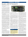
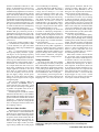
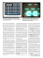
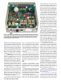
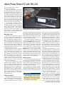
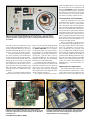
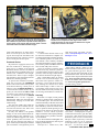
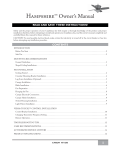
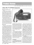
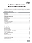
Product Review & Short Takes Columns from QST Magazine
March 2001
Product Reviews
Elecraft K-1 QRP CW Transceiver Kit
Idiom Press Rotor-EZ with RS-232
Short Takes
DX4WIN/32
Copyright © 2000 by the American Radio Relay League Inc. All rights reserved.
PRODUCT REVIEW
Elecraft K-1 QRP CW Transceiver Kit
Reviewed by Al Alvareztorres, AA1DO,
ARRL TIS Coordinator, with technical
assistance from Zack Lau, W1VT, ARRL
Senior Lab Engineer
The first radio I ever assembled was
the “Official Cub Scout Crystal Radio
Set.” The receiver was built right on the
cover of its cardboard box using pictures
of the components as a guide. That was
1951. Next, when I was around 13 years
old, I put together a slug-tuned AM radio
that I had ordered from an ad in the back
of Popular Electronics. But what I consider my first true kit building experience
took place in 1959, when I built a
Heathkit AR-3 General Coverage Receiver. From that point forward I would
hold all subsequent kits up to the
“Heathkit standard.”
As the years passed by, I assembled
some kits from other manufacturers—
Eico among them—but I always felt that
Heath provided the best instruction manuals. By the late ’80s I had successfully
completed dozens of their products, including stereos, test equipment and several transceivers. When Heath left the kit
business, I semi-retired from kit building.
So it was with some bias that I undertook the assembly of an Elecraft K1 QRP
transceiver. Several of my colleagues
have built Elecraft’s more advanced K2
HF multiband transceiver (see “Product
Review” March 2000)—and I was very
tempted to purchase one of those—but I
was concerned that a project of that magnitude might be beyond my capabilities.
After having a look at the information
that Elecraft provides on their Web site
(including, incidentally, the complete assembly and operating manual in PDF), I
decided that the K1 was a kit project that
that I should be able to handle.
Zack Lau, W1VT—our Senior Lab
Engineer (and already the proud owner
of a K2)—was anxious to give Elecraft’s
latest offering a try as well. Our K1 kits—
with sequential serial numbers—both
arrived on the same day.
What You’ll End Up With
The completed K1 is a compact dualband QRP CW transceiver with an impressive array of features. It has an
LCD display; three filter bandwidths;
RIT and XIT; AGC; an attenuator; a builtin CW keyer with two message memories; adjustable CW sidetone pitch and
volume; and an internal speaker.
The K1 will cover your choice of any
two of the 80, 40, 30, 20, 17 and 15-meter
bands.
The overall tuning range within both
of the bands is determined by the value
of a capacitor that’s installed in the VFO
circuitry. The transceiver can be set up
to tune over either an 80 or 150 kHz band
segment. The narrower span results in a
finer tuning rate. The capacitors can even
be swapped later if you end up changing
your mind!
The portion of each band covered is
established in the alignment phase. The
transceiver can be set up for from 7.000 to
7.080 MHz, or from 7.070 to 7.150 MHz
for example. (Assuming here that you’ve
chosen an overall tuning range of 80 kHz.)
Its relatively small size, rugged construction and meager appetite for dc
power (around 50 mA on receive) make
the K1 a particularly attractive choice for
portable operation—hiking and camping
for example.
The receiver is a single conversion
superhet with an IF of 4.915 MHz. It
employs a pair of NE602s—one for the
receive mixer and a second for the product detector. This design is similar to that
used in many of the other low current,
low cost QRP rigs. In spite of the limita-
Bottom Line
The Elecraft K1 raises the state
of the art for home constructed
QRP transceivers. With a PIC microprocessor running the show, this
rig delivers an operating feel and
collection of features that rivals
some contemporary commercially
constructed transceivers.
Joe Bottiglieri, AA1GW
From March 2001 QST © ARRL
tions of these simple devices, Elecraft has
managed to achieve some fairly respectable receiver performance (see Table 1).
A 4-pole variable bandwidth crystal
filter provides three receive filter bandwidths. The default settings are approximately 800, 400 and 250 Hz, but these
can be easily varied to suit your personal
preferences. The AGC, unlike the setup
used in the K2, is audio derived. It can
be switched on or off.
Audio from the receive stages is passed
through a cascaded pair of common ICs:
an LM386 and a LM380. The ’386 serves
as a preamplifier, providing lots of gain,
while the ’380 further amplifies the audio
signal—delivering lots of output. The
K1’s top-mounted internal speaker does a
good job; it’s unlikely that you’d find
yourself straining to hear this radio’s audio over the howling winds. A 1/8-inch stereo headphone jack is provided right on
the front panel—just in case.
The transmitter uses a 2SC1969 as the
RF final transistor. This rugged device—
very conservatively rated in this 5 W application—should easily be up to the task
of withstanding the VSWR “challenges”
often unintentionally encountered with
portable antenna installations.
Tuning duties are handled by a varactortuned Colpitts oscillator that generates a
VFO signal of 2.930 to 3.080 MHz. To
minimize drift, Elecraft uses double regulation on the VFO’s supply voltage and
took care to well buffer the VFO circuitry
from that of the transmitter.
Perhaps the most notable difference
between the K1 and the other QRP kit
transceivers currently on the market is its
use of microprocessor control. A significant amount of the circuitry, most of the
features and the LCD display are under
Assistant Technical Editor
the direct command of a PIC16C77. This
allows for multifunction control keys;
display flexibility; built-in test and
troubleshooting capabilities; an extensive
control and configuration menu; and CW
keyer and memory features. While most
QRP kit transceivers use simple switches,
potentiometers and analog tuning dials—
just like the commercially built amateur
transceivers produced decades ago—the
K1’s processor-based control architecture
is similar to that found in contemporary
factory assembled amateur gear.
The stylish 4-color front panel and the
modular dark gray enclosure provide a
sophisticated look and feel. The completed K1 even manages to look more like
a commercially assembled transceiver
than a few of the commercially assembled
transceivers!
Front panel controls include a large
(11/4-inch diameter) tuning knob; small
(1/ 2-inch diameter) AF gain and offset
knobs; and 6 fairly large multifunction
control keys.
The 1 × 1/ 2-inch three-digit LCD window typically displays the more “significant digits” of the operating frequency
(more on this later), but these same LCD
segments are also employed to indicate a
wide range of additional data. The information appears as either number digits or
the familiar—but somewhat truncated—
set of alpha characters that can be rendered using combinations of the seven
straight segments available in the usual
LCD “figure 8” segment pattern. In addition to the frequency, the LCD can display the supply voltage, the RF power
output, the various menu titles and their
settings, and a 6-segment relative signal
strength bargraph.
The rear panel supports a BNC antenna connector, the ON/ OFF switch, a
coaxial-style dc power jack and a 1/8-inch
stereo jack for connecting a straight key
or paddles. The paddle sense can be reversed using a menu setting.
Available options include an internal
automatic antenna tuner, a noise blanker
and a neat little tilt-up stand. You can even
purchase additional 2-band filter modules
separately—’though the band filter
mounting and connector arrangements
were not designed with incessant module swapping in mind.
seem considerably less daunting.
My first impression of the K1 Owner’s
Manual was very favorable. The booklet
is large, has over ninety 81/2 × 11-inch
pages in a landscape format, and is spiral bound—allowing it to lie flat on the
workbench. It includes part lists and layouts, block diagrams, circuit details and
schematics, an extensive section on
troubleshooting, the operating instructions and even a “Quick Reference” page.
The type is large and all of the illustrations and photographs are clear.
The first several pages are devoted to
a tutorial on identifying components, a
list of the tools that you’ll need for assembly, and the all-important lessons on
soldering and de-soldering. You’ll also
find a section with detailed instructions
on the proper way to install transistors,
ICs and capacitors.
Besides the usual basic electronics
hand tools, the only other equipment required to complete this kit is a digital
multimeter. The K1 features built-in test
capabilities that become available as you
progress through the assembly stages.
These include a wattmeter, a frequency
counter and a battery voltage monitor.
Taking Attendance
Of course the first task when building
any kit is taking an inventory of the parts.
Here, Elecraft has managed to outdo even
Heath. “Appendix A,” the parts list, contains
actual photographs (Heath typically used
line drawings) of every component type to
aid in identification. This is a real plus.
The inventory process begins with a
general breakdown of the contents of the
shipping box—the circuit boards, the
cabinet panels, the knobs, and the various bags of parts (“Bag, Filter,” “Bag,
Front Panel,” “Bag, RF Board,” etc). It
then goes on to separate sub-inventories
of the contents of each of the bags.
The specific parts provided for the filter board will, of course, vary according
to which two bands you have chosen.
Elecraft suggests that you begin this stage
of the inventory process by crossing off
the parts that are listed for the bands you
didn’t order. They then recommend that
you use two different color pens (one for
each band) for checking off the components for those that you did. (These folks
have thought of everything.)
I was very impressed with the quality
of the PC boards. They are solder masked
and have plated-through holes, making
soldering easier on the relatively crowded
boards. The silk screening on both sides
of the boards is excellent. The component
outlines are clear and the legends are well
placed. I found no ambiguities as to
where a specific component was to be
installed—a problem that I’ve encountered building some other kits.
Most of the resistors used in this kit
are “presorted.” They are taped together
in strips in the order in which they are to
be installed. This is a real convenience!
During the inventory process I discovered that I was missing a 0.1 µF monolithic capacitor. In all fairness, there was
an errata sheet packed with the kit explaining that the value of a capacitor had
been changed. My kit erroneously contained the old value—I can see how that
might happen. In any event, I called
Elecraft the next morning and had the
correct part in hand a few days later.
What You’ll Start Out With
The K1 kit arrives in a surprisingly flat
box. The cabinet is constructed from five
panels that are fastened together as the
kit is assembled. Most of the components,
except this sheet metal and the main PC
board, come packaged in separate, labeled, zip-lock bags. Working with the
contents of one bag at a time (even during inventory) makes the overall project
The Elecraft K1 kit as delivered. The majority of the components are presorted into
plastic bags, making the inventory and assembly processes considerably more
manageable.
From March 2001 QST © ARRL
Table 1
Elecraft K1, serial number 00108
Manufacturer’s Claimed Specifications
Measured in the ARRL Lab
Frequency coverage: Receive and transmit, any 80 or 150 kHz segment of
any two bands covered; 3.5-3.65; 7-7.3; 10-10.15; 14-14.35;
18.068-18.168; 21-21.45 MHz.1
Receive and transmit, as specified.
Modes of operation: CW.
As specified.
Power requirement: 9-15 V dc, receive, 50 mA (no signal);
transmit, 0.8 A, at 13.8 V.
Receive, 57 mA (maximum volume, no signal);
transmit, 0.75 A (maximum), tested at 13.8 V.
Size (hwd): 2.4×5.2×7.1 inches; weight, 1.4 lb.
Receiver
Receiver Dynamic Testing
CW sensitivity: 10-dB S/N, 0.15 µV.
Noise floor (MDS), 500 Hz filter:2
7 MHz
–129 dBm
14 MHz
–129 dBm
Blocking dynamic range: Not specified.
Blocking dynamic range:
7 MHz
107 dB
14 MHz
107 dB
Two-tone, third-order IMD dynamic range: Not specified.
Two-tone, third-order IMD dynamic range:
7 MHz
87 dB
14 MHz
86 dB
Third-order input intercept point: Not specified.
7 MHz
14 MHz
Second-order intercept point: Not specified.
14 MHz, +75 dBm.
S-meter sensitivity: Not specified.
Maximum indication: 490 µV.3
Receiver audio output: 1 W into 8 Ω, THD not specified.
1.1 W at 0.3% THD into 8 Ω4.
IF/audio response: Not specified.
Range at –6 dB points, (bandwidth):
CW-N: 412-847 Hz (435 Hz)
IF rejection: Not specified.
87 dB.
Image rejection: Not specified.
69 dB.
Transmitter
Transmitter Dynamic Testing
Power output: 0-5 W.
Typically 0.3-5 W.
+1.5 dBm
+0.0 dBm
Spurious-signal and harmonic suppression: 40 dB.
43 dB. Meets FCC requirements for spectral purity.
CW keyer speed range: 8 to 50 WPM.
8 to 49 WPM.
CW keying characteristics: Not specified.
See Figure 2.
Composite transmitted noise: Not specified
See Figure 1.
All dynamic range measurements are taken at the ARRL Lab standard spacing of 20 kHz.
1
The exact operating range is determined by the builder.
The actual filter bandwidth is somewhat narrower.
3
With six LCD segments lit (builder adjustable).
4
At maximum volume.
2
The Assembly Process
The Filter Board (which supports the
components for your two chosen bands)
is assembled first. Next up is the Front
Panel Board (perhaps this is a little reward to let you see what the radio is actually going to look like?). Finally the RF
Board, the largest and most densely populated of the three, is constructed in two
“sessions”—the receiver section is built
up first and then the transmitter components are added. As each portion is completed, resistance and voltage checks (if
applicable) are made.
The K1, much like the K2, is a modular design that uses virtually no point-toFrom March 2001 QST © ARRL
point wiring. The controls, the display
and all of the external connectors are
mounted right on the PC boards. The only
exceptions are a plug-in cable that connects the internal speaker and an RG-174
jumper on the underside of the RF Board.
The Front Panel Board connects to the
RF Board through a 20-pin header. The
Filter Board is piggybacked onto the rear
portion of the RF Board through three 8pin connectors and held in place with
three screws with lock washers.
The K1 assembly instructions are superb in both layout and clarity. They
guide you through the assembly and tests
on each section before you proceed to the
next. With Heathkit’s documentation—as
I remember it—your actual resistance and
voltage measurements would sometimes
vary from the “nominal” values printed
in the manual. You would then have to
decide for yourself if the measurements
you were seeing were close enough—and
then continue on faith alone. In the K1
manual, resistance and voltage ranges are
provided. There are also plenty of warnings and special instructions to insure that
you have installed specific components
correctly. By the time you reach the final
alignment stages, you just know the radio is going to work!
Winding the toroids used in the K1
–60
–70
Reference Level: - 60 dBc/Hz
Vertical Scale: dBc/Hz
–80
–90
–100
–110
–120
–130
–140
2
4
6
8
10
12
14
16
18
20
Frequency Sweep: 2 to 22 kHz from Carrier
22
Figure 1—Worst-case spectral display of the Elecraft K1
transmitter output during composite-noise testing. Power
output is 5 W at 7.020 MHz. The carrier, off the left edge of the
plot, is not shown. This plot shows composite transmitted noise
2 to 22 kHz from the carrier.
turned out to be easier than I had expected.
This is an aspect of kit building that I
previously had little experience with—
Heath would typically provide components such as these as a prefabricated subassembly. I must admit that I felt some
initial pangs of “toroid-a-phobia.”
After starting the first one I quickly
realized that it was somewhat like sewing—only easier. No sharp needle! There
are a total of 10 toroids that must be
wound, and only the very last one presented any challenge whatsoever. T4 on
the RF board requires a bifilar winding,
so a twisted pair of wires has to be “sewn”
through the core. This took me two tries
to get right—but with only 5 turns, it required only a couple of minutes to rework. The toroid winding illustrations
and the text descriptions in the manual
are excellent.
“Alignment and Test” procedures are
preformed in two parts—once after the
receiver is completed and later when the
transmitter components have been added
to the RF Board. Some adjustments involve activating the on-board test features. These are enabled by pressing combinations of the front panel buttons.
After the second alignment and test
phase has been completed, you’re nearly
there. Install the internal speaker, bolt on
the top cover, stick on the rubber feet, slap
on the serial number tag and… it’s time
to play radio!
The total assembly time for me was a
little over 30 hours. I typically worked in
2 to 3 hour sessions and put the radio together over the course of a couple of
weeks. Zack managed to assemble his K1
in just 18 hours.
Figure 2—CW keying waveform for the Elecraft K1 showing the
first two dits in full-break-in (QSK) mode using external keying.
Equivalent keying speed is 60 WPM. The upper trace is the
actual key closure; the lower trace is the RF envelope.
Horizontal divisions are 10 ms. The transceiver was being
operated at 5 W output at 14.020 MHz.
Although the instruction manual is
excellent and the builder support offered
by both Elecraft and the participants on
their rapidly growing e-mail reflector
(currently boasting over 1000 members)
is approaching the level of “legendary,”
I’d hesitate to describe the K1 as a suitable project for a beginner.
Heathkit probably would have rated a
project such as this at least a “skill level
2” (their scale ran from 1 to 3). But if
you’ve got decent PC board soldering
skills, reasonably good vision and dexterity—and patience—you shouldn’t run
into any major problems successfully
completing this kit. And yes, building a
K1 is the perfect “dress rehearsal” for the
assembly of a K2. The construction skills
required are approximately equivalent.
Learning the Ropes
The six keys on the front panel of the
K1 all perform multiple functions. White
legends above each key indicate its primary assignment. These are accessed
with a light tap (or taps) of the key. The
secondary control function legends appear in yellow below each key. Pressing
and holding a key typically evokes these.
Switching the power on—or tapping
the BAND/DISPLAY key—will result in a
display of the current band and operating frequency. Since the LCD is only capable of indicating three digits at a time,
it does so in stages. If the operating frequency is set to 7139.5 kHz for example,
the display will first show 7, then 139,
and then 39.5 . Two quick taps of the
BAND /DISPLAY key will toggle the radio
between bands.
Pressing and holding this same key
allows you to change the information
that’s shown when the transceiver is in
the receive mode. You can choose to view
the frequency, an S meter bargraph or the
dc supply voltage. Turning the VFO knob
while in the S-meter mode will automatically bring up the frequency display.
The MENU /EDIT key is used to enter
the menu mode and to edit the settings of
the various parameters. While in the
menu, the WPM+/XFIL and WPM-/ ATTN
keys are used to scroll up and down
through the 16 alpha-tagged selections.
Settings are altered by pressing and holding the MENU/EDIT key and then tapping
the WPM+/XFIL or WPM- / ATTN keys to
step through the available choices.
An RIT/ XIT [PFn] key resides in the
lower center portion of front panel. A
quick tap will activate the receive incremental tuning. Pressing and holding this
key briefly will evoke the transmit incremental tuning. When either is enabled, a
flashing decimal point will appear in the
LCD display. The transmit and receive
frequencies can be offset—using a rotary
control—by up to +/− 3 kHz.
In addition to the flashing decimal point,
a bi-color LED—located above the main
tuning knob—lights green when the RIT is
on, or orange when the XIT is on. A second
yellow LED, located just to its right, illuminates when the attenuator is on. A menu
setting allows you to disable both of these
LEDs to conserve battery power.
The XIT assignment of the RIT/ XIT
[PFn] key can be reprogrammed to serve
as a shortcut key to any one of the K1’s
menu selections.
The WPM+/XFIL and the WPM-/ATTN
keys—along with a MSG/REC key—are
From March 2001 QST © ARRL
Figure 3—An internal view of W1VT’s K1. The Front Panel Board plugs into the main
board along its front edge. The Filter Board, which determines the two bands covered
by the transceiver, is towards the rear of the enclosure (the forground in this photo).
It’s positioned above the RF Board and connects to it through three 8-pin headers.
Three small screws secure it in place.
arranged in a column along the right edge
of the front panel. In addition to the menu
setting operations already mentioned,
these keys are also used to vary the speed
of the internal CW keyer, to step through
the three filter bandwidth settings and to
control a 14-dB attenuator. Pressing both
keys simultaneously will lock the transmitter on—a handy feature for making
antenna tuner adjustments, for example.
The MSG/REC key is used to record
and play the contents of the two CW
memories. Each memory provides 90
bytes of EEPROM storage—the programmed messages will not be lost when
the transceiver is shut off. An “Auto-Repeat” feature allows either message to be
continuously retransmitted after a menuselected delay interval of from 0 and 255
seconds. This would be convenient for
beacon applications, for contesting or for
repeatedly calling CQ on a “quiet” band.
Advanced features are controlled
through the menu. These include the RF
power output level; the AGC (on or off);
the QSK delay; the sidetone volume and
pitch; the key type (straight key or
paddles); the paddle sense; and the iambic mode. Curtis A or Super CMOS Keyer
III B emulation is supported.
The rotary controls and the buttons on
the K1 all have a decent feel to them, but
From March 2001 QST © ARRL
there is a noticeable amount of lateral
play in the shafts of the potentiometers
used for the volume and offset controls.
This is undoubtedly a consequence of
using board-mounted potentiometers, but
it detracts somewhat—at least cosmetically—from the otherwise rugged appearance of this transceiver. Nylon bushings
might help.
The main tuning knob controls the
varactor-based VFO through a multi-turn
potentiometer. Vigorous cranking generates a mechanical sound that resembles
that made by a guitar player’s fingers sliding along the strings from fret to fret. The
tuning action is smooth and solid, however.
QRV!
The K1—at least initially—is more
complicated to operate than the typical
QRP kit transceiver, but you’ll quickly
warm up to the nice selection of advanced
features.
The digital display is particularly handy.
If you should accidentally bump the main
tuning knob in the middle of a QSO, it’s
easy to tune the radio precisely back to the
desired frequency. This can be a problem
with analog tuning arrangements.
Since the K1 employs a frequency
counter to measure the actual frequency
of the VFO—and uses that information
to drive the display—you can easily compensate for any drift that might occur due
to warm up periods, temperature extremes or wide variations in supply voltage. This simply involves making small
adjustments of the main tuning knob to
keep the displayed frequency constant.
The selectable filter bandwidths are
another big plus. The wider settings are
convenient when tuning around looking
for activity or for listening for answers
to your CQs. Once you’ve identified a
target signal, you can switch to a narrower filter setting to reduce QRM.
The RIT arrangement on the K1 is
nicely designed. The ability to switch it
on and off makes it particularly useful
for contesting. You can leave the filter
bandwidth set at the narrower settings
and not have to worry about re-matching your transmit and receive frequencies between contacts. This can be tricky
with a strictly rotary control.
XIT is just icing on the cake! This
added capability is especially handy for
chasing DX in a pileup. First, tune to his
frequency, then tap the RIT/XIT [PFn] key
to activate the RIT, and use it to search
for his listening frequency (simply hunt
for the station in the pileup exchanging
reports with him). When you’ve located
one, hold the RIT/XIT [PFn] key down
briefly and you’ll be listening on his
transmit frequency and all set up to transmit on his listening frequency!
I’ve had the K1 set up at my home station and used it to make several domestic
contacts using my 80-meter dipole and an
antenna tuner. Zack has worked a fair
number of DX and domestic contacts on
a variety of bands on his. (We purchased
enough band modules to cover all the
possibilities and have been swapping
them off between us). Rick Lindquist,
N1RL, took my rig home for a weekend
and ended up playing around a bit in the
North American QSO Party. He reported
that the receiver held up reasonably well
even under fairly busy band conditions
and that he had no trouble at all participating with “just” 5 W.
For me, building the Elecraft K1 was
sufficiently challenging to make things
interesting—yet still simple enough to
keep it fun. The completed K1 delivers a
collection of features and a measure of
performance that’s a cut above those of
the average QRP kit transceiver.
Manufacturer: Elecraft; PO Box 69,
Aptos, CA 95001; 831-662-8345; fax
831-662-0830; [email protected];
www.elecraft.com.
Price: Elecraft K1 two-band QRP
CW transceiver kit, $269; KFL1 additional two-band modules $59; KNB1
noise blanker, $29; KAT1 antenna tuning
unit, $89; KTSI wide range tilt stand, $35.
Idiom Press Rotor-EZ with RS-232
Reviewed by Ward Silver, NØAX
QST Contributing Editor
Of all of the operations in the average
ham shack that have been interfaced to a
PC over the last few years, one of the last
holdouts has been antenna rotation control. While computer-controlled rotator
systems and substitute control boxes have
been readily available for quite some
time, they have historically been rather
pricey. Enter Idiom Press’s Rotor-EZ with
RS-232 controller kit for the Ham-II, III
and IV, and Tailtwister control boxes.
A second nearly identical version of
this kit—lacking the components required for computer interface capabilities
but providing all of the other enhanced
system control features—is also offered.
The parts needed to add computer control can also be ordered separately and
installed on the circuit board of the more
basic version at a later time.
What Does It Do?
The Rotor-EZ (pronounced “RotorEasy”) is a small circuit board kit that can
be installed inside the control boxes of
any of the Ham-M or Tailtwister rotators
that use analog meters and the three-lever control arrangement. The device employs a microprocessor that works with
the existing control box’s electronics,
switches and meter to add both hands-off
point-and-go operation and more “intelligent” rotator motor control.
Rotor-EZ smartens up the controller
command operations with an automatic
five second brake delay, electronic end
points (to avoid the mechanical lock up
that sometimes occurs when the motor
runs into its end stops), an “Unstick” routine for Tailtwisters and jam protection.
In other words, it takes care of all of the
things an operator is supposed to do to
reduce wear and tear on a rotator and
tower, only automatically.
There is also a ninety-degree offset
indication feature available—perfect for
those who have additional directional
antennas installed at right-angles to the
main antenna. (This is a common configuration that’s used to reduce interaction between closely spaced antennas.)
Rotor-EZ is even smart enough to put up
with—to some extent—the “dead spots”
that sometimes develop in worn indicator potentiometers.
How Does It Work?
The brain of the Rotor-EZ is a Microchip Technologies PIC16C73 microprocessor. It responds to your manual or
computer commands and drives separate
Hidden inside this ordinary-looking rotator control box is a new product that enhances
its operation and expands its capabilities.
relays that control the brake solenoid and
the motor in the rotator. The processor
uses an analog-to-digital converter to read
the position of the rotator motor’s direction potentiometer and that of the control box’s calibration control.
Once Rotor-EZ has been installed, the
control box’s existing front panelmounted CALIBRATE knob becomes a goto bearing set point control—Idiom Press
refers to this as “Auto-Point.” The meter
is driven by the processor’s outputs and
serves double duty—it indicates the targeted direction when using the CALIBRATE knob to set the desired antenna
bearing, and the actual direction as the
antenna turns towards and reaches its new
heading. The processor also controls four
LED indicators and uses them to show
what the system is doing, the progress of
rotation and any error conditions.
Building the Kit
I received my Rotor-EZ kit and immediately got down to business. The patient?
My Tailtwister control box. This is the
rotator control located farthest from my
operating position and the one that takes
the longest stretch to operate.
My Tailtwister frequently “sticks”
when the brake wedge doesn’t fully disengage as rotation begins (this is a common idiosyncracy with the Tailtwisters).
Bottom Line
Rotor-EZ adds set and go convenience, “intelligent” motor control,
added features and optional computer
controllability to the popular Ham-M
and Tailtwister rotator systems.
The usual cure is a short manual pulse in
the opposite direction before beginning
a rotation. Rotor-EZ performs this automatically, so I was definitely anxious to
take advantage of that feature. I disconnected the rotator control box, pulled it
out of the shack and dragged it—kicking
and screaming—off to my “laboratory.”
The Rotor-EZ kit comes with a fair
number of parts (see Figure 4). They’re
all packed onto a small circuit board
that’s designed to be mounted right on the
studs of the meter in the control box (see
Figure 5).
I am an experienced builder, so it only
took about a half-hour to stuff and solder
the board, even though I took the time to
check off every step and double-check the
resistor values. I recommend that you
take your time during the assembly phase
and be careful to do the job right—it
would likely be very difficult to troubleshoot the board after it’s been installed.
I had to drill a hole for one of the LED
indicators in the front panel of my box—
my unit originally had only three LEDs.
Depending on your particular model and
version of the control box, it may be necessary to drill additional holes for the other
LEDs, and possibly a hole in the back
panel to pass the computer control cable
through as well. When drilling, it’s a good
idea to use masking tape on the inside of
the box to catch any stray chips.
Once you’ve completed the circuit
board, secured it to the meter, wired up
the four LEDs and rewired the CALIBRATE
control pot, you can run a “Pretest.” If
everything checks out, you can continue
integrating the unit into the control box.
As I removed wires in the existing
control circuitry, I took pains to record
From March 2001 QST © ARRL
tions and applied power. Success! All of
the smoke stayed in the components and
the rotary CALIBRATE control and switches
all appeared to behave properly. I followed
the calibration instructions and had the
rotator system back in operation within
four hours of initially opening the case.
The Instructions and User Manual
Figure 4—The Rotor-EZ with RS-232 kit as delivered. The 33/8 × 33/16-inch doublesided circuit board is solder masked and silk screened with component outlines
and parts numbers. Everything you’ll need—including hookup wire and wire ties—
is included.
the color of each wire and where it went
in the original configuration. This is especially important should you decide to
assemble and install the kit over several
sessions—don’t rely on memory alone!
A couple of warnings are in order here.
The wires originally used within these
control boxes are typically solid conductor and the insulation on them has a low
melting point. If you linger too long with
the soldering iron you’ll melt the insulation off the wires. Most of the wires in
my control box were long enough to snip
them off at their connection points and
strip off a little more insulation for reattachment.
There is a common modification that
has been made to many of these control
boxes over the years that keeps the brake
off for a few seconds after you let go of
the BRAKE RELEASE lever (see Figure
7). Rotor-EZ takes care of all brake delay operations, so if your box has had this
change made, you’ll want to begin by reversing this—and any other—user-installed modifications. The instructions
naturally assume that you are installing
Rotor-EZ in an unmodified unit.
I proceeded carefully through the process of interfacing the new brain to the
remaining control box circuitry. There are
quite a few wires involved. Take your
time and pay close attention to properly
dressing the leads. The completed installation is shown in Figure 8.
I then double-checked all my connec-
Figure 5—The assembled Rotor-EZ circuit board ready for
installation in the rotator control box. The vacant 28-pin socket
in the lower right hand corner of the board is for the PIC16C73
microprocessor.
From March 2001 QST © ARRL
I found the instructions to be clear and
straightforward, but there are no drawings—text only. When I asked Idiom
Press about this, they told me that they
have identified (among unmodified controllers) five different meter movements
and at least three significantly different
component layouts. There are also minor
variations among these. Early boxes employed separate components where later
boxes used printed circuit boards. Even
then, there are at least two different versions of PC board models.
Since it would take a significant number of drawings or photographs to cover
all of the possible variations, the instructions rely completely on text descriptions—and they do a very good job. I was
able to complete the installation phase
successfully by carefully following each
step. Providing a table for the builder to
jot down notes detailing where the original wires are routed would be a helpful
addition, but scrap paper will suffice. On
a scale of 0 (totally confounding) to 10
(Heathkit-like), I would rate these instructions a 7.
Opportunities for Improvement
The component labeling on Rotor-EZ’s
PC board could have been clearer—some
of the silk-screened text designators are
obscured or overlay a solder pad. Also, the
Figure 6—My Tailtwister control box awaits “brain surgery.” The
Rotor-EZ circuit board will be replacing the original one that’s
mounted on the meter studs (located just to the right of the
large transformer in this photograph).
Figure 7—The electrolytic capacitors, the relay (the white
plastic cube) and the diodes in this photo are a modification
that I added a few years back to provide a brake delay. This—
and any other circuit changes that have been made—must be
eliminated before Rotor-EZ installation begins.
solder pads themselves are rather small.
Since I received my kit, the silk screening has been improved and Idiom Press
has indicated that they intend to increase
the size of the pads at some point.
Functional Review
My Rotor-EZ equipped control box
has been trouble-free. Although I live
quite close to a number of 50 kW AM
Broadcast stations, I haven’t encountered
any RF interference problems either to or
from the unit. Calibration was straightforward and it didn’t require multiple
trips outside to verify which direction the
antenna was actually pointing.
To operate the modified controller,
what was previously the CALIBRATE
knob is now used to set the meter pointer
to the desired bearing. A short press of
what was once the BRAKE RELEASE lever then initiates antenna rotation. If you
prefer, you can still use the CW and CCW
(clockwise and counterclockwise) levers—in combination with the BRAKE
RELEASE lever—in the “original”
manual mode. Either way, the brake will
automatically reengage 5 seconds after
rotation stops.
The direction LEDs show what the
unit is doing. In case of trouble, the status LED will blink or the meter will
wiggle to alert the operator.
A really neat feature is the gradual
change of color of the multicolored status LED. When a turn command is executed, the LED first appears red. As the
rotator gradually turns toward the set
point, the color changes from orange to
green. I found myself turning the antenna
just to watch the cool light show put on
Figure 8—The Tailtwister control box with the Rotor-EZ system
installed. Close comparisons with Figure 6 will reveal a
significant number of new connections between the original
components and their new master.
by the LED!
I connected the RS-232 cable to my
PC and exercised the unit’s computer control functions through a terminal program.
The command protocol is listed in the
user manual. I will eventually command
the rotator through my logging software.
The software protocol for Rotor-EZ is the
same as that of Hy-Gain’s DCU-1.
I have not tried the Overshoot option
(which allows big antenna systems to
coast through the last three degrees into
position) or the 90-degree offset feature
(for antennas mounted at right angles).
Have I found Rotor-EZ to be useful?
You bet! I can set, start and forget—just
like on the more expensive rotator control boxes. I never find myself accidentally holding the control levers down
while brake wedge is stuck. I now even
occasionally catch myself trying to use
the Auto-Point mode on my currently (but
not for long) stock Ham-IV control box.
1025, Geyserville, CA 95441; 707-4311286; [email protected]; www.
idiompress.com.
FEEDBACK
◊ Sam Ulbing, N4UAU, author of “The
World’s Smallest Code-Practice Oscillator,” QST, Feb 2001, pp 39-41, has provided a part-placement diagram for his
homemade PC board. You can download
a picture of the diagram from Sam’s Web
page http://n4uautoo.home.sprynet.
com and as ULBPIC.ZIP from the ARRL
site www.arrl.org/files/qst-binaries/.—
tnx Sam Ulbing, N4UAU
Summary
Rotor-EZ is a simple, useful product
that fills a common need in ham shacks
at a reasonable price. You sacrifice none
of the functionality of the old control unit
by installing it. The consistent and reliable method by which the rotator motor
will be operated should prolong its life
and save wear and tear on the tower and
antennas. I—for one—am for any station
improvements that will help keep Murphy
at bay. Rotor-EZ is a product I can heartily recommend.
Price: Rotor-EZ kit including RS-232,
$129.95; Rotor-EZ basic kit, $99.95 (plus
shipping and handling).
Manufacturer: Idiom Press, Box
◊ Please refer to Ron Stone, KA3J, “The
UniCounter—A Multipurpose Frequency
Counter/Electronic Dial,” QST, Dec 2000,
p 34, Figure 1. Ron advises he incorrectly
showed U1 pins 12 and 13 connected to
DS1 pins 1 and 2, respectively. Correct the
schematic to show U1 pin 12 connected
to DS1 pin2 and U1 pin 13 connected to
DS1 pin1.— tnx Ron Stone, KA3J
From March 2001 QST © ARRL
SHORT TAKES
DX4WIN/32
DX4WIN/32 from Rapidan Data Systems is a software package that adds new meaning to the word “multifaceted.” It does
all standard logging tasks such as award tracking (DXCC,
WAS, WAZ, IOTA, VUCC, TenTen and more) and label printing. It even includes features that are quickly becoming standards in the rest of the software logging world such as rig control, multiple log access and so on. But DX4WIN/32 adds a
number of abilities that place it in front of the pack…
• PSK31 operation with your PC soundcard. You can send
and receive PSK31 within DX4WIN/32—and log your QSOs
in DX4WIN/32 as you go.
• CW keyboard.
• World map display with grayline.
• Antenna rotator interfaces.
• CD-ROM database support.
• A contest mode with dupe checking and incrementing
serial numbers.
Test Drive
DX4WIN/32 in the PSK31 mode. Individual signals are
displayed in the waterfall portion of the window.
My opportunity to try DX4WIN/32 came early last January.
I had just finished working the ARRL RTTY Roundup using
WriteLog software. Could DX4WIN/32 digest my WriteLog
file? I entered WriteLog and saved my RTTY Roundup file in
ADIF format, a standard for database exchange. Then, I opened
DX4WIN/32, started a new log labeled WB8IMYRTTY, and
then used the Import function to read the WriteLog ADIF file.
The data flowed into DX4WIN/32 effortlessly, and I received
a report of the results. Now I could page through the log, sort
the QSOs as I pleased and print labels. I jumped to the awardtracking section to see how many entities I had bagged for my
RTTY DXCC.
DX4WIN/32’s world map function is intriguing. With the map
window open, you can see the path to the DX station in question and the distance in miles or kilometers. You also have your
choice of several map projections (some of which I’d never heard
of!). As you drag your mouse pointer over the map, the countries are highlighted along with their call sign prefixes.
Speaking of the map, DX4WIN/32 can monitor spots from
radio PacketClusters, Internet “telnet” clusters or Webclusters.
DX4WIN/32 will integrate all of the incoming spots into a
single window, announce them verbally—and show the targets on the world map (with bearings from your position). DX
hunting doesn’t get much better than this.
The PSK31 module performed admirably. It uses the panoramic approach popularized by DigiPan. You see a waterfall
display below the text windows and “tuning in” a signal is as
easy as clicking your mouse. DX4WIN/32’s PSK31 performance was outstanding.
My RTTY Roundup log sorted by date.
you don’t have a log open, you can leave DX4WIN/32 running
in the background on your Windows desktop (it appears as a
narrow bar across the top).
DX4WIN/32 isn’t a processor hog. It will run on just about
any Pentium PC under Windows 95/98/ME. DX4WIN/32 also
conserves hard drive space; 15,000 QSOs can be stored in less
than 1 Mbyte.
There are certainly less expensive logging programs on the
market, but if you want to turn your station computer into a
true Amateur Radio nerve center, DX4WIN/32 will leave you
happy with your investment!
Manufacturer: Rapidan Data Systems, PO Box 418, Locust
Grove, VA 22508; tel 540-785-2669; www.dx4win.com/. $89.95
plus $6.95 shipping and handling to the US and Canada; $11
elsewhere. Virginia residents add 4.5% sales tax.
Ease of Use
Despite its complexity, DX4WIN/32 is relatively simple from
a user standpoint. You can select “user levels” from beginner to
expert as you become accustomed to the software. It’s obvious
that Rapidan Data Systems designed DX4WIN/32 to be as intuitive as possible. I’m not an experienced user of logging software, yet I was able to navigate my way around DX4WIN/32
without turning to the printed manual or the help files. When
Steve Ford, WB8IMY
QST Managing Editor
March 2001
105