1
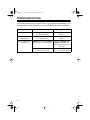
49-208A.fm Page 1 Wednesday, August 18, 1999 3:15 PM
Cat. No. 49-208A
OWNER’S MANUAL
Please read before using this equipment.
180° Passive Infrared
Motion Sensor
49-208A.fm Page 2 Wednesday, August 18, 1999 3:15 PM
FEATURES
Your RadioShack 180° Passive Infrared Motion Sensor is designed for use
with security alarm systems, such as
those sold by your local RadioShack
store. Passive means that the sensor
detects changes in heat within its coverage area without a transmitter.
When an intruder enters a protected
area, the sensor detects the temperature change and triggers the system’s
alarm. You can use the motion sensor
to help protect any area of your home
while you are at home or away.
Selectable Alarm N.C./N.O. Output
— lets you select either N.C. (Normally Closed) or N.O. (Normally Open)
alarm output to match your alarm system.
Adjustable Angle Scale — lets you
adjust the sensor to a variety of angles
for the most effective coverage.
Dual-Element Low-Noise Pyroelectric Detector — extends the sensor’s
coverage area and reduces false
alarms.
Its features include:
Four Interchangeable Lenses (Wide
Angle, Long Distance, Pet, and Curtain) — let you select the lens that
best suits your needs.
Ultra High Level RFI/EMI Protection
— prevents interference from radio
frequencies between 136 and 1,000
MHz.
Temperature Compensation Circuit
— helps reduce false alarms.
Tamper Protection Circuit — triggers the alarm system when someone
tampers with the sensor.
Compact Design — makes the sensor easy to install in almost any indoor
location.
Walk Test Indicator — makes testing
the sensor’s coverage range easy.
READ THIS BEFORE
INSTALLATION
Before you install the motion sensor,
read the entire “Installation” section.
Decide where to mount the motion
sensor and where to route the wires.
Programmable Pulse Count — lets
you set the number of zones the intruder must cross before the sensor
triggers the alarm.
© 1997, 1998 Tandy Corporation.
All Rights Reserved.
RadioShack is a registered trademark used by Tandy Corporation.
2
49-208A.fm Page 3 Wednesday, August 18, 1999 3:15 PM
INSTALLATION
Notes about your motion sensor:
• This motion sensor is for indoor
use only.
• The sensor does not have an
internal alarm sounding device or
power supply. It is designed for
use with a UL-listed central alarm
panel system that provides a minimum of 4 hours of standby power.
You can mount the sensor on the ceiling, a wall or any flat surface.
For reliable operation, choose a location where the sensor faces a solid
surface (such as a wall or ceiling) to
use as a steady temperature reference. If an intruder passes between
the sensor and the surface, the sensor
detects the temperature change.
• The sensor requires 9- to 16-volt
DC power at 25 milliamps. If your
alarm system’s terminals do not
provide this power, you need an
additional power supply. Your
local RadioShack store sells a
wide variety of suitable alarm systems and power supplies.
This sensor is more sensitive to movement across its zone and less sensitive to movement directly toward or
away from the zone, so choose a
mounting location (such as a hallway
wall) where an intruder must walk
across the protected zone.
• The sensor’s operating temperature is 32 to 104°F (0 to 40° C).
When you choose the sensor’s mounting location, avoid locations where:
• If you use this sensor with a multizone alarm system, you can turn
off the zone where the sensor is
and leave the alarm system’s
other zones on. This lets you arm
your system and walk through the
zone where the sensor is without
triggering the alarm.
• Sunlight shines directly on the
sensor
CHOOSING A
MOUNTING LOCATION
Important: Do not mount the sensor
until after you wire it and check the
connections.
• The sensor will be exposed to
humidity or rain
• Any opening (such as a vent, window, or door) constantly exposes
the sensor to outside elements
• Sources of heat (such as space
heaters, radiators, exposed light
bulbs, fireplaces, or refrigerators)
are in or near the protected zone
• Strong drafts of air (such as from
a central heating vent or an air
conditioner) hit the sensor
• The sensor is aimed at an exterior
metal wall
3
49-208A.fm Page 4 Wednesday, August 18, 1999 3:15 PM
Notes:
• The sensor’s ability to detect temperature
changes
decreases
when the reference surface and
an intruder’s body are almost the
same temperature.
• The sensor must be mounted at
least 6.6 feet (2 meters) above the
floor, except when using the pet
lens (see “Selecting the Lens”).
SELECTING THE LENS
accidental triggering by curtains
that are blowing.
Use this table to select the proper lens
for the coverage you need.
Lens No.
1
Type
Wide Angle
Mounting
Height
6.6 Feet
(2 Meters)
Zone’s
Coverage
1st Zone
110°
2nd Zone
180°
The sensor has four different lenses. It
comes with the wide angle lens installed. If you decide to use another
lens, see “Replacing the Lens.’’
Notes:
• The lens number is marked on the
tab of each lens.
• The wide angle and long distance
lens sets each contain two lenses,
one for long distances and the
other for shorter distances.
• The pet lens does not detect
movement from floor level to
about 18 inches off the floor
(when mounted at the height
specified in the table). Use it to
prevent accidental triggering by
small animals.
• The curtain lens with the reflecting
mirror does not detect movement
to one side, so you can avoid
4
Lens No.
Type
Mounting
Height
Zone’s
Coverage
2
Long Distance
6.6 Feet
(2 Meters)
1st Zone
20°
2nd Zone
110°
49-208A.fm Page 5 Wednesday, August 18, 1999 3:15 PM
Lens No.
Replacing the Lens
3
Type
Pet
Mounting
Height
4.3 Feet
(1.3 Meters)
Zone’s
Coverage
110°
1. Use a Phillips screwdriver to
loosen the screw on the sensor’s
front cover, then lift off the cover.
Illustration
2. Use your finger to gently pry out
the corner of the lens frame and
the lens, then remove both from
the cover.
Lens No.
Type
Mounting
Height
Zone’s
Coverage
4
Curtain
6.6 Feet
(2 Meters)
Without
Mirror
20°
With
Mirror
10°
Illustration
3. Install the selected lens with the
smooth side out. Align its tab with
the upper recess on the cover’s
window, then gently push in the
sides of the lens to snap it into
place.
Illustration
5
49-208A.fm Page 6 Wednesday, August 18, 1999 3:15 PM
4. Push in on the lens frame to snap
it into place.
Illustration
Using the Curtain Lens
1. Use a Phillips screwdriver to
remove the screw from the printed
circuit board (PCB), then lift out
the PCB.
2. Use pliers to squeeze together the
two tabs on the back of the PCB,
then gently lift the mirror from the
PCB.
Illustration of mirror removal
The reflecting mirror gives the sensor
a narrower coverage area. You can
use the curtain lens with or without the
reflecting mirror.
Curtain A (without the reflecting mirror) covers these areas:
Illustration for Curtain A
3. To prevent reflections from the
sensor’s internal components
from affecting the sensor, put the
supplied rubber ring over the sensor.
Illustration of rubber ring
over sensor
Curtain B (with the reflecting mirror)
covers these areas:
Illustration for Curtain B
If you want to use the curtain lens and
select Curtain A, follow these steps to
remove the reflecting mirror.
6
WIRING THE SENSOR
To wire the sensor to the alarm system’s protection loop and to connect it
to 9- to 16-volt DC power, you need
24-gauge or larger six-wire cable (RadioShack Cat. No. 278-874).
49-208A.fm Page 7 Wednesday, August 18, 1999 3:15 PM
Cautions:
• Be sure your power source does
not exceed 16 volts DC.
• Disconnect power from the main
control unit before you connect
the sensor to it.
If you use more than one sensor and
both are set to the Normally Closed
(N.C.) and Normally Open (N.O.)
alarm outputs, connect them to the
control unit’s alarm terminals in series.
Illustrations of
multiple-sensor connections
Connecting the Sensor to
Your Alarm
For a single-sensor connection:
1. Carefully strip away about 4
inches of outer jacket insulation
from both ends of the cable.
2. Carefully strip about 1/2 inch of
insulation from both ends of each
wire.
3. Use a Phillips screwdriver to
loosen the screw on the sensor’s
cover, then lift off the cover.
4. Remove the screw that holds the
Printed Circuit Board (PCB) in
place, then lift off the PCB.
5. Use a screwdriver to knock out
the elliptical hole on the lower
case, then route the cable through
the hole.
7
49-208A.fm Page 8 Wednesday, August 18, 1999 3:15 PM
6. Loosen the screws on the sensor’s terminals to connect the
wires.
7. Connect wires from the sensor’s
TAMPER terminals to the alarm
system’s Normally Closed (N.C.)
panic terminals, then tighten the
screws.
Selecting the Alarm Output
Your sensor is equipped with selectable Normally Open (N.O.) or Normally Closed (N.C.) alarm output so you
can set it to match your alarm system’s output.
Illustration
8. Connect wires from the sensor’s
ALARM terminals to the alarm system’s N.C. or N.O. terminals, then
tighten the screws.
9. Connect the wires from the sensor’s + terminal to the alarm system’s 12-volt positive (+) terminal
and connect the sensor’s – terminal to the alarm system’s 12-volt
negative (–) terminal. Then tighten
the screws.
Notes:
• Ensure the terminal connections
are correct and secure before you
continue with the installation.
• Do not replace the PCB or the
cover until after you mount the
sensor in the selected location
and adjust the detection distance.
• Do not apply power to your alarm
system until you replace the sensor’s cover (after you adjust the
detection distance).
8
To select N.C. alarm output, leave the
jumper on both pins of P3.
To select N.O. alarm output, lift the
jumper off both pins of P3 and reposition it on one pin.
Setting the Pulse Count
The pulse count setting determines
how many zones the intruder must
cross before the sensor triggers the
alarm.
Note: If you installed the curtain lens
in the sensor, set the pulse count to
one.
Leave the jumper on both pins of P2
to set the sensor to two-pulse count.
The intruder must violate two zones
before the alarm is triggered.
49-208A.fm Page 9 Wednesday, August 18, 1999 3:15 PM
Lift the jumper off both pins of P2 and
reposition it on only one pin to set the
sensor to one-pulse count. The sensor
triggers the alarm system when one
zone is violated.
Illustration
Illustration
2. Using the holes as a template,
mark the location with a pencil.
MOUNTING THE
SENSOR
You can either mount the sensor with
the supplied double-sided adhesive
pad, or follow these steps to use the
supplied screws (or other suitable
mounting hardware).
Notes:
• The adhesive pad can block dust,
insects, and other debris from getting into the wiring hole.
• You might need to cut the adhesive pad in half, so you can use
two strips to secure the sensor.
1. Using a screwdriver, knock out the
mounting holes on the sensor’s
back according to your mounting
location.
Location
Knock Out
Flat Wall
Corner
Ceiling Edge
M5 and M6
M1 and M3
M2 and M4
3. Drill two starter holes (smaller
than the size of the supplied
screw anchors) into the marked
location. Then hammer the screw
anchors into the wall, or use other
mounting hardware suitable for
the mounting surface.
Note: The supplied screw anchors are suitable for sheetrock
and masonry surfaces.
4. Align the mounting holes on the
sensor’s lower case with the supplied screw anchors (or suitable
mounting hardware) and secure
the sensor to the mounting location with the two supplied screws.
Illustration
Note: Do not replace the PCB or the
cover until after you adjust the detection distance.
9
49-208A.fm Page 10 Wednesday, August 18, 1999 3:15 PM
ADJUSTING THE
DETECTION DISTANCE
The scale setting on the PCB’s left
and right edge, along with the lens you
select, determines the detection distance.
Lens 1
Scale
Setting
Wide Angle
1st Zone
Feet (Meters)
2nd Zone
Feet (Meters)
1
16.4 (5)
3.3 (1)
2
23.0 (7)
6.6 (2)
3
26.2 (8)
9.8 (3)
4
32.8 (10)
13.1 (4)
5
39.4 (12)
16.4 (5)
Follow these steps to adjust the detection distance.
1. Use the tables to determine the
scale setting for the desired
detecting distance for the lens you
installed.
2. Insert the PCB between the two
PCB holders on each side of the
back case, and route the cable
through the lower slot on the PCB.
Align the desired scale setting (1–
5) with the top of the PCB holder
on the left side of the case and the
bottom of the holder on the right
side of the case.
Illustration
Lens 2
Scale
Setting
Long Distance
1st Zone
Feet (Meters)
2nd Zone
Feet (Meters)
1
39.4 (12)
3.3 (1)
2
45.9 (14)
6.6 (2)
3
52.5 (16)
9.8 (3)
4
59.1 (18)
13.1 (4)
5
65.6 (20)
16.4 (5)
Scale
Setting
Lens 3
Pet
Lens 4
Curtain
Feet (Meters)
Feet (Meters)
1
39.4 (12)
39.4 (12)
2–5
—
—
Note: The detecting distance is measured at an operating temperature of
68°F (20°C).
10
3. Secure the PCB with its screw.
Note: Before replacing the upper
case, be sure the jumper is on
both pins of P1. If the jumper is off
one pin of P1, the test indicator
will not light.
Illustration
49-208A.fm Page 11 Wednesday, August 18, 1999 3:15 PM
4. Align the latch on the bottom of
the upper case with the recess on
the lower case, then press the
upper case onto the lower case
and secure it with its screw.
Illustration
5. Take at least five steps across the
protected area. Repeat this from
four different directions. See if the
sensor’s test indicator lights within
the first few steps. The sensor
should detect movement in at
least three out of the four directions you walked.
Notes:
• When the two-pulse count is
set, at the first trigger, the indicator dimly lights. At the second
trigger, the indicator fully lights
up.
TESTING THE SENSOR
1. Turn on your alarm system’s
power and wait about 1 minute to
let the sensor warm up.
2. Disarm the alarm system.
3. Confirm that the protected area is
clear of people, pets, and any of
the potential problems listed in
“Choosing a Mounting Location.”
4. Stand clear of the protected area,
but where you can see if the test
indicator lights. If the indicator
lights, find and remove the cause
of the false alarm.
• When the one-pulse count is
set, the indicator fully lights up
as soon as it is triggered.
6. Remove the sensor’s upper case.
The alarm system’s panic alarm
sounds.
7. Lift the jumper off one pin of P1 so
the test indicator will not light.
(This prevents an intruder from
knowing whether or not the sensor
is operating.) Replace the upper
case and secure it with its screw.
8. Arm the alarm system.
11
49-208A.fm Page 12 Wednesday, August 18, 1999 3:15 PM
TROUBLESHOOTING
If you have problems with your motion sensor, try the following suggestions. If you
still have problems, take the sensor to your local RadioShack store for assistance.
Problem
Reason
Suggestion
Circuit does not function.
Poor contact with the
+/– (T5/T6) terminals.
Reconnect the +/– (T5/T6)
wire firmly.
Indicator does not light
when triggered.
Poor contact in the
P1 indicator link.
Re-install the P1 indicator
jumper.
Sensor fails to trigger
main alarm.
TAMPER’s (T1, T2) or ALARM’s
Check the TAMPER and
(T3, T4) wire connection is poor. ALARM wire connections on
both ends and reconnect, if
necessary.
The P3 jumper might be set for
the wrong contact type.
12
Set it for the appropriate
N.C. or N.O. alarm output.
49-208A.fm Page 13 Wednesday, August 18, 1999 3:15 PM
SPECIFICATIONS
Operating Voltage .............................................................................. DC 9V to 16V
Standby Current ................................................................. 25 mA Max. at DC 12V
Operating Current ............................................................... 25 mA Max. at DC 12V
Warm Up Time ........................................................................... 1 Minute Maximum
Operating Temperature ......................................................................... 32 to 104°F
Mounting Height ........................................................................ 6.6 Feet (2 Meters)
With Pet Lens: 4.3 Feet (1.3 Meters)
Detecting Distance ............................. 3.3 to 65.6 Feet (1 to 20 Meters) Adjustable
Dimensions (HWD) .......................................................................... 2 x 2 x 1 Inches
(6.35 x 6.35 x 3.80 cm)
Weight ......................................................................................................... 1.76 oz
(50 g)
Parts ..........One each Wide Angle Lens (Installed), Long Distance Lens, Pet Lens,
Curtain Lens, Two Screw Anchors, Two Wall Mount Screws,
One Double Sided Adhesive Pad, One Rubber Ring for Sensor
Specifications are typical; individual units might vary. Specifications are subject to
change and improvement without notice.
13
49-208A.fm Page 14 Wednesday, August 18, 1999 3:15 PM
NOTES
14
49-208A.fm Page 15 Wednesday, August 18, 1999 3:15 PM
15
49-208A.fm Page 16 Wednesday, August 18, 1999 3:15 PM
Limited One-Year Warranty
This product is warranted by RadioShack against manufacturing defects in material and workmanship under normal use for one (1) year from the date of purchase from RadioShack company-owned stores and authorized RadioShack franchisees and dealers. EXCEPT AS PROVIDED HEREIN, RadioShack MAKES NO EXPRESS
WARRANTIES AND ANY IMPLIED WARRANTIES, INCLUDING THOSE OF MERCHANTABILITY AND FITNESS FOR A PARTICULAR PURPOSE, ARE LIMITED IN DURATION TO THE DURATION OF THE WRITTEN
LIMITED WARRANTIES CONTAINED HEREIN. EXCEPT AS PROVIDED HEREIN, RadioShack SHALL HAVE
NO LIABILITY OR RESPONSIBILITY TO CUSTOMER OR ANY OTHER PERSON OR ENTITY WITH RESPECT
TO ANY LIABILITY, LOSS OR DAMAGE CAUSED DIRECTLY OR INDIRECTLY BY USE OR PERFORMANCE
OF THE PRODUCT OR ARISING OUT OF ANY BREACH OF THIS WARRANTY, INCLUDING, BUT NOT LIMITED TO, ANY DAMAGES RESULTING FROM INCONVENIENCE, LOSS OF TIME, DATA, PROPERTY, REVENUE, OR PROFIT OR ANY INDIRECT, SPECIAL, INCIDENTAL, OR CONSEQUENTIAL DAMAGES, EVEN IF
RadioShack HAS BEEN ADVISED OF THE POSSIBILITY OF SUCH DAMAGES.
Some states do not allow the limitations on how long an implied warranty lasts or the exclusion of incidental or
consequential damages, so the above limitations or exclusions may not apply to you.
In the event of a product defect during the warranty period, take the product and the RadioShack sales receipt as
proof of purchase date to any RadioShack store. RadioShack will, at its option, unless otherwise provided by law:
(a) correct the defect by product repair without charge for parts and labor; (b) replace the product with one of the
same or similar design; or (c) refund the purchase price. All replaced parts and products, and products on which a
refund is made, become the property of RadioShack. New or reconditioned parts and products may be used in
the performance of warranty service. Repaired or replaced parts and products are warranted for the remainder of
the original warranty period. You will be charged for repair or replacement of the product made after the expiration
of the warranty period.
This warranty does not cover: (a) damage or failure caused by or attributable to acts of God, abuse, accident, misuse, improper or abnormal usage, failure to follow instructions, improper installation or maintenance, alteration,
lightning or other incidence of excess voltage or current; (b) any repairs other than those provided by a RadioShack Authorized Service Facility; (c) consumables such as fuses or batteries; (d) cosmetic damage; (e) transportation, shipping or insurance costs; or (f) costs of product removal, installation, set-up service adjustment or
reinstallation.
This warranty gives you specific legal rights, and you may also have other rights which vary from state to state.
RadioShack Customer Relations, Dept. W, 100 Throckmorton St., Suite 600, Fort Worth, TX 76102
We Service What We Sell
3/97
RadioShack
A Division of Tandy Corporation
Fort Worth, Texas 76102
5A7
Printed in Taiwan