1
The World Wide Leader
In State Of The Art
High Fidelity Technology
Engineered and Manufactured
in the United States of America
Mclntosh Laboratory Inc.
2 Chambers Street
Binghamton, New York, 13903-9990
Phone 607-723-3512
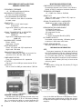
YOU SHOULD OWN
McIntosh
BECAUSE
• Mclntosh instruments are designed and manufactured for long life.
• Mclntosh instruments have always
been designed for long life with low
maintenance costs and high quality performance. Mclntosh instruments have been and are the
LABORATORY STANDARD
for the world.
TABLE OF CONTENTS
Power Amplifiers:
MC 2500, MC 2255, MC 2250, MC 2155, MC 2120,
MC 502
2-16
PreAmplifiers:
C 33, C 29, C 27, C 504
14-24
Tuners:
MR 80, MR 78, MR 75
25-37
Tuner-Preamplifier:
MX 117
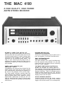
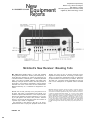
Receiver:
MAC4100 AM/FM Receiver
Preamplifier- Amplifier:
MA6200
38-45
46-50
51
Loudspeakers:
52-65
The Mclntosh Story
66-67
Equalizers:
MQ107, MQ 104
FM Guide.
68
.
.
• Until 1949 the performance requirements for a Mclntosh had
long been an engineering dream.
They became a reality with the introduction of the first Mclntosh
amplifier. Through all these years
Mclntosh has produced instruments that have exceptionally long
life. Clinics held ail over North
America have shown that most of
the Mclntosh instruments ever
manufactured still meet or exceed
their original exacting specifications.
• Used McIntosh instruments have
the highest resale value. Retailers
report that customers are constantly searching for used Mclntosh instruments. A Mclntosh does not remain on the "Used" display long.
You'll get more when you trade-in
your Mclntosh assuring you of
maximum return on your investment,
• Mclntosh dedication, not only to
improvements, but also to fundamentals, has justified many
patents on basic circuit structures
as well as refinements.
• Doesn't it make good sense to deal
with a company that wants to do as
much for you as it possibly can?
69-76
1
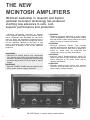
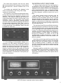
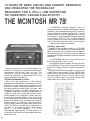
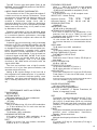
THE NEW
MCINTOSH AMPLIFIERS
Mclntosh leadership in research and bipolar
epitaxial transistor technology has produced
startling new advances in safe, cool,
superior performance and protection.
Mclntosh engineering continues to advance
power amplifier technology and protected performance. Experience and knowledge are the foundation on which the engineering superstructure is
built that supports the Mclntosh recognized reputation as Laboratory Standard for the world. A new
level of technology and a higher level of amplifier
performance is realized in the all new Mclntosh
Amplifiers.
LEADERSHIP
• Mclntosh life testing selects only components
that give the most trouble free performance. Added care in engineering, design and manufacturing
produces long product life at the peak of performance.
LEADERSHIP
• Mclntosh POWER GUARD assures maximum amplifier power without clipping distortion.
LEADERSHIP
• Mclntosh engineers developed a unique output
circuit configuration that is temperature stable
and that delivers clean output power at any level
without a trace of crossover distortion.
LEADERSHIP
• Mclntosh Automatic System . Test provides
positive protection and extends the long trouble
free life of an amplifier. Each time an amplifier is
turned on, seven tests are completed that
measure and verify accurate performance.
LEADERSHIP
• Mclntosh Output Autotransformers deliver full
power output and multiple feedback loops assure
lowest distortion at all power levels and all
speaker impedances.
LEADERSHIP
• Mclntosh designed mute circuits give positive
protection from transients due to turn on, turn off
power supply voltage changes.
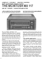
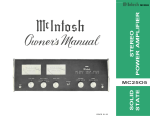
MC 2255 Shown in optional walnut veneer cabinet
2
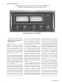
YOU ARE PROTECTED FROM
LISTENING TO AMPLIFIER
PRODUCED DISTORTION
WITH MCINTOSH
POWER GUARD
Plus:
• Mclntosh Output Autotransformer delivers full
power output. Multiple feedback loops assure
lowest distortion at all power levels and all
speaker impedances
• Mclntosh engineers developed a unique output
stage circuit arrangement that is completely
temperature accurate, that delivers clean output
power at any level without crossover distortion
• Mclntosh life testing of components permits component selection for trouble-free performance; added care in production engineering and manufacturing results in long product life
• Mclntosh designed "turn-on/mute" circuits provide positive protection from "turn-on transients"
and other potentially damaging noises
• Mclntosh POWER GUARD assures maximum
amplifier power without clipping distortion
40% harmonic distortion. The extra heat energy content of the clipped signal will damage most
speakers. Mclntosh leadership in engineering has
developed a new circuit that...(1) dynamically
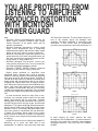
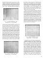
prevents power amplifiers from being overdriven inPIANO
30
0
-30
20
100
1K
10K
1K
10K
1K
10K
HERTZ
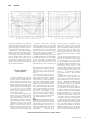
PIPE ORGAN
Higher power demands on amplifiers have
presented music listeners with a form of unpleasntness in listening, amplifier overload (hard clipping)
that looks and acts like square waves. Clipping is
caused when the amplifier is asked to produce more
power output with low distortion than it can deliver.
Clipping of a complex wave form is largely composed of odd order harmonics and intermodulation products. High order odd harmonics and intermodulation products are dissonant and are not musically
related to the signal being amplified. They are heard
as great and disappointing discordance and distortion.
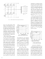
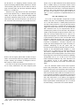
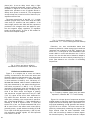
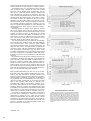
In most acoustical events we may listen to surprisingly low average power output but the peak
power requirements can be very high. Consider
these graphs of the power demanded of an amplifier
reproducing the piano, the pipe organ, and the bass
saxophone. The charts show that the peak power demand is almost 1000 times (30 dB) the average power
demand. Since it is necessary that these short interval power spikes be reproduced with low distortion,
it means the average power output of the power
amplifier must be limited to 1/1000th of its capability
or the listener must accept the discordant distortion
of clipping.
Amplifiers when driven to clipping are capable of
delivering up to twice the heat load to the
loudspeaker. In addition, they can have more than
30
0
-30
20
100
HERTZ
BASS SAXOPHONE
30
0
-30
20
100
HERTZ
to hard clipping. ..(2) which reduces the heat
developed in the loudspeakers. ..(3) assures that the
amplifier will produce its maximum output without
increased distortion. That circuit we call "POWER
GUARD."
3
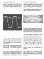
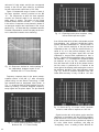
THE MCINTOSH POWER GUARD
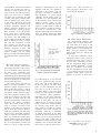
THE MCINTOSH POWER METERS
The Power Guard waveform comparison circuit
detects minute amounts of waveform difference between the output signal and the input signal. A
sampling of the program material at the output of
the amplifier is constantly compared with the program material at the amplifier input. Should the differences reach 1%, Power Guard goes to work.
Mclntosh developed output monitoring meters
add to your operating flexibility. Ordinary meters are
incapable of indicating the short interval information in a sound wave. The mass of the meter movement is too great to respond to the instantaneous
changes in music program material. That short interval information can have a duration as brief as onehalf of one thousandth of a second. Even should the
meter be capable of the high velocity movement the
human eye could not perceive the information.
Oscillogram of output waveform with and without Power Guard.
Input overdriven for each trace 20 dB.
Mclntosh engineering pursued both problems
electrically by developing new electronic circuits
that cause the meters to respond to short interval information with an accuracy of 98%! To permit the
eye to see such high speed motion the electronic circuits that drive the meter pointer are time stretched
so the meter pointer position can register in the persistence of vision characteristics of the human eye.
The meters indicate directly in watts, or can be
made to hold the highest reading and continuously
update on higher power or can be switched to be
peak reading — peak locking decibel meters.
In only a fraction of a millisecond Power Guard
dynamically reduces input level to prevent amplifier
overload yet permits the amplifier to deliver its absolute maximum power output without extra distortion. In addition, the output of the "waveform comparator" activates the front panel NORMAL and
LIMIT indicators.
The Power Guard circuit provides a precise visual
indication when the amplifier has reached full power
output. Any time that the input circuit is fed excessive amounts of signal causing waveform differences through the amplifier of 0.5%, the output
mode indicators change from green NORMAL to red
LIMIT automatically and instantaneously. This warning persists long enough for positive visual indication of clipping for a pulse that is so infrequent or
short that it would be impossible to be seen even on
an oscilloscope. The indicators will illuminate on
clipping for a pulse as short in time as 100 microseconds. You are always assured that the power of your
amplifier is as clean and distortion free as it can be.
4
When used as a watt indicating meter all the information is direct reading, without conversions or
complicated mathematics. In addition, as direct
reading meters they are calibrated in average watts
for a sine wave signal but respond to signal peaks.
The meters indicate direct power in watts. They
are calibrated in average watts for a sine wave
signal but respond to signal peaks. So, a 200
average watt indication also means 400 instantaneous peak watts. The meters are voltage actuated and indicate power accurately when the
amplifier is operated into rated output load impedances.
Watts Hold, permits the meter to lock to and indicate the highest power peak in a sequence of
peaks. The meter will be driven to maximum power
and electronically held there until a higher peak
passes through the amplifier. If no further peaks are
reached the meter needle will very slowly return to a
lower peak or to its rest position at a decay rate of 10
dB per minute.
The meters have extremely fast rise time, about
500 microseconds for 90% accuracy. A tone burst of
500 microseconds is almost inaudible even at full
power.
The meters are protected from damage in the
event of overloading in the wrong meter range.
AUTOMATIC TEST SYSTEM
The Automatic Test System provides positive protection and extends the long trouble free life of an
amplifier. Each time the amplifier is turned on an
Automatic Test System measures and verifies accurate performance at seven critical points in the
amplifier's circuits. The Automatic Test System
verification assures operational readiness before
operation starts and limits any damage should there
be component malfunction. Each time a test is
verified an LED number indicator shows which test
is being performed. An adjustable "beep" tone can
be heard with each test.
If in the testing an unacceptable voltage is encountered, the LED numeric designation locks to
isolate the faulty circuit. Faulty circuit identification
permits the service technician more efficient repair.
Without the Mclntosh Automatic Test System attempts to locate a fault by the probing and testing
needed, will often create additional problems by putting undue mechanical and electrical stress on the
circuit components. The Automatic Test System protects your investment.
THE MCINTOSH OUTPUT CIRCUIT DESIGN
To achieve long trouble free life in an amplifier it
is essential to have cool operation. Cool operation
results from the careful design of the output circuit,
matching of the output circuit to the loudspeakers
with an autotransformer and a mechanical design
that permits the use of generous sized heat sinks
providing adequate ventilation without the use of
fans.
The bipolar eptaxial output transistors and the
Mclntosh output circuit allows the amplifier to
operate as cool as possible. When there is limited
program demand on the amplifier only the optimum
number of output devices operate. When there is no
signal no output device is conducting. Conservative
Mclntosh engineering keeps operating temperatures
low assuring long life.
The interleaved multifilar wound Mclntosh designed autotransformer transfers all the power you paid
for to all impedance taps. You are not power penalized for operating at an output impedance of less than
8 ohms. The Mclntosh autotransformer does its outstanding job without adding phase shift, limiting frequency response or power output. The distortion
through the autoformer is 0.003% at 20 Hz and
unmeasurable at higher frequencies. In short, the
Mclntosh autotransformer is the ideal answer to a
difficult problem.
Heat sinks must be large and they must have adequate ventilation for effective cooling. For example
the MC 2255 has 1100 square inches (7.64 square
feet) of radiating surface. In addition, the chassis
has been designed to permit the maximum amount
of air to flow over the heat sinks to conduct away the
life limiting heat.
Mclntosh amplifiers provide the correct connection impedance to drive numbers of speakers simultaneously. For instance the 1 ohm output will drive
eight 8 ohm speakers and deliver full power without
overheating.
MC 2155 shown in optional walnut veneer cabinet.
5
test reports
"Reprinted with permission from the June 1982 issue of STEREO REVIEW magazine.
Copyright © 1982 Ziff-Davis Publishing Company. All rights reserved."
Mclntosh MC 2255 Power Amplifier
•
•
•
•
•
Mclntosh MC 2255 Power Amplifier
Power Rating: 250 watts per channel
Size: 16¼ x 14¾ x 7¼ inches
Weight: 82 pounds
Price: $2,750
HE Mclntosh MC 2255 basic power amplifier is rated to deliver its output into
loads of 1, 2, 4, or 8 ohms, from 20 to
20,000 Hz, with no more than 0.02 per cent
harmonic or intermodulation distortion. Its
stereo outputs may be paralleled or bridged
to drive a mono load with a maximum output of 500 watts at 0.02 per cent distortion.
Depending on the connection used, the
mono load impedance can be from 0.5 to 16
ohms.
The unusual load capabilities of the MC
2255 derive from the use of large autotransformers to match the output transistors to
their loads. Like vacuum-tube amplifiers,
the MC 2255 has output terminals designated for 1, 2, 4, or 8 ohms. Thus, regardless of the speaker impedance, the output
transistors are optimally loaded and can deliver their full power without excessive distortion or overheating.
The output stages of the MC 2255 operate in class-B, but a unique biasing system
completely eliminates the crossover distortion usually associated with class-B operation. This being the most efficient mode of
linear amplifier operation, the total power
consumption of the MC 2255 from the 120volt a.c. line is only 0.7 ampere at idle (or
normal playing volume) and 12 amperes at
full output. The input and driver stages
form a complete class-AB low-power amplifier which drives the front-panel headphone
T
6
jack as well as the power stages. Switches
connect the input sections for mono operation. In the MONO/PARALLEL mode the
right-channel input drives both output sections in phase, and for the MONO BRIDGE
mode the other input section is used as a
phase inverter so that the outputs can be
d r i v e n 180 degrees out of phase.
The power stages are protected by a novel
Power Guard circuit that makes it impossible to clip the amplifier output by overdriving it. A waveform comparator monitors the
input and output signals of the amplifier,
and if the output waveform differs from the
input by an amount corresponding to about
0.5 per cent harmonic distortion, a red LIMIT light glows on the panel (there are separate lights for the two channels). Any further increase in the drive level causes the
signal to be attenuated ahead of the output
section. This prevents the output from ever
exceeding its linear operating range (according to McIntosh, the amplifier can be
overdriven by 20 dB before distortion
reaches 2 per cent).
I n t e r n a l l y , the McIntosh MC 2255 is a
very complex amplifier, containing some
eighty-five transistors, forty-seven diodes,
and fourteen integrated circuits. Many of
its components are involved in the protective systems and in its novel self-test feature. Each time the amplifier is turned on,
an automatic seven-step test sequence
checks the key operating voltages for correctness. As each step is executed, the corresponding numeral lights up on a frontpanel display and a green light signals that
it has been passed. If any stage of the test is
not satisfactory, its number remains lit to
indicate the problem area. Two different
test speeds can be selected, and one can
choose to have a "beep" sound after each
step or to have the tests proceed in silence.
Two large meters are calibrated logarithmically from less than 2.5 milliwatts to 500
watts output (because of the output transformers, these readings are equally applicable to any of the load impedances for w h i c h
the amplifier is designed). Another scale
reads in decibels from -20 to + 2 (the latter corresponding to about 250 watts output). Knobs below the meters control LEFT
GAIN,
RIGHT/MONO GAIN,
METER RANGE
(-20 dB, -10 dB, 0 dB, WATTS, HOLD),
the SPEAKERS outputs, and POWER. The
HOLD position of the METER R A N G E switch
causes the meters to retain their highest
readings. The meter-driving circuits allow
them to respond to very short program
peaks, although they are calibrated in average watts.
At the right side of the panel are the two
indicator groups. The POWER G U A R D display
shows the number of the SYSTEM TEST sequence step as it is executed, and pairs of
red and green LEDs show either that the
L I M I T (of output power) has been exceeded
or that the amplifier operation is NORMAL.
Above this group, a meter group i l l u m i n a t e s
the words WATTS, HOLD, or DECIBELS, according to the setting of the METER RANGE
switch.
On the rear of the chassis are two sets of
barrier terminal strips for the speaker outputs, a single unswitched a.c. outlet, and the
holder for the 15-ampere line fuse. A threeposition MODE switch selects STEREO, MONO
BRIDGE, or MONO PARALLEL operation. Next
STEREO REVIEW
test
reports
to the two input phono jacks is a switch that
sets the i n p u t sensitivity to either 0.75 or 2.5
volts for f u l l output depending upon the associated e q u i p m e n t . (The l a t t e r is the normally preferred setting for most setups.)
The MC 2255 is a handsome and rugged
amplifier, following a long-standing McIntosh t r a d i t i o n in its styling and construction. The pane! and most of the top metalwork are finished in black, with front accents of silver and softly l i t blue-green meters. The chassis is chrome-plated. Also f u r nished w i t h the a m p l i f i e r are side brackets
and h a r d w a r e for the M c I n t o s h Panloc system for custom installations.
Mclntosh MC 2255
Power Amplifier
• Comment. M c l n t o s h (one of the oldest names in hi-fi, and perhaps the only
firm from its time to remain under the
original ownership) has earned an impressive reputation for t h e i r continued
support of their products, their except i o n a l l y conservative design and specifications, and generally outstanding quality The MC 2255, the f i r s t McIntosh
product we have reviewed in many
years, is a perfect example of the continuation of those policies.
In its circuitry and operating features,
the MC 2255 is quite u n l i k e any other
basic power a m p l i f i e r we have seen. By
using a u t o t r a n s f o r m e r s to match the
load impedance to the transistor requirements, McIntosh has made an a m p l i f i e r
capable of delivering its f u l l potential
performance into almost a n y load impedance it might encounter. That performance, as our tests have shown, is absolutely first-rate. It is d i f f i c u l t to imagine any home i n s t a l l a t i o n needing more
• Laboratory Measurements. Preconditioning the MC 2255 at o n e - t h i r d rated
power made the heat s i n k s very hot, but the
rest of the a m p l i f i e r remained comfortably
cool throughout our tests. In normal operation the MC 2255 is no more t h a n f a i n t l y
warm and has no need of a cooling fan or
any unusual ventilation precautions
With both channels driving 8-ohm loads
at 1,000 Hz the distortion was undetectable
( w e l l below the noise level) u n t i l we reached
10 watts o u t p u t , when it measured 0.00056
per cent. It increased very g r a d u a l l y w i t h
higher power to 0.0032 per cent at 250
watts and 0.0045 per cent at 300 watts. The
power than the MC 2255 delivers with
such apparent ease. Its noise, distortion,
s t a b i l i t y , and a n y other q u a l i t y one
m i g h t n a m e are quite l i t e r a l l y "state of
the art."
The Power Guard system is most effective in m a k i n g it impossible to hardclip the output of the amplifier. Regardless of how hard it is d r i v e n , it simply
cannot develop an audible amount of
distortion on musical program material
(2 per cent is well below the probable
threshold of a u d i b i l i t y of distortion in a
music system being driven to 350-plus
watts). This feature should also mean a
greatly reduced likelihood of b l o w i n g
out a speaker, since clipping is a common cause of tweeter damage. For the
nontechnical user, the self-test feature is
mostly a "security blanket," although
we can appreciate that it would also simplify troubleshooting and servicing.
c
LEARLY, no effort has been spared in
the design and construction of this amplifier. This sort of perfectionism carries
a considerable price, both in dollars and
pounds (avoirdupois, not sterling!). Considering the probable long l i f e of the MC
2255, t h a t price does not seem at a l l
unreasonable
-Julian D. Hirscti
m a x i m u m power (corresponding to "clipping power," except t h a t the waveform
could not be made to clip) was about 357
watts, w i t h distortion reading 0.24 per cent
at the l i m i t i n g point. The output into 4
ohms (using the appropriate output terminals) was also 357 watts, and we were able
to develop 420 watts per channel into 2-ohm
loads.
At the rated 250 watts output into 8
ohms, the m a x i m u m distortion was 0.01 per
cent at 20 Hz. Over most of the audio range
it was about 0.004 per cent, rising to 0.009
per cent at 20,000 Hz. At lower power outputs the distortion was s u b s t a n t i a l l y lower.
The amplifier sensitivity (using the 2.5-volt
switch setting) was 0.15 volt for a 1-watt
reference output, and the A-weighted noise
and hum level was 86 dB below 1 watt. The
frequency response of the a m p l i f i e r was
w i t h i n +0. - 0 1 dB from 20 to 20,000 Hz
and was down 0.9 dB at 5 Hz and 3 dB at
150 k H z .
The amplifier rise time was about 3 microseconds, and its I H F slew factor was
about 10 The I H F i n t e r m o d u l a t i o n distortion, measured with 18- and 1 9 - k H z signals, was — 94 dB for the second-order component at 1,000 Hz and -67 dB for each of
the third-order products at 17 and 20 kHz,
a l l being referred to a 250-watt level.
The clipping headroom of the a m p l i f i e r
was 1.55 dB for 4- and 8-ohrn loads and
2.55 dB for 2-ohm loads. The dynamic power o u t p u t was 455 to 466 watts, depending
on the load impedance, giving dynamicheadroom ratings of 2.65, 2.7, and 2.5 dB
for loads of 8, 4, and 2 ohms, respectively.
The meters read quite accurately (about
0.2 dB high at f u l l power) and responded to
very brief transient signals. They are driven
from the class-AB input amplifier instead
of from the output stages as in most a m p l i fiers, so the meter readings are unaffected
by switching off the speakers. We found the
headphone volume to be only marginally
useful with 600-ohm phones. It was adequate w i t h conventional-impedance phones.
Reprinted through the kind permission of Stereo Review
STEREO R E V I E W
7
Output Transformers
in Transistor
Power Amplifiers
by Sidney Corderman*
Output transformers can make transistor power amplifiers more reliable,
more flexible, and more powerful. At
the same time output transformers
offer the best continuous protection
to loudspeakers against the hazards of
avalanche failure of output transistor
devices.
Time has shown that o u t p u t transformers make transistor amplifiers
operate cool and safe. The output
transformerless
amplifier
(OTL)
becomes less exciting when amplifiers
must give long, consistent and predictable operation.
Let's take a look at transformers in
general
at their past and present
use in amplifiers - - - and at why
Mclntosh Laboratory continues to be
the leader in the amplifier field with
the use of transformers.
push pull, we had a tube load impedance of 4000 ohms trying to deliver
Remember Vacuum Tube Amplifiers?
Until the early 1960's, McIntosh
and just about everyone else in the
high fidelity component manufacturing business produced vacuum tube
power amplifiers exclusively. The
familiar push-pull circuit of Fig. 1
reigned supreme. In that circuit we
had a pair of tetrode or pentrode tubes
with their high output impedance trying to deliver power to low impedance
loudspeaker systems. A transformer
was needed to provide the necessary
impedance match between them. But
there were problems in t r y i n g to
achieve an optimum transfer of power
between tubes and speakers. Typically,
using a pair of 6L6 output tubes in
power to, say, an 8 ohm speaker load.
The impedance ratio was 500 to 1,
and the necessary transformer had to
have a turns ratio of around 23 to 1
(turns ratio varies as the square root of
the impedance ratio). The required
turns ratio created problems at both
ends of the audio frequency spectrum.
Leakage inductance and shunt capacitance (represented as dashed lines in
Fig. 1) caused high frequency roll-off.
The primary inductance of the transformer together with its inherent nonlinear characteristics placed limits on
low-frequency response. And the
energy stored in the unwanted leakage
inductance caused notch distortion, as
illustrated in Fig. 2.
*
8
Fig. 2 - Notch distortion in a typical Class B
output circuit
Fig. 1 — Typical push — p u l l o u t p u t circuit
(see story tor dashed line information)
Vice President of Research and Development, McIntosh Laboratory Inc.
The McIntosh Unity Coupled Circuit
Long before the advent of transistorized power amplifiers, McIntosh
found an effective way to solve these
problems. We called it the Unity Coupled Circuit. The basic configuration
is illustrated in the diagram of Fig. 3.
Fig. 3 — McIntosh "notch free" low
distortion Unity Coupled Circuit
The impedance ratio required between
primary and secondary has been reduced by a factor of four-to-one compared with the conventional arrangement. It is now 125 to 1 (1000/8).
The turns ratio is therefore only half
of w h a t it was before. Leakage inductance is therefore much lower, and so
is the shunt capacitance across the
windings. The use of a bifilar winding
technique completely eliminates the
leakage inductance problem of coupling between the sections of the primary windings. It was the developm e n t of the U n i t y Coupled Circuit
by McIntosh (the circuit is patented)
way back in 1947 that enabled us to
produce amplifiers which were a whole
order of magnitude lower in distortion than the competition of those
days. Typically, we were able to produce power output circuits with total
harmonic distortion of under 1.0%
even before the distortion-reducing
negative feedback loop was added.
With just 20 dB of feedback applied,
the THD was further reduced to under
0.1%!
What About Transistor Amplifiers
The audio industry welcomed the
power output transistor as the solution
to all its problems. After a few faltering starts (early germanium power
output transistors were notoriously
unreliable and easily destroyed by high
operating temperatures), silicon power
transistors became the standard power
device in power amplifiers.
Since power output transistors exhibit a low output impedance, it was
possible to design output circuits to
match 8-ohm loads directly—without
the need for a matching audio output
transformer. Indeed, most OTL amplifiers, when coupled to 8-ohm resistive
loads for test purposes, can deliver full
rated power to those loads for long
periods of time without overheating or
exceeding safe thermal dissipation
limits. The trouble is that we don't
listen to resistors we listen to loudspeakers. It will come as no surprise to
you to learn t h a t speakers having a
"nominal" impedance of 8 ohms often
measure lower and higher impedance
values at different audio frequencies.
Then, too, consider the fact that many
popular speaker systems have nominal
impedances of 4 ohms, and the impedance of 4 ohm speakers can easily dip
down to as low as 2 ohms at certain
frequencies. What happens to an OTL
amplifier with such low impedances
connected to it? In theory, if an output stage is designed to match an 8
ohm impedance, its power " o u t p u t
capability should double when it's
connected to a 4 ohm impedance. But
as this mismatch occurs, thermal dissipation increases rapidly. In fact,
operating into a 4 ohm load, heat dissipation is double what it would be
when operating at 8 ohms, as illustrated in Fig. 4. Unfortunately, if the
amplifier was designed for 8-ohm operation, its thermal dissipation limits
were designed with some safety factor
Heat dissipation
capacity required to
meet FTC rating
at 8 ohms.
Load impedance in ohms (1000%=Heat
produced at rated output into 8 ohms.)
Fig. 4 - Heat produced by transformerless
amplifier at various load impedance
for 8 ohm operation, so as to meet the
new FTC preconditioning requirements. These call for the amplifier to
be able to deliver one-third rated
power at rated impedance for one
hour. But, as you can see from Fig. 4,
the safety margin is not nearly great
enough to permit operation at 4-ohms
—or 2-ohms-or 1-ohm impedances.
Remember, too, that many amplifiers
and receivers have provisions for connection of more than one pair of
speakers for use in different listening
rooms, so that even if 8-ohm speakers
are selected, using double pairs of
them results in a 4-ohm net nominal
impedance even before allowing for
downward variations in impedance
at specific frequencies in the audio
spectrum. So, unless manufacturers are
willing to resort to disproportionately
massive heat sinks, cooling fans or
combinations of both, designing power
amplifiers that can deliver their maximum powers at both 8 ohms and im-
pedances of 4 ohms and lower becomes physically impractical in the
case of the OTL amplifiers.
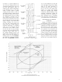
Fig. 6 - Performance of MC 2300
The Answer-Output Transformers!
If a transistorized amplifier were
equipped with an output transformer,
you could move up or down in load
impedance and maintain full power
ratings without over-dissipating anything, since the amplifier's output
stages would always be working into
an ideal load.
To many hi-fi enthusiasts, output
transformers tend to create visions of
compromised design. That is just not
the case today. Technology in materials and transformer design methods
have advanced significantly in recent
years and, remember, we're dealing
with low impedance devices-not tubes.
It's no longer necessary to translate
impedances from a "plate circuit" to a
speaker-a step down of several hun-
(* - - - Continuous operation not possible
due to overheating. Protection circuit is assumed to current limit when load falls below 4 ohms, in actuality the o u t p u t into 4
ohms and lower impedances will fall below
the values shown.)
Fig. 7 - Performance of non McIntosh
transformerless amplifier rated for
300 watts in 8 ohm load
9
Fig. 5 - McIntosh MC 2205 o u t p u t stage and transformer
dred to one. With transistor output
stages, a ratio of only about 4 to 1 is
required. In tube amplifiers, extremely
good balance in the push-pull primary
was required if notch distortion was to
be avoided. Now, using a single ended
push-pull transistor output stage the
transformer can be driven in a single
ended fashion. One end of the winding
Is returned to ground potential. With
the transformer at ground, no isolation
is required between the input and output and therefore a simple autotransformer can be used.
Fig. 5 shows a typical arrangement used in our new MC 2205 amplifier. The output stages are designed to
work o p t i m a l l y i n t o a load impedance
of 2.1 ohms and it becomes a simple
matter to "tap into" the auto-transformer for that precise impedance
match. Taps for 1 ohm, 2 ohm, 4 ohm
and 8 ohm operation are arranged so
that the output transistors continue to
work into their optimum impedance.
The result: full power output at any of
these impedances, with no possibility
of thermal over-dissipation.
Our popular MC 2300 amplifier
also uses an auto-transformer and
Fig. 6 shows how that amplifier is able
to deliver its full rated power (300
watts RMS per channel) into any
impedance from 0.5 ohms to 16 ohms,
as well as to 25 volt and 70 volt multispeaker system taps on the transformer. If we compare these results with
those obtained with a similarly rated
10
transformers in a moment) can introduce about 3 degrees of phase shift at
20 kHz (Fig. 8A), which is certainly
insignificant. The typical volume control used on amplifiers (both those
that are OTL and those equipped with
transformers) introduce more s h i f t
t h a n that— about 20 degrees in fact
(Fig. 8B). Since an output transformer
is driven from an extremely low impedance, there is actually more lowfrequency phase shift caused by the
usual input coupling capacitor at these
low frequencies than by the transformer.
So, why haven't more manufacturers used output transformers on solidstate amplifiers? Possibly they are not
aware of the technology, but more
likely they don't want to spend the
extra cost. A good transformer is an
expensive component. It is heavy,
takes up a fair amount of space and
contradicts the audiophile's notion
that transistorized equipment must be
small and lightweight. Be that as it
may, the FTC regulations suggest that
o u t p u t transformers are the only logical solution to rating audio amplifiers
honestly at 4, 8, 16 or any other
impedance required.
Fig. 8A - Typical of phase shift in
McIntosh auto-transformer at 8 ohms
OTL amplifier (Fig. 7) we see that at
all but 8 and 16 ohms, continuous
operation at theoretical maximum
power is impossible because of overheating and protection circuit limiting. Operation at 16 ohms, though
possible, is limited to a maximum
power output of 150 watts, in this
case, while operation into a 70-volt
line is impossible because of limitations in power supply voltages.
What About Phase Shift?
Critics opposed to the use of transformers in output circuits of audio
amplifiers arc quick to point out that
"transformers introduce phase shift"
at the low and high frequency extremes. As a matter of fact, a properly
designed transformer (and we'll get
into some of the factors that are involved in designing McIntosh output
1 watt, 8 ohms
— Volume Control Clockwise
— Volume Control 12 o'clock
Fig. 8B - Typical phase shift
in a complete Mclntosh amplifier
Not Just Any Transformer!
At M c l n t o s h , we wind all our own
output auto-transformers. Of course,
we could purchase them from any one
of a number of transformer companies
who do nothing but wind transformers
(our power transformers are, in fact,
purchased from other suppliers), but
we have long since found that transformers can't always be made successfully "according to the book". A great
deal of experimentation is required before a new design of a transformer can
be mated to a specific amplifier circuit. We went through dozens of developmental samples in the case of our
new MC 2205 amplifier. What we
ended up with it shown schematically
in the diagram of Fig. 9. The transformer is trifilar wound to provide
coupling between sections. It takes 23
individual windings to make this output transformer. There are five different winding sections, all five of which
are connected in parallel. We use
grain oriented silicon steel core laminations because that kind of core means
less iron-and less iron in turn means
tighter coupling. It also means lower
winding resistance for a given size
wire. The grain oriented silicon steel
means that it has a higher magnetic
saturation point-about 17 kilogauss
versus 12 to 13 kilogausses for the
non-oriented variety. There is therefore less core loss, or, to put it simply,
we end up with a more efficient transformer-one which couples more of
the available amplifier power to the
speaker loads. To further improve coupling, we don't use any interlayer insulating paper in a power transformer
that might pose a breakdown problem.
But since our polyurethane insulated
wire is rated at 4000 volts per mil (and
since the highest voltage we're talking
about for an audio transformer is
about 56 volts), this really is no problem at all. All of our output transformers arc potted with material
which has especially high thermal
conductivity. Besides helping to keep
operating temperatures within the
transformer down, this compound reduces lamination buzz to inaudible
levels. We figure you'd rather listen to
your speakers than to our transformers!
Our Transformers Are Only Part
of The Story
Fig. 9 - MC 2205 output
auto-transformer schematic diagram
Whether an amplifier uses an output transformer or not, its output devices must be designed to work into an
optimum load so that maximum current delivered by the output transistors never exceeds the safe operating
area specified for the transistor. Fig.
11 shows current versus voltage limitations for the epibase type of output
transistor used in our MC 2205 amplifier. If all amplifier loads were purely
resistive, staying within the safe operating area would be relatively simple,
but the fact is that speakers often pre-
Output volts
Fig. 10-Load and limiting data of
the McIntosh MC 2205 measured at 8 ohm output
11
provided for reactive loads.
Collector volts
Fig. 11 - Current versus voltage
limitation epibase type
output transistor
fiers. In Fig. 10 we have combined the
safe operating diagram of Fig. 10 with
load and limiting characteristics at the
8-ohm tap of our MC 2205. As you
can see, even when the load is totally
reactive, every possible voltage and
current condition falls within the
safe operating area of the o u t p u t devices used. Compare this diagram with
Fig. 12 derived from d a t a concerning
the output transistors used in a currently available high-powered amplifier.
Note that inadequate protection is
To Sum It All Up
The points we've tried to make are
relatively few, but they spell the difference between a McIntosh outputtransformer equipped amplifier and
every other kind of amplifier around.
1. A transformer equipped amplifier will deliver rated power at any impedance for which a transformer tap
is provided.
2. An OTL amplifier designed for
8-ohm operation cannot operate safely
(according to the FTC rules) when
driving lower impedances (4 ohms,
2 ohms, etc.), yet such loads commonly occur either because of speaker impedance variations with frequency or
because of paralleling of multiple
speaker systems across one channel
of an amplifier.
3. The new FTC power rule regarding audio amplifiers has forced many
manufacturers to omit 4-ohm ratings even though 4-ohm speakers arc in
common use. McIntosh transformerequipped audio amplifiers deliver f u l l
power at any impedance for which a
transformer output tap is provided.
4. Because of their design, McIntosh
transformers introduce less series leakage inductance than is commonly encountered with OTL amplifiers which
require a series inductance between
the output circuit and the speaker connection for amplifier stability. At the
8 ohm tap of our MC 2205, leakage inductance is a low 3.5 microhenries.
This represents an impedance of only
2.2 ohms at a frequency of 100 kHz.
5. Properly designed output transformers impose no limitations on frequency response. At the 8-ohm tap of
the MC 2205, response is down 0.3 dB
at 50 kHz. W i t h a 4-ohm toad connected, response is down 0.1 dB at
50 kHz.
6. Phase response of the MC 2205
amplifier, using its specially designed
output transformer, is accurate to
within 9 degrees at the 8 ohm tap at
a frequency of 50 kHz and undergoes
zero degrees of phase shift at 20 Hz.
At t h e 4-ohm tap, phase shift at 50 kHz
is only 7.2 degrees.
Next time anyone gets into an argument with you concerning the attributes of an OTL amplifier versus a
McIntosh transformer-equipped amplifier, you might let your adversary read
t h i s story.
Output volts
Fig. 12 — Load and limiting data of
a non McIntosh high-powered transformerless amplifier measured at 8 ohms o u t p u t .
12
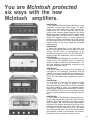
You are Mclntosh protected
six ways with the new
Mclntosh amplifiers.
PROTECTION
1. The patented Mclntosh Sentry Monitoring circuit
constantly monitors the output signal. At signal
levels up to rated output this circuit has high impedance and has no effect upon the output. If the
power output exceeds design maximum, the Sentry
Monitoring circuit operates to limit the signal to the
output transistors. In the event of a short circuit
across the amplifier output or severe impedance
mismatch the Sentry Monitoring circuit will protect
the output transistors from failure. Both positive and
negative halves of the output signal are monitored
independently.
PROTECTION
2. Should the temperature of the heat sinks rise
above normal through restricted ventilation or other
causes, the AC Power is disconnected by an
automatic heat sensing relay. The AC power will be
restored when the temperature returns to normal.
PROTECTION
3. Any loudspeaker damaging DC component in the
output circuit, from whatever cause, is shunted to
ground through the Mclntosh autotransformer. You
and your speakers are protected completely from
this kind of amplifier failure.
PROTECTION
4. Mclntosh gives you a money back guarantee of
performance. Your Mclntosh instrument must be
capable of meeting its published performance limits
or you get your money back. No other manufacturer
offers you this money back guarantee of performance.
PROTECTION
5. The Mclntosh 3 Year Service Contract protects
you from the cost of repair for three full years
because Mclntosh will provide the service materials
and labor needed to return the measured performance to the original performance limits. The SERVICE CONTRACT does not cover any shipping costs
to and from the authorized service agency or the factory.
PROTECTION
6. The Automatic Test System provides positive protection and extends the long trouble free life of an
amplifier. Each time the amplifier is turned on seven
tests measure and verify accurate performance.
Automatic Test System protects by verifying circuit
readiness before operation starts. Each time a test
is verified a numeric indicator turns on to indicate
the test being performed. If in the test countdown an
unacceptable voltage is encountered, the numeric
designation locks to isolate the faulty circuit.
13
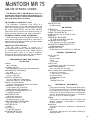
POWER AMPLI
MC 2500
POWER OUTPUT STEREO
Minimum Watts,
Both Channels Operating
500 Watts Per
Channel
POWER OUTPUT MONO
Minimum Watts
1000 Watts
POWER BAND WIDTH
20 Hz to 20 kHz
TOTAL HARMONIC DISTORTION
Maximum, 250 mW to Rated
Power, 20 Hz to 20 kHz
0.02%
OUTPUT LOAD IMPEDANCE
Stereo
Mono
1/2, 1, 2, 4, 8, 16 W
INTERMODULATION DISTORTION
Maximum, 250 mW to Rated Power
0.02%
FREQUENCY RESPONSE
20 Hz to 20 kHz
(at 1 Watt)
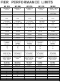
Performance limits are the maximum
deviation from perfection permitted for a
Mclntosh instrument. We promise you that
when you purchase a new Mclntosh product from a Franchised Mclntosh dealer it
will be capable of performance at or exceeding these limits or you can return the
unit and get your money back. Mclntosh is
the only manufacturer that makes this
statement.
-95 dB
OUTPUT VOLTAGES FOR
DISTRIBUTION SYSTEMS
25 Volts
DAMPING FACTOR
greater than 30
14
50.000 W
INPUT SENSITIVITY
0.75 or 2.5 Volts
POWER REQUIREMENT
AC Line Voltage - Frequency
Watts at No Signal
Watts at Rated Output
120V, 50-60 Hz
75 Watts
1800 Watts
SEMICONDUCTOR COMPLEMENT
Transistors
Diodes
Integrated Circuits
SIZE
Panel Height
Panel Width
Depth
FINISH
Mclntosh audio power ratings are stated
in accordance with the Federal Trade
Commission Regulation of November 4,
1974 concerning power output claims for
amplifiers used in home entertainment
products.
+ 0. -0.25 dB
NOISE AND HUM
Below Rated Output
INPUT IMPEDANCE
PERFORMANCE GUARANTEED
1, 2, 4, 8 W
91
35
6
10-1/2" (26.7cm)
19" (48.3cm)
17" (43.2cm)
Gold and Black
Panel, Black
Knobs
WEIGHT
Net
In Carton
129#(58.5kg}
144#(65.3kg)
HEAT SINK AREA
1990 sq. in.
SPECIAL FEATURES
Power Guard
Output Autoformers
Automatic Test System
Output Meters: Calibrated in Watts
Output Meters: Calibrated in dB
Thermal Turn-Off
Sentry Monitor
D.C. Speaker Protection
Output Limit Indicator
Panloc Mounting
Cooling: Convection
X
N/A
X
X
X
X
X
X
N/A
N/A
FIER PERFORMANCE LIMITS
MC 2255
MC 2250
MC 2155
MC 2120
MC 502
250 Watts Per
Channel
250 Watts Per
Channel
150 Watts Per
Channel
120 Watts Per
Channel
75 W/Chan. 2.7 to 4 W
50W/Chan. 8 W
500 Watts
500 Watts
300 Watts
240 Watts
150 Watts
into 8 Ohms
20 Hz to 20 kHz
20 Hz to 20 kHz
20 Hz to 20 kHz
20 Hz to 20 kHz
20 Hz to 20 kHz
0.02%
0.02%
0.02%
0.1%
0.02%
1, 2, 4, 8 W
1/2, 1, 2, 4, 8, 16 W
1, 2, 4, 8 W
1/2, 1, 2, 4, 8, 16 W
1, 2, 4, 8 W
1/2, 1, 2, 4, 8, 16 W
2, 4, 8, 16 W
1, 2, 4, 8 W
2.7 to 8 W
8W
0.02%
0.02%
0.02%
0.1%
0.02%
+ 0, -0.25 dB
+ 0, -0.25 dB
+ 0, -0.25 dB
+ 0, -0.25 dB
+ 0, -0.25 dB
-95 dB
-95 dB
-95 dB
-95 dB
-95 dB
25 Volts
25 Volts
25 Volts
25 Volts
25 Volts (Stereo Only)
greater than 30
greater than 30
greater than 30
14 to 50
>50
50,000 W
50,000 W
50,000 Si
100,000 W
75,000 W
0.75 or 2.5 Volts
0.75 or 2.5 Volts
0.75 or 2.5 Volts
0.75 or 2.5 Volts
0.75 or 2.5 Volts
120V, 50-60 Hz
70 Watts
1440 Watts
120V, 50-60 Hz
84 Watts
1440 Watts
120V, 50-60 Hz
84 Watts
720 Watts
120V, 50-60 Hz
50 Watts
460 Watts
120, 50-60 Hz
20 Watts
400 Watts
76
37
9
81
47
14
39
24
2
39
20
85
47
14
4
7-1/8" (18.1cm)
16-3/16" (41.1cm)
14-1/2" (36.8cm)
6-31/32" (17.7cm)
16" (40.6cm)
14-1/2" (36.8cm)
5-7/16" (13.8cm)
16" (40.6cm)
14-1/2" (36.8cm)
5-7/32" (13.3cm)
16" (40.6cm)
14-1/2" (36.8cm)
3-5/8" (9.2cm)
16" (40.6cm)
14-1/2" (36.8cm)
Black Glass Panel,
Gold/Teal Nomenclature, Gold and
Black Knobs
Gold Panel
Gold and Black
Knobs
Black Glass Panel,
Gold/Teal Nomenclature, Gold and
Black Knobs
Gold Panel,
Gold and Black
Knobs
Black Glass Panel,
Gold/Teal Nomenclature, Gold and
Black Knobs
82# (37.2kg)
96# (43.5kg)
80# (36.3kg)
94# (42.6kg)
65# (29.5kg)
77# (35kg)
57# (26kg)
70# (32kg)
27# (12kg)
38#(17kg)
1080 sq. in.
1080 sq. in.
772 sq. in.
772 sq. in.
513 sq. in.
X
X
X
X
X
X
X
X
X
X
X
X
X
X
N/A
N/A
X
X
X
X
N/A
X
X
X
X
X
X
X
X
X
X
X
X
X
X
N/A
N/A
N/A
X
X
X
X
N/A
X
X
N/A
N/A
N/A
N/A
X
X
X
X
X
X
" 5
THE McINTOSH C 27
STEREO PREAMPLIFIER
STATE-OF-THE-ART
PERFORMANCE WITH
FLEXIBILITY
PERFORMANCE LIMITS and RATINGS
FREQUENCY RESPONSE:
+ 0, -0.5 dB 20 Hz to 20,000 Hz.
DISTORTION:
Will not exceed 0.05% at rated output level, 20 Hz
to 20,000 Hz.
INPUT SENSITIVITY AND IMPEDANCE:
Auxiliary 1 and 2, Tuner, Tape 1 and 2: 250
millivolts at 100,000 ohms. Phono 1 and 2: 2
millivolts at 47,000 ohms and 100 pF.
HUM AND NOISE:
Auxiliary 1 and 2, Tuner, Tape 1 and 2: IHFA 90 dB;
unweighted 85 dB below rated output. Phono 1
and 2 IHFA 85 dB; unweighted 80 dB below 10
millivolts input.
OUTPUT LEVEL:
Main Output: 2.5 volts with rated input. Maximum
output is greater than 10 volts. Tape Output: 0.25
volts with rated input. Maximum output is greater
than 10 volts. Center Channel Output: (L + R) 2.5
volts with rated input.
SEMICONDUCTOR COMPLEMENT:
18 silicon-planar transistors, 4 silicon diodes, 5
light emitting diodes.
AC POWER OUTLETS:
1 unswitched (red), 4 switched (black).
POWER REQUIREMENT:
120 volts, 50/60 Hz, 15 watts.
FACILITIES AND FEATURES
BASS:
Separate 11 position rotary switches for each
channel. - 17 dB to + 16 dB at 20 Hz.
TREBLE:
Separate 11 position rotary switches for each
channel -20 dB to +20 dB at 20kHz.
LOUDNESS:
Flat response, or continuously variable loudness
equalization as volume level is reduced.
BALANCE:
Natural balance at center position, attenuation of
left or right channel by rotating control.
VOLUME:
Precision step attenuator for precision tracking at
all listening levels. Does not change stereo
balance as volume is changed.
INPUT:
5 positions—Auxiliary 1 and 2, Tuner, Phono 1 and 2.
MODE:
7 positions—Left channel only to both speakers.
Right channel only to both speakers, Stereo
Reverse, Stereo, Mono (L + R), L + R to Left
speaker only, and L + R to Right speaker only.
16
TAPE MONITOR:
Two pushbutton switches. Either of two tape
recorders may be monitored.
TAPE COPY SWITCH:
Two pushbutton switches. Either of two tape
recorders may be connected to copy from one to
the other in either direction.
LF FILTER (Rumble Filter):
Flat or roll-off 6 dB per octave below 50 Hz, down
12 dB at 20 Hz.
HF FILTER (Scratch Filter):
Flat or roll-off 6 dB per octave above 5kHz, down
12 dB at 20k Hz.
C 504 is a compact
state-of-the-art preamplifier.
PERFORMANCE LIMITS and RATINGS
C 504 is the same as the preamplifier section of
the MX 117 found on page 38.
MECHANICAL INFORMATION
SIZE:
Front panel measures 16 inches wide (40.6 cm) by
3 5/8 inches high (9.2 cm). Chassis measures 14
3/4 inches wide (37.5 cm) by 2 3/8 inches high (6.0
cm) by 14 1/2 inches deep (36.8 cm), including connectors. Knob clearance required is 1 1/4 inches
(3.2 cm) in front of mounting panel.
FINISH:
Front panel is anodized gold and black with
special gold/teal nomenclature illumination.
Chassis is black.
MOUNTING:
Mclntosh developed professional PANLOC.
WEIGHT:
14 pounds (6.4 kg) net, 25 pounds (11. kg) in shipping carton.
Electronic Laboratories'
PRODUCT
ANALYSIS
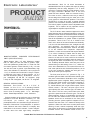
THE McINTOSH C 27
STEREO PREAMPLIFIER
Fig.1 - Front view
MANUFACTURER'S PUBLISHED
LIMITS (SPECIFICATIONS):
PERFORMANCE
Rated Outputs: Main, 2.5 volts (Maximum greater
than 10 volts) into 22k ohm load or greater; Tape,
0.25 volts (Maximum greater than 1 0 voltsl into 22k
ohm load or greater; Center Channel (L+ R ) , 2.5 volts
into 22k ohm load or greater. Input Sensitivities: High
Level, 250 millivolts at 1 00k ohms; Low Level (Phono
1 & 2 ) , 2 millivolts at 47k ohms and 1 00 pF. Frequency Response: (any input): 20 Hz to 20 kHz, +0, -0.5
dB. Hum and Noise: (Phono): 80 dB below 1 0 mV input, unweighted, 85 dB IHF "A" weighted; (High
Level): 85 dB unweighted; 90 dB IHF "A" weighted.
GENERAL SPECIFICATIONS:
Dimensions: Front Panel: 16" W x 5 - 7 / 1 6 " H.
Chassis: 1 5" W x 5" H x 1 3" D including PANLOC
shelf and back panel connectors. Required knob clearance in front of mounting panel: 1 1/2". Net Weight:
20 Ibs. Power Requirements: 1 20 V, 50/60 Hz.
Serious devotees of the audio art may be somewhat
surprised to find that Mclntosh Laboratory Inc. has
introduced
yet
another
top
performing
preamplifier/control unit, less than one year after the introduction of their all-out C 32 preamplifier. In previous
times, Mclntosh was never noted as a company that
subscribed to the annual cosmetic "model changes"
so often seen from other high fidelity component
manufacturers. Well, for all those thousands of
dedicated Mac fans let us preface this report by stating
emphatically that the newly designed C 27 is much
more than a cosmetic face-lift of older models. In fact,
the highly acclaimed "Mclntosh look" of the front
panel has been retained, while new internal circuitry,
from stem to stern, makes this new entry a state-ofthe-art design that should enjoy the same sort of longevity typical of other Mclntosh products. The earlierintroduced C 32 was, as we said, a multiple featured
product, with such built-in accessory features as a full
five-control graphic equalizer and an adjustable linear
expander, not to mention its fully separate monitoring/headphone amplifier output facilities.
The C 27 takes a more restrained approach in which
those features that are deemed important to most preamplifier/control users are retained but other accessory
facilities are omitted in favor of a suggested retail price
that will be affordable to a greater number of potential
purchasers. Think of the C 27 as a "middle of the
road" unit in terms of its control facilities and flexibility.
It is not a unit that subscribes to the "straight wire with
gain" approach - an approach which we, at least,
have always felt is a bit unrealistic. After all, how many
of us are blessed with companion components,
speakers, or even room acoustics that require absolutely no control "tweaking"? Rather than do away with
such control features as tone controls or filters, it
seems to us that it is far more useful for the consumer
to have these facilities providing that their presence in
the signal path does not introduce any form of distortion. Evidently Mclntosh felt the same way and, as we
learned during our lab testing of the C 27, these features, when deactivated or, in the case of the tone controls, when placed in their nominal flat positions, do not
in any way negate the "straight wire with gain" concept which some purists espouse.
The front panel of the C 27, pictured in Fig. 1, is
anodized gold and black with Mclntosh's familiar goldteal panel nomenclature illumination which magically
appears when power is applied. Rotary controls along
the top of the panel include a five-position program input selector (aux 1, aux 2, tuner, phono 1 and phono
2 ) , a mode selector (left or right to both outputs, stereo
reverse, stereo, L + R mono, left plus right to left or
right outputs) and, at the extreme right, the master volume control. The four rotary control sets at the lower
right of the panel are dual concentric types. The first of
these introduces, singly or in combination, the high and
low cut filters and selects either or both sets of loudspeakers which can be switched via the front panel
providing that the power amplifier's outputs are connected to the rear of the C 27 instead of directly to the
speakers. Bass and treble tone controls permit tonal
tailoring of each channel separately while the rightmost control in this group is a combination balance and
loudness control. The loudness control of the C 27
Printed With The Permission Of Electronics Laboratories
17
works a bit differently from that contained in the C 32.
The user is instructed to set the volume control for
maximum ( l i f e l i k e ) listening levels while the loudness
knob is set to its "flat" (counterclockwise) position.
Then, for lower listening levels, the loudness control is
rotated (rather than the volume control) and proper
Fletcher-Munson compensation is introduced as listening levels are lowered.
Completing the panel layout is a group of pushbuttons and a headphone jack at the lower left. The
buttons, five in a l l , take care of the two tape monitor
circuits and provide tape dubbing from either of two
connected tape decks to the other.
The final button turns on power to the unit and has
an illuminated rectangle just above it to indicate that
power is on.
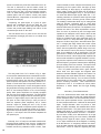
Fig. 2 - View of back panel
The rear panel of the C 27 is shown in Fig. 2. Adjacent to the four switched and one unswitched convenience AC receptacles are three sets of spring-loaded
terminals which require only that the stripped ends of
power amplifier and speaker connecting cables be inserted in small holes that are exposed when the terminal keys are depressed. It is this arrangement which
brings speaker switching capability to the front panel of
the C 27, and a handy feature it is, too, since most high
quality basic power amplifiers are normally equipped
with only one set of speaker terminals. The right portion
of the rear panel is equipped with the necessary phonotip jacks for signal inputs, tape in and tape out circuits,
two pairs of main output jacks (in case you want to
feed two separate power amplifiers) and a "center
channel" output for feeding the sum ( L + R ) of both
channels to a separate monophonic power amplifier for
background music in an alternate location or for powering a center-channel speaker system in the main listening area. A 0.5 ampere line fuse holder completes the
rear panel layout.
Circuit Highlights
Internally, the C 27 major circuit board contains all of
the audio signal handling active circuitry, including the
preamplifier-equalizer low level stages. Smaller p.c.
modules include the pushbutton switch circuits, input
18
terminal boards, a switch indicator circuit board (for illuminating the front panel LED's that light up when
tape monitoring or tape copying is employed) and a
power supply module. Signal paths can be traced by
consulting the block diagram of Fig. 3. The input selector routes the different input signals within the C 27.
Isolating networks are present at each high level input
and shorting switch contacts ground unused inputs.
The isolating networks also block any DC voltages that
might be present, preventing pops or clicks when
changing inputs. The phono preamp section uses three
selected transistors per channel. Low impedance components are used in the RIAA equalization network,
drive for which is provided by the final stage which
operates at an adequate current level to drive the low
impedance without slew rate limiting. Isolating networks are included at each tape output and input, The
volume control is a step attenuator type having 32
steps and 70 dB of range plus a total attenuation position. A voltage gam stage follows the volume control
and provides 14 dB of gain. High and low cut filters
follow, with the signals then passed along to the loudness and balance control and thence to another gain
stage for an additional 6 dB of amplification. This last
gain section is used for the bass and treble control circuits and consists of a three-stage linear amplifier with
tone controls included in a negative feedback circuit using precision capacitors and resistors for shaping the
desired frequency response characteristics depending
upon the setting of the tone controls. The output of this
amplifier is fed to the two pairs of main output jacks.
The C 27 power transformer uses a grain oriented
silicon steel core plus copper and magnetic steel
shields to eliminate radiated magnetic hum fields. The
power supply uses zener diode reference voltage regulation and electronic filtering. Turn-on and turn-off time
characteristics of the power supply are controlled to
prevent switching transients. Total semiconductor
complement of the C 27 includes 18 silicon planar
transistors, 4 silicon diodes and five light emitting
diodes.
Laboratory Test Measurements
All of our measurements were made with respect to
rated output (2.0 volts from the main output terminals)
unless otherwise stated. We first studied the performance of the phono-equalizer section. Input sensitivity
for rated output measured 2 . 3 millivolts for both phono
inputs. Though Mclntosh does not provide a "limit
spec" for phono overload, we consider this to be an
important specification. The phono inputs were able to
handle signal levels of 1 35 millivolts at 1 kHz before
noticeable first-stage distortion occurred — considerably more than is likely to be delivered even by a high
output cartridge tracing the most heavily modulated
record grooves. Signal to noise in phono, referred to a
10 mV input measured 82 dB unweighted, increasing
to 89 dB when an "A" weighting network was inserted in the patch between the output and the measuring
instruments. A word is called for regarding the play-
back curve measured via the phono inputs and shown
as photographed from the face of our spectrum analyzer's CRT tube. Mclntosh has wisely elected to adopt
the new IEC standards for playback which call for an
additional roll-off time constant of 7960 microseconds
in addition to the three time constants normally prescribed for R1AA equalization. This final low-end roll-off
makes a great deal of sense, since it reduces needless
amplification of turntable rumble components which
serve no purpose other than to overload the bass
power output capabilities of modern power amplifiers
(especially those that have response down to "DC")
and to cause speaker cones to fluctuate wildly sending
the voice coils into non-linear regions of operation. The
final low-end roll-off or turnaround of the new curve is
clearly visible in our 'scope photo of Fig. 4 and, al-
Mclntosh does not quote IM distortion figures for the C
2 7 , we nevertheless measured this important
parameter as well and, for rated equivalent output from
the main output terminals obtained a reading of just
Fig. 5 - Distortion versus frequency, for rated
output (2.0 volts) aux input to main outputs
under 0.04%. Maximum output obtained from the
main output terminals was 1 0 0 volts for a rated distortion figure of 0.05% harmonic.
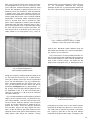
Tone control action of both the bass and treble controls is so precise and well calibrated that we decided to
trace overall response for each of the ten possible settings of each of those controls. The results are displayed in the 'scope photo of Fig. 6. Flat response is re-
Fig. 4 - Playback response of
phono preamp-equalizer section
though our frequency sweep extends only down to 20
Hz, the response continues to roll off below that frequency at a 6 dB per octave rate, exactly as prescribed
by the new IEC standards. If you try to measure the
phono response against the "old" RIAA curve, however, you will find that at 30 Hz it differs from the old
prescribed point-by-point plot by approximately 1 .3
dB In terms of the new and preferred playback curve,
the equalization of the C 27 was so accurate that it
varied by no more than 0.1 dB at any of the remaining
test points measured.
Fig. 5 is a plot of distortion versus frequency (at rated
output) via the high-level inputs, as observed at the
main output terminals. Over the entire spectrum from
20 Hz to 20 kHz, harmonic distortion never exceeded
0.025% and at mid frequencies it measured an extremely low 0.009%. Since the distortion measured
from the phono inputs to the tape outputs was even
lower, we did not bother to plot these results since the
high-level section would govern actual distortion of the
output signals under actual use condition. Though
Fig. 6 - Step-by-step tone control
response characteristics
presented by the center curve of this series and was
measured as flat within 0.5 dB from 1 0 Hz to 23 kHz.
The -3 dB points in response occurred at 4 Hz and 60
kHz. Signal to noise ratio in the high level settings
measured 86 dB below rated output, unweighted, and
19
92 dB with an "A" weighting network inserted, both
figures exceeding published limits of Mclntosh. Volume
control tracking was found to be accurate from left to
right channels within 0.2 dB from maximum settings
down to a -70 dB level
The action of the high and low cut filters is illustrated
in the 'scope photos of Fig 7 While the slope rates are
clearly only 6 dB per octave (we prefer steeper slopes
ourselves), Mclntosh wisely set the c u t - o f f points at
sufficiently high and low frequencies ( 5 0 Hz for the
low-cut and 5 kHz for the high-cut) so that their intro-
Fig. 7 - Low-cut and high-cut filter response
duction into the signal path would not take too big a
"bite" out of musical content or program sources that
require "cleaning up" because of background hiss or
low frequency noise and rumble.
The action of the previously described loudness control is clearly illustrated in the three response plots
Fig. 8 - Action of separate loudness control at "flat"
(upper trace), "mid" and "max" (lower trace) settings
20
shown in Fig. 8. Note that these curves were achieved
with a constant setting of the master volume control
and only the loudness control setting itself was varied,
from one extreme to the other. Total level variation a f forded by this control amounted to approximately 22
dB (each vertical division in this Figure as well as in
Figs. 4, 6 and 7 represents an amplitude difference of
10dB).
Use and Listening Tests
As is true of other Mclntosh components we have
tested in the past, one immediately senses that the C
27 is, first and foremost, a reliably built product and
one that is likely to last for a very long time and require
a minimum of servicing. Controls have a positive and
rugged feel about them and tend to be manipulated
with confidence even by an inexperienced user encountering the product for the first time. We played a
variety of discs through the phono section of the C 2 7 ,
using our recently acquired Shure V 1 5 Type IV cartridge for that purpose. Our record library now contains
a good selection of direct-to-disc records which were
reproduced flawlessly through the C 27 and a high
quality 1 1 0-watt per channel power amplifier plus our
reference loudspeakers. Transient response was
superb and bass passages were tight and totally unmuddied. Attempting to use the phone j a c k we
discovered that it must be powered from the interconnections of the associated power amplifier. In other
words, the C 2 7 , unlike the C 3 2 , does not contain its
own built-in headphone amplifier but rather derives
phone power from the amp-speaker connections which
are brought over to the unit for the switching capability
incorporated in the C 2 7 . A user of the C 27 would
want to utilize this feature in any case, and there is an
"off" position on the C 2 7 ' s speaker switch for
headphone-only listening once these connections are
madeAll in all, Mclntosh seems to have come up with a
brand new preamplifier which should fit nicely into
those systems which are comprised of the finest power
amplifiers, speakers and program source components
and whose owners either prefer to do without such ext r a s as graphic equalizers or expanders or who would
rather add such devices as separate accessories when
and if the need arises. In our opinion, the suggested
price of the new C 27 is not at all inconsistent with the
level of performance achieved by the C 27 or with its
excellent design, construction and control features.
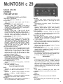
McINTOSH c 29
SOLID STATE
STEREO
PREAMPLIFIER
PERFORMANCE LIMITS and RATINGS
FREQUENCY RESPONSE:
+ 0 -0.5 dB 20 Hz to 20,000 Hz.
DISTORTION:
.02% maximum at rated output level. 20 Hz to
20,000 Hz.
INPUT SENSITIVITY AND IMPEDANCE:
Auxiliary, Tuner, Tape 1, Tape 2, 0.25 volts at
250,000 ohms: Phono 1 and Phono 2, 2 millivolts
(1,000 Hz) at 47,000 ohms and 65 pF; Microphone,
2.5 millivolts at 500,000 ohms.
HUM AND NOISE:
Auxiliary, Tuner, Tape 1, Tape 2, IHFA 100 dB;
unweighted 90 dB below rated output. Phono 1,
Phono 2 IHFA 90 dB; unweighted 80 dB below 10
millivolts input, equivalent to less than 1.0
microvolt at the input terminals. Microphone, 1.5
microvolts at the input terminals.
OUTPUT LEVEL:
Main Output: 2.5 volts with rated input, less than
100 ohms source impedance, to operate into
10,000 ohms or greater. Tape Output: 0.25 volts
with rated input, less than 200 ohms source impedance, to operate into 10,000 ohms or greater.
Headphone/Line: 0.75 volts into 8 ohm load or 2.5
volts into 600 ohm line. 47 ohms source impedance, level controls provided.
VOLTAGE AMPLIFICATION:
Phono 1, Phono 2 at 1 kHz to Main Output 62 dB,
to Tape Output 42 dB, to Headphone/Line Output
72 dB. Auxiliary, Tuner, Tape 1 and Tape 2 to Main
Output 20 dB, to Tape Output 0 dB, to Headphone/Line Output 30 dB. Microphone to Main
Output 60 dB, to Tape Output 40 dB, to Headphone/Line Output 70 dB.
SEMICONDUCTOR COMPLEMENT:
9 Integrated Circuits, 2 Transistors, 11 Silicon
Diodes, 8 Light Emitting Diodes (LED), 1 Silicon
Controlled Rectifier (SCR), 1 Dual Light Dependent Resistor Network (LDR).
AC POWER OUTLETS:
2 automatic current sensing (green), 4 switched
(black)
POWER REQUIREMENT:
120 volts, 50/60 Hz, 15 watts.
FACILITIES AND FEATURES
BASS:
Separate 11 position rotary switches for each
channel, +20 dB to -20 dB at 20 Hz.
TREBLE:
Separate 11 position rotary switches for each
channel. + 18 dB to - 18 dB at 20,000 Hz.
LOUDNESS:
Flat response, or continuously variable loudness
equalization as volume level is reduced.
BALANCE:
Natural balance at center position, attenuation of
left or right channel by rotating control.
VOLUME:
Precision step volume control with left to right
tracking accuracy within 1 dB through its entire
range.
INPUT:
Six positions—Auxiliary 1 and 2, Tuner, Phono 1
and 2, Microphone.
MODE:
Seven positions—Left channel only to both
speakers. Right channel only to both speakers.
Stereo Reverse, Stereo, Mono L + R to left
speaker only, and L + R to right speaker only.
TAPE MONITOR:
Two pushbutton switches. Either of two tape
recorders can be monitored by selecting the Tape
1 pushbutton or Tape 2 pushbutton.
TAPE COPY SWITCH:
Two pushbutton switches. Either of two tape
recorders can be connected to copy from tape
recorder 1 to tape recorder 2 or vice versa.
LF - HF FILTERS:
Reduce unwanted high frequency noise (above 7
kHz) and low frequency rumble etc. (below 50 Hz)
at 12 dB per octave rate.
FRONT PANEL TAPE JACKS:
Allows connection to input and output of a tape
recorder from the front panel.
HEADPHONE JACK:
For listening with either low or high impedance
dynamic stereo headphones. Power to this jack is
supplied by an amplifier in the C 29.
SPEAKER SWITCHES:
Turn Two sets of speakers on or off when properly
interconnected with the accessory Speaker Control Relay. Model SCR-2 (see page 24).
MECHANICAL
SIZE:
Front panel measures 16 inches wide (40.6 cm) by
5-7/16 inches high (13.8 cm). Chassis measures
14-3/4 inches wide (37.5 cm) by 4-13/16 inches high
(12.2 cm) by 13 inches deep (33.0 cm), including
PANLOC shelf and back panel connectors. Knob
clearance required is 1-1/4 inches (3.2 cm) in front
of the mounting panel.
FINISH:
Front panel is anodized gold and black with
special gold/teal nomenclature illumination.
CHASSIS:
Black
MOUNTING:
Mclntosh developed professional PANLOC.
WEIGHT:
21 pounds (9.5 kg) net, 33 pounds (15 kg) in shipping carton.
21
IF YOU DESIGNED A PREAMPLIFIER THAT HAD THE
FLEXIBILITY YOU WANT WITH THE
PERFORMANCE YOU NEED
IT WOULD LOOK LIKE THIS...
C 33 shown in optional walnut veneer cabinet.
Separate LISTEN and RECORD program circuits
Record on up to 3 tape recorders from any connected source or copy from one tape recorder to
another with complete independence from the program being listened to. The RECORD and LISTEN
input selector switches operate without any interaction. The program being recorded can be monitored easily by pushing the monitor pushbutton.
Second generation electronic input switching
Greater source to source isolation with much lower
noise and distortion. Both LISTEN and RECORD input selectors control low DC voltages that electronically control Field Effect Analog switches. Because the FET analog switches are located at the
input, noise, switch clicks and pops are eliminated
and the potential from hum pickup is substantially
reduced.
Five band tone shaping controls in either the RECORD or LISTEN circuits
Five separate controls permit individual musical
spectra shaping in two octave segments to satisfy
personal preference or program limitations. There
is 12 dB plus or minus control at center frequencies of 30, 150, 1,500 and 10,000 Hz. In the center
(detent) position the tone shaping circuits are not
22
active. The overall frequency response of the C 33
is 10 Hz to 100 kHz.
• PROGRAM COMPRESSOR in either the RECORD
or LISTEN circuits
Compression added to a tape recording permits expansion of playback for lower background noise
and increased dynamic range. Compression can be
added to either the RECORD or LISTEN circuit.
•PROGRAM EXPANDER is switched to either the
RECORD or LISTEN circuits
Expansion added to playback of your tape recordings, phonograph records and broadcasts delivers
increased dynamic range and lower background
noise. Also permits the playback of specially encoded records.
• Seven Inputs
Complete facilities for 3 tape recorders, 2 turntables, 1 tuner and 1 other high level source.
• Record Monitor
Momentary action electronic switch allows tape
outputs to be monitored and compared with the original program at the main outputs.
• Signal Processor input and output for both LISTEN
and RECORD circuits
External signal processors can be connected to
modify the program when recording or when listening.
• Low Frequency and High Frequency Filters
The low frequency (LF) filter attenuates the. program material at 12 dB per octave below, 50 Hz to
help eliminate rumble, acoustic feedback and
other similar unwanted noises. Above 7,000 Hz the
high frequency (HF) filter attenuates hiss, scratch
and such unwanted noise at 12 dB per octave.
• Active Loudness Control
Loudness controls typically are simple, passive circuits connected to a portion of the rotation range
of the volume control. As a consequence, loudness
compensation accuracy is dependent on many
variables such as speaker efficiency, amplifier
gain and differences in input level. The C 33 loudness control is continuously variable, operates independently of the volume control, and its contour
is accurately modeled after the Fletcher Munson
family of "Equal Loudness" curves.
• Front Panel Tape Jacks
A fourth tape deck may be plugged into the front
panel without disturbing your permanently wired
system.
• High Accuracy Tracking Volume Control
The volume control is a step attenuator which has
tracking accuracy within 1 dB throughout its entire
range. Such extremely accurate matching is achieved through electronically controlled trimming of
the resistance material deposited on pairs of printed circuits. Tracking accuracy and quiet performance are permanently maintained. Use does not
affect performance as in ordinary volume controls.
• Automatic Power Turn On/Turn Off
Power to the entire stereo system can be controlled from either the front panel power switch or the
turntable's power switch. A current sensing relay
connected to the turntable AC power outlets is
controlled by the turntable power switch. The relay,
in turn controls the AC power to the remainder of
the system. Sensitivity of the circuit is adjustable
to match the current consumption of your turntable.
• Two, new, quiet phono preamplifier circuits
Two turntables can be used simultaneously, listen
to one while recording from the other. New, third
generation IC OP amps are used. Because they
have lower noise and distortion than discrete devices, the C 33 is the quietest phono preamp ever.
• Double shielded phono preamp
Superior performance, even in the presence of
strong interference fields, is assured by the use of
the steel exterior chassis plus an inner shield enclosure of plated steel.
• Triple Shielded Power Transformer
A solid copper band, a silicon steel band and a
mild steel outer casing confines the magnetic field
of the power transformer to reduce the potential for
hum pickup in either the C 33 or associated equipment. This expensive construction removes limitations on how or where you may install your equipment.
• Electronically Regulated Power Supplies
Maintains stable operation even during periods of
low line voltage.
• Power turn on/off Transient Protected
Power turn on and off are electronically time controlled to prevent any thumps, pops or clicks.
• Switched AC Outlets
AC outlets for tape decks, tuners, etc. that turn ON
and OFF with your preamp.
• Auto Muting
To prevent any annoying pops or clicks the main
output is automatically muted when switching.
• Program Output Switching
Rear panel jacks are provided to connect two additional power amplifiers for feeding program material to remote areas. Front panel pushbuttons will
turn the program on or off to the remote amplifiers.
Alternately, the pushbuttons can control remote
speaker systems when used with an accessory
switching relay (the Mclntosh SCR 2).
• LED Function Indicators
Long life solid state indicators show the system
status.
• Unique Flexible Mode Switch
Can be used in seven modes of operation.
• Monitor Amplifier
A wide band, very low distortion 20 watts per channel power amplifier feeds the front panel Headphone jacks, the 600 ohm line outputs and monitor
outputs. Complete protection is assured by the
Mclntosh developed and patented POWER GUARD
and Sentry Monitor circuit. You can listen in private
to headphones with the main power amplifier turned off, use the Monitor Output to feed remote loudspeakers or in association with audio time delay
devices and other applications.
• Full Monitor Amplifier Input Flexibility
Input to the Monitor Amplifier can be selected from
three inputs: the LISTEN circuit, the RECORD circuit, or the external input jacks on rear panel.
• Dual Headphone Jacks
Two pairs of headphones may be powered from the
internal monitor amplifier.
• Modular Construction
Should service be required, it can be done quickly
and easily.
23
PERFORMANCE LIMITS and RATINGS
PREAMPLIFIER SECTION
FREQUENCY RESPONSE
+ 0, -0.5dBfrom20Hzto20,000Hz
MAXIMUM VOLTAGE OUTPUT
10 volts from 20Hz to 20,000Hz
TOTAL HARMONIC DISTORTION
0.01% maximum from 20Hz to 20,000Hz
at rated output
SENSITIVITY
Phono- 2mV for 2.5V rated output
(0.4mV IHF)
High Level- 250mV for 2.5V rated output
(50mV IHF)
SIGNAL TO NOISE RATIO, A-WEIGHTED
Phono- 90dB below 10mV input
(84dB IHF)
High Level- 100dB below rated output
(86dB IHF)
MAXIMUM INPUT SIGNAL
Phono- 100mV
High Level- 10 volts
INPUT IMPEDANCE
Phono- 47k ohms and 65pf capacitance
High Level- 50k ohms
EQUALIZATION CONTROLS
Variable 12dB boost to 12dB cut at center frequencies of 30, 150, 500, 1500, 10k Hz
COMPANDOR RATIOS
From 1:2 compression to 2:1 expansion
LF FILTER
Flat or roll-off at 12dB per octave below 50 Hz.
HF FILTER
Flat or roll-off at 12dB per octave above 7,000 Hz.
SPEAKER CONTROL RELAY
The Mclntosh (SCR 2) Speaker Control relay is used with the Mclntosh C 33 or C 29 stereo preamplifier. It provides the ability to control both the AC
power to a remote amplifier and the ON/OFF func24
MONITOR AMPLIFIER SECTION
CONTINUOUS AVERAGE POWER OUTPUT
20 watts per channel into 8 ohms, from 20Hz to
20kHz, at 0.01% maximum harmonic distortion
FREQUENCY RESPONSE
+ 0 -0.2dB from 20Hz to 20,000Hz
SENSITIVITY
750mV for rated output (170mV IHF), input impedance is 27K ohms
SIGNAL TO NOISE RATIO, A-WEIGHTED
100dB below rated output (87dB IHF)
GENERAL INFORMATION
SEMICONDUCTOR COMPLEMENT
31 Bipolar Transistors
76 Field Effect Transistors
35 Integrated Circuits
107 Diodes
1 Silicon Controlled Rectifier (SCR)
AC POWER OUTLETS
2 turntable current-sensing, 100 watts, green
4 switched, 1200 watts total, black
POWER REQUIREMENTS
120 volts, 50/60 Hz, 25 to 85 watts
MECHANICAL INFORMATION
SIZE:
Front panel measures 16 inches wide (40.6 cm)
by 5-7/16 inches high (13.8 cm). Chassis measures
15 inches wide (38.1 cm) by 5 inches high (12.7cm)
by 13 inches deep (33.0 cm), including PANLOC
shelf and back panel connectors. Knob clearance
required is 1-1/2 inches (3.81 cm) in front on the
mounting panel.
WEIGHT:
26 pounds (11.8 kg) net, 38 pounds (17.2 kg) in
shipping carton
XR 19
tions of the Main and Remote loudspeakers. Preamplifier front panel pushbuttons provide the control
for the SCR 2 through a low voltage supply in the preamplifier.
McINTOSH MR 75
AM-FM STEREO TUNER
The Mclntosh MR 75 AM-FM Stereo Tuner is a
superb tuner using the latest high technology circuits. This fine tuner will discover more FM stations
with good quality than ever before.
FM AUTOMATIC FREQUENCY LOCK
The Automatic Frequency Lock (AFL) is a
patented Mclntosh circuit that activates when you
tune to the center frequency of an FM station. When
the center ON-STATION vertical LED indicator
lights, there will be no drift from accurate tuning, insuring minimum distortion and best performance.
AUTOMATIC STEREO NOISE SUPPRESSION
When listening to weak or distant FM stations, optimum stereo separation and signal to noise ratio is
automatically provided by a third generation phase
locked loop stereo decoder.
UNIQUE AM TUNER SECTION
The AM tuner's design is unique for a
superheterodyne receiver. It has constant selectivity, constant sensitivity and high image rejection
across the band. There is no loss of frequency
response at the low end of the band, the only AM circuit with all these performance features.
PERFORMANCE LIMITS AND RATINGS
FM SECTION
TUNING:
88 to 108 MHz
ANTENNA INPUTS:
One 300W balanced and one 75W unbalanced.
INTERMEDIATE FREQUENCY:
10.7 MHz
USABLE SENSITIVITY:
2mV (11.2 dBf) IHF
QUIETING SENSITIVITY:
5mV (19.1 dBf) IHF -50 dB (Mono)
50mV (39.5 dBf) IHF -50 dB (Stereo)
SIGNAL TO NOISE RATIO:
70 dB IHF minimum both Mono and Stereo
HARMONIC DISTORTION:
0.18% (Mono) IHF maximum
0.38% (Stereo) IHF maximum
ALTERNATE CHANNEL SELECTIVITY:
75 dB IHF minimum
IMAGE REJECTION:
100 dB IHF minimum
STEREO SEPARATION:
45 dB minimum at 1 kHz
AUDIO FREQUENCY RESPONSE:
20 Hz to 15 kHz +0, -1 dB
CAPTURE RATIO:
1.8 dB
SELECTIVITY:
75 dB IHF minimum
SPURIOUS REJECTION:
100 dB IHF minimum
SCA REJECTION:
60 dB minimum
AM SECTION
SENSITIVITY:
75mV IHF with external antenna
SIGNAL TO NOISE RATIO:
45 dB minimum IHF or 55 dB at 100%
modulation
FREQUENCY RESPONSE:
+ 0 -6 dB from 20 Hz to 3500 Hz
HARMONIC DISTORTION:
0.8% maximum at 30% modulation
ADJACENT CHANNEL SELECTIVITY:
30 dB minimum IHF
IMAGE REJECTION:
65 dB minimum from 550 kHz to 1600 kHz
GENERAL INFORMATION
AUDIO OUTPUT:
Variable:
2.5V into 47kW
Fixed:
1V into 47kW
AUDIO HUM:
75 dB down from 100% modulation
POWER REQUIREMENT:
120 Volts 50/60 Hz, 20 Watts
SEMI CONDUCTOR COMPLEMENT:
22 Bipolar Transistors
4 Field Effect Transistors
23 Silicon Diodes
15 Integrated Circuits
19 LED's
2 Bridge Rectifiers
MECHANICAL INFORMATION
SIZE:
Front panel measures 16 inches wide (40.6 cm) by
5 7/16 inches high (13.8 cm). Chassis measures 14
3/4 inches wide (37.5 cm) by 4 13/16 inches high
(12.2 cm) by 13 inches deep (33 cm), including connectors. Knob clearance required is 1 1/4 inches
(3.2 cm) in front of mounting panel.
FINISH:
Front panel is anodized gold and black with
special gold/teal nomenclature illumination.
Chassis is black.
MOUNTING:
Exclusive
PANLOC
WEIGHT:
Mclntosh
developed
professional
23 pounds (10.43 kg) net, 35 pounds (15.88 kg) in
shipping carton.
25
15 YEARS OF BASIC CIRCUIT AND CONCEPT RESEARCH
HAS DEVELOPED THE TECHNOLOGY
NECESSARY FOR A TRULY LOW DISTORTION
FM TUNER WITH VARIABLE SELECTIVITY . . .
THE MCINTOSH MR 78!
A FORTRAN computer program using an
algorithm that took six years to develop was used in
its design. The mathematical complexity of the filter
design procedure is almost beyond belief. Using a
process called "numerical integration in the complex S-plane," a high speed IBM computer was used
on the design of the IF filter. A human engineer,
working twenty-four hours a day and seven days a
week, would have taken 300 years to finish this work
. . . assuming he made no mistakes!
VARIABLE SELECTIVITY
The MR 78 has variable selectivity. In SUPERNARROW the IF bandwidth is 210 kHz wide at 60 dB
down and permits tuning stations that are impossible on ordinary tuners. The great number of stations
crowding the FM band requires a tuner with variable
selectivity.
In the NORMAL position, a very low distortion
8-pole filter is used in the IF circuit.
Mclntosh research is a continuous program of exploration for technology that permits performance
improvement and greater value for you. This
unrestricted research program developed the
technology necessary for the realization of these
design concepts for the MR 78.
THE DISTORTIONLESS IF FILTER
Ever since the beginning of FM, research
engineers have realized that constant delay IF filters
equivalent to linear-phase were necessary for low
distortion reception. Crude approximations to constant delay have always been used in FM tuners - with
disappointing results. So-called "Butterworth" or
"Legendre" filters offer only a fair compromise with
respect to delay error. Crystal and ceramic filters,
usually based on the "Chebychev" model, work fairly well and give good selectivity, but none of these
are constant delay linear-phase, filters. Commercial
tuners using these filters can show 5% stereo IM
distortion at 100 % modulation. The filters used in
most of todays tuners can have delay errors up to
100%! The IF filter in the MR 78 has a delay error of
less than 1% from antenna input to discriminator
output! In its useful bandpass, it is a true
mathematical approximation to linear-phase. It is
the world's finest selective, linear-phase, minimumphase shift filter.
26
The NARROW position adds a sharp 8-pole filter
to the NORMAL IF filter to yield a low distortion (less
than 0.2%), highly selective 16-pole composite IF
filter.
SUPER-NARROW position adds a 4-pole 4-zero
crystal filter to the two other IF filters. SUPER NARROW permits receiving distant stations which are on
channels adjacent to local stations. With an adequate FM antenna there are usable signals never
heard before with ordinary FM tuners.
The MR 78 tuner uses linear phase filters at the
NORMAL and the NARROW positions of the SELECTIVITY switch settings.
LINEAR PHASE BRIDGE DISCRIMINATOR
The excellence of the IF filter would be useless if
it had to work into an ordinary FM detector. Thus a
new detector with suitably low distortion had to be
developed. A search of the available literature
revealed a little-known bridge circuit with a
theoretical distortion of zero! However, designing a
practical working circuit for a commercially feasible
stereo tuner took some doing. A U.S. patent is held
by Mclntosh on this circuit.
Distortion performance of the new Mclntosh bridge
detector is close to" the theoretical zero. In addition
to its excellent distortion performance, the bridge
detector also exhibits a capture ratio close to 0 dB.
FRONT END
Instead of using a conventional, easily overloaded
transistor or FET as a straight RF amplifier, the MR
78 uses a rugged Junction Field Effect Transistor as
an impedance converter to drive a 5-watt power transistor. This combination, a cascode circuit, makes
the RF amplifier virtually impossible to overload or
cross-modulate. As an example, if you are tuned to a
3 microvolt signal at 96.3 MHz, the MR 78 will reject
signals elsewhere on the dial which are at least,
4,000,000 times stronger. Thus, a 12 volt signal
received at 104.3 MHz would not interfere with the
signal at 96.3 MHz.
The front end oscillator uses a high-Q ceramic
form tank coil. It is free from spurious radiation, and
operates at high efficiency.
Adding to the superior design of the front end is
the integrated circuit balanced mixer. It is practically impossible to overload. Oscillator pulling, cross
modulation, and other types of distortion so common in ordinary transistor or FET mixers is minimized.
PERFORMANCE LIMITS and RATINGS
TUNING RANGE:
88 to 108 MHz.
ANTENNA INPUTS:
300 ohms balanced; 75 ohms unbalanced.
INTERMEDIATE FREQUENCY:
10.7 MHz.
SENSITIVITY:
2mV for 35 dB quieting; 2.5 mV at 100% modulation
(± 75 kHz deviation) for 3% total noise and harmonic distortion.
SIGNAL TO NOISE RATIO:
75 dB below 100% modulation.
HARMONIC DISTORTION:
0.2% mono or stereo at 100% modulation, 20 Hz
to 15,000 Hz. Typically, 0.05% at 1,000 Hz.
DRIFT:
25,000 Hz for the first two minutes; thereafter
5,000 Hz at 25° C in 24 hours.
FREQUENCY RESPONSE:
Mono: ± 1 dB 20 Hz to 20,000 Hz with standard
de-emphasis, (75 mS); Stereo: ± 1 dB 20 Hz to
15,000 Hz with standard de-emphasis (75 mS).
CAPTURE RATIO:
0.25 dB detector only; 2.5 dB complete tuner.
SELECTIVITY: Switch Setting:
NORMAL
NARROW
SUPER NARROW
Adjacent Channel
7 dB
22 dB
55 dB
Alternate Channel
55 dB >90 dB >>90 dB
SPURIOUS REJECTION:
100 dB IHF.
IMAGE REJECTION:
100 dB at 88 to 108 MHz (IHF).
INTERMODULATION DISTORTION:
0.2% mono or stereo for any combination of frequencies from 20 Hz to 15,000 Hz with peak
modulation equal to 100% or less. Typically 0.1 %.
MAXIMUM SIGNAL INPUT:
12 volts across 300 ohm antenna terminals will
not increase harmonic or intermodulation distortion.
AUDIO HUM:
75 dB down from 100% modulation..
MUTING:
70 dB noise reduction between stations.
MUTING THRESHOLD (Typical):
DISTANT 5 mV; LOCAL 20 mV
SCA FILTER:
50 dB down from 67 kHz to 74 kHz; 275 dB per octave slope.
STEREO SEPARATION:
40 dB at 1,000 Hz.
STEREO FILTER (Typical):
10 dB noise reduction in Position 1.
20 dB noise reduction in Position 2.
AUDIO OUTPUT:
Front Panel Controlled: 2.5 volts into 47,000 ohms;
Fixed Output: 2.5 volts into 47,000 ohms, 1.0 volts
into 600 ohms.
All tuner performance limits were measured with SELECTIVITY
switch set at NORMAL, unless otherwise slated.
GENERAL
POWER REQUIREMENT:
120 volts, 50/60 Hz 35 watts.
SEMICONDUCTOR COMPLEMENT:
3 JFET, 2 MOSFET, 17 Bipolar Transistors, 43
Diodes, 4 Integrated Circuits.
MECHANICAL
SIZE:
Front panel: 16 inches wide (40.64 cm) by 5-7/16 inches high (13.81 cm); Chassis: 15 inches wide
(38.1 cm) by 13 inches deep (33.02 cm), including
PANLOC shelf and back panel connectors; Knob
Clearance: 1-1/2 inches (3.81 cm) in front of mounting panel.
FINISH:
Front panel: Anodized gold and black with special
gold/teal panel nomenclature illumination;
Chassis: Chrome and black.
MOUNTING:
Mclntosh developed professional PANLOC.
WEIGHT:
27 pounds (12.25 kg) net, 39 pounds (17.69 kg) in
shipping carton.
27
Electronic Laboratories'
PRODUCT
ANALYSIS
THE McINTOSH MR78
FM/FM STEREO TUNER
Fig. 1 — Front view
MANUFACTURER'S
PUBLISHED
LIMITS (SPECIFICATIONS):
PERFORMANCE
Tuning Range: 88 to 108 MHz. Antenna Inputs: 300 ohms
balanced; 75 ohms unbalanced. Intermediate Frequency
(IF): 10.7 MHz Sensitivity: 2 mV for 35 dB of quieting;
2.5 mV at 100% modulation (± 75 kHz deviation) for 3%
total noise and harmonic distortion. Signal to Noise Ratio:
75 dB below 100% modulation. Harmonic Distortion: 0.2%
20 Hz to 15,000 Hz, mono or stereo at 100% modulation.
Typically, 0.05% at 1000 Hz. Drift: 25,000 Hz for the first
two minutes; thereafter 5,000 Hz at 25° C in 24 hours.
Frequency Response: MONO ± 1 dB 20 Hz to 20,000 Hz
with standard deemphasis, (75 mS). STEREO ±1 dB 20 Hz
to 15,000 Hz with standard deemphasis, (75 mS). Capture
Ratio: 0.25 dB detector only; 2.5 dB complete tuner. Selectivity (IHF): Adjacent Channel: set switch to: normal, 7
dB; narrow, 22 dB; super narrow, 55 dB. Alternate Channel: set switch to: normal, 55 dB; narrow, 90 dB; super
narrow, 90 dB; super narrow, 90 dB. Spurious Rejection:
100 dB IHF. Image Rejection: 100 dB, 88 to 100 MHz,
(IHF). Intermodulation Distortion: 0.2% mono or stereo
for any combination of frequencies from 20 Hz to 15,000
Hz with peak modulation equal to 100% or less. Typically
0.1%. Maximum Signal Input: 12 volts across 300 ohms antenna terminals will not increase harmonic or intermodulation distortion. Audio Hum: 75 dB down from 100% modulation. Muting: 70 dB noise reduction between stations.
Muting Threshold: (Typical): Distant position 5 mV; Local
position 20 mV. SCA Filter: 50 dB down from 67 kHz to
74 kHz; 275 dB per octave slope. Stereo Separation: 40 dB
at 1,000 Hz. Stereo Filter: (Typical): 10 dB noise reduction in Position 1; 20 dB noise reduction in Position 2.
Audio Output: Front panel controlled: 2.5 volts into
47,000 ohms. Fixed output: 2.5 volts into 47,000 ohms;
1.0 volt into 600 ohms. (All tuner performance limits were
measured with SELECTIVITY switch set at NORMAL, unless otherwise stated.)
GENERAL SPECIFICATIONS:
Power Requirements: 120 volts, 50/60 Hz, 35 watts. Semiconductor Complement: 3 J FET's. 2 MOS FET's, 17 Bipolar Transistors, 43 Diodes, 4 Integrated Circuits.
MECHANICAL SPECIFICATIONS:
Size: Front Panel: 16 inches wide (40.64 cm) by 5-7/16
inches high (13.81 cm); Chassis: 15 inches wide (38.1 cm)
by 13 inches deep (33.02 cm), including PANLOC shelf
and back panel connectors; Knob clearance 1-1/2 inches
(3.81 cm) in front of mounting panel. Weight: 27 pounds
(12.25 kg) net, 39 pounds (17.69 kg) in shipping carton.
Finish: Front panel; Anodized gold and black with special
gold/teal panel nomenclature illumination; Chassis: Chrome
and black. Mounting: Mclntosh developed professional
PANLOC.
Most of the semi-technical literature intended tor audiophile-consumer education deals with the specifications of
an FM or a stereo FM tuner as though each were mutually
independent of the others. For example, we are at once
told that "good selectivity" (the ability to tune to stations
closely spaced in frequency without encountering interference from nearby stations on the dial) and wide bandwidth as well as low distortion are mutually exclusive parameters. We are also led to believe that a tuner "should have
ultra low harmonic or intermodulation distortion", but we
are hardly ever told that such low distortion can only be
achieved if the IF bandwidth of the tuner is sufficiently
broad (and linear in phase) to accommodate the upper
modulation sidebands of the incoming signal which may
well extend well beyond the nominal 150 kHz which is
supposed to represent the "maximum bandwidth" of a given
FM channel. But if bandwidth is broadened to accommodate such extreme sidebands (which occur particularly during stereo FM transmissions), how is it possible to achieve
high orders adjacent channel (or even alternate channel)
selectivity? Excellent stereo separation at high audio frequencies is also dependent upon adequate bandwidth, so
that again, such high orders of separation are in conflict
with high orders of selectivity. What's to be done? Most
tuner manufacturer's content themselves with a series of
trade-offs. Selectivity figures are made high enough (without
sacrificing low distortion and good separation) so that in
most listening areas adjacent-channel or co-channel interference will not pose much of a problem most of the time.
Mclntosh has attacked the problem in a more logical
and direct method — by providing variable selectivity on
their MR 78 tuner. But more of this shortly.
The front panel of the Mclntosh MR 78 maintains the
traditional "Mac" look of "black glass" and features that
company's well known PANLOC mounting method (shelves
and shelf mounting brackets, together with necessary
mounting hardware are, as usual, supplied) as pictured in
Fig. 1. The large, illuminated dial area at the upper center
of the panel has a linear dial scale, calibrated at every half
MHz, as well as a 0-100 logging scale for easy referencing
of favorite stations. The smooth traveling dial pointer is
Printed With The Permission Of Electronic Laboratories
28
illuminated over a portion of its length. Also located within
the dial opening are symmetrically positioned center-ofchannel and signal-strength meters. To the left of the dial
area are two rectangular areas denoted as "function" and
"selectivity". Illuminated words "stereo", "filter", and
"muting" appear (when selected) in the upper area, while
the lower area is illuminated with either the notation
"-7 dB", "-22 dB" or "-55 dB". These correspond to the
three selectivity settings of the selectivity switch just
below. The dB numbers represent adjacent channel selectivity and should not be confused with the more familiar
alternate channel selectivity values which are, of course,
much greater. A large tuning knob, coupled to a blacklashfree flywheel and dial string arrangement, is located to the
right of the dial area opening.
In addition to the selectivity switch, other rotary controls
along the bottom section of the front panel include a meter
selector switch which chooses either the signal strength or
multipath indication function of the signal-strength meter,
a filter switch which, in addition to having an "off" position, has two settings for noise reduction during weak-signal
stereo FM reception, a muting switch, with positions for
local and distant reception (which varies the muting threshold), a mode switch with "stereo only", mono, and
"stereo auto" positions and a volume control which also
turns power on and off to the tuner.
The rear panel of the MR 78 has a pair of test points,
as illustrated in Fig. 2., which are intended for use with
the Mclntosh Maximum Performance Indicator, an accessory product marketed by that company. A fuesholder cap
is also accessible from the rear for replacement, if necessary,
of the tuner's 0.5 ampere slo-blow line fuse. Push-type
Fig. 2 — View of back panel
terminals are supplied for 300-ohm antenna transmission
line connection, while a 75-ohm coaxial connector is offered
for connection of that type of transmission line. Two sets
of audio output jacks (one pair for fixed output, the other
controlled by the front-panel volume control) and one
convenience AC receptacle complete the rear panel layout.
Internal Construction and Circuit Highlights
As can be seen in the internal view of the chassis, Fig. 3,
the Mclntosh MR 78 is extensively shielded. Six major
circuit board modules are used in addition to the RF front
end. These include the IF circuit board, the selectivity selection junction board, the multiplex section, the detector circuit board, the output amplifier board and the power supply
circuit board. The front end utilizes a 5-section tuning
capacitor. A junction FET is used as impedance converter
to drive a 5-watt power transistor in the RF stage for high
overload capability. An antenna matching circuit at the RF
input has a two-position selectable switch which alters the
RF bandpass characteristics of the input circuit. The switch
positions are labelled "Lo Gain" and "Hi Gain", a bit confusing unless the user reads the manual carefully and discovers that the gain references refer to the antennas which
might be used with the tuner. Thus, the Lo Gain position is
intended for use in seeking out distant or weak signals
Fig. 3. — View of chassis layout
while, in most applications, the "Hi Gain" position should
be used since it yields the lesser amount of RF signal at the
input to the RF amplifier stage, as well as a sharper bandpass
characteristic.
A block diagram of the RF and IF sections of the MR 78
is reproduced in Fig. 4. A balanced integrated circuit mixer
stage is used as a further safeguard against possible overload
and to reduce oscillator pulling. Its 0.7 MHz output is
coupled to the IF amplifier section by means of a bifilar
transformer. Linear phase filters are used in both the
NORMAL and NARROW selectivity settings of the MR 78,
while for the SUPER-NARROW selectivity setting, a
4-pole, 4-zero crystal filter having constant delay, is introduced into the IF chain. Mclntosh developed a new type of
FM detector for this tuner which they call a linear phase
bridge discriminator. It uses a balanced transmission line
bridge in conjunction with a differential voltage doubling
circuit to achieve ultra-low orders of distortion in the
demodulated FM audio signals.
A block diagram of the Multiplex and Audio Sections is
illustrated in Fig. 5. An IC audio amplifier with over 120
dB of negative feedback in two feedback loops is used to
drive the stereo demodulator. Muting, "stereo only" tuning
and automatic mono/stereo switching are all functions
which are performed within the stereo decoder circuitry.
A stereo filter circuit follows the matrix decoder and deemphasis networks to reduce noise when tuning to weak
stereo stations. This filter employs a twin-T bandpass
filter design to suppress noise while only minimally affecting
stereo separation and imaging. The audio amplifier section
consists of a pair of two-transistor amplifiers, one for each
channel. Each amplifier delivers 2.5 volts to the fixed output
jacks and to the volume control sections which feed the
29
variable output jacks. The power supply section consists of
a 24-volt regulated supply which uses electronic filtering
and supplies power to all signal stages, while a second, halfwave rectifier supply also equipped with electronic filter
circuits feeds the necessary DC voltages to the multiplex
decoder section.
Laboratory Measurements
Although most listening situations require selectivity
settings of NORMAL on the MR 78, we decided to measure
performance in this setting as well as the NARROW selectivity setting. In the NORMAL setting, IHF sensitivity measured 2.0 mV (11.2 dBf) and 50dB quieting was reached with
an input signal strength of 3.0 mV (14.7 dBf) in mono.
Referring back to the published specifications, readers
will note that Mclntosh has not as yet seen fit to bring their
specs into line with the newly adopted IHF/IEEE/EIA FM
Tuner Measurement standards. Thus, no claim is made for
the 50 dB quieting sensitivity, for example, and Mac offers
us a 35 dB quieting point instead. While we recognize that
Mclntosh has, in the past, differed with the rest of the industry in the matter of publishing specifications, we do feel
that the new tuner standards are worth following and would
hope that if they have not already done so, Mclntosh would
bring their published specs into line so that they might be
easily compared with those of other companies. Be that
as it may, 3.0 mV (14,7 dBf) is a very respectable figure for
50 dB quieting. Stereo sensitivity was 4.5 mV (18.3 dBf),
at which signal strength in stereo was sufficient to cause
nearly 35 dB of quieting. 50 dB of quieting in stereo was
attained with an input signal of 32 mV (35.3 dBf). Ultimate
S/N in mono was an incredibly high 81 dB (we never
thought our signal generator could read that low — now we
know it can), while in stereo, best quieting for strong
signals was 73 dB. Total harmonic distortion in mono was a
low 0.06%, while in stereo, for the same strong signals used,
THD read 0.1% at 1kHz. Curves of results obtained in the
Normal selectivity setting are plotted in Fig. 6.
Switching to the NARROW selectivity setting, S/N readings in both mono and stereo remained virtually the same,
but, as was to be expected, THD readings increased slightly,
to 0.08% for mono and 0.35% for stereo. These results are
shown in Fig. 7.
Returning to the NORMAL selectivity setting, we measured a capture ratio of 1.8 dB. Alternate channel selectivity
was 57 dB for this setting, while image and spurious rejection
were both in excess of 100 dB (the limits of our test equipment). Maximum deviation from ideally flat frequency response, for both mono and stereo, was less than 1.0 dB,
with the deviation approaching that number at 1 5 kHz but
remaining within 0.2 dB at frequencies from 10 kHz down
to 50 Hz. Muting threshold occurred at 7.0 mV for the "distant" position, 30 mV for the "local" position. Stereo
switching occurred at around 4.0 mV (17.2 dBf).
Stereo separation measured 52 dB at mid frequencies for
the normal selectivity position, decreasing to 43 dB at 100
Hz and 36 dB at 10 kHz, as plotted in Fig. 8. In order to
properly ascertain the THD produced by the tuner at high
modulating frequencies it was necessary for us to employ
our spectrum analyzer and to "sum" the harmonic products
mathematically to arrive at the 0.14% THD figure shown
30
for a 10 kHz modulating frequency. If this is not done,
super-audible products (not properly identifiable as harmonic distortion) "cloud" the single-reading measurement
that is obtained on a conventional meter-type distortion
analyzer.
Fig. 9 is a plot of separation versus frequency with the
selectivity control set to the NARROW position. Separation
naturally suffers somewhat when this narrow setting is
used, but remains well above 30 dB for most frequencies
tested. Distortion in stereo also rose somewhat in the narrow
setting, as shown in the curves of Fig. 9. While in mono,
THD remained incredibly low at mid-frequencies even when
the narrow setting of the selectivity switch was used.
Sub-carrier product rejection was so good that it was not
even necessary to use the recommened 15 kHz low-pass
filters for all of our high-frequency noise and distortion
measurements, except as already noted for the 10 kHz
readings. Audio output level was exactly 2.5 volts, as
claimed, for a 100% modulation signal at the fixed output
terminals. Since our own signal generating equipment is
limited to 0.2 volts output, there was no way for us to
verify Mclntosh claims regarding 12 volt antenna input
overload capability, though we have no reason to doubt
the claim, based on subsequent strong-signal listening tests.
We purposely carted the tuner over to a mid-city location
where we have access to a listening room that is just a few
blocks away from several high-powered FM transmitters.
INPUT - MICROVOLTS ACROSS 300 OHMS
Mono: (1) Total Harmonic Distortion
Stereo: (3) Total Harmonic Distortion
(THD)
(THD)
(2)
Signal To Noise Ratio (S/N)
(4) Signal To Noise Ratio (S/N)
Fig. 6 — FM quieting and distortion characteristics
(with selectivity switch set to "NORMAL")
INPUT - MICROVOLTS ACROSS 300 OHMS
Mono: (1) Total Harmonic Distortion
[THD)
(2)
Signal To Noise Ratio (S/N)
Stereo. (3) Total Harmonic Distortion
(THD)
(4)
Signal To Noise Ratio (S/N)
Fig. 7 - FM quieting and distortion characteristics
(with selectivity switch set to "NARROW")
if he could have heard FM the way we heard it over the
Mac MR 78.
F R E Q U E N C Y - HZ
Mono: (1) Total Harmonic Distortion (THD)
Stereo (2) Total Harmonic Distortion (THD)
Fig. 8 — Separtion and distortion versus frequency
(with s e l e c t i v i t y switch set to "NORMAL")
There was only one instance where we found it necessary
to use the SUPER-NARROW position of the selector switch,
and that was when we were trying to listen to a weak signal originating some 120 miles from our listening location
— one nestled between a stronger signal 200 kHz below it,
and a much stronger local station, 200 kHz on the higher
side of the dial. If you've ever tried to receive that kind
of signal on a lesser tuner, you'll know what we mean. In
any case, when we did switch to the SUPER-NARROW
position, we actually were able to listen to the desired
distant station and distortion, though audibly higher,
was still at tolerable levels.
FREQUENCY - HZ
Mono: (1) Total Harmonic Distortion (THD)
Stereo: (2) Total Harmonic Distortion ( T H D )
Fig. 9 - Separation and distortion versus frequency
(with selectivity switch set to "NARROW")
Previously, we had measured signal voltages of 2 to 3 volts
at that location and found that most tuners did exhibit
cross-modulation and other overload effects. With the
"Mac" tuner, we were able to clearly separate closely
spaced high-signal stations on the dial with nary a trace of
interference from other strong-signal stations in the same
vicinity.
Other Use and Listening Tests
Back in our lab (some 20 miles from the city), we began
to appreciate the importance of that selectivity switch on
the front panel. If you are an inveterate FM DX-er, you will
be amazed (as we were) at how many signals you can separate and receive clearly by using the narrow (and at times
even the super-narrow) selectivity switch positions on the
MR 78. Here is a tuner that doesn't compromise between
low distortion and wide bandwidth. 55 dB of selectivity
(that claimed in the NORMAL setting) is no problem if you
are not plagued by adjacent and alternate channel signals.
In fact, the normal setting, coupled with those linear phase
filters in the IF section, rendered the kind of reception
from the few good quality stations that we have in our listening area that we had often dreamed about- Program
quality varied, of course, but when we were fortunate
enough to tune to a live concert (yes, we still do have some
live FM programming in this area, albeit at midnight each
night), the results were truly astounding. We had the feeling that the late Major Armstrong, too, would have smiled
31
THE MOST FLEXIBLE CONTROL SYSTEM
EVER FOR A DIGITAL DISPLAY
PROFESSIONAL FM TUNER
The Mclntosh MR 80
Engineering direction dictated a tuner design
governed by insistence on great flexibility and ease
of use. This had to be done while designing for great
sensitivity and the world's best selectivity in keeping with the needs of low distortion. These values
were achieved. They retain the Mclntosh reputation
for outstanding performance, long life and reliability.
To assure long term trouble free operation, tuning
a station on the MR 80 is achieved electronically.
The MR 80 can be tuned four different ways:
1. Manual tuning by rotating the main tuning knob
2. Auto Scan automatically searches for the next
available station up or down the dial
3. Presets allow you to select the four most listened
to stations at the touch of your finger tip
4. Remote Scanning will allow the MR 80 to be tuned
to a station from a wired remote location.
Two separate antenna systems can be connected
to the MR 80: 1) An outdoor or indoor FM antenna, or
2) a cable from your local cable company. The antenna selection is controlled by an electronic switching
device.
The MR 80 uses electronic varactor tuning instead
of the more conventional mechanically ganged variable tuning capacitors. Variable tuning capacitors
can with age collect dust and dirt, reducing their performance. Mclntosh uses double varactor diodes to
provide the necessary tracking between the different tuned RF stages. When a weak distant station
is adjacent to a strong local station the Preselector
switch will add in an additional tuned circuit providing an extra degree of selectivity to reduce the interference from the adjacent strong station.
After the RF amplifier two paralled tuned circuits
are used to provide the proper load impedance for
the bipolar transistor. These two tuned circuits
greatly improve the image rejection and overload
performance of the tuner, as well as increasing the
RF selectivity.
32
An innovative new lock circuit was developed for
use in the MR 80. This new circuit allows correct tuning without the use of a center tune meter. The MR
80 will be correctly tuned regardless of the stations
transmitted signal as related to its assigned frequency. Two operational amplifiers cause the lock
circuit to track a station even if it drifts 1 MHZ.
The mixer is a balanced matched dual J-FET and
bipolar transistor circuit.
After the mixer the signal is electronically switched to go either directly to the IF amplifier or to go
through a quartz crystal filter. The MR 80 has the narrowest IF bandwidth ever used in a stereo tuner. It is
the correct width to let just one FM station through.
The excellent selectivity of the MR 80 (210 kHz wide
at 60 dB down) permits tuning stations that are impossible to receive on ordinary tuners.
The SUPER NARROW selectivity position adds a 4
pole - 4 zero crystal filter to the other 5 IF filters.
SUPER NARROW permits listening to stations not
heard with most other FM tuners. The 5 stages of IF
amplification provide the necessary gain to reduce
noise in the signal and the interference from other
stations. They are piezoelectric fixed frequency
filters in place of normal tuned circuits. An advantage the IF stages will always stay in alignment,
even with age.
The signal strength indicator column is the sum of
all IF stages instead of just one it indicates the
signal strength throughout the entire IF system.
The selectivity section of the IF amplifier is the
LIMITER with a total gain of 80 dB. The use of very
high gain in the limiter circuit produces hard limiting
with very good impulse noise rejection. Limiter
bandwidth is greater than 50 MHz, producing excellent detector capture characteristics.
A broadband Foster-Seeley discriminator is used
as the detector coupled with a broadband limiter to
produce unmeasurable noise and distortion.
The heart of the multiplex section is a new third
generation phase locked loop (PLL) stereo decoder
integrated circuit (IC). This PLL IC incorporates two
special systems, an automatic variable separation
control circuit to reduce background noise when
receiving weak stereo stations, and tri-level digital
waveform generation which eliminates interference
from SCA signals and from the sidebands of adjacent channel FM signals.
The variable separation control is operated from
the IF amplifier's signal strength detector. A smooth
transition is provided from mono to stereo or from
stereo to mono at weak signal levels to provide the
optimum signal to noise ratio and best stereo
separation for the prevailing signal conditions. The
circuit operates only during stereo reception. It
switches automatically to monophonic if the 19 kHz
pilot tone is absent.
Additional advantages of the phase locked loop
stereo demodulation are the elimination of inductors to minimize drift, integral lamp driving capability to indicate the presence of the 19kHz pilot carrier,
excellent channel separation over the entire audio
frequency range, extremely low distortion, low output impedance, and transient-free mono/stereo switching.
Following the MPX decoder is the three position
de-emphasis switch. The three different positions
allow the MR 80 to be used in North America with
standard 75ms de-emphasis and in Western Europe
and the Far East with 50ms de-emphasis. A 25ms position is provided for use with an external noise reduction devices.
An electronic blend filter circuit, using two J-FETs
of a quad J-FET package, reduces out of phase noise
when in the stereo mode and when tuned to a weak
station. The filter is a twin-T bandpass that blends
the high and low frequencies, leaving separation
unaffected at mid-frequencies. This results in a
greatly improved stereo image when the filter is required.
Special design attention has been given to the
power supply section. Nine separate power circuits
are used. Six of these are regulated to prevent loss
of performance during a brown out.
PERFORMANCE LIMITS and RATINGS
TUNING:
88 to 108 MHz
ANTENNA INPUTS:
One 300W balanced or two 75W unbalanced.
INTERMEDIATE FREQUENCY:
10.7 MHz
SENSITIVITY:
9.3 dBf (1.6mV) for 35 dB of quieting
14.7 dBf (3mV) for 50 dB of quieting
13.2 dBf (2.5mV) for 3% total noise and harmonic
distortion
SIGNAL TO NOISE RATIO:
75 dB below 100% modulation
HARMONIC DISTORTION:
0.2% 20 Hz to 15 kHz, mono or stereo
Typically, 0.08% at 1000 Hz
INTERMODULATION DISTORTION:
0.15% mono or stereo for any combination of frequencies from 20 Hz to 15,000 Hz with peak
modulation equal to 100% or less. Typically 0.1 %
FREQUENCY RESPONSE:
Mono and Stereo ± 1 dB 20 Hz to 15 kHz with 75,
50 or 25mS de-emphasis
CAPTURE RATIO:
1.5 dB
SELECTIVITY:
Narrow
Super Narrow
Adjacent channel
8 dB
60 dB
110 dB
Alternate channel
90 dB
SPURIOUS REJECTION:
110 dB
TUNER IM (RF):
-23dBm for 2 signals 1 MHz apart
TUNER INTERCEPT POINT:
-10 dBm 75W
IMAGE REJECTION:
90 dB
MAXIMUM SIGNAL INPUT:
8 volts across 75W (1W) antenna terminal will not
increase harmonic or intermodulation distortion.
AUDIO HUM:
75 dB down from 100% modulation
MUTING:
70 dB noise reduction between stations
MUTING THRESHOLD:
2mV to 1000mV
SCA REJECTION:
60 dB minimum
STEREO SEPARATION:
50 dB to 1000 Hz
STEREO FILTER:
10 dB noise reduction
AUDIO OUTPUT:
Variable: 2.5V into 47k
Fixed: 1V into 47k
GENERAL INFORMATION
POWER REQUIREMENTS:
120 volts 50/60 Hz. 25 watts
SEMICONDUCTOR COMPLEMENT:
57 Transistors, 68 Integrated Circuits, 81 Diodes,
4 LED Displays, 18 LED's, 7 Neon Lamps
MECHANICAL INFORMATION
SIZE:
Front panel measures 16 inches wide (40.6 cm) by
5 7/16 inches high (13.8 cm). Chassis measures 14
3/4 inches wide (37.5 cm) by 4 13/16 inches high
(12.2 cm) by 13 inches deep (33 cm), including connectors. Knob clearance required is 1 1/4 inches
(3.2 cm) in front of mounting panel.
FINISH:
Front panel is anodized gold and black with
special gold/teal nomenclature illumination.
Chassis is black.
MOUNTING:
Mclntosh developed professional PANLOC.
WEIGHT:
27 pounds (12.2 kg) net, 39 pounds (17.7 kg) in
shipping carton.
33
Electronic Laboratories'
PRODUCT
ANALYSIS
THE McINTOSH MR 80
DIGITAL FM/FM STEREO TUNER
Fig. 1 - Front panel view of Mclntosh MR 80 Tuner
MANUFACTURER'S PERFORMANCE LIMITS:
Sensitivity: 9.3 dBf (1.6 uV) for 35 dB of quieting;
14.7 dBf (3 uV) for 50 dB of quieting; 13.2 dBf ( 2 . 5
uV) for 3% total noise and harmonic distortion (IHF
Usable Sensitivity). Signal-to-Noise Ratio: 75 dB
(mono). Harmonic Distortion: 0.2%, 20 Hz to 15
kHz, mono or stereo; typically 0.08% at 1 kHz. IM
Distortion: 0.1 5% mono or stereo, any combination
of frequencies, from 20 Hz to 15 kHz, with peak
modulation equal to 1 00% or less. Typically 0.1 %.
Frequency Response: Mono and stereo ±1 dB 20 Hz
to 1 5 kHz, with 75, 50 or 25 microsecond de-emphasis. Capture Ratio: 1.5 dB. Selectivity: (Alternate
Channel): 90 dB, narrow; 110 dB super-narrow;
(Adjacent): 8 dB narrow; 60 dB super-narrow. Spurious rejection: 1 1 0 dB. Image Rejection: 90 dB. Maximum Signal Input: 8 volts across 75 ohm antenna
input. Audio Hum: 75 dB down from 1 00% modulation. Muting: 70 dB noise reduction between stations. Muting Threshold: 2 uV to 1000 uV (variable).
SCA Rejection: 60 dB or more. Stereo Separation:
50 dB at 1 kHz. Stereo Filter: 1 0 dB noise reduction.
Audio Output: Variable, 2.5 V into 47k ohm; Fixed,
1V into 47k ohm.
GENERAL SPECIFICATIONS:
Power Requirements: 120 volts, 50/60 Hz, 25
watts. Dimensions: (Front Panel): 1 6" w x 5-7/1 6"
h. (Chassis): 14-3/4" w. x 4 - 1 3 / 1 6 " h. x 13" d.
Weight: 28 Ibs. net.
At your request, we have conducted an impartial
evaluation of your Model MR 80 Stereo FM Tuner in
our laboratory. In addition to extensive measurement
data which we obtained, we have also used the sample tuner in extended listening tests over a period of
several weeks, employing both a multi-element outdoor directional antenna with a motorized rotor, and
a simple indoor dipole antenna made up of 300-ohm
twin lead.
34
Our detailed conclusions are summarized at the
end of this test report. In brief, however, we feel that
this tuner is designed for critical listening situations
where other tuners, regardless of their price, would
be unable to provide satisfactory reception in the
face of adjacent channel interference. A description
of the unit, circuit highlights, and test results follow.
In terms of outward appearance there's no mistaking the MR 80 for anything but a Mclntosh Laboratory product, with its familiar black front panel and
its back-lighted nomenclature. But there is much that
is new and up-to-date about this product's cosmetics, as well as its internal circuitry. Instead of a
printed frequency dial scale, the upper section of the
front panel is dominated by a large digital display
which reads out the frequency of the tuned-to signal
in Megahertz, to the nearest 100 kHz. This tuner
does not employ frequency synthesis, nor does the
manufacturer claim that is does. One could argue
about the use of the word "digital" in connection
with this tuner, since that has come to mean a frequency synthesized tuning system to a great many
audiophiles, but that is largely a semantic argument
these days, since many manufacturers of tuners
who employ digital readout of frequency have begun
to refer to such products as "digital" FM tuners.
To the left of the digital frequency display are four
"touch pad" switches which are used to select one
of four pre-set station frequencies. When one of
these pads is touched, a small rectangle of light appears above the pad to indicate that the tuning command has been executed. To the left of these pre-set
selector pads are three indicator lights. The red
stereo light comes on when a stereo transmission is
received. A second amber indicator light, identified
by the word "lock", indicates when the tuner is
locked to an incoming station signal. The third green
light indicates when the stereo multiplex filter is active.
To the right of the digital frequency display is a
column of tiny LED's arranged vertically, to indicate
signal strength. No center-of-channel indicator is
necessary since, as we shall see, the unique locking
circuitry of this tuner insures proper tuning. Two
more touch-pads to the right of the signal-strength
column, are labelled "Auto Scan" and are used to
make the tuner tune up and down the FM dial, stopping at received station signals. Finally, to the right
of the auto-scan pads, we find a conventional tuning
knob for manual tuning. There is a fourth method of
tuning the MR 80 which we will discuss when we
examine the rear panel,
The lower section of the front panel of the MR 80
is equipped with six rotary controls and a centrally
located stereo headphone jack which is driven by its
own audio amplifier circuitry and can deliver 2.5
volts of signal into 600 ohm loads; more than
enough to drive low impedance phones, incidentally.
Starting at the left, there is a two position selectivity
switch, with settings identified as "narrow" and
"super narrow". Normally, the "narrow" position is
used and in our tests we found that it provided excellent alternate channel selectivity and the ability to
separate closely spaced signals in our listening area.
We have been told by some of our friends and colleagues, however, that there are some areas of the
country in which high adjacent selectivity is a must if
listeners are to be able to tune to distant weak
signals without being swamped by local strong station signals separated in frequency from the remote
desired signal by only one channel width, or 200 kHz.
The next rotary switch activates the stereo
multiplex filter circuitry, either permanently, when
set to "in" or, when set to "auto" automatically
whenever stereo signal strength falls below 100
microvolts or so. Since activation of the filter is
always accompanied by an indicator light mentioned
earlier, the listener is always aware of the filter being
turned on, even if turn-on occurs automatically.
A stereo/mono mode switch follows, and to its
right, beyond the headphone jack, is a continuously
variable control called "scan" which determines the
speed of tuning when in the scan tuning mode. A
variable muting control comes next, which is used to
set muting threshold and also determines scanning
sensitivity, or how strong an incoming signal must
be in order for the auto-scan tuning system to stop
on that signal. Finally, the rightmost control located
just below the tuning knob is a master output level
control which determines audio level at the variable
output jacks on the rear panel and which, when
rotated fully counterclockwise, disconnects power
to the tuner.
Fig. 2
Rear Panel view of Mclntosh MR 80 Tuner.
The rear panel (Fig. 2) of the MR 80 is equipped
with two 75-ohm coaxial antenna connectors (one
of which is intended for commercial cable input),
300-ohm antenna terminals and a ground terminal.
A jack nearby accepts a supplied plug which is on
the end of a long remote push-button cable that
allows the user either to scan or to call up the preset
stations, one by one, from a remote location, depending upon the setting of a nearby slide switch.
Variable and fixed level output jack pairs are at the
lower right of the rear panel, while nearby are a pair
of scope jacks (horizontal and vertical) intended for
connection to an oscilloscope for observation of
multipath (reflections) problems. A line fuseholder
and an uswitched convenience AC power receptacle
complete the rear panel layout.
Additional adjustment and controls are located
along the top surface of the tuner. These include
four continuously variable rotary controls which are
used to set up the frequencies of the four desired preset stations, a rotary control which adjusts the sensitivity of the signal-strength LED column display (you
can set it so that the strongest station in your area
will cause full-scale readings) and five small pushbutton switches. An RF preselect circuit is activated
by the first of these buttons and adds a tuned circuit
between the antenna and the first RF stage to immunize against strong signal overload. The next button
selects the Cable or your own antenna input. The
third button can be used to disable the locking circuit. The last two buttons provide selection of either
25, 50 or 75 microsecond de-emphasis characteristics.
Circuit Highlights
An electronic antenna switch selects signal inputs
either from the cable input or from one of the direct
antenna inputs and feeds the signal to the first RF
amplifier which consists of a low-noise junction FET
and a high-power bipolar transistor arranged in
cascode configuration. Two PIN diodes are used to
insert a second preselector stage during strongsignal reception. Tuned circuits are tuned by a series
parallel connection of four matched varactor diodes
which are tuned by relatively high voltage (5 to 26
volts) to eliminate diode non-linearities and possible
IM distortion. Two parallel tuned circuits follow the
RF amplifier to improve image rejection and increase
RF selectivity.
The balanced mixer stage is a matched dual FET
and bipolar transistor circuit. A low loss toroidal
phase-splitting transformer is used as an impedance
matching network in the gate circuit of the mixer. A
bipolar transistor is used as an oscillator buffer to
prevent oscillator pulling on strong signals, and as
the constant current source for the dual J-FET mixer.
Four differential amplifiers, coupled with linearphase monolithic filters, comprise the narrow selectivity and signal-strength sections of the IF amplifier.
A 4-pole, 4-zero crystal filter is inserted in the signal
path as well when the Super Narrow selectivity setting is selected. A solid state signal strength meter is
used as a front panel indicator of incoming RF signal
strength. This meter can be user-set to give a full
scale indication on a signal as low as 2 microvolts or
as high as 1 00,000 microvolts. Signal strength voltage is also used to control mono-stereo switching,
automatic stereo filter insertion, muting, and
automatic scan stop. The control voltage also adjusts stereo separation at low RF signals, so that
unlike many other tuners, there is no abrupt change
from mono to stereo in the presence of marginally
weak signals and reduced separation also produces
the best possible signal to noise ratio at weaker
signal strength levels.
The limiter following the selectivity section of the IF
amplifier has a total gain of 80 dB for extremely hard
limiting with good impulse noise rejection. A broadband Foster-Seeley discriminator is used as the FM demodulator, and output of the detector is fed to a buffer stage for isolation from variations in load impedance.
The phase-locked loop stereo decoder IC incorporates two special new systems: the automatic variable separation control circuit mentioned earlier and
tri-level digital waveform generation which helps to
eliminate interference from SCA signals and from the
sidebands of adjacent channel FM signals. Following
35
the de-emphasis switches, an electronically switched filter circuit is used to reduce out-of-phase noise
when receiving weak signal stereo. The filter is actually a twin-T bandpass that blends high and low
frequencies, but leaves separation unaffected at
mid-frequencies for improved stereo imaging when
the filter is required. LC notch filters further reject
any residual 19 kHz or 38 kHz sub-carrier output
products. A separate headphone amplifier, capable
of driving low impedance phones, also serves as the
main output amplifier.
Tuning, Scanning and Control Circuitry
A detailed explanation of the touch sensor, preset
scanning, control logic, scan circuit and lock circuit,
as well as the frequency counter and power supply
circuitry is provided in the excellently written
owner's manual supplied with the MR 80, and full
schematic diagrams are also included, for the benefit
of the technically oriented user or for possible servicing needs. The descriptions of the remaining nonRF/IF related circuits are too lengthy for even an abbreviated treatment here, but we cannot leave this
subject without providing a brief explanation of the
unusual "lock" circuitry designed into this unusual
tuner. This new circuit wilt be correctly tuned even if
the station ( o r , more likely, the cable company) is not
on its correct frequency. Two operational amplifiers
are used. A deviation signal from the detector is fed
to the first amplifier, which produces an output
voltage proportional to the logarithm of the DC component in the detector output. A second amplifier,
connected as a switched gain low-pass filter, removes any audio signals present. The filter output,
which is a correction voltage, is fed into a scaling circuit that compensates for the tuning diodes' non
linear frequency to voltage response. Both amplifiers
operate with more than 50 dB of gain at DC. So,
with a closed loop gain of more than 1 00 dB, tuning
error (when locked) is less than 1 kHz at 1 00 MHz.
This error is less than that obtained with most frequency synthesized circuits and provides the additional benefit of correct tuning even if the station or
cable signal is not on proper frequency.
Since this circuit will "track" a station even if it
drifts by more than 1 MHz in either direction, the
user must be able to defeat the lock easily. The
touch sensor switching arrangement on the manual
tuning knob takes care of this and, to prevent the
tuner from locking onto a strong signal next to a
weak signal, a circuit is used to sense strong adjacent channel signals and to inhibit the lock circuit in
such circumstances. The lock on/off switch on the
top surface of the unit, incidentally, will cancel the
lock only insofar as the manual tuning knob is concerned. The lock circuit continues to work for all the
preset signals and for the scan circuits.
Laboratory Measurements
The multi-purpose graph of Fig. 3 shows the mono
and stereo quieting and distortion (at 1 kHz) characteristics of the MR 80 tuner with the selector switch
set for "narrow" (normal) selectivity. Usable sensitivity in mono measured 12.0 dBf (2.2 uV) while
for stereo, the usable sensitivity was a very low 20
dBf (5.5 uV). The 50 dB quieting point was reached
36
Fig. 3 Mono and stereo quieting and distortion characteristics, FM section.
with input signals of 3.5 uV (1 6 dBf) in mono and 30
dBf ( 1 7 . 4 uV) in stereo, the stereo result being about
the lowest we have ever measured for any stereo FM
tuner. At 65 dBf of input signal strength, signal-tonoise ration measured 76 dB in mono (as opposed to
75 dB claimed by Mclntosh) and 71 dB in stereo.
Distortion at that strong signal level was the same in
mono and stereo, a low 0.1 2% for 1 kHz signal.
Distortion (harmonic) versus modulation frequencies, for both mono and stereo operation of the
tuner, were with selectivity set to the normal or
"narrow" position. We measured specific values of
0.12% at 100 Hz for mono, and 0.1 5% for that frequency in stereo. At 3 kHz, mono distortion was a bit
higher than that measured in stereo; 0.18% as
against 0.1 3% but at the highest required test frequency of 6 kHz, stereo THD came close to the 0.2%
limit while mono distortion was again a low 0.1 %.
We should point out that when the "super
narrow" selectivity setting is used, distortion does
rise rather significantly, approaching the 1.0%
mark, but this is a tradeoff that was most deliberately sought by Mclntosh Laboratory's designers. There
is just no other way to achieve adjacent channel
selectivity of 60 dB without increasing distortion in
the stereo mode where sidebands of high frequency
modulating signals extend well beyond the single
channel width of 100 kHz to either side of center
carrier frequency. What is remarkable, in fact, is that
Mclntosh was able to achieve this sort of adjacent
channel selectivity and still keep the distortion level
in stereo under 1.0%! It should be noted, incidentally, that noise performance, or signal-to-noise ratios
remain essentially the same in the "super narrow"
setting as they were in the narrow or normal selectivity mode.
Fig. 4 Frequency response and
separation,
McIntosh
MR 80 w i t h
selectivity switch in "Narrow" (normal
position).
Fig 5 - Frequency response and
separation, McIntosh MR 8O. with
selectivity switch in "Super Narrow"
position.
The spectrum analyzer plots of Fig. 4 illustrates
frequency response and separation characteristics
of the tuner measured with selectivity set to the
"narrow" or normal position. We measured a
separation of 50.5 dB at 1 kHz, 48 dB at 100 Hz and
35 dB at 1 0 kHz. The lower trace in the 'scope photo
shows the cross-talk in the unmodulated channel.
The center trace shows what happens when the
multiplex filter circuit is introduced. While separation
at the frequency extremes diminishes, notice that at
mid-frequencies it is actually greater than it was
without the filter over a narrow region of frequencies
around the 500 Hz mark.
As might be expected, when selectivity is switched to the "super narrow" mode, separation suffers
somewhat, as illustrated in the 'scope photo of Fig.
5. In additon, we note the appearance of some beats
at around 9 kHz and at 1 9 kHz in the unmodulated
channel output. Again, these are some of the
tradeoffs that must be made to obtain the kind of adjacent channel selectivity of which the MR 80 is
capable. And that kind of selectivity can only be appreciated by the listener who, having been unable to
receive a preferred station
because of strong local
station interference, suddenly hears the desired
signal with absolutely no
interference.
In Fig. 6 we have
changed the sweep mode
of our spectrum analyzer
so that it is linear (in
Fig. 6 - Crosstalk components,
5kHz. Mclntosh MR 80
previous 'scope photos it
was logarithmic as indicated by the frequency notations at the top of the
display), and printed frequency notations should
now be ignored. The sweep is from 0 Hz to 50 kHz,
at 5 kHz per division. The tall spike at the left is the 5
kHz output from the modulated channel. Contained
within that spike is the opposite (unmodulated) output from the other channel, while to the right of
these are the cross-talk products at harmonics of 5
kHz as well as any residual 1 9 kHz and 38 kHz subcarrier output products, all of which are about 60 dB
or more below the level of 100% modulation.
Capture ratio measured exactly 1 . 5 dB as claimed,
while image rejection was in excess of the 90 dB
claimed at a limit specification. We were unable to
measure alternate channel selectivity in the super
narrow mode (our equipment can only read reliably
to 100 dB) but were able to confirm all other selectivity readings claimed by Mclntosh in both the narrow and super-narrow modes of the I-F system.
variable separation (which occurs automatically)
resulted in stereo reception of weak signals that was
completely acceptable from a noise point of view but
that would have been too noisy for pleasurable
listening with other tuners we have tested in recent
months. The "lock" circuit always yielded optimum
tuning point, as evidenced by a complete absence of
audible distortion. In short, as we said at the outset,
the MR 80 is designed to cope with the real world of
broadcasting.
As proof that it could respond well to the world of
the laboratory and in order to determine just how
selective the "Super Narrow" I-F setting was, we
conducted closed circuit experiments as well. We
used a sound Technology Model 1 1 0 0 A Signal Conditioner to modulate our primary Sound Technology
Model 1000A stereo signal generator. The Model
1 1 0 0 A provides for direct tape or disc program inputs to the signal generator and also supplies required pre-emphasis. With this arrangement, we
were able to transmit some of our favorite disc and
tape program material both by direct cable hookup to
the MR 80 and by low-power radiation over a
distance of several yards. The experiments involved
received signal strengths ranging from around 50 uV
(39.2 dBf) to over 100,000 uV ( 1 0 5 . 2 d B f ) .
Dynamic range capability of the tuner, when
reproducing such non-compressed program source
material was fully up to the task. With stronger
signal strengths, we were literally unable to
distinguish between direct playback of the source
material and playback through the elaborate "closed
circuit" hookup.
To be sure, when listening to off-the-air programs,
sound quality was, in almost all cases, governed by
the less than perfect transmission and studio practices of most of our locally received FM stations. But
quieting, selectivity and capture ratio were deemed
to be superior even under these circumstances,
since these parameters are not a function of audio
quality but of RF and IF section design which, in the
case of the MR 80, are superb. One application that
may come to mind for this not inexpensive tuner is
as a receiver for FM wireless microphone transmitters used in theatrical work. Since even the best of
these wireless mics tends to drift over a period of
time, the locking and tracking circuitry of the MR 80
would be an ideal tuning arrangement for such microphones. While we have not had experience in our
area with cable FM, we have been told that in some
instances, frequency accuracy and stability in such
cable FM operations is also less than ideal. In addision to its many other virtues, the MR 80 might well
provide the solution to steady tuning here as well.
Summary and Listening Tests
Since our own local distribution of FM stations
was such that we did not run into adjacent channel
problems if we used a good directional antenna in
our listening tests, these tests were divided into two
separate parts. First, we did some o f f - a i r testing and
found that the MR 80 picked up more usable signals
than any tuner we have tested over the last three
years. The automatic blend filter action and the
37
COMPACT, FLEXIBLE - MASTER CONTROL
WITH SUPERIOR AM/FM TUNING
THE MCINTOSH MX 117
AM-FM STEREO TUNER-PREAMPLIFIER
Match the Mclntosh Stereo Tuner-Preamplifier
with the Mclntosh power amplifier that satisfies
your room and musical requirements. Advanced cir-
cuits and performance features make the Mclntosh
MX 117 ideal and especially convenient solution for
discriminating stereo listeners.
FM AFL AUTOMATIC FREQUENCY LOCK
and 10 kHz, ± 12 dB of control capability. Use of the
program equalizer controls does not affect the low
noise, low distortion performance of the tunerpreamplifier. When the equalizer controls are in their
center detent or flat position, their action is neutral
and response of the tuner-preamplifier is absolutely
flat.
Automatic Frequency Lock is a patented
Mclntosh circuit that activates when the center frequency of an FM station is tuned. A varacter diode
accurately tunes to the precise center of the station.
When the vertical LED indicator lights, the AFL circuit is in operation and the tuner stays locked to the
center of the station tuned. There will be no drift, insuring minimum distortion and best overall FM performance.
ELECTRONIC FET ANALOG INPUT SWITCHING
All critical input switching is done electronically
using field effect transistor analog switches. The
front panel selector controls DC voltages which turn
the FET analog switches on or off. Since the FET
analog switches are located near the input jacks,
potential for noise pickup is reduced.
HEADPHONE—OUTPUT
AMPLIFIER
The built-in headphone amplifier has less than
0.02% harmonic distortion. It is capable of driving a
pair of dynamic headphones. Because of its extremely low distortion and power capability, it is
also the main preamplifier output.
THREE BAND TONE SHAPING CONTROLS
Three separate controls allow response of
musical information to be adjusted with far more
flexibility than with conventional tone controls. The
center frequencies of the controls are 30 Hz, 750 Hz
38
TRUE LOUDNESS COMPENSATION
The MX 117 loudness control is continuously
variable with constant midrange gain. It is an active
circuit that operates independently of the volume
control. The contour is accurately modeled after the
Fletcher Munson family of "Equal Loudness"
Curves. Use of this control restores proper perceived
frequency response at even the softest listening
levels.
HIGH ACCURACY TRACKING VOLUME CONTROL
The volume control is a step attenuator which has
tracking accuracy within 1 dB throughout its entire
range. Such extremely accurate matching is achieved through electronically controlled trimming of the
resistance material deposited on pairs of miniature
printed circuits. Tracking accuracy and quiet performance are permanently maintained. Use does not affect performance as in ordinary volume controls.
AUTOMATIC STEREO NOISE SUPPRESSION
A new third generation phase locked loop stereo
decoder incorporates a unique variable stereo
separation—noise reduction control circuit. When
listening to weak or distant FM stations, optimum
stereo separation and signal to noise ratio is
automatically provided.
UNIQUE AM TUNER SECTION
The AM circuit in the MX 117 is unique in design
for a superheterodyne tuner. The AM RF amplifier
circuit has constant selectivity, constant sensitivity
and high image rejection across the complete AM
band. In addition there is no loss of audio frequency
response at the low end of the band. It is the only AM
circuit that has all these features simultaneously.
These advanced AM performance characteristics
bring about a re-discovery of AM listening.
PERFORMANCE LIMITS and RATINGS
PREAMPLIFIER SECTION
FREQUENCY RESPONSE;
+ 0 - 0.5 db from 20 Hz to 20 kHz
RATED OUT PUT LEVELS:
Main Out
2.5V
Line Out
1.25V
Headphone
750mV
Tape Out
250mV
DISTORTION:
0.02% maximum at 2.5V output from
20 Hz to 20 kHz
INPUT SENSITIVITY AND GAIN:
Input to Main Out
Phone 1 and 2
2.2mV in for 2.5V out
(61.1 dB gain at 1 kHz)
Aux, Tape 1 and 2
250mV in for 2.5V out
(20 dB gain at 1 kHz)
Input to Line Out
Phono 1 and 2
2.2mV in for 1.25V out
(55 dB gain at 1 kHz)
Aux, Tape 1 and 2
250mV in for 1.25V out
(14 dB gain at 1 kHz)
Input to Headphone Out
Phono 1 and 2
2.2mV in for 750mV out
(50.7 dB gain at 1 kHz)
Aux, Tape 1 and 2
250mV in for 750mV out
(9.5 dB gain at 1 kHz)
Input to Tape Out
Phono 1 and 2
2.2mV in for 250mV out
(41.1 dB gain at 1 kHz)
Aux, Tape 1 and 2
250mV in for 250mV out
(0 dB gain at 1 kHz)
SIGNAL TO NOISE:
Phono 1 and 2
-90 dB IHF A-weighted,
below 10mV input
-80 dB unweighted,
below 10mV input
Aux, Tape 1 and 2
- 100 dB IHF
A-weighted, below 250mV
input -90 dB
unweighted, below
250mV input
INPUT IMPEDANCE:
Phono 1 and 2
47kW
and 50pF
Aux, Tape 1 and 2
47kW
OUTPUT IMPEDANCE:
Main Out
less than 100S7 (to
operate into 5kW or
greater)
Line Out
600(2 (to operate into a
600W line)
Headphone
8W
Tape Out
less than 200W (to
operate into 5kW or
greater)
EQUALIZER CONTROL RESPONSE:
Center Frequencies
30, 750, and 10 kHz
Boost and Cut
±12 dB
AM SECTION
SENSITIVITY:
75mV IHF with external antenna
SIGNAL TO NOISE RATIO:
45 dB minimum IHF or 55 dB at 100%
modulation
FREQUENCY RESPONSE:
+ 0 -6 dB from 20 Hz to 3500 Hz
HARMONIC DISTORTION:
0.8% maximum at 30% modulation
ADJACENT CHANNEL SENSITIVITY:
30 dB minimum IHF
IMAGE REJECTION:
65 dB minimum from 540 kHz to 1600 kHz
FM SECTION
USABLE SENSITIVITY:
2mV (11.2dBf) IHF
QUIETING SENSITIVITY:
5mV (19.1dBf) IHF -50 dB (Mono)
50mV (39.5dBf) IHF -50 dB (Stereo)
SIGNAL TO NOISE RATIO:
70 dB IHF minimum both Mono and Stereo
HARMONIC DISTORTION:
0.18% (Mono) IHF maximum
0.38% (Stereo) IHF maximum
ALTERNATE CHANNEL SELECTIVITY:
75 dB IHF minimum
IMAGE REJECTION:
100 dB IHF minimum
STEREO SEPARATION:
45 dB minimum at 1 kHz
GENERAL INFORMATION
POWER REQUIREMENT:
120 Volts 50/60 Hz, 45 Watts
SEMI CONDUCTOR COMPLEMENT:
24 Bipolar Transistors
18 Field Effect Transistors
62 Diodes
24 Integrated Circuits
MECHANICAL INFORMATION
SIZE:
Front panel measures 16 inches wide (40.6 cm) by
5 7/16 inches high (13.8 cm). Chassis measures 14
3/4 inches wide (37.5 cm) by 4 13/16 inches high
(12.2 cm) by 13 inches deep (33 cm), including connectors. Knob clearance required is 1 1/4 inches
(3.2 cm) in front of mounting panel.
FINISH:
Front panel is anodized gold and black with
special gold/teal nomenclature illumination.
Chassis is black.
MOUNTING:
Mclntosh developed professional PANLOC.
WEIGHT:
24 pounds (10.9 kg) net, 36 pounds (16.3 kg) in
shipping carton.
39
Electronic Laboratories'
PRODUCT
ANALYSIS
THE MCINTOSH MX 117
AM/FM TUNER-PREAMPLIFIER
Fig. 1 —Front panel view of
Mclntosh MX 1 1 7 Tuner-Preamplifier
MANUFACTURER'S PUBLISHED SPECIFICATIONS:
FM Tuner Section:
Usable Sensitivity: 1 1 .2 dBf ( 2 . 0 uV/300 ohms) 50
dB Quieting Sensitivity: 19.1 dBf, mono; 39.5 dBf,
stereo. Signal-to-Noise Ratio: 70 dB minimum, both
mono and stereo. Harmonic Distortion: 0.18%
mono, 0.38% stereo, maximum. Alternate Channel
Selectivity: 78 dB minimum. Image Rejection: 100
dB minimum. Stereo Separation: 45 dB minimum at
1 kHz.
AM Tuner Section:
Sensitivity: 75 uV ( e x t e r n a l antenna) Signal-to-Noise
Ratio: 45 dB min IHF or 55 dB @ 100% modulation.
Adjacent Channel Sensitivity: 30 dB Minimum. Image Rejection: 65 dB minimum from 540 kHz to
1600 kHz. Frequency Response: +0, —6 dB, from
20 Hz to 3500 Hz.
Preamplifier Section:
Frequency Response: +0, -0.5 dB, 20 Hz to 20
kHz. Rated Outputs: Main: 2.5 V; Line: 1 . 2 5 V;
Headphone: 750 mV; Tape: 250 mV. Distortion:
0.02% max. @ 2.5 V output from 20 Hz to 20 kHz.
Input Sensitivity for 2.5 V at Main Out: (Phono) 2.2
mV; (High Level) 250 mV. Signal-to-Noise: (Phono,
re: 10 mV in) 90 dB "A" wt'd, 80 dB unwt'd. (High
Level, re: 250 mV in): 100 dB wt'd; 90 dB unwt'd.
Input Impedance: (Phono 1 & 2): 47 K ohm & 50 pF.
High Level: 47 K ohm. Output Impedance: (Main):
Less than 100 ohms; (Line): 600 ohms; (Phone): 8
ohms; (Tape): Less than 200 ohms. Equalizer Control Response: ± 1 2 dB at 30 Hz, 750 Hz and 10
kHz.
GENERAL SPECIFICATIONS:
Dimensions: 16" wide x 5 - 7 / 1 6 " high (panel).
Chassis: 13" deep. Knob clearance in front of panel:
1 ¼ ".
Net Weight: 24 Ibs.
40
Mclntosh Laboratory Inc. remains one of the few
companies that continues to offer a high fidelity
component which incorporates both FM/AM tuner
circuitry and preamplifier-control circuits. It strikes
us that for those audio enthusiasts who do want to
include radio (and particularly high-fidelity stereo FM
radio) as a program source in their audio systems,
this combination, on a single chassis, makes a great
deal of sense; so much so, in fact, that we have always wondered why other manufacturers have not
offered this type of component in greater numbers.
After all, it permits the user to choose any power amplifier he or she requires, allows for the incorporation
of two turntables as well as two tape decks, offers
the versatility of a separate preamp-control unit
while at the same time incorporating a top-performing stereo FM/AM tuner.
Front Panel Layout
The MX 1 1 7 has the unmistakable Mclntosh front
panel look, with its anodized gold and black finish,
its gold/teal illuminated nomenclature and its exclusive PANLOC mounting system which has become a
tradition of Mac equipment. A large, well-illuminated
cut-out area of the panel contains the calibrated AM
and FM dial scales, and evenly spaced "logging
scale" (calibrated linearly in 0.1 increments from 0
to 10), seven small indicator lights (which denote
program source selected as well as selection of interstation muting during FM listening) and a fourteen-LED solid-state tuning indicator system, consisting of ten small dots arranged in a vertical row, a
small bar which illuminates to denote stereo signal
reception and three bars which tell you whether you
are tuned above, below, or precisely "on center"
frequency when listening to FM.
A conventional, flywheel-coupled tuning knob is
positioned to the right of the dial area. All remaining
front panel controls are neatly arranged along the
lower section of the panel. These include a six-position, program source selector switch at the lower left
( A U X , AM, FM, MUTE { F M } , P H { o n o } 1 and
PH{ono} 2), three tone controls to the right of center
(Mclntosh prefers to call them equalizer controls,
since they do divide the audio spectrum into three
parts, as opposed to simple bass and treble tone
controls which usually control wider swaths of frequencies), a dual-concentric balance and loudness
control and a master volume control at the lower
right. Six push-button switches plus a stereo headphone jack are located to the left of center of the
panel. A light-colored button serves as the power
on/off switch while the contrasting dark-shaded buttons handle such functions as TAPE 1 or TAPE 2
monitoring, Tape Copying from either connected
tape deck to another, and stereo/mono selection.
The loudness control arrangement found on the MX
1 1 7 is different from any that we have previously
encountered and we shall have more to say about its
action presently.
Rear Panel Controls
Stereo pairs of input jacks and a chassis ground
terminal are located at the extreme right of the rear
panel of the MX 1 1 7. Inboard of these are two pairs
of "Main" output jacks, line out jacks (designed to
operate into 600-ohm loads), the tape-out jacks (for
connection to up to two tape decks) and vertical and
horizontal oscilloscope output jacks which may be
connected to Mclntosh's "Maximum Performance
Indicator" or to any oscilloscope for observation of
multipath phenomena during orientation and optimization of an FM antenna. A pivotable AM loopstick
ferrite antenna is located at mid-panel, and next to it
is an FM preselector switch which introduces additional tuned-circuit filtering for additional RF selectivity in the event of strong-signal overload conditions. Normally, this switch is left in the "out" position.
Fig. 2 —Rear panel view of
Mclntosh MX 1 1 7 Tuner-Preamplifier
External AM, ground, and 300-ohm FM antenna
connection terminals of the "push to insert wire"
spring-loaded type are at the upper right of the rear
panel, while alongside is a standard coxial connector
for use with 75-ohm transmission lines. Three switched and two unswitched convenience AC outlets
complete the rear panel layout. Up to 600 watts of
power can be drawn from all of these AC receptacles, combined.
Circuit Highlights
The FM front end employs five sections of an
8-section variable capacitor (four, when the preselector switch is in the "out" position). As with most
of the switch functions of the MX 117, even the preselector switching is accomplished electronically,
with a DC voltage controlling PIN semiconductors
diodes which do the actual switching. Front panel
selector switching, for example, simply switches
control voltages which turn FET analog switches on
or off. Since the actual switches are located near the
input jacks, pickup noise and high-frequency losses
are minimized compared with conventional mechanical switching arrangements.
A double-tuned MOS-FET RF Amplifier and a balanced MOS-FET mixer are used in the FM front end.
A MOS-FET buffer amplifier is used between the
local oscillator and the mixer. The oscillator is fine
tuned by a varactor dioide operated by a correction
voltage which is derived from a patented Mclntosh
circuit call Automatic Frequency Lock (AFL) which
turns on a "lock" voltage when perfectly centered
tuning has been reached.
The FM I-F section uses five integrated circuit amplifiers and four piezo-electric filters, for a total gain
of 1 40 dB. A full Foster-Seeley discriminator (as opposed to the more common Ratio Detector) discriminator completes the I-F system. The composite
demodulated signal feeds the stereo FM multiplex
section, the heart of which is a new type of phaselocked-loop stereo decoder IC. This IC incorporates
an automatic variable separation control (to reduce
background noise during weak-signal stereo reception), and tri-level digital waveform generation which
eliminates interference from SCA signals and from
the sideband of adjacent channel FM signals. 1 9 kHz
and 38 kHz carrier suppression circuits are used to
attenuate any residual carrier components following
multiplex decoding. The FM muting circuit employed
in the MX 117 operates by detecting ultrasonic
noise and by sensing correct center-tuning of the
detector circuit. Muting of the audio signal is done
with a positive acting FET switching circuit.
The AM tuner section employs a three-section tuning capacitor and a special AM-RF amplifier which
maintains constant selectivity, constant sensitivity
and high image rejection across the entire AM band.
An autodyne circuit is used for the AM mixer and
two double-tuned transformers are used in the AMIF section. A 10 kHz "whistle filter" is included in
the AM tuner section, as is a two-section AVC filter
for lower distortion at bass frequencies.
The phono preamplifier-equalizer section uses an
IC operational amplifier whose differential input
stage has been optimized for low noise and low distortion. The feedback network which also provides
RIAA equalization employs 1 % metal film resistors
and 5% polyfilm capacitors. The gain of this preamp
section is just over 41 dB. As for the unusual
loudness control arrangement referred to earlier, it
uses the same sort of IC operational amp used in the
phono preamp stages. Two feedback loops are
employed: one flat, the other conforming to the
Fletcher-Munson equal loudness contours. A potentiometer (the front panel "LOUDNESS" control) placed between these loops makes it possible to select
any curve from flat response to full loudness compensation. Once the contour is set by the user, it remains fixed and independent of the position of the
master volume control. The equalizer-amplifier also
uses a low-noise operational amplifier. Three other
op-amps are arranged in the circuit equivalents of
three tuned circuits; each resonant at one of the
three equalizer center frequencies.
The output amplifier of the MX 1 1 7 is a push-pull
complementary class AB circuit which uses a signalinverting differential stage at its input. The amplifier
drives the main and line outputs as well as the head-
41
phone jack. A turn-on delay circuit using a lightemitting diode/light dependent resistor network that
transmits no signal for two seconds after power is
applied also operates to turn off signals almost instantly when power is turned off. This arrangement
serves to keep turn-on and turn-offs of the tuner-preamplifier transient-free.
The power transformer of the MX 1 1 7 is triple
shielded (copper strap, silicon steel strap and steel
outer shell) for minimum hum and radiation. A full
wave bridge rectifier with 3300 mfd filter capacitors
provide the DC voltages which are applied to positive and negative supply regulators. IC regulators
supply the dual-polarity 18 volts of DC needed for
the low-level amplifier stages.
Fig. 5 —Harmonic distortion vs. frequency,
Mclntosh MX 1 1 7 Tuner-Preamp (FM tuner section)
Distortion, too, was considerable better than
claimed by Mclntosh. Under strong-signal conditions
(standard test conditions at 65 dBf), harmonic distortion for a 1 kHz signal at 100% modualation measured 0.086% in mono and almost as low, 0.10% in
stereo. Nor was this low level of distortion limited to
mid-frequencies as can be seen by examining Fig. 5,
which plots distortion as a function of modulating
frequencies.
Fig. 4—Mono and stereo quieting
and distortion characteristics, FM section.
FM Performance Measurements
Figure 4 is a multiple plot of mono and stereo
quieting characteristics and mono and stereo total
harmonic distortion characteristics (at 1 kHz) of the
FM tuner section of the MX 1 1 7. Usable sensitivity
in mono measured 10.8 dBf (1.9 uV, 300 ohms) or a
bit better than claimed, while in stereo, usable sensitivity was determined by the stereo switching threshold, which occurred at 1 5 dBf ( 3 . 1 uV). The more
important 50 dB quieting point was reached in mono
at a very low signal strength of only 1 2 dBf (2.2 uV),
while in the stereo mode, that degree of quieting
was reached at a signal input level of only 27.5 dBf
(13.0 uV), about as low as we have measured for
any stereo FM tuner. Mclntosh, as usual, seems to
insist upon publishing ultra-conservative specification. In the case of the MX 1 1 7 they claimed only a
minimum of 70 dB of signal-to-noise in mono and
stereo FM. In fact, our sample measured S/N of 83
dB in mono! Even in the stereo mode, where S/N is
generally poorer, we still obtained a reading of 78 dB
for an input of 65 dBf (approximately 1 000 uV) and,
with somewhat stronger signals, the S/N improved
even further to 80 dB.
42
Fig. 6 —Frequency response (upper trace) and stereo
separation, Mclntosh MX 1 1 7 Tuner-Preamp
Figure 6 is a 'scope photo of a spectrum analyzer
multiple sweep in which the upper trace represents
output from the left channel main output with a Leftonly signal modulating our FM generator and sweeping from 20 Hz to 20 kHz. The lower trace was obtained by subsequently measuring the output of the
Right channel under the same modulation conditions, and is therefore a measure of stereo separation versus frequency. The vertical scale is 1 0 dB per
division in this and all other 'scope photos. At 1 kHz,
separation measured an impressively high 55 dB fas
opposed to Mclntosh's conservatively guaranteed
45 dB) while at the frequency extremes of 100 Hz
and 10 kHz we measured 37 dB and 35 dB respectively. In Fig. 7, the sweep mode was changed, so
Fig. 7 —Crosstalk components, 5 kHz,
Mclntosh MX 117 Tuner-Preamp
that this time the sweep was linear, from 0 Hz to 50
kHz, with the lightly visible scale corresponding to 5
kHz per horizontal division. The tall spike at left is a 5
kHz output from the modulated channel. Contained
within that spike is the representation of the opposite (unmodulated) channel output, while to the right
of these are various cross-talk products at harmonics
of 5 kHz as well as any residual 1 9 kHz or 38 kHz
sub-carrier output products. All of these extraneous
output products were at least 60 dB or better below
the desired reference output level. Note, too, that separation at the relatively high 5 kHz frequency was
approximately 40 dB (the difference in "height" between the two spikes at 5 kHz-one within the other-at the left of the display). Muting threshold for this
FM tuner was set to 1 7 dBf (3.9 uV), an ideal signal
level for this type of muting circuit, since it allows
Fig. 8 —Frequency response, AM section,
Mclntosh MX 117 Tuner-Preamp
the listener to enjoy reception of marginally quiet
signals while still benefitting from the interstation
muting feature. We meaured an alternate channel
selectivity of 80 dB for this sample. SCA rejection,
under conditions of a modulated 67 kHz SCA subcarrier injected at 10% of total modulation of the
main carrier was a very satisfactory 60 dB below reference output level while stereo sub-carrier product
rejection was in excess of 65 dB.
While it is not our practice to spend too much time
testing the AM sections of AM-FM tuners (most of
them are simply so poor in performance that they are
not worth bothering about), we do, as a matter of
course, measure at least the frequency response of
the AM tuner sections. As can be seen in Fig. 8, we
were pleasantly surprised to find absolutely flat response down to 20 Hz (most AM tuners tend to roll
off bass severely below 50 to 100 Hz or so). And
while response to 3.5 kHz may not seem like "hi-fi"
reproduction to most listeners, it is actually better
than the response obtained from most of the AM
sections of combination AM-FM tuners or receivers
that we measure in our laboratory.
Fig. 9 —Range of equalizer controls,
Mclntosh MX 117 Tuner-Preamp
Preamplifier and Control Section Measurements
Mclntosh Laboratory has chosen to publish their
specifications relating to the audio portions of the
MX 1 1 7 in a way that pre-dates the new IHF/EIA
Amplifier Standards, whereas in our lab we adhere to
the newer standards. Since this would make it difficult to compare published specs with measured results, we decided to make both types of measurements. In that way, those interested in comparing
results with those obtained for other products where
the IHF/EIA standard was used will be able to do so,
while those wishing to compare results with Mclntosh
published specs can do so as well. IHF/EIA phono input sensitivity measured 0.45 mV. This corresponds
to almost exactly 2.2 mV as claimed by Mclntosh for
the higher 2.5 volt output. As for the high level inputs, 50 mV of signal was required to deliver the
43
reference 0.5 volts output, and this too corresponds
exactly to the 250 mV spec called for by Mclntosh
for their referenced output level of 2.5 volts.
Figure 9 illustrates the range of control of each of
the three equalizer controls provided on the MX
117. The frequencies at which the three equalizer
controls are centered make for an extremely versatile range of control. The action of the unique
loudness control found in the MX 1 1 7 is illustrated
in the series of response curves plotted by means of
our spectrum analyzer and reproduced in the 'scope
photo of Fig. 1 0. Note that only a moderate amount
of treble compensation comes into play as the control is advanced towards more contouring.
Fig. 10—Response obtained at various settings of
the independent loudness control of the
Mclntosh MX 117 Tuner-Preamp
Fig. 12 —Expanded-scale phono response, using
inverse RIAA input test signal
from 20 Hz at the left to 40 kHz, with double vertical
lines indicating 1 00, 1 000 and 1 0,000 Hz. 0 dB reference has been established at 1 kHz as shown. In
Fig. 12 the vertical sensitivity of the plot has been
expanded so that it is 2 dB per vertical division (instead of 10, as in the previous display). Also, the
signal applied to the phono inputs has not been
subjected to inverse RIAA equalization so that, in
theory, if perfect RIAA equalization were incorporated in the MX 1 1 7, a "straight line" response would
be obtained. As you can see, maximum deviation
from this ideal was 0.6 dB at 40 Hz (where the dotted line cursor is positioned for a read-out at the
lower right of the display) while moving the cursor to
the maximum deviation in the high frequency region
(Fig. 13), shows a maximum deviation from "absolute RIAA accuracy" of only 0.5 dB at 1 8.5 kHz.
Frequency response plots for the phono preampequalizer section of the MX 117 were accurately
plotted using our new Sound Technology 1 500A
test instrument and an associated video printer. In
Fig. 1 1 we see the familiar RIAA playback curve obtained by feeding a constant amplitude frequencyswept signal into the phono inputs. The plot extends
Fig. 13 —Same as Fig. 12, except "cursor" has been
moved to read relative response at 18.5 kHz
Fig. 11—Phono preamp-equalizer response,
Mclntosh MX 117 Tuner-Preamp
44
Signal-to-noise ratio of the phono section was first
measured in accordance with the IHF/EIA standard,
which calls for a 5 mV input at 1 kHz and adjustment
of the volume control so as to produce an output of
0.5 volts. Under these conditions, and using an
"A-weighting" curve, a reading of 84.4 dB was ob-
105 mV at 1 kHz. Overall frequency response was
down by - 1 dB at 1 4 Hz and 41 kHz, while the -3
dB points were observed as 1 0 Hz and 78 kHz.
Summary and Listening Tests
Fig. 14 —Phono signal-to-noise plot, referred to 5 mV
input, 0.5 volts output
tained. Spectral distribution of the noise, in one-third
octave bands, is plotted in the frequency/amplitude
grid of Fig. 14. When we adjusted input and output
levels to correspond to the measurement method used by Mclntosh, (10 millivolts of input), a repeat of
the S/N measurement plot as shown in Fig. 1 5 yielded a ratio of 91.9 dB, fully 2 dB better than claimed.
Fig. 15 —Same as Fig. 14, but using 10 mV input, per
Mclntosh specs
Signal-to-noise ratios obtained via the high-level
inputs (AUX 1, AUX 2 or Tape) were above 1 00 dB
and beyond the capability of this test instrument to
measure.
As usual, Mclntosh has come up with another fine
high fidelity component in the MX 1 1 7. The design
is extremely well balanced, so that all sections of the
product seem to work equally well. The FM tuner
section was very sensitive. The stations we normally
expect to receive with little audible background
noise (plus a few we don't often receive in "listenable" fashion) came through nicely and, we should
mention, that dial calibration was as close to perfect
as any we have seen-from one end of the dial to the
other. The AFL circuit, for all its fine "hold" on the
stations we tuned to did not prevent us from zeroing
in on weak stations that were located very close to
stronger ones-a complaint often lodged against less
sophisticated forms of AFC circuitry. Stereo separation was excellent and even when we expected to
hear background noise when tuning to certain
familiar weak stereo signals, the noise was far less
obtrusive than expected. This, no doubt, was thanks
to the automatic stereo noise suppression circuit
with its variable stereo separation circuitry.
The phono preamplifier circuitry produced no audible hum or noise even when reproducing extremely
soft passages from records having wide dynamic
range. Nor was there any evidence of overload during peak groove excursions in audiophile records
which we auditioned on the MX 1 1 7. Bass reproduction was tight and completely unmuddied and open.
Treble tones were reproduced with no trace of
harshness or fuzziness and with excellent transient
signal clarity.
To all of these attributes must be added the
intangible qualities of durability, care in assembly,
and the almost-custom like craftsmanship which distinguishes all Mclntosh products from so many
others. Most Mclntosh equipment owners consider
these non-obvious qualities to be worth fully as
much, if not more, than the more obvious features
found in equipment made by their favorite hi-fi component maker. Under those circumstances, what appears to be a relatively high price for this tuner-preamplifier may be a bargain, after all.
Distortion of the amplifier section of the MX 1 1 7
measured far below the minimum specification supplied by Mclntosh. For an input level of 250 mV
(high level inputs) and an output of 2.5 volts, THD
measured 0.001 7% and 0.001 8% at 1 kHz for the
left and right channel outputs respectively. For a 20
Hz signal input, results were 0.005% and 0.0049%,
while for a 20 kHz input signal of the same amplitude, the distortion readings were 0.003% for either
channel. Phono overload measured an acceptable
45
THE MAC 4100
A HIGH QUALITY, HIGH POWER
AM/FM STEREO RECEIVER
AUTOMATIC POWER TURN ON/TURN OFF
Power to the entire stereo system can be controlled from either the front panel power switch or the
turntable's power switch. A current sensing relay
connected to the turntable AC power outlets is
controlled by the turntable power switch. The
relay, in turn controls the AC power to the remainder of the system. Sensitivity of the circuit is
adjustable to match the current consumption of
your turntable.
POWER GUARD INDICATOR AND
PROTECTION CIRCUIT
Loudspeakers are protected from burnout by the
Power Guard circuit and also by other circuits
that instantaneously disconnect the speakers in
the event of the presence of DC on the output.
Two power guard indicators indicate when the
power amplifier has reached full output. At this
point the power guard circuit begins to control
amplification dynamically so that you will not
hear the harsh distorted sound of square wave
clipping. In addition your speakers are protected
from burnout.
46
SPEAKER SWITCHES FOR
THREE SETS OF SPEAKERS
Three sets of loudspeakers may be used one at a
time, two together, or all three simultaneously.
DUAL TAPE MONITOR AND
TAPE COPY SWITCHES
Two tape recorders can record simultaneously
from the program being listened to or you may
record from one to the other without interfering
with the "Listen" program.
FIVE BAND TONE SHAPING CONTROLS IN
EITHER THE RECORD OR LISTEN CIRCUITS
Five separate controls permit individual musical
spectra shaping to satisfy personal preference or
program limitations. There is 12 dB plus or minus
control at center frequencies of 30, 150, 1.500 and
10,000 Hz. In the center (detent) position the tone
shaping circuits are not active.
ACTIVE LOUDNESS CONTROL
Loudness controls typically are simple, passive
circuits connected to a portion of the rotation
range of the volume control. As a consequence,
loudness compensation accuracy is dependent
on many variables such as speaker efficiency,
amplifier gain and differences in input level. The
loudness control is continuously variable,
operates independently of the volume control,
and its contour is accurately modeled after the
Fletcher Munson family of "Equal Loudness"
curves.
• HIGH ACCURACY TRACKING
VOLUME CONTROL
The volume control, is a step attenuator which
has tracking accuracy within 1 dB throughout its
entire range. Such extremely accurate matching
is achieved through electronically controlled trimming of the resistance material deposited on
pairs of printed circuits. Tracking accuracy and
quiet performance are permanently maintained.
Use does not affect performance as in ordinary
volume controls.
• TURN-ON TRANSIENT ELIMINATION CIRCUITS
Speaker outputs are connected only after power
supplies and circuits have stabilized eliminating
turn on thumps or clicks.
PERFORMANCE LIMITS and RATINGS
POWER OUTPUT:
100 watts minimum sine wave continuous
average power output, per channel, both channels
operating into 4ohms 20Hz to 20kHz, with no more
than 0.05% total harmonic distortion
75 watts minimum sine wave continuous average
power output, per channel, both channels
operating into 8 ohms 20Hz to 20kHz, with no
more than 0.05% total harmonic distortion.
OUTPUT LOAD IMPEDANCE:
4 ohms, 8 ohms
RATED POWER BAND:
20Hz to 20kHz
TOTAL HARMONIC DISTORTION:
0.05% maximum at any power level from 250
milliwatts to rated power per channel, 20Hz to
20,000Hz, both channels operating
FREQUENCY RESPONSE:
20Hz to 20kHz + 0, -0.5dB at rated power
INTERMODULATION DISTORTION:
0.05% maximum at any power level from 250
milliwatts to rated power per channel both channels operating for any combination of frequencies
20Hz to20,000Hz
NOISE AND HUM:
Power Amplifier: 100dB IHFA, 95dB unweighted,
below rated output. Tape and Aux Input: 95dB
IHFA, 90dB unweighted below rated output.
Phono Input: 90dB IHFA, 80dB unweighted, below
10mV input
DAMPING FACTOR:
Greater than 30
INPUT SENSITIVITY AND IMPEDANCE:
Power Amplifier: 2.5 volts, 22,000ohms; Tape, Auxiliary: 250 millivolts, 100,000ohms; Phono: 2
millivolts, 47,000ohms, 87pF
TAPE OUTPUT LEVEL:
Tuner: 1.0 volts at 100% modulation [FM]; Tape:
250 millivolts with rated input; Phono: 250
millivolts with rated input
PROGRAM EQUALIZER:
± 12dB at 30,150,500,1500,and 10,000Hz
FM
SENSITIVITY:
2mV [11.2dBF] IHF minimum
SIGNAL TO NOISE RATIO:
70dB IHF minimum
HARMONIC DISTORTION:
Mono: 0.18% IHF maximum Stereo: 0.38% IHF
Maximum
FREQUENCY RESPONSE:
20Hz to 15kHz +0, -1dB
CAPTURE RATIO:
1.8dB
SELECTIVITY:
75dB IHF minimum
SPURIOUS REJECTION:
90dB IHF minimum
IMAGE REJECTION:
80dB IHF minimum
STEREO SEPARATION:
45dB minimum at 1kHz
SCA REJECTION:
60dB minimum
AM
SENSITIVITY:
75mV IHF [External antenna]
SIGNAL TO NOISE RATIO:
45dB minimum IHF, 55dB at 100% modulation
HARMONIC DISTORTION:
0.8% maximum at 30% modulation
FREQUENCY RESPONSE:
6 dB down at 3500 Hz
ADJACENT CHANNEL SELECTIVITY:
30dB minimum IHF
IMAGE REJECTION:
65dB minimum, 540kHz to 1600kHz
GENERAL INFORMATION
SEMICONDUCTOR COMPLEMENT:
45 Transistors, 31 Integrated Circuits, 62 Diodes, 1
Silicon Controlled Rectifier
POWER REQUIREMENTS:
120 Volts, 50/60 Hz, 0.6 to 4 amperes (72 to 480
watts)
MECHANICAL INFORMATION
SIZE:
IN CABINET: 18-5/8 inches (47.3cm) wide, 6-1/2 inches (16.5cm) high, 15-1/2 inches (39.4cm) deep.
WITHOUT CABINET: Front panel measures
17-9/16 inches (44.6cm) wide by 5-1/4 inches
(13.3cm) high. Chassis measures 17-1/8 inches
(43.5cm) wide by 4-15/16 inches (12.5cm) high by
13-1/2 inches (34.3cm) deep. Knob and handle
clearance required is 1-1/4 inches (3.2cm) in front
of the mounting surface.
FINISH:
Front panel is clear anodized to produce a brushed satin/silver finish with black trim. Cabinet is
walnut grained vinyl
WEIGHT:
42 pounds (19 kg) net, 56 pounds (25.4 kg) in shipping carton
47
New
Equipment
Reports
A CONSUMER'S GUIDE
Preparation supervised by
Robert Long, Harold A Rodgers.
and Edward J. Foster
Laboratory data (unless otherwise noted)
supplied by CBS Technology Center
Mclntosh's New Receiver: Breeding Tells
Mac 4100 stereo FM/AM receiver, in case with simulated
wood-grain finish. Dimensions: 18-5/8 by 5-3/4 inches (front), 14
inches deep plus clearance for controls and connections. AC
convenience outlets: 2 switched plus 1 unswitched (600 watts
total), 2 for auto-on turntable switching (100 watts total).
Warranty: three-year service contract, tree with purchase of
the receiver, has provisions comparable to typical "limited"
warranties but covers normal wear and tear. Manufacturer:
Mclntosh Laboratory, Inc., 2 Chambers St.. Binghamton. N.Y.
13903.
Mclntosh has for some years kept a very low profile vis-a-vis
the press. This hiatus in communications has fostered a polarization of opinion about Mclntosh: Is the company still deserving of its reputation for superb engineering, or is it trading on past glories? One review can't provide a definitive
answer, of course, but the Mac 4100 receiver can be taken as
a positive sign of health in Binghamton.
The personality of this receiver is like that of an accomplished servant used to coping with pampered aristocrats who
FEBRUARY 1979
48
demand the finest but are not always technically knowledgeable or manually dexterous. Accordingly, it takes responsibility in a manner that, paradoxically enough, is unassuming
yet quite intolerant of intervention by its master. But once it
has taken over, it performs virtually impeccably and can even
ward off the consequences of ineptitude without noticeable
fuss.
REPORT POLICY Equipment reports are based on laboratory measurements and controlled listening tests Unless otherwise noted, test data and
measurements are obtained by CBS Technology Center. Stamford, Connecticut,
a division of Columbia Broadcasting System, Inc., one of the nation's leading
research organizations. The choice of equipment to be tested rests with the
editors of HIGH FIDELITY. Samples normally are supplied on loan from the manu
faeturer Manufacturers are not permitted to read reports in advance of publication, and no report, or portion thereof, may be reproduced for any purpose
or in any form without written permission of the publisher All reports should
be construed as applying to the specific samples tested, neither HIGH FIDELITY
nor CBS Technology Center assumes responsibility for product performance or
quality
Very little of the receiver's special quality is immediately
apparent from the outside, though in hooking it up you get a
clue from the convenience outlets. In addition to the conventional switched (black) and unswitched (red) ones, there are
two green ones marked TURNTABLE, plus an AUTO/MANUAL
switch. If you use the AUTO setting and a turntable plugged
into one of the green sockets is turned on, the receiver and
any outboarded equipment run off the switched outlets will
come on automatically, even when the receiver's power switch
is off, and all will turn off again when the turntable shuts
down. Thus an automatic model can be made to turn off the
whole system unattended. Since the feature works by sensing
current dram through the turntable outlets, the switch serves
to override it should the turntable be one of those that draw
some current even when they are off.
The receiver's switching is handled by DC control voltages,
actuated by the front-panel controls and fed to FETs that actually do the signal switching. There are two fundamental advantages to this approach: Switching transients are eliminated, and the short, direct signal paths made possible
minimize noise pickup, RFI, and crosstalk. In all of these re-
spects the 4100 is above reproach. We seldom have RFI problems in our area, but we do often find that, for example, some
audio from an FM tuner section will "leak" into the tape-monitor signals; none was detectable in the Mac.
The FM section is unusual in that—in addition to conventional
automatic stereo/mono switching—it has an automatic-blend
feature that progressively reduces stereo separation (and
hence out-of-phase noise) as signal strength drops. Since the
full audio band is blended, the resulting stereo image may be
a bit stabler than in the more usual high-blend solution, but
the hiss seems a little more intrusive for a given degree of separation loss. On weak signals it does work, however—and, like
so many features of the Mac, without drawing undue attention to itself. Similarly, the Automatic Frequency Lock gently
holds onto an FM station that has been tuned correctly; were
it not for the front-panel AFL LED, which lights when lock occurs, you would be unaware of its action. This LED acts as a
tuning aid; when the muting is on, the LED announces arrival
at a receivable station before the unmuting action (which is
gentle and slightly delayed) allows any audio to pass. The
Mclntosh Mac 4100 Receiver
Tuner Section
Capture ratio
2 dB
Alternate channel selectivity 76 dB
THD + N
80 Hz
1 kHz
10 kHz
L ch
0.25%
0.17%
R ch
0.25%
0.22%
1 7%
1.8%
IM distortion
mono
0.16%
0.15%
0.21%
0.06%
19-kHz pilot
-63½
38-kHz subcarner
dB
-66½
S / N ratio (at 65 dBf)
stereo
mono
dB
67 dB
71 dB
Amplifier Section
Manufacturer's rated power 17¾ dBW (75 watts)/ch.
Power output at clipping (channels driven simultaneously)
L ch
20 dBW (98 watts)
R ch
20 dBW (98 watts)
Dynamic headroom (at 1 kHz)
Frequency response
RIAA equalization
1½
dB
+ ½i, -¼ dB, 20 Hz to 20 kHz
+ ½, -3 dB, 13 Hz to 35 kHz
± 1 dB, 20 Hz to 20 kHz
Input characteristics (re 0 dBW (1 watt); noise A-weighted)
Sensitivity
S/N ratio
phono 1, 2
0.27 mV
76½
dB
aux 1, 2
30.0 mV
80 dB
tape 1, 2
30.0 mV
80 dB
Phono overload (clipping point)
88 mV at 1 kHz
Damping factor at 50 Hz
100
HIGH Fidelity MAGAZINE
49
range of the signal-strength meter is well chosen as an aid in
antenna orientation for best reception of problem stations.
The amplifier section, loo, exemplifies the extra care that
sets the receiver apart. Whether the option that enables
switching in three speaker pairs simultaneously requires
them or not, it has three distinct protection systems. The
most conventional is triggered by a heat sensor and shuts
down the output until the heat sink has cooled to within safe
operating limits. The Sentry Monitor circuit reacts to abnormal current conditions by restricting the drive to the output
transistors. And the Power Guard circuit responds to overdrive that normally would create hard clipping by shaving off
the potentially dangerous harmonics—"softening" the clipping, so to speak. None impinges on normal operation; all
minimize the effects—aural, thermal, or electrical—of abnormal operation.
The Power Guard, for example, limits peaks so smoothly
that you are unlikely ever to hear this receiver overload, as
such. The top LEDs in the front-panel power display—the one
possible concession to fashion in the design—are Power
Guard pilots; below that, the display is calibrated from 100
watts down to 0.1 watt in 5-dB steps. As we've said before,
we're not convinced of the utility of such indicators, but the
calibration points do seem relatively well chosen.
Two unusual features of the front panel are the equalizer/
tone controls and the "loudness" knob. The latter might better be marked "contour" since it does not adjust rnidband
level like most loudness controls, but simply adds boost in the
deep bass plus some in the upper treble to compensate for
low listening levels. Like other separate-knob schemes, this
frees the loudness compensation from the volume control
and makes it adjustable to the actual listening levels through
the system; unlike some, the appropriate setting must be determined by ear alone—which is arguably the most reasonable
approach.
The equalizer's five bands have maximum ranges of approximately ± 13 dB and are marked for center frequencies
of 30, 150, 500, 1,500, and 10,000 Hz-making them, respectively, controls for subbass, bass, midrange, treble, and
sparkle. The 30-Hz control is most effective as a rumble-filter/boom-boost control; the top one might be used as a hiss
filter, though its maximum-cut setting dulls the upper treble a
good deal. As an ensemble, they offer genuinely useful flexibility; all have detented center "flat" positions.
While the lab measurements give little clue to the "extras"
from which the receiver's special qualities derive, they document its very solid performance. Mclntosh appears to be
thinking in terms of listening quality rather than specsmanship (an attitude we applaud), so distortion, for example, is
only vanishingly low—not infinitesimally low. The frequency
response has been intentionally cut off beyond the audio
band to help maintain clean sound by inhibiting intermodulation with infrasonic and ultrasonic "garbage" (a design criterion that applies to the tuner section as well as the
amplifier); though this, similarly, may dismay those who judge
an amplifier by its square waves, the results with music seem
all the better for it. Tuner data are likewise very good—even
superb—with no offsetting cause for complaint of any kind.
It is obvious, too, that Mclntosh has a clearly formed idea of
the sort of user it is designing for; someone who, while he is
uninterested in playing the "pro," cares very much about
quality and craftsmanship. The cosmetics, the "feel," and the
sound quality of the Mac 4100 are all superb; the controls are
minimal for the degree of useful flexibility they provide, with
little if any concession to users who simply like to putter. This
truly is a receiver for music lovers.
FEBRUARY 1979
50
NEW MEASUREMENT STANDARDS
In making comparisons between current reports and those published in
me past, readers are cautioned to pay particular attention to the reference
levels and similar test criteria cited S/N ratios tor electronics, in particular, are measured very differently now that we have adopted salient
features of the new IHF amplifier-measurement standard While we believe that the new technique (which also implies a saner approach to
loading 01 all inputs and outputs) will result in measurements that more
perfectly reflect audible, in-use effects, they cannot be compared directly
to the numbers resulting from the former, more conventional lab measurements
HERE IS PERFORMANCE ONCE ONLY OBTAINED
WITH SEPARATE PREAMPLIFIERS
AND POWER AMPLIFIERS
THE McINTOSH MA 6200
STEREO PREAMP-AMPLIFIER
Here's Mclntosh performance and quality in a
combination solid state preamplifier and solid state
power amplifier. It reproduces music accurately with
real life definition. Here is the quality power and
outstanding flexibility you need to give you the
sound of live music in your home.
FEATURES
High Accuracy Tracking Volume Control
Five Band Program Tone Shaping Controls
Power Guard with Indicators
Switching for Three Pairs of Speakers - all three
can be on at once
Tape Monitor/Copy, for two tape recorders
Front Panel Tape Jacks
Continuously Variable Loudness Compensation
Easy Connections for External Equalizer or
Audio Processor
Speaker Protection Circuits
LED Function Indicators
Two Headphone Jacks
Turn-On Transient Elimination Circuits
0.05% Total Harmonic Distortion
Active Filter Elements
Triple Shielded Power Transformer
Electronically Regulated Power Supply
Current Sensing AC Outlets for "Auto Turn-On"
Switched AC Outlets
See page 14 lor Mclntosh audio power ratings.
PERFORMANCE LIMITS and RATINGS
POWER OUTPUT:
100 Watts minimum sine wave continuous
average power output per channel, both channels
operating into 4 ohms, 20 Hz to 20 kHz, with no
more than 0.05% total Harmonic Distortion
75 Watts minimum sine wave continuous average
power output per channel, both channels
operating into 8 ohms, 20 Hz to 20 kHz, with no
more than 0.05% total Harmonic Distortion
OUTPUT LOAD IMPEDANCE:
4 ohms, 8 ohms
RATED POWER BAND:
20 Hz to 20 kHz
TOTAL HARMONIC DISTORTION:
0.05% maximum at any power level from 250
milliwatts to rated power per channel. 20 Hz to 20
kHz, both channels operating
INTERMODULATION DISTORTION:
0.05% maximum at any power level from 250
milliwatts to rated power per channel with both
channels operating for any combination of frequencies 20 Hz to 20 kHz
FREQUENCY RESPONSE:
20 Hz to 20 kHz + 0, - 0.5 dB at rated power
NOISE AND HUM:
Power Amplifier: 105 dBA, 100 dB unweighted,
below rated output; Auxiliary, Tape Input: 100
dBA, 95 dB unweighted, below rated output;
Phono Input: 85 dBA, 80 dB unweighted, below 10
millivolts input
DAMPING FACTOR:
Greater than 30
INPUT SENSITIVITY AND IMPEDANCE:
Power Amplifier: 2.5 volts, 22,000 ohms; Tape,
Auxiliary: 250 millivolts, 100,000 ohms; Phono: 2
millivolts, 47,000 ohms, 100 pF
TAPE OUTPUT LEVEL:
Auxiliary, Tape: 250 millivolts with rated input;
Phono: 250 millivolts with rated input
PROGRAM EQUALIZER:
± 12 dB at 30, 150, 500, 1,500, and 10,000 Hz
GENERAL INFORMATION
SEMICONDUCTOR COMPLEMENT:
42 Transistors; 13 Integrated Circuits; 25 Diodes; 1
Silicon Controlled Rectifier
POWER REQUIREMENTS:
120 Volts, 50/60 Hz, 0.5 to 5 amperes (60 to 480
watts)
MECHANICAL INFORMATION
SIZE:
Front Panel measures 16 inches wide (40.6cm) by
5-7/16 inches high (13.8cm). Chassis measures
14-3/4 inches wide (37.5cm) by 4-13/16 inches high
(12.2cm) by 13 inches deep (33.0cm) including
PANLOC shelf and back panel connectors. Knob
clearance required is 1-1/4 inches (3.2cm) in front
of the mounting panel
FINISH:
Front panel is anodized gold and black with
special gold/teal nomenclature illumination.
Chassis is black
MOUNTING:
Mclntosh developed professional PANLOC
WEIGHT:
30 pounds (13.6kg) net. 42 pounds (19.1kg) in shipping carton
51
THE MCINTOSH CUSTOM
EQUALIZER ELIMINATES
THE LAST MAJOR SOURCE
OF DISTORTION IN YOUR
STEREO---YOUR ROOM
A Mclntosh Environmental Equalizer:
• Adjusts for musical balance in your listening
room tailored to your personal needs •
• Restores musical balance when you move your
speakers•
• Restores musical balance if you move to a new
room •
• Reduces distortion caused by room construction, materials and dimensions •
Mclntosh equalizers are two stereo equalizers in
one: the first, programmable filters that correct for
listening environment induced musical imbalance,
distortion and frequency modification, the second,
low frequency compensation for use with superior
performing Mclntosh loudspeakers.
The room in which you listen affects your listening pleasure by modification of the musical data
caused by room resonances, a characteristic of
room dimensions; stiffness of room surfaces, a
characteristic of the material of which the room is
constructed, and distortion, a characteristic of the
construction methods. Each filter can be set for frequency and bandwidth and is adjustable for
amplitude boost or cut.
Extensive testing of home living rooms and stereo
store listening rooms indicates that room dimensions influence the performance of loudspeakers
with the most pronounced effects below 250 Hz.
Speakers which appear to have no highs and sound
"boomy" usually are the victims of a poor listening
environment. By eliminating the low frequency
peaks caused by room conditions, the highs will appear to be restored and the "boomy" sound will be
gone. In many "problem" rooms, the difference with
and without the correction is literally night and day.
The Mclntosh MQ 107 Environmental Equalizer
has fourteen programmable filters that are custom
adjusted to restore the desired musical balance and
low distortion capability of your stereo. There are
seven filters in each channel. Attention to the higher
frequency correction is achieved through the High
Frequency Compensation controls in each channel.
Loudness balance can be restored to the overall
musical information with output level controls for
each channel.
Mclntosh loudspeaker systems have a unique
combination of moving or sound producing parts,
cabinet, and acoustic damping material. The design
relationship of these many elements produces ac68
MQ 107 Custom
Environmental Equalizer
curate control of the woofer cone motion. Control is
achieved in a low frequency radiator by increasing
the size and effectiveness of the magnetic structure.
This causes the radiator to have a rising response
with frequency. The second equalizer circuit (Low
Frequency Compensation) provides control to adjust the low frequency response of the Mclntosh
loudspeaker to 20Hz regardless of placement in your
listening room.
In some homes, the acoustical response of the
room, when measured with a 1/3 octave acoustical
analyzer, will occasionally eliminate the need for
compensation. In such rooms where resonance or
room gain compensates for much of the rising
response of the Mclntosh woofer, the programmable
filter sections can be used to make any further improvements. In this case, the compensation controls
would not be used.
In most rooms, the compensation controls are
very useful. The design allows correction for different room gains that occur when the speaker is
placed on the floor in a corner, against a wall on the
floor away from the corner, or off the floor and away
from the corners of the room. The low frequency
compensation controls can select from five curves
to support these different locations.
Effective corrective adjustments must be made by
persons that have knowledge, experience, training
expertise and proper 1/3 octave acoustic analyzer
equipment.
Your musical pleasure will be fulfilled and your
stereo investment protected with the properly programmed Mclntosh Environmental Equalizer.
MQ 104 Custom
Environmental Equalizer
The continuous improvement of its products is
the policy of Mclntosh Laboratory Incorporated,
who reserves the right to improve design without notice.
Printed in U.S.A.
039383