1
MI3
INDICATOR
MAXIMUM
PERFORMANCE
DESCRIPTION
The Mclntosh Ml 3 Maximum Performance Indicator makes it easy for
you to attain professional broadcasting quality FM listening.
MAXIMUM
PERFORMANCE
GENERAL
The Mclntosh Ml 3 shows you what you need to do to improve your
system's overall performance. It is designed to be used with an FM
tuner and stereo preamplifier.
THANK YOU for
purchasing this Ml 3. To
insure your enjoyment
please read this manual
carefully and follow
instructions.
When the Ml 3 is used with an FM tuner it will detect and display
multipath reception. Multipath reception is the result of a reflected
signal arriving at the tuner antenna slightly later than the direct signal.
By rotating or repositioning your FM antenna it is possible to reduce
the multipath reception. The Ml 3 Maximum Performance Indicator
makes it easy to know when the FM antenna is oriented for the best
reception of any station.
To show multipath reception the Ml 3 displays instantaneous signal
strength versus frequency deviation. Signal strength is shown as vertical
deflection of the indicator display beam. Frequency deviation is shown
as horizontal deflection. Multipath reception appears as a peak or
valley in the Ml 3 picture tube display.
Multipath reception degrades FM tuner performance in several ways:
1. Usually there is an increase in background noise level.
INDICATOR
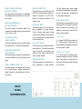
The Mclntosh Ml 3 is five laboratory instruments combined into one
compact instrument. It is a professional oscilloscope, relative signal
strength indicator, calibrated FM deviation meter, calibrated balance
meter, and phase indicator. These instruments are used by FM stations
to determine the best possible performance for your listening enjoyment.
2. Distortion is often heard in the program signal.
3. Stereo separation may be reduced.
4. The stereo effect may be completely lost.
CONTENTS
MI3
5. Stereo indicators may fail to function, or function erratically.
GENERAL DESCRIPTION
TECHNICAL DESCRIPTION
SPECIFICATIONS
FRONT PANEL INFORMATION
BACK PANEL INFORMATION
CABINET INSTALLATIONS
CONNECTIONS
SET UP PROCEDURES
SYSTEM HOOK UP
TYPICAL PATTERNS
GUARANTEE
1
2
3
4
5
6
7, 8
9
10
11
12
To overcome multipath reception it is usually necessary to turn the
antenna to receive the FM signal by one predominant path. Rotating a
directional antenna is effective at correcting multipath reception. In a
metropolitan area where a simple antenna such as a dipole is used
repositioning the antenna will achieve the same result.
The Ml 3 is a very effective tuning indicator:
1. Signal strength is shown by the vertical position of the display
trace. The higher the position of the trace the greater the signal
strength.
1
2. Correct tuning occurs when the display trace is centered horizontally on the screen. Since the display trace effectively follows
the tuner I.F. response curve, centering the trace tunes the detector to the center of the I.F. curve.
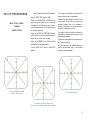
The Ml 3 Maximum Performance Indicator is a versatile instrument.
When used with either a stereo preamplifier, or power amplifier the
Ml 3 when switched to the L+R AUDIO position will show you the
character of the audio signals present. The Ml 3 will:
1. Display a trace along the L+R line when a monaural program
is playing.
2. Will display along the L —R line when a monaural program
source has one channel out of phase.
3. Display a vertical trace if only the left channel is being delivered.
4. Display a horizontal trace when only the right channel is being
delivered.
5. Helps you set the precise balance of your system. With the balance control you can change the angle of the L+R or L — R display.
6. A stereo program will be a complex and varying circular or
elliptical display of irregular outline that depends on channel
separation or on the phase amplitude relation of the left and
right channel.
TECHNICAL
DESCRIPTION
The Ml 3 Maximum Performance Indicator is essentially an oscilloscope
using a three inch cathode-ray tube. Adequate brightness is assured
with a 1350 volt accelerating voltage. A sharper well defined trace is
provided by using separate focus and astigmatism controls.
Two identical direct coupled push-pull amplifiers are used in the horizontal and vertical deflection circuits. Phase shift in each amplifier Is
held to within a few degrees from D.C. throughout the operating
frequency range. Phase differences between vertical and horizontal
amplifiers are held to within a few degrees.
The high voltage power supply uses a selenium rectifier. The low voltage supplies use selenium rectifiers, two gas filled rectangular tubes
and an electronic voltage regulator. The operating voltages from
these supplies are carefully regulated over a wide range of power
line variations. This design feature assures a steady indicator trace
despite changing line voltage.
For multipath display the horizontal deflection voltage is obtained
from the tuner discriminator output ahead of the de-emphasis network.
This voltage is proportional to the frequency deviation of the FM
transmission. The maximum width of the indicator screen is designed to
correspond to approximately plus and minus 75 kilocycle deviation of
the FM transmitter.
The horizontal multipath input is connected through the deviation input
jack and the deviation (horizontal) calibration control.
For multipath display the vertical deflection voltage is obtained from
the tuner Automatic Gain Control circuit at the input to the first limiter.
This voltage is proportional to the FM stations instantaneous signal
strength. However, the average proportionally is expotential. Because
of the expotential characteristic, a weak station will produce adequate
vertical deflection. A powerful local station should position the center
of the indicator trace about half to three quarters of an inch below the
top of the vertical scale. The vertical Multipath Input is connected
through the Signal Strength Input and the Signal Strength (vertical)
Calibration Input Control.
For L+R audio display the horizontal deflection voltage is obtained
from the right channel output of a tuner, a preamplifier or even a
power amplifier. The deflection voltage is connected through the
Right Audio Input and the Right Gain Control. For L + R audio display
the vertical deflection voltage is obtained from the left channel output
of a tuner, a preamplifier, or a power amplifier. The deflection voltage
is connected through the Left Audio Input and the Left Gain Control.
With a normal loudness monaural signal both audio input controls are
adjusted for equal deflection of the display trace. (At this point the
trace will be on the L + R line if the two signals are in phase or the
L - R line if they are 1 80° out of phase.)
MI3
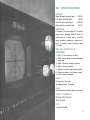
SPECIFICATIONS
SENSITIVITY
Signal Strength (vertical) Input
Left Audio (vertical) Input
Deviation (horizontal) Input
Right Audio (horizontal) Input
— 700 MV
20 MV
±350 MV
20 MV
DIMENSIONS
Front panel: 16 inches wide by 5-7/16 inches
high; chassis (including PANLOC shelf) 15
inches wide by 5 inches high by 13 inches
deep, including connectors; clearance in
front of mounting panel including knobs,
1 ½ inches.
TUBE AND SEMICONDUCTOR
COMPLEMENT
1—3RP1, 3 inch cathode ray tube.
4—6EA8, horizontal and vertical deflection
amplifiers.
1—6EA8, electronic voltage regulator.
2—OB2, voltage regulators.
1—Selenium rectifier, high voltage rectifier.
6—Selenium rectifiers, low-voltage supply.
4—silicon planar transistors.
WEIGHT
Chassis only, 23 pounds.
In shipping carton, 30 pounds.
FINISH
Anodized gold and black glass front panel
POWER CONSUMPTION
50 watts, 105 to125 volts.
50 to 60 cycles.
FUSE
1 Ampere Slo-Blo
3
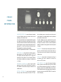
FRONT
PANEL
INFORMATION
INDICATOR SCREEN—The screen is the face of a cathode
ray tube. Calibration marks are provided to allow correct
positioning of the indicator trace.
tion the indicator trace can be easily moved to the correct
vertical position. For multipath display the trace is positioned
at the bottom reference point.
A correctly tuned station free of multipath distortion appears
as a smooth curve centered on the indicator screen vertical
scale. The vertical line is marked to show the relative strength
of the FM signal. A strong local signal should position the display about ½ to ¾ inch from the top of the vertical scale.
The horizontal line is marked to show deviation.
For audio indications the trace is positioned at the center
reference point. This shift in position occurs automatically as
the Scope Test control is turned. An internal adjustment
labeled L+R position is factory preset but can be readjusted
if needed.
The two 45° sloped lines show L+R and L — R audio information.
INTENSITY —This control adjusts the brightness of the indicator trace. After the Intensity control has been tuned, the
Focus control may have to be adjusted for the best possible
indicator trace.
SCOPE TEST—This control switches the indicator circuits to
show multipath, Left and Right audio signals or TEST. The
TEST position switches the indicator trace to a single dot for
adjustment of trace position, focus and intensity. Different
trace reference positions are necessary for multipath and
L + R Audio.
HORIZONTAL POSITION—This control moves the indicator trace to the left or right. With the Scope Test switch in
TEST position, the trace dot tan easily be centered on the
indicator screen.
VERTICAL POSITION—This control moves the indicator
trace up or down. With the Scope Test switch in TEST posi-
4
FOCUS—This control adjusts the sharpness and clarity of
the indicator trace. Focus is easiest with the Scope Test
switch in the TEST position.
AUDIO DISPLAY—This control will increase the display
area on the face of the cathode ray tube. At low volumes
you will Find the display would be small. To see all the information present turn the AUDIO DISPLAY toward max.
This will increase the size of the display. At high volumes you
may want to turn down the AUDIO DISPLAY to reduce the
size of the display.
SIGNAL STRENGTH (VERTICAL)
MULTIPATH CONTROL
This control adjusts the position of the Multipath
trace display along the vertical scale of the indicator screen.
DEVIATION (HORIZONTAL)
MULTIPATH CONTROL
This control adjusts the maximum width of the
multipath trace display along the horizontal scale
of the indicator screen.
LEFT GAIN (VERTICAL)
AUDIO CONTROL
This control adjusts the maximum vertical indicator
trace deflection for a left channel audio signal.
RIGHT GAIN (HORIZONTAL)
AUDIO CONTROL
This control adjusts the maximum horizontal indicator trace deflection from a right channel audio
signal.
SIGNAL STRENGTH INPUT (TP1)
This input connects to a Mclntosh tuner Test Point
No. 1, which supplies a voltage proportional to
Signal Strength for vertical deflection of the indicator trace.
DEVIATION INPUT (TP2)
This input connects to a Mclntosh tuner Test
Point No. 2, which supplies a voltage proportional to deviation of the FM transmission for horizontal deflection of the
indicator trace.
LEFT AUDIO INPUT
This input connects to the left output of a
tuner, preamplifier, or power amplifier.
The left channel audio signal voltage
causes vertical deflection of the indicator
trace. This input jack is in parallel with the
left audio output jack.
LEFT AUDIO OUTPUT
This output jack is in parallel with the left
audio input jack. This parallel connection
makes it convenient for connecting a preamplifier or tuner output to both the Ml 3
and the power amplifier.
RIGHT AUDIO INPUT
This input connects to the right output of a
tuner, preamplifier, or power amplifier.
The right channel audio signal voltage
causes a horizontal deflection of the indicator trace. This input jack is in parallel with
the right audio output jacks.
RIGHT AUDIO OUTPUT
This output jack is in parallel with the right
audio input jack. This parallel connection
makes it convenient for connecting a preamplifier or tuner output to both the Ml 3
and the power amplifier.
1A SLO BLO
A 1 ampere SLO-BLO fuse protects the
Ml 3 indicator circuits. This fuse does not
protect additional equipment connected to
the back panel AC outlets.
350 WATTS AC OUTLET
A 117 volt AC outlet is provided for extra
equipment drawing as much as 350 watts
power. The outlet is not fused and is on
whenever the Ml 3 power cord is connected
to an AC outlet.
BACK
PANEL
INFORMATION
5
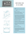
HOW TO INSTALL YOUR
Ml 3 IN A CABINET
1 Use the mounting template to position where you will mount the
instrument.
NOTE: The template lets you position the cutout from the front of
the panel.
2 Mark the "A" and "B" drill holes.
3 Mark the four corners. Join the four corners to make a rectangle.
Use the edge of the template as a straight edge.
4 Drill the mounting holes and cut out the rectangular hole.
5 Fasten the two mounting strips to the panel. Use two of the fillisterhead screws provided. There are 12 fillister-head screws in the
package. Six are % inches long and six are 1 % inches long. For
panels under ½ inch thick use the ¾ inch screws. For panels over
½ inch thick use the 1¼ inch screws. Insert a screw in the center
hole. ("B" hole on the template.) Tighten the screws so the heads
are pulled half of their thickness into the wood.
6 Fasten the shelves to the mounting brackets. Use two fillister-head
screws in the "A" holes for each shelf.
7 Place the template over the mounting screws. The screws should
be centered in the "A" and "B" holes on the template. The PANLOC shelves should match the vertical dash lines on the template.
8 Remove the plastic protective covering from the instrument. Turn
the instrument over. To prevent damage rest the instrument on
the shipping pallet.
9 Remove the four (4) plastic feet.
10 Now the instrument is ready for installation.
11 Put the power cord through the opening. Slide the unit into the
brackets. Carefully slide the Ml 3 into the opening so the plastic
rails on the bottom of the chassis engage the grooves in the metal
mounting brackets. Slide the Ml 3 in until its front panel is against
the cabinet mounting panel.
12 Secure the instrument to the mounting bracket by pushing "in" the
Panloc Buttons.
6
cable to the tuner chassis ground. Use one of the 1 foot long low-loss
shielded cables, stripped and tinned on one end (female jacks on the
other end) supplied with the Ml 3.
TWO PAIRS OF 3 FOOT LONG LOW LOSS SHIELDED CABLES ARE
SUPPLIED WITH THE Ml 3. USE THESE CABLES TO CONNECT THE
Use a connector with male plugs to connect the soldered - in cable from
the tuner to the Deviation (horizontal) Input on the Ml 3. Connect a 3 foot
low-loss shielded cable from the test point (on top of tuner chassis) to the
Signal Strength (vertical) Input on the Ml 3.
Ml 3 TO A TUNER FOR MULTIPATH RECEPTION. A PAIR OF 6
FOOT LONG SHIELDED CABLES ARE SUPPLIED FOR CONNECTING
CONNECTING TO MclNTOSH MR 65B TUNER.
THE Ml 3 IN AUDIO CIRCUITS.
Remove capacitor C 27 (.005 MFD) connected between TP No. 1 and
chassis ground. MR 65B tuners, serial numbers 300UO and above, do not
have this capacitor.
CONNECTING TO MclNTOSH MR 71 OR MR 67 TUNER.
Connect a 3 foot low loss shielded cable from the TP No. 1 (Test Point
No. 1 jack on top of the tuner chassis) to the Signal Strength (vertical)
Input on the Ml 3.
Connect a second 3 foot low loss shielded cable from the TP No. 2
(Test Point No. 2 jack on rear of the tuner chassis) to the deviation
(horizontal) Input on the Ml 3.
CONNECTING
TO
MclNTOSH
MX
110
TUNER-PREAMPLIFIER
WITH Z OR X SERIAL NUMBERS
Connect a 3 foot low loss shielded cable from the MX 1 1 0 TP No. 1
(Test Point No. 1 jack on top of the tuner chassis) to the Signal Strength
(vertical) Input on the Ml 3.
Connect a second 3 foot low-loss shielded cable from the MX 110 TP
No. 2 (Test Point No. 2 jack on top of the tuner chassis) to the Deviation
(horizontal) Input on the Ml 3.
Connect a 3 foot low-loss shielded cable from the MR 65B TP No. 1 (Test
Point No. 1 on tuner back panel) to the Signal Strength (vertical) Input
on the Ml 3.
Connect a 3 foot long low-loss shielded cable from the MR65B TP No. 2
(Test Point No. 2 on rear of tuner chassis) to the Deviation (horizontal)
Input on the Ml 3.
CONNECTING TO MclNTOSH MR 65 AND 65A
Remove capacitor C 31 (.005 MFD) connected between the test point
and ground.
Connect a 3 foot low-loss shielded cable from the MR 65A Test Point
(jack on top of tuner chassis) to the Signal Strength (vertical) Input on
the Ml 3.
Connect a 3 foot low-loss shielded cable from the MR 65A MPX out jack
on the tuner back panel to the Deviation (horizontal) Input on the Ml 3.
WITH M SERIAL NUMBERS
If an external multiplex adapter is being used with the MR 65 a "Y"
connector will be needed in the MPX output jack. This allows both the
MPX adapter and the lead to the Ml 3 to be connected.
Remove capacitor C 1 30 (.005 MF) connected between the test point
and ground.
CONNECTING TO MclNTOSH MR 66 TUNER
Solder the center lead of a 1 foot low-loss shielded cable to the junction
point of R 139 ( 1 0 K ) and C 125 (.1 MFD). Solder the outer shield of the
Remove capacitor C 1 25 (.005 MFD) connected between the test point
and ground.
CONNECTING
TO
MclNTOSH
MX
110
TUNER-PREAMPLIFIER
7
Connect a 3 foot low-loss shielded cable from the TEST POINT (on top
of tuner chassis) to the Signal Strength (vertical) Input on the Ml 3.
Connect a 3 foot low-loss shielded cable from the FM multiplex output
jack on the tuner back panel to the Deviation (horizontal) Input on the
Ml 3.
Connect a low-loss shielded cable from the discriminator output (ahead
of the de-emphasis network) to the Deviation (horizontal) Input on the
Ml 3.
Adjust the SIGNAL STRENGTH (vertical) Multipath control on the back
panel until the pattern on the indicator screen is about ¾ inch from the
top of the vertical scale.
CONNECTING TO MclNTOSH MR 55A TUNER
Remove the feed-through capacitor L 43 (1000 MMF) connected to
TP No. 1. This capacitor can best be removed by unsoldering. Solder the
center lead of a 1 foot low-loss shielded cable to the Test Point end of
R 27 (100K resistor). Solder the outer shield of the cable to the chassis
where the feed through capacitor was soldered. The cable can feed
through the hole In the chassis where the capacitor was soldered. Use one
of the 1 foot long low-loss shielded cables, stripped and tinned on one
end (female jacks on the other end) supplied with the Mi 3.
DEVIATION MULTIPATH CONTROL
Tune in a relatively strong local signal with the antenna positioned for
maximum multipath.
Adjust the DEVIATION (horizontal) Multipath control until the horizontal
pattern (loudest signal from the station) does not extend over the ends of
the horizontal scale of the indicator screen.
Use a connector with male plugs to connect the soldered - in cable to the
signal strength (vertical) Input on the Ml 3. Connect a 3 foot low-loss
shielded cable from the multi-out (multiplex output) jack on the tuner to
the Deviation (horizontal) Input.
Turn the Ml 3 Power switch to ON.
If a multiplex adapter is being used with the MR 55A, a "Y" connector
will be needed in the MULTI-OUT jack. This allows both the multiplex
adapter and the lead to the Ml 3 to be connected.
Adjust the HORIZONTAL POSITION front panel control until the trace is
centered horizontally on the Indicator screen. Calibration lines are provided on the Indicator face for centering purposes.
CONNECTING TO MclNTOSH MR 55 TUNER
Solder a wire across resistor R 62
the tuner chassis.
meg) connected to the test point on
Connect a 3 foot low-loss shielded cable from the test point on top of the
tuner chassis to the Signal Strength (vertical) Input on the Ml 3.
Connect a 3 foot low-loss shielded cable from the MULTIPLEX OUTPUT
jack on the tuner to the Deviation (horizontal) Input on the Ml 3.
L+R AUDIO INDICATIONS
Turn the SCOPE TEST switch to TEST.
Adjust the vertical position control until the trace dot is positioned at the
bottom of the center vertical scale.
Adjust the INTENSITY AND FOCUS controls for a sharp and clear trace
dot.
Turn the SCOPE TEST switch to L + R Audio.
Set the preamplifier or power amplifier to MONO.
Adjust the LEFT GAIN and RIGHT GAIN controls on the Ml 3 until the
incoming program causes the Indicator trace to align directly over the
line.
CONNECTING TO ALL OTHER TUNERS
Connect a low-loss shielded cable from the input to the first FM limiter
through a 100K resistor, to the Signal Strength (vertical) Input on the Ml 3.
8
NOW YOUR Ml 3 IS READY TO HELP YOU ACHIEVE MAXIMUM
PERFORMANCE FROM YOUR SYSTEM
SET UP PROCEDURES
the Ml 3 power switch to the ON position.
Turn the SCOPE TEST switch to TEST.
MULTIPATH AND
TUNING
INDICATION
Adjust the HORIZONTAL POSITION front
panel control until the trace dot is centered
horizontally on the indicator screen. Calibration lines are provided on the indicator face
for centering purposes.
Adjust the VERTICAL POSITION front panel
control until the trace dot is positioned at the
bottom center of the vertical scale.
Adjust the INTENSITY and FOCUS controls
for a sharp aTurnnd clear trace dot.
Turn the SCOPE TEST switch to MULTIPATH
position.
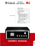
1. Trace Dot Positioned at Bottom
Center of Vertical Scale.
Turn the tuner tuning dial to the desired FM
station, either stereo or monophonic.
Observe the trace pattern on the Ml 3 indicator screen. If the pattern is uniform and
relatively smooth, little or no multipath is
present. If the pattern is irregular with vertical traces, multipath is present.
The height of the trace above the base line
indicates the relative signal strength of the
station being received.
Rotate the tuner antenna, while watching the
Ml 3 Indicator screen.
Stop the antenna in the position where the
trace is the smoothest curve. In this positron
there is the least multipath.
3. Trace Showing Multipath.
2. Uniform and Relatively Smooth Trace
with Little or No Multipath Present (80% Modulation).
9
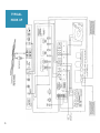
TYPICAL
HOOK UP
10
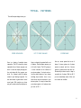
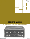
TYPICAL
PATTERNS
The oscilloscope display shows you:
STEREO SEPARATION
Here is a display of excellent stereo
separation. The Ml 3 shows the stereo
separation from all stereo program material. You see the display change position and shape with the program material. You interpret what the display
means to your listening enjoyment. You
see what makes a good stereo record
sound good. With practice you know
why your records sound the way they do.
LEFT TO RIGHT BALANCE
Here is a display of a system that it is out
of balance. Precise balance assures you
a full wall of sound. The Ml 3 gives you
a visual indication of the balance of
your stereo system. You check and correct the output balance of your stereo
cartridge, tape recorder, tuner, or any
other stereo source connected to your
stereo system. It is easy to know when
your stereo system is In balance when
you use an Ml 3.
SYSTEM PHASE
Here is a stereo system that is out of
phase. A stereo system out of phase
sounds un-natural and thin. A stereo
system in phase sounds alive and rich.
Occasionally a stereo record or tape is
recorded out of phase. With the Ml 3
you are immediately aware of this and
can correct the condition.
11
Your Ml 3 will give you many years of pleasant and satisfactory
performance. If you have any questions concerning the operation or maintenance of this indicator please contact:
Customer Service
Mclntosh Laboratory Inc.
2 Chambers Street
Binghamton, New York 13903
Our telephone number is 723-5491.
The direct dial area code is 607.
GUARANTEE
Mclntosh Laboratory Incorporated guarantees this
equipment to perform as advertised. We also guarantee the mechanical and electrical workmanship
and components of this equipment to be free of
defects for a period of 90 days from
purchase. This guarantee does not extend
ponents damaged by improper use nor
extend to transportation to and from the
date of
to comdoes it
factory.
3-YEAR FACTORY SERVICE CONTRACT
An application for a FREE 3-YEAR FACTORY SERVICE CONTRACT is included in the pocket in the back
cover of this manual. The FREE 3-YEAR FACTORY
SERVICE CONTRACT will be issued by Mclntosh
Laboratory upon receipt of the completely filled out
application form. If the application is not mailed to
Mclntosh Laboratory, only the services offered under
the standard 90-day guarantee will apply on this
equipment. TAKE ADVANTAGE OF 3 YEARS OF
FREE FACTORY SERVICE BY FILLING IN THE APPLICATION NOW.
12
Design subject to change without notice.
MclNTOSH LABORATORY INC.
2 CHAMBERS ST., BINGHAMTON, N. Y. 13903
607-723-3512
Design sub|ecl to change without notice.
Printed In U.S.A.
Be102002