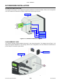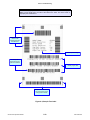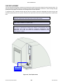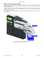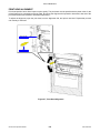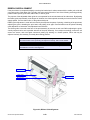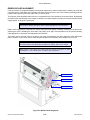
1
GL408/412e
PRINTER
OPERATOR MANUAL
PN: 9001163A
SATO America, Inc.
10350A Nations Ford Road
Charlotte, NC 28273
Main Phone: (704) 644.1650
Technical Support Hotline: (704) 644.1660
Technical Support Fax: (704) 644.1661
E-Mail: [email protected]
[email protected]
www.satoamerica.com
WARNING
THE EQUIPMENT REFERENCED IN THIS DOCUMENT COMPLIES WITH THE REQUIREMENTS IN PART 15
OF FCC RULES FOR A CLASS B COMPUTING DEVICE. OPERATION OF THIS EQUIPMENT IN A
RESIDENTIAL AREA MAY CAUSE UNACCEPTABLE INTERFERENCE TO RADIO AND TV RECEPTION.
PN: 9001163A
TABLE OF CONTENTS
INTRODUCTION
About This Manual
General Description
Control Features
1-2
1-3
1-4
TECHNICAL DATA
Physical Characteristics
Enviromental
Power
Processing
Command
Interface Modules
Print
Sensing
Media
Ribbon
Regulatory
Character Font Capabilities
Barcode Capabilities
2-2
2-2
2-2
2-2
2-2
2-2
2-2
2-3
2-3
2-3
2-3
2-4
2-5
INSTALLATION
Unpacking & Parts Identification
Printer Installation
Site Location
Cable Connection
Media Selection
Media & Ribbon Loading
Operational Mode Selection
Continuous Mode
Tear-Off Mode
Cutter Mode
Dispense Mode
Linerless Mode
Interface Selection
RS232C High-Speed Serial Interface
IEEE1284 Parallel Interface
Universal Serial BUS (USB) Adapter
Local Area Network (LAN) Ethernet
802.11G Wireless
All Interfaces
Accessories Installation
Interface Installation
Flash Memory Card
GL408-412e Operator Manual
3-2
3-3
3-3
3-3
3-4
3-4
3-6
3-6
3-6
3-6
3-6
3-6
3-8
3-8
3-10
3-11
3-11
3-12
3-14
3-22
3-22
3-22
PN: 9001163A
PRINTER CONFIGURATION
Printer Configuration
Configuration Modes
User Mode
Configuration Mode
Advanced Mode
Serial Interface Mode
Parallel Interface Mode
Centronics Interface Mode
Universal Serial BUS (USB) Interface Mode
Local Area Network (LAN) Interface Mode
Wirerless Local Area Network (WLAN) Interface Mode
PGL Emulation Mode
ZGL Emulation Mode
DGL Emulation Mode
TGL Emulation Mode
IGL Emulation Mode
Diagnostics Mode
Printer Management Mode
Misc Quick Menus
Display Intensity Adjustment
Buffer Clear
Soft Reset
Key Lock/Unlock
Menu Definition Tables
User Mode
Configuration Mode
Advanced Mode
Serial Interface Mode
Parallel Interface Mode
Centronics Interface Mode
Universal Serial BUS (USB) Interface Mode
Local Area Network (LAN) Interface Mode
Wirerless Local Area Network (WLAN) Interface Mode
PGL Emulation Mode
ZGL Emulation Mode
DGL Emulation Mode
TGL Emulation Mode
IGL Emulation Mode
Diagnostics Mode
Printer Management Mode
Misc Quick Menus
Display Intensity Adjustment
Buffer Clear
Soft Reset
Key Lock/Unlock
GL408-412e Operator Manual
4-2
4-3
4-3
4-4
4-5
4-7
4-8
4-9
4-10
4-11
4-12
4-13
4-14
4-15
4-16
4-17
4-18
4-19
4-20
4-20
4-20
4-21
4-21
4-22
4-22
4-26
4-29
4-39
4-44
4-47
4-50
4-52
4-56
4-63
4-69
4-72
4-75
4-78
4-82
4-85
4-88
4-88
4-88
4-88
4-88
PN: 9001163A
TROUBLESHOOTING
Error Signal Troubleshooting
Troubleshooting Table
Interface Troubleshooting
Parallel Interface
RS232 Serial Interface
Universal Serial Bus (USB) Interface
LAN Ethernet Interface
802.11G Wireless Interface
Centronics Interface
Test Print Troubleshooting
Hex Dump Mode
Test Label Printing
Sample Test Label
5-2
5-8
5-10
5-10
5-10
5-10
5-11
5-11
5-11
5-12
5-12
5-12
5-13
MAINTENANCE
Cleaning Procedures
Replacement Procedures
Print Head
Fuse
Media Platen Roller
Adjustment Procedures
Label Sensor Positioning
Print Head Balance
Print Head Pressure
Print Head Alignment
Ribbon Guide
Ribbon Roller Alignment
GL408-412e Operator Manual
6-2
6-3
6-3
6-4
6-5
6-6
6-6
6-7
6-8
6-9
6-10
6-11
PN: 9001163A
INTRODUCTION
•
•
•
GL408-412e Operator Manual
About This Manual
General Description
Control Features
1-1
PN: 9001163A
Unit 1: Introduction
ABOUT THIS MANUAL
This manual is laid out consistent with the product discussed and provides all of the information required for printer
installation, configuration, operation, and light maintenance. Refer to this product’s Programming Reference
document for instructions on printer programming through a host system.
This manual also incorporates the use of special information boxes. Examples of these boxes and the type of
information provided in each, are below.
WARNING: PROVIDES INFORMATION THAT, IF UNHEEDED, MAY RESULT IN
PERSONAL INJURY.
CAUTION: PROVIDES INFORMATION THAT, IF UNHEEDED, MAY RESULT IN
EQUIPMENT DAMAGE.
ATTENTION: Provides information that is deemed of special importance but will not
result in personal injury or product damage if unheeded.
NOTE: Provides helpful hints to assist in performing the tasks at hand.
LCD DISPLAY: Provides the specific display that should be visible on the LCD at that
point.
A comprehensive Table Of Contents provided at the front of this manual facilitates rapid movement within. The
contents identify the different Units, Chapters, and some Sections. Each references the page number of their
commencement.
The pages of this manual have embedded headers and footers to assist the user in identifying his or her exact
position within the manual. The header provides the unit number followed by its name. The footer identifies the
product on the left, the page number in the center, and the manual’s part number to the right side of the page.
Page enumeration is two-part with each separated by a hyphen. The first character set references the Unit and the
second identifies the page number within that unit. Page numbers begin with the numeral one (1) at the beginning
of a new unit and ascend sequentially.
GL408-412e Operator Manual
1-2
PN: 9001163A
Unit 1: Introduction
GENERAL DESCRIPTION
The GL4e Series printers are specifically designed for use in high-volume, labeling applications demanding great
reliability and around the clock operation. It’s aluminum chassis provides the needed corrosion resistance
demanded by some industrial applications. The coated interior frame provides strength and stability.
The stylish front housing cover and operator panel are both molded of extra-durable, black ABS plastic to not only
provide protection against corrosive chemicals; but to also provide a low-show, easy clean surface for unsightly
grim.
This printer model has the attractiveness desired for commercial applications coupled with the muscle expected of
an industrial printer.
Right Housing Cover
Expanded Memory Cover
Left Housing Cover
Ribbon Supply Spindle
Ribbon Rewind Spindle
Media Holder
Media Guide
Ribbon Platen Roller
Ribbon Guide
Label Sensor
Rear Housing Cover
Media Platen Roller
Print Head Latch
Front Housing Cover
Upper Print Assy
Media Damper
Lower Print Assy
Figure 1-1, Primary Components
GL408-412e Operator Manual
1-3
PN: 9001163A
Unit 1: Introduction
CONTROL FEATURES
This chapter identifies the interactive control features of the printer. These functions are defined generally here.
More specific explanations will be found throughout this manual on how to use them.
LCD Display
Communicates operational conditions via the use
of icons and text.
LED Indicators
POWER
Illuminates when the power on.
ONLINE
Illuminates when communication is available.
Flashes when fails.
STATUS
Flashes when an error occurs. Flashes when
sending/receiving data.
POWER ON LINE
STATUS
LABEL
RIBBON
LABEL
Flashes when paper error occurs.
RIBBON
Flashes when ribbon error occurs.
Operator Buttons
FUNCTION
ENTER
CANCEL
FEED
Feeds the equivalent of a sheet of paper when
pressed once. Positions paper if misaligned.
LINE
Starts and stops printing and transmission of
data.
Maintenance Panel
FUNCTION
Allows movement through the various menus
and modes.
Permits the movement of the cursor for input.
ENTER
Allows the selection of an option.
CANCEL
Cancels a print job. Allows return to the previous
screen when moving through the menus.
Power Switch
Breaks the circuit providing power to the printer.
Figure 1-2, Operator Panel
GL408-412e Operator Manual
1-4
PN: 9001163A
TECHNICAL DATA
•
•
•
•
•
•
•
•
•
•
•
•
•
GL408-412e Operator Manual
Physical Characteristics
Environmental
Power
Processing
Command
Interface Modules
Print
Sensing
Media
Ribbon
Regulatory Approvals
Character Font Capabilities
Barcode Capabilities
2-1
PN: 9001163A
Unit 2: Technical Data
PHYSICAL CHARACTERISTICS
Width
10.75 Inches (271 mm)
Height
12.00 Inches (305 mm)
Depth
18.00 Inches (455 mm)
Weight
33 Pounds (15 Kg)
ENVIRONMENTAL
Operating Temperature
41 to 104°F (5° to 40°C)
Storage Temperature
-4 to 140°F (-20° to 60°C)
Storage Humidity
15 to 85% RH Non-Condensing
Operating Humidity
15 to 85% RH Non-Condensing
POWER
Input Voltage
Consumption Voltage
100-120/200-240 Volts AC +/- 10%, 50/60 Hertz +/-5%
Maximum: 222 Volts AC, 219 Watts (when print ratio is 50%)
Standby: 22.3 Volts AC, 20.6 Watts
PROCESSING
CPU
32 Bit RISC
Flash ROM
8 Megabytes
Receive Buffer
2.95 Megabytes maximum, 0.95 Megabytes near full
COMMAND
Standard
SATO Barcode Printer Language (SBPL)
Intelligent Command
Non-Standard
N/A
INTERFACE MODULES
Enhanced Parallel Port
IEEE1284 (EPC compatible)
Serial Port
9-Pin RS232C
Universal Serial Bus (USB)
USB Adapter (480 Mbps)
Local Area Network (LAN)
10BASE-T/100BASE-TX Automatic Switching
Ethernet (Wireless LAN)
802.11g Wireless Wi-Fi
PRINT
Method
Maximum Speed (selectable)
Direct Thermal / Thermal Transfer
2, 3, 4, 5, 6, 7, 8, 9, 10 Inches Per Second (50.8 - 254 mm)
Print Module (dot size)
Resolution
.0049 Inches (.125 mm)
GL408e: 203 Dots Per Inch (8 dpmm)
GL412e: 305 Dots Per Inch (12 dpmm)
Maximum Print Width
4.09 Inches (104 mm)
Maximum Print Length
98.98 Inches (2514 mm)
GL408-412e Operator Manual
2-2
PN: 9001163A
Unit 2: Technical Data
SENSING
Gap
Position & Sensitivity Adjustable
Reflective Eye-Mark
Position & Sensitivity Adjustable
Ribbon Near End
Fixed (enabled/disabled)
Media Out
Fixed (always enabled)
Ribbon Out
Fixed (always enabled)
Cover Open
Fixed (always enabled)
MEDIA
Width
Media Width: 0.87 to 5.04 Inches (22 - 128mm)
Media Width with Backing Paper: 0.98 to 5.16 Inches (25 - 131mm)
Length (Continous)
Media Length: 0.24 to 15.63 Inches (6 - 397mm)
Media Length with Backing Paper: 0.35 to 15.75 Inches (9 - 400mm)
Length (Tear-Off)
Media Length: 0.67 to 15.63 Inches (17 - 397mm)
Media Length with Backing Paper: 0.79 to 15.75 Inches (20 - 400mm)
Type
Thickness
Roll or Fan-Fold
Eye-Mark or Gap
Direct Thermal or Thermal Transfer
0.002 to 0.010 Inches ( 0.06 - 0.268 mm)
Roll Diameter
Maximum: 10.43 Inches (265mm)
Core Diameter
1.5 to 4.0 Inches (38.1 - 101.6mm)
Wind Direction
Face In, Face Out (linerless only)
Fan-Fold Height
Maximum: 7.87 Inches (200mm)
RIBBON
Width
Maximum: 5.04 Inches (128mm)
Length
1476 Feet (450M)
Wound
Face In, Face Out
Core Diameter
1.00 Inch (25.6 mm)
Roll Diameter
Maximum: 3.35 Inches (85 mm)
REGULATORY
Radiation Noise
FCC Part 15, Subpart B, Class B
EN55022 Class B
Static Electricity
IEC61000-4-2, Level 3
AC Line Noise
Above: 1000Vp-p
Packing Drop Standard
ISTA-2A
Environmental (RoHS)
Chromium: below 0.1%
Lead: below 0.1%
Mercury: below 0.1%
Cadmium: below 0.01%
Polybrominated Bipheny (PBB): below 0.1%
Polybrominated Diphenyl Ether (PBDE): below 0.1%
GL408-412e Operator Manual
2-3
PN: 9001163A
Unit 2: Technical Data
CHARACTER FONT CAPABILITIES
MATRIX FONTS
XU
5 dots W x 9 dots H (Helvetica)
XS
17 dots W x 17 dots H (Univers Condensed Bold)
XM
24 dots W x 24 dots H (Univers Condensed Bold)
OA Font (OCR-A)
GL408e: 15 dots W x 22 dots H
GL412e: 22 dots W x 33 dots H
OB Font (OCR-B)
GL408e: 20 dots W x 24 dots H
GL412e: 30 dots W x 36 dots H
AUTO SMOOTHING FONTS
XB
48 dots W x 48 dots H (Univers Condensed Bold)
XL
48 dots W x 48 dots H (Sans Serif)
VECTOR FONT
Proportional or Fixed Spacing
Font Size 50 x 50 dots to 999 x 999 dots
Helvetica, 10 Font Variations
AGFA RASTER FONTS
A Font
CG Times, 8 to 72 pt.
B Font
CG Triumvirate, 8 to 72 pt.
DOWNLOADABLE FONTS
N/A
CHARACTER CONTROL
Expansion up to 12 x in either the X or Y coordinates.
Character Pitch Control
Line Space Control
Journal Print Facility
0, 90, 180, and 270 Degree Rotation
GL408-412e Operator Manual
2-4
PN: 9001163A
Unit 2: Technical Data
BARCODE CAPABILTIES
Linear Bar Codes
UPC A/E
JAN 8/13
EAN 8/13
Code 39
Code 93
Code 128
Interleaved 2 of 5
Industrial 2 of 5
Matrix 2 of 5
Bookland
NW-7
MSI
RSS-14
POSTNET
UCC/EAN 128
Customer Barcode
Two Dimemsional
QR Code
Data Matrix
Maxi Code
PDF417
Micor PDF417
Synthetic Symbol
Ratios
Bar Height
1:2, 1:3, 2:5, User definable bar widths
4 to 999 dots, User progammable
Rotation
Sequential Numbering
Expansion Ratio of Character
Graphics
Form Overlay
GL408-412e Operator Manual
0, 90, 180, and 270 Degrees
Sequential numbering of both numerics and bar codes
Height: 1 to 12 times, Width: 1 to 12 times
Full dot addressable graphics, SATO Hex/Binary, BMP or PCX formats
Form overlay for high-speed editing of complex formats
2-5
PN: 9001163A
INSTALLATION
•
•
•
•
•
GL408-412e Operator Manual
Unpacking & Parts Identification
Printer Installation
Operational Mode Selection
Interface Selection
Accessories Installation
3-1
PN: 9001163A
Unit 3: Installation
UNPACKING & PARTS IDENTIFICATION
Unpack the printer as directed in the following procedure.
1
Place the shipping container (box) upright on a soid, flat surface.
2
Open the box, remove any loose items and the first layer of packing material.
3
Carefully lift the printer and accessories from the box and place them on a solid flat surface.
4
Remove the plastic covers from the packed items and visually inspect for physical damage.
5
Ensure all components are present as dictated on the Packing List.
6
Report damaged property.
Accessory Box
Printer
Cushion
Shipping Container
Figure 3-1, Unpacking & Parts Identification
GL408-412e Operator Manual
3-2
PN: 9001163A
Unit 3: Installation
PRINTER INSTALLATION
This chapter provides guidance on how to station, connect, and load the printer once unpacked. Following printer
setup, procede to the next chapter for information on interface selection.
SITE LOCATION
•
Stationed on a solid flat surface.
•
Stationed away from hazardous materials.
•
Stationed within operational distance of the host based on interface specifications.
CABLE CONNECTION
The diagram below (Figure 3-2) displays the printer’s connectors and ports for power supply and host interfacing.
For interfacing, choose the desired method and connect it’s respective cable as indicated.
All interface boards are integrated except the LAN/WLAN board. This will have to be installed as shown.
When the interface cable is connected, or the board is installed, the interface option will display in the configuration
menus of the operator panel. Refer to the Configuration unit of this manual to configure the printer for host
computer interfacing.
NOTE: Multiple interface options may display in the printer’s LCD menus, the
desired option must be chosen.
Host Computer
Printer
Interface Board
Interface Cable
LAN/WLAN Port
Parallel Connector
USB Connector
Serial Connector
Power Cord
Power Receptacle
Figure 3-2, Cable Connection Diagram
GL408-412e Operator Manual
3-3
PN: 9001163A
Unit 3: Installation
MEDIA SELECTION
The size and type of the labels or tags to be printed should have been taken into consideration before printer
purchase. Ideally, the media width will be equal to, or just narrower than, the print head. Using media that does not
cover the print head will allow the platen roller to tread on it and wear it out. The media edge will also wear a groove
in the platen roller affecting print quality.
MEDIA & RIBBON LOADING
There are two general media types that may be loaded and used; rolled and fan-folded. Each of those types may
again be defined by whether their print application is direct thermal or thermal transfer. Those factors determine
how the media is loaded and if ribbon stock is loaded at all.
Thermal transfer media requires the use of ribbon stock for print application. In such a scenario, it is the ribbon
stock (carbon paper) that contains the ink that will be transfered to the media.
Direct thermal media has a coating on the surface that is made visible through the application of heat from the print
head.
Rolled media of standard diameter is loaded within the printer and suspended by the media holder. Larger, nonstandard rolled media would be suspended outside the printer at its rear and fed inward. Fan-folded media would
also be fed inward from the rear over the rear housing cover, but is stacked as opposed to suspended.
Refer to Figures 3-3a and 3-3b for proper media routing relative to the type to be used. If that to be used is direct
thermal, ignore the ribbon stock in the figures and do not load.
Ribbon can be wound in or wound out.
Rolled Media
Media Guide
Media Holder
Label Sensor
Media Damper
Lower Print Assy
Figure 3-3a, Rolled Media Loading
GL408-412e Operator Manual
3-4
PN: 9001163A
Unit 3: Installation
Fan-Fold Media
Media Guide
Media Holder
Media Sensor
Rear Housing Cover
Media Damper
Lower Print Assy
Figure 3-3b, Fan-fold Media Loading
Ribbon Rewind Spindle
Ribbon Core
Ribbon Stock
Ribbon Supply Spindle
Upper Print Assy
Figure 3-3c, Ribbon Loading
GL408-412e Operator Manual
3-5
PN: 9001163A
Unit 3: Installation
OPERATIONAL MODE SELECTION
There are two modes of printer operation; Dispense and Continuous. The difference between the two is the way
that the label and paper backing is ejected. Before printer configuration, one must determine which mode will be
used. This chapter identifies the funtional defferences between the two.
ATTENTION: Refer to the Printer Configuration unit of this manual to program the
printer’s internal memory to suit individual needs using the integrated menu options.
Refer to the Programming Reference document to remotely program the printer’s
features and functions through a host system.
CONTINUOUS MODE
With this mode of operation, the media remains in position for printing at all times. To do so, means that the
previous printed label is only available for removal when one to four additional labels have been printed (quantity is
depended on label size). This mode of operation is specifically suited for printing bulk quantities to be applied later.
TEAR-OFF MODE
With this method of operation, after printing, the printer feeds the first (outermost) label so that it is fully extended
out of the printer’s front for removal. Printing of the next label will not begin until the prior printed label has been
removed. This mode of operation is specifically suited for immediate application at the time of print.
Upon removal of the prior printed label, the printer retracts the media so that the next label in line may be printed,
then prints. This cycle, repeats for each consecutive label.
CUTTER MODE
With the cutter assembly installed and enabled, this mode of operation will cut individual printed labels or in
multiples. The media will be advanced to the cutter blade, the label cut will occur, and the unprinted media will
retract for positioning of the next print.
DISPENSE MODE
When the dispenser assembly is installed and enabled, this mode of operation will peel the paper backing from the
printed label as it is advanced to the printer’s front. Once the printed label has been removed from the printer for
application, the unprinted media will retract and position itself so the next label may be printed.
This operational mode is specifically applicable to print operations where the label is to be immediately adhered.
LINERLESS MODE
When the linerless option is installed and enabled, this mode of operation allows for the feeding and printing of
linerless media. In this mode, the printer’s functionality is the same as with the continuous or tear-off modes depending on configuration settings.
GL408-412e Operator Manual
3-6
PN: 9001163A
Unit 3: Installation
CONTINUOUS MODE
TRANSMISSION SENSOR
REFLECTIVE SENSOR
Base Print Position
TEAR-OFF MODE
TRANSMISSION SENSOR
REFLECTIVE SENSOR
Base Print & TearOff Position
CUTTER MODE
REFLECTIVE SENSOR
Base Print Position
Base Print Position
Base Print & Cut
Position
DISPENSE MODE
REFLECTIVE SENSOR
TRANSMISSION SENSOR
LABEL PRINT DIRECTION
TRANSMISSION SENSOR
Base Print Position
Base Dispense Position
Base Print &
Dispense Position
LINERLESS MODE
REFLECTIVE SENSOR
Base Print Position
Base Cut Position
Figure 3-4, Label Reference Position
GL408-412e Operator Manual
3-7
PN: 9001163A
Unit 3: Installation
INTERFACE SELECTION
This unit presents the printer interface types and their specifications. These specifications include detailed
information to assist in the selection of the most appropriate method for the printer to interface with the host. The
five acceptable interface methods are:
•
•
•
•
•
RS232C High-Speed Serial
IEEE1284 Parallel
Universal Serial Bus (USB)
Local Area network (LAN) Ethernet
802.11g Wireless
Following the selection of the desired interface, proceed to the next unit for instructions on how to configure the
printer for that interface type.
WARNING: NEVER CONNECT OR DISCONNECT INTERFACE CABLES (OR USE
A SWITCH BOX) WITH POWER APPLIED TO EITHER THE HOST OR THE
PRINTER. THIS MAY CAUSE DAMAGE TO THE INTERFACE CIRCUITRY IN THE
PRINTER/HOST AND IS NOT COVERED BY WARRANTY.
RS232C HIGH-SPEED SERIAL INTERFACE
INTERFACE SPECIFICATIONS
Asynchronous ASCII
Half-duplex communication
Bi-Directional Communication
Data Transmission Rate
600, 1200, 2400, 4800, 9600, 19200, 38400, 57600, 115200 bps
Transmission Form
Start, b1, b2, b3, b4, b5, b6, b7, b8, Stop (b8 will be omitted if using 7 bit oriented)
Data Length
7 or 8 bit (selectable)
Stop Bit
1 or 2 bit (selectable)
Parity Bit
ODD, EVEN, NONE (selectable)
Codes Used
ASC II Character Codes: 7 bits, Graphics: 8 bits
Control Codes
STX (02H), ETX (03H), ACK (06H), NAK (15H)
Connector (Printer Side)
DB-9 Male (equivalent), 9-pin Serial Interface (PCI)
Cable Connector
DB-9 Female (equivalent), 9-pin Serial Interface (PCI)
Cable Length
5 meters or less.
Signal Levels
High = +5V to +12V, Low = -5V to -12V
Protocol
Ready/Busy, X-On/X-Off, Protocol for Driver, Status2, Status3, Status4, Status5
Figure 3-5, Serial Connector Pin Assignments
GL408-412e Operator Manual
3-8
PN: 9001163A
Unit 3: Installation
READY/BUSY INTERFACE SIGNALS
SIGNAL
SIGNAL DEFINITION
FGN
(Frame Ground)
TxD
(Transmit Data) - Data from the printer to the host computer. Sends X-On/X-Off characters or status
data (bi-directional protocols).
RxD
(Receive Data) - Data to the printer from the host computer.
RTS
(Request To Send) - Used with Ready/Busy flow control to indicate an error condition. RTS is high
and remains high unless the print head is open (in this case, RTS would return to the high state after
the print head is closed and the printer is placed back online) or an error condition occurrs during
printing (e.g., ribbon out, label out).
CTS
(Clear To Send) - When this line is high, the printer assumes that data is ready to be transmitted. The
printer will not receive data when when the line is low. If not being used, it is be tied high.
DSR
(Data Set Ready) - When this line is high, the printer will not receive data. This line must be high
before data is transmitted. If not being used, it is to be tied high.
SGN
(Signal Ground)
DTR
(Data Terminal Ready) - This signal applies to Ready/Busy flow control. The printer is ready to
receive data when this pin is high. It goes low when the printer is offline, either manually or due to an
error condition, and while printing in the single-job buffer mode. It will also go low when the data in the
buffer reaches the buffer near-full level.
READY/BUSY CABLE REQUIREMENTS
DB9
HOST
DIRECTION
DB9
PRINTER
--
FGN (Frame Ground)
Bi-Directional
--
FGN (Frame Ground)
3
TxD (Transmit Data)
To Printer
2
RxD (Receive Data)
2
RxD (Receive Data)
To Host
3
TxD (Transmit Data)
6
DSR (Data Set Ready)
To Printer
4
DTR (Data Terminal Ready)
5
SGN (Signal Ground)
Bi-Directional
5
SGN (Signal Ground)
4
DTR (Data Terminal Ready)
To Host
6
DSR (Data Set Ready)
8
CTS (Clear To Send)
To Printer
7
RTS (Request To Send)
7
RTS (Request To Send)
To Host
8
CTS (Clear To Send)
GL408-412e Operator Manual
3-9
PN: 9001163A
Unit 3: Installation
IEEE1284 PARALLEL INTERFACE
The parallel interface is a plug-in module that can be installed by the user and conforms to IEEE1284
specifications. It automatically detects the IEEE1284 signals and operates in the high speed mode. If the
IEEE1284 signals are not detected, it will operate in the slower standard Centronics mode. For this reason, an
interface cable and host interface conforming to the IEEE1284 specification must be present to fully utilize the
speed capabilities. This interface also operates bi-directionally and can report the status of the printer back to the
host.
SPECIFICATIONS
Printer Connector
AMP 57-40360 DDK (or equivalent)
Cable Connector
AMP 57-30360 DDK (or equivalent)
Cable
1.5 meter or less
Signal Level
High = +2.4V to +5.0V, Low = 0V to -0.4V
Data Stream
<ESC>A . . Job#1 . . <ESC>Z<ESC>A . . Job#n . . <ESC>Z
Figure 3-6, Parallel Connector Pin Assignments
PIN ASSIGNMENTS
PIN
SIGNAL
DIRECTION
PIN
SIGNAL
DIRECTION
1
Strobe
To Printer
19
Strobe Return
Reference
2
Data 1
To Printer
20
Data 1 Return
Reference
3
Data 2
To Printer
21
Data 2 Return
Reference
4
Data 3
To Printer
22
Data 3 Return
Reference
5
Data 4
To Printer
23
Data 4 Return
Reference
6
Data 5
To Printer
24
Data 5 Return
Reference
7
Data 6
To Printer
25
Data 6 Return
Reference
8
Data 7
To Printer
26
Data 7 Return
Reference
9
Data 8
To Printer
27
Data 8 Return
Reference
10
ACK
To Host
28
ACK Return
Reference
11
Busy
To Host
29
Busy Return
Reference
12
Ptr Error
To Host
30
PE Return
Reference
13
Select
To Host
31
INIT
From Host
14
AutoFD1
To Host
32
Fault
15
Not Used
To Host
33
Not Used
34
Not Used
Not Used
16
Logic Gnd
17
FG
Frame Gnd
35
18
+5V (z=24k ohm)
To Host
36
SelectIn1
From Host
1 Signals required for ieee 1284 mode.
GL408-412e Operator Manual
3-10
PN: 9001163A
Unit 3: Installation
UNIVERSAL SERIAL BUS (USB)
The Universal Serial Bus (USB) interface is a Plug-In Interface Module that can be installed by the user. It requires
a driver (shipped with each printer that has the interface installed) that must be loaded onto the PC and configured
to support USB peripherals using Windows 2000 or above. Details for loading the USB driver are contained in the
USB Interface Manual that is shipped with each printer with a USB Optional interface installed. Up to 127 devices
may be connected to a USB port using powered hubs.
ATTENTION: This Interface Type Is Not Compatible With Windows 98 Or Windows
Me.
SPECIFICATIONS
Printer Connector
USB Type B Plug
Cable
10 feet (3 m) maximum
Host
Windows 2000 or above with USB Port
Power Supply
BUS Power through cable
Power Consumption
+5 V at 80 ma
LOCAL AREA NETWORK (LAN) ETHERNET
A Local Area Network (LAN) interface is an optional Plug-In Interface Module that can be installed by the user. It
requires a driver shipped with each printer that has the interface installed. The driver that must be loaded onto the
host computer and configured to run one of the supported network protocols using a 10Base-T or 100Base-TX
LAN connection. Details for loading the LAN driver are contained in the LAN Interface Manual that is shipped with
each printer with a LAN Optional interface installed.
SOFTWARE SPECIFICATIONS
Corresponding Protocol
TCP/IP
Network Layer
ARP, RARP, IP, ICMP
Session Layer
TCP, UDP
Application Layer
LPD, FTP, TELNET, BOOTP, DHCP
NOTE: Print data can be sent by LPR and FTP of TCP/IP and dedicated socket protocol. Printer status is obtainable by
dedicated socket protocol.
NOTE: In the TCP/IP protocol enviroment, LPD and FTP are provided for printing; TELNET for variable setup; ARP, RARP,
and BOOTP/DHCP for address setup.
LPD protocol complies with RFC1179 and handles the list of logical printer name as queue name such as lp, sjis, euc. In
addition, a banner page can be printed by a proper setup.
When sending the job by LPR, the transmission order of data file/control file within the job will not affect print operation. In
addition, if the banner page is specified, it will be added to each data file. Job deletion by LPR is not available.
FTP protocol complies with RFC959 and handles the list of logical printer name as a transfer directory. File transfer to this
directory executes print operation. It is possible to specify ASCII(A), Binary(I) and TENEX(L8) as transfer mode - although the
mode difference is dependent on the client. A banner page may be printed with a proper setup.
TELNET Complies with RFC854. This operation consists of interactive menu form and enables change and reference of
internal setup, and to display status. To change the setup, enter “root” user and password at the time of login. Default of root
pasword is set as null (linefeed only).
GL408-412e Operator Manual
3-11
PN: 9001163A
Unit 3: Installation
SPECIFICATIONS
Connector
RJ-45 Receptacle
Cable
10/100BaseT Category 5
Cable Length
100 meters or less
Power Supply
Powered from printer
Protocol
Status3 return
Protocol for Driver (cyclic response mode)
Protocol for Driver (ENQ response mode)
Status5 return
IP Address
0.0.0.0 to 255.255.255.255
Subnet Mask
0.0.0.0 to 255.255.255.255
Gateway Address
0.0.0.0 to 255.255.255.255
802.11G WIRELESS
The wireless print server provides easy printer interface with 802.11g Wi-Fi compliant networks free of wired
connections. Each printer is shipped with an integrated driver and interface installed. The driver must be loaded
onto the host computer and configured to run one of the supported protocols.
SPECIFICATIONS
Variable Data Rates
54, 11, 5.5, 2 and 1 Mbps
Frequency Band
2.4 GHz ISM Band
Wired Equivalent Privacy
128 bit, 64 bit (compatible with 40bit), none (WPA)
Sensitivity
(typ, AAWGN, 8E-2 PER): -91dBm at 1Mbps, -88dBm at 2 Mdps, -87dBm at 5.5Mbps, 84dBm at 11Mbps.
Range
100m indoors, 300m outdoors (enviromentally dependent)
Protocols
TCP/IP, IPX/SPX, Direct Mode IPX/IP, DLC/LLC, NetBEUI, NetBIOS/IP
Protocol
Status3 return
Protocol for Driver (cyclic response mode)
Protocol for Driver (ENQ response mode)
Status5 return
IP Address
0.0.0.0 to 255.255.255.255
Subnet Mask
0.0.0.0 to 255.255.255.255
Gateway Address
0.0.0.0 to 255.255.255.255
Communication Mode
802.11 Ad hoc, Ad hoc, Infrastructure
SSID
Optional alphanumeric character string (up to 32 characters)
Channels
01 to 11
LED INDICATOR STATUS
Network Port
Link LED (green)
Status LED (orange)
Wireless LED (green)
GL408-412e Operator Manual
Front Panel
Network Port
Front Panel
Front Panel
Off
Blinking
--Waiting for link
On
Linked
Off
---
Blinking
Receiving packet
Blinking
Ad-hoc mode
On
3-12
Infrastructure mode
PN: 9001163A
Unit 3: Installation
WIRELESS LAN SIGNAL STRENGTH
Off
Network Port
Link LED
0 to 50% (weak)
Blinking
50 to 75% (medium)
On
75 to 100% (strong)
SOFTWARE SPECIFICATIONS
Corresponding Protocol
TCP/IP
Network Layer
ARP, RARP, IP, ICMP
Session Layer
TCP, UDP
Application Layer
LPD, FTP, TELNET, BOOTP, DHCP
NOTE: Print data can be sent by LPR and FTP of TCP/IP and dedicated socket protocol. Printer status is obtainable by
dedicated socket protocol.
NOTE: In the TCP/IP protocol enviroment, LPD and FTP are provided for printing; TELNET for variable setup; ARP, RARP,
and BOOTP/DHCP for address setup.
LPD protocol complies with RFC1179 and handles the list of logical printer name as queue name such as lp, sjis, euc. In
addition, a banner page can be printed by a proper setup.
When sending the job by LPR, the transmission order of data file/control file within the job will not affect print operation. In
addition, if the banner page is specified, it will be added to each data file. Job deletion by LPR is not available.
FTP protocol complies with RFC959 and handles the list of logical printer name as a transfer directory. File transfer to this
directory executes print operation. It is possible to specify ASCII(A), Binary(I) and TENEX(L8) as transfer mode - although the
mode difference is dependent on the client. A banner page may be printed with a proper setup.
TELNET Complies with RFC854. This operation consists of interactive menu form and enables change and reference of
internal setup, and to display status. To change the setup, enter “root” user and password at the time of login. Default of root
pasword is set as null (linefeed only).
Figure 3-7, Socket Connection Diagram
GL408-412e Operator Manual
3-13
PN: 9001163A
Unit 3: Installation
ALL INTERFACES
Receive Buffer
The data stream is received from the host to the printer one job at a time. This allows the software program to
maintain control of the job print queue so that it can move a high priority job in front of ones of lesser importance.
A multiple job buffer allows the printer to continuously receive print jobs while compiling and printing other jobs at
the same time. It acts much like a Print buffer to maximize the performance of the host and the printer.
The printer receives and prints one job at a time. If a print job exceeds the buffer size, transmission will be rejected
by the printer. Error conditions that occur during the Print Data transmission will cause the printer to return a NAK.
ACK/NAK Protocol
Bi-Directional ACK/NAK protocol is used for error control. In a normal transmission sequence when the
transmission is received, the printer will return an ACK (06H) signifying that it was received without a transmission
error. After the transmission command structure has been analyzed, a status byte is returned to the host. This
status byte informs the host of the validity of the command structure.
If the command structure is error free, the printer proceeds with the print operation. When the print operation is
completed, a Printer Status message is returned to the host. If an error was detected during the initial transmission
sequence, a NAK (15H) will be returned signalling to the host that the received transmission contained errors and
must be resent. If the returned Status byte indicates a command structure error, the error must then be corrected
before the print data is resent to the printer.
A valid transmission to the printer must be bounded by an STX/ETX pair, with the STX (02H) signifying the start of
the Print Data and ending with an ETX (03H) signifying the end.
Status5 Return
This communication protocol is designed for the purpose of monitoring and controlling print data status in the host
and featuring various functions.
INTERFACE SIGNALS
SIGNAL
SIGNAL DEFINITION
FGN
(Frame Ground)
SxD
(Send Data) - Data from the printer to the host.
RxD
(Receive Data) - Data from the host to the printer.
SGN
(Signal Ground)
Note: Depending on the host used, the CS and RS (maintaining at high) may need to be looped on the host side. Refer to host computer
documentation for details.
CABLE REQUIREMENTS
DB9
HOST
DIRECTION
DB9
PRINTER
2
Send Data
3
Receive Data
To Printer
2
Receive Data
To Host
3
Send Data
5
Frame Ground
Bi-Directional
5
Frame Ground
RECEIVE BUFFER CONTROL
Causes For Receive Buffer Near Full
Occurs when the remaing free space of the buffer drops to 0.95MB of 2.95MB
capacity or when the remaining free space is available for storing 50 of 500 items in
the history buffer.
Release Of Receive Buffer Near Full
Can be released when the remaining free space rises to 1.95MB or when the
remaining free space is available for storing 200 items in the history buffer.
GL408-412e Operator Manual
3-14
PN: 9001163A
Unit 3: Installation
STATUS5 TIMING CHARTS
NORMAL PROCESS
(Figure 3-8a)
CANCEL PROCESS
(Figure 3-8b)
ERROR PROCESS
(Figure 3-8c)
GL408-412e Operator Manual
3-15
PN: 9001163A
Unit 3: Installation
STATUS5 TIMING CHARTS
PRINT PROCESS
(Figure 3-8d)
COMMAND PROCESS
(Figure 3-8e)
BCC ERROR PROCESS
(Figure 3-8f)
GL408-412e Operator Manual
3-16
PN: 9001163A
Unit 3: Installation
EXTERNAL SIGNAL
The external signal interface is designed to connect the printer to an applicator. Proceed to the printer’s Advanced
Mode for various setup activities related to the external signal.
There are two connector types available for the external signal interface, one with a 14-pin connector and the other
with a 25-pin connector.
SPECIFICATIONS
Signal Level
High: +2.4 to +5.0V,
Low: +0.0 to +0.4V
Issuing/Reissuing EXT signal
Enable/Disable in the Advanced Mode.
Switching EXT signal
Switching jumper connector to enable +24V output by 24V and 27V power supplies.
When using 24V power supply: Short IN 24V side by jumper connector
When using 27V power supply: Short IN 27V side by jumper connector.
Signal Types
Type I
Print end signal (PREND) is “low” before printing labels, “high” after
completion of print, and “low” 20 miliseconds later.
Type II
Print end signal (PREND) is “high” before printing labels, “low” after
completion of print, and “high” 20 miliseconds later.
Type III
Print end signal (PREND) is “low” before printing labels, “high” from start to
end of print, and “low” upon completion of print.
Type IV
Print end signal (PREND) is “high” before printing labels, “low” from start to
end of print, and “high” upon completion of print.
14-PIN CONNECTOR ASSIGNMENTS
PIN
SIGNAL NAME
DIRECTION
LEVEL
MAX CURRENT
1
Paper End
Output
Low
5V, 400mA
2
Ground
--
--
--
3
Ribbon End
Output
High
5V, 400mA
4
Machine Error
Output
Low
5V, 400mA
5
Print Start (PRIN)
Input
Low
High: high impedance, Low: -15mAor more, 0V
6
Print End (PREND)
Output
Low
5V, 400mA
7
Reprint (PRIN2)
Input
Low
High: high impedance, Low: -15mAor more, 0V
8
EXT5V_IN
Input
9
Online
Output
Low
5V, 400mA
10
Ribbon Near End
Output
Low
5V, 400mA
11
--
--
--
--
12
+24V
--
--
--
13
+5V
--
--
--
14
FG
--
--
--
5V
Choose from Type I to Type IV for PREND (the output signal for Pin 6).
GL408-412e Operator Manual
3-17
PN: 9001163A
Unit 3: Installation
25-PIN CONNECTOR ASSIGNMENTS
PIN
SIGNAL NAME
DIRECTION
LEVEL
MAX CURRENT
1
Frame Ground
---
---
---
2
+5V
---
---
---
3
---
---
---
---
4
Machine Error
Output
Low
5V, 400mA
5
Print End (PREND)
Output
Low
5V, 400mA
6
Online
Output
Low
5V, 400mA
7
---
---
---
---
8
Reprint (PRIN2)
Input
Low
High: high impedance, Low: -15mA or more, 0V
9
---
---
---
---
10
---
---
---
---
11
EXT_GND
---
---
---
12
+5V
---
---
---
13
+24V
---
---
---
14
GND
---
---
---
15
EXT_GND
---
---
---
16
Ribbon End
Output
High
5V, 400mA
17
Paper End
Output
Low
5V, 400mA
18
Ribbon Near End
Output
High
5V, 400mA
19
---
---
---
20
Print Start (PRIN)
Input
Low
High: high impedance, Low: -15mA or more, 0V
21
---
---
---
---
22
---
---
---
---
23
---
---
---
---
24
EXT5V_IN
Input
---
5V
25
GND
---
---
---
Choose from Type I to Type IV for PREND (the output signal for Pin 5). PREND will not be output when the command is “0” in
the cutter mode.
Connect EXT_GND (Pins 11, 15) to external equipment GND.
Supply EXT5V_IN (Pin 24) 5V from the external power supply.
Figure 3-9, Input/Output Circuit Diagram
GL408-412e Operator Manual
3-18
PN: 9001163A
Unit 3: Installation
Figure 3-10, 14-Pin Connector Assignments
Figure 3-11, 25-Pin Connector Assignments
INPUT SIGNAL WAVE FORM
START PRINTING
(Figure 3-12a)
REPRINTING
(Figure 3-12b)
GL408-412e Operator Manual
3-19
PN: 9001163A
Unit 3: Installation
OUTPUT SIGNAL WAVE FORM
BASIC OPERATION
(Figure 3-13a)
PAPER END
(Figure 3-13b)
RIBBON END
(Figure 3-13c)
MACHINE ERROR
(Figure 3-13d)
GL408-412e Operator Manual
3-20
PN: 9001163A
Unit 3: Installation
Figure 3-14, Operation Mode Flow Chart
GL408-412e Operator Manual
3-21
PN: 9001163A
Unit 3: Installation
ACCESSORIES INSTALLATION
INTERFACE INSTALLATION
The diagram below (Figure 3-15) displays the physical installation of interface hardware. Refer to the Configuration
unit of this manual for instructions on printer setup for the interface type chosen.
Printer
LAN/WLAN Port
Parallel Connector
USB Connector
Serial Connector
Figure 3-15, Interface Installation Diagram
FLASH MEMORY CARD
The memory cartridge provides additional storage of user data and graphics. The diagram below (Figure 3-16)
displays the physical installation of the cartridge. Refer to the Configuration unit of this manual for instructions on
printer setup for the interface type chosen.
Protective Cover
Printer
Figure 3-16, Memory Card Installation Diagram
GL408-412e Operator Manual
3-22
PN: 9001163A
PRINTER
CONFIGURATION
•
•
•
GL408-412e Operator Manual
Printer Configuration
Configuration Modes
Menu Definition Tables
4-1
PN: 9001163A
Unit 4: Printer Configuration
PRINTER CONFIGURATION
This unit provides in-depth instruction on printer configuration for operation and for some troubleshooting.
The printer may be configured via the buttons and/or potentiometers loacated on the printer’s operator panel. All of
the printer’s buttons, switches, and potentiometers are used either singularly, or in conjunction, to perform
configuration activities.
Refer to the Control Features chapter of the Introduction unit for identification of specific interface features.
GL408-412e Operator Manual
4-2
PN: 9001163A
Unit 4: Printer Configuration
CONFIGURATION MODES
This chapter provides an overview of the various configuration modes of the operation menu. All of the
configuration activities are performed via the use of the operator panel located on the printer’s face. However,
many settings may also be controlled via external software commands.
USER MODE
This mode allows configuration of printing features that are prone to change from job to job. These are some of the
most basic and common adjustments of all of the configuration modes.
Refer to the Menu Definition Tables in the following chapter to provide an explanation of each menu screen.
Print Speed
UPC Descenders
4 ips*
Always*
Print Darkness
Vert. DPI Adjust
5*
0*
Pitch Offset
C128 Mode Switch
00.0 mm*
Manual*
Ver Print Offset
Error Handling
00.0 mm*
Beep*
POWER
ONLINE
LINE
OFFLINE
Hor Print Offset
00.0 mm*
Slew Speed Ctrl
FUNCTION
Label Length
Automatic*
152 mm*
USER MODE
Print Direction
Label Width
Head First*
104 mm*
Tear-Off Time
Slash Zero
01.0 seconds*
Disable*
ENTER
USER MODE
Label Missing
Character Pitch
Fault Disable*
Proportional*
Clip Page
Screens
only display if
Admin User is
enabled within the
Advanced
Mode
Print Speed
Print Darkness
Pitch Offset
Ver Print Offset
Hor Print Offset
Label Length
Label Width
Slash Zero
Character Pitch
Protocol C. Code
Euro Character
Ver BaseRefPoint
Hor BaseRefPoint
UPC Descenders
Vert. DPI Adjust
C128 Mode Switch
Error Handling
Mem Select (CC1)
Orientation
Slew Speed Ctrl
Print Direction
Tear-Off Time
Label Missing
Clip Page
Fault Reprint
Display Ribbon
Ribbon Near End
Units
Set Label Length
TOF Detect Fault
TOF Adjust Mode
TOF Adjust
Protocol C. Code
Enable*
Standard*
Fault Reprint
Euro Character
Enable*
213*
Display Ribbon
Ver BaseRefPoint
Enable*
0 dots*
Ribbon Near End
Hor BaseRefPoint
Enable*
0 dots*
Mem Select (CC1)
Card*
Orientation
Portrait*
Set Label Length
Manual*
TOF Detect Fault
3 labels*
TOF Adjust Mode
Units
In Millimeters*
Disable*
TOF Adjust
10.1 mm*
Figure 4-1, User Mode
GL408-412e Operator Manual
4-3
PN: 9001163A
Unit 4: Printer Configuration
CONFIGURATION MODE
The Configuration Mode is a set of menus that allows the operator to configure the printer on how to deal with
multiple print jobs. This activity is focused on loading, saving, naming those jobs, and then deleting them when no
longer needed.
Refer to the Menu Definition Tables in the following chapter to provide an explanation of each menu screen.
POWER
ONLINE
CONFIG MODE
CONFIG MODE
CONFIG MODE
Save Config.
Load Config.
Print Config.
Save Config.
Load Config.
Print Config.
1*
Factory*
Current*
Saving
Loading Factory
Configuration
Configuration
CONFIG MODE
CONFIG MODE
CONFIG MODE
Delete Config.
Power-Up Config.
Protect Config.
Delete Config.
Power-Up Config.
Protect Configs.
1*
Factory*
Disable*
Name Config 1
Name Config 2
Name Config 3
1
2
3
Name Config 1
Name Config 2
Name Config 3
1*
2*
3*
Name Config 4
Name Config 5
Name Config 6
4
5
6
Name Config 4
Name Config 5
Name Config 6
4*
5*
6*
CONFIG MODE
Name Config 7
Name Config 8
CONFIG MODE
Auto Save
7
8
Reset Cfg Names
Auto Save
Name Config 7
Name Config 8
Reset Cfg Names
Enable*
7*
8*
1*
LINE
OFFLINE
FUNCTION
CONFIG MODE
Config
Mode
ENTER
Deleting
Configuration
CONFIG MODE
Save Config.
Load Config.
Print Config.
Delete Config.
Power-Up Config.
Protect Config.
Name Config 1
Name Config 2
Name Config 3
Name Config 4
Name Config 5
Name Config 6
Name Config 7
Name Config 8
Reset Cfg Names
Auto Save
ENTER
Auto Save
Enable*
Figure 4-2, Configuration Mode
GL408-412e Operator Manual
4-4
PN: 9001163A
Unit 4: Printer Configuration
ADVANCED MODE
The Advanced Mode is provided to make basic printer operational adjustments. Typically, once these adjustments
or settings have been made, they will not require additional address unless a new job is downloaded. Use the keys
of the printer’s operator panel to select and enter the required options.
Refer to the Menu Definition Tables in the following chapter to provide an explanation of each menu screen.
POWER
Media Handling
ONLINE
Continuous*
Adv Continuous
Standard*
LINE
Print Mode
Transfer*
Please Wait
OFFLINE
Gap/Mark Sensor
Gap*
Sensed Distance
XX.X mm*
ADVANCED MODE
FUNCTION
Run Auto Cal
ADVANCED MODE
Media Profile
ADVANCED MODE
Screens
only display if
Admin User is
enabled within the
Advanced
Mode.
Enter to Stop
Run Profile
ENTER
Power Saver Time
ADVANCED MODE
ADVANCED MODE
Media Handling
Adv Continuous
Print Mode
Gap/Mark Sensor
Run Auto Cal
Run Profile
Power Saver Time
Pwr Save Control
Display Language
Alarm
Auto Online
Cancel Key
Ret. Status Port
Del Char frm F1s
Ld Char from F1s
Save Char to F1s
Del Char frm RAM
Ld Char at PwrUp
Del Set frm F1s
Ld Set from F1s
Save Set to F1s
Del Set from RAM
Ld Set at PwrUp
Main FFS
Optimize&Reboot
Print File List
Auto Locking
Set Lock Key
Max Font Buffer
Max Cache Memory
Max Cached Char
Standard Chars.
Bold Chars.
Extra Bold Char.
OCR-A Chars.
OCR-B Chars.
Tall Characters
Batch Counter
Disp. Intensity
Sensor Setup
Admin User
Power Saver Time
15 minutes*
Pwr Save Control
Enable*
Display Language
English*
Alarm
Set Calendar
MM/DD/YY
hh:mm
On*
Cancel Key
Auto Online
Enable*
Enable*
Ret. Status Port
Disable
A
ADVANCED MODE
ADVANCED MODE
Print File List
Del Char frm F1s
Ld Char from F1s
Save Char from F1s
Del Char frm RAM
Ld Char at PwrUp
Del Set frm F1s
Ld Set from F1s
Save Set to F1s
Del Set from RAM
Ld Set at PwrUp
Main FFS
Optimize&Reboot
C
D
A
E
F
Figure 4-3a, Advanced Mode
GL408-412e Operator Manual
4-5
PN: 9001163A
Unit 4: Printer Configuration
A
B
F
MAIN FFS
EMC FFS
Overwrite Files
View Main Files
Delete Files
Flash Avail.
Overwrite Files
View Main Files
Delete Files
Flash Avail.
View Main Files
View Extd Files
XXXXX.XX
XXXXX.XX
XXXXX.XX
XXXXX.XX
XXXXXX Bytes
XXXXXX Bytes
SENSOR SETUP
Sensed Distance
Sensed Distance
XX.X mm
Gap/Mark Thresh
XXX*
Paper Out Thresh
B
XXX*
D
ADVANCED MODE
SENSOR SETUP
SENSOR SETUP
SENSOR SETUP
Run Manual Cal
Pwr Up Auto-Cal
Online Auto-Cal
REMOVE MEDIA
Pwr Up Auto-Cal
Press Enter
Enable*
LOAD LINER
Head Auto-Cal
Press Enter
Enable*
LOAD MEDIA
Online Auto-Cal
Press Enter
Disable*
Max Font Buffer
Max Font Buffer
100 KBytes*
Max Cache Memory
900 KBytes*
Max Cached Char
01 KBytes*
Gap Windowing
Standard Chars.
Disable*
340*
C
Bold Chars.
Gap Length
3 mm*
ADVANCED MODE
448*
Auto Locking
Extra Bold Char.
504*
Cal in Peel Mode
Disable*
Auto Locking
Disable*
OCR-A Chars.
384*
Min Calib Delta
020*
ADVANCED MODE
Set Lock Key
OCR-B Chars.
304*
Use Label Length
Disable*
Select a new
lock key
Threshold Range
Tall Characters
50%*
Disable*
E
Mark TOF Detect
Batch Counter
ADVANCED MODE
Disable*
Disp. Intensity
Disp. Intensity
Disp. Intensity
8*
8*
F
Mark Trail Edge*
F
Figure 4-3b, Advanced Mode Continued
GL408-412e Operator Manual
4-6
PN: 9001163A
Unit 4: Printer Configuration
SERIAL INTERFACE MODE
This chapter provides the programming sequences required for RS232C and RS422 interface setup. Use the keys
of the printer’s operator panel to select and enter the required options.
Refer to the Menu Definition Tables in the following chapter to provide an explanation of each menu screen.
ATTENTION: Perform the following programming sequence only if this is the interface
type to be used. Instead, refer to the appropriate interface programming chart.
POWER
Host Interface
ENTER
ONLINE
Ignore CR/LF
Baud Rate
No*
19200*
LINE
Item No. Check
Word Length
Disable*
8*
OFFLINE
BCC Check
Stop Bits
Disable*
1*
FUNCTION
History Buffer
Parity
Temporary*
None*
INTERFACES
Comm. Protocol
Data Protocol
Status 5*
DTR*
Interface
Mode
ENTER
Buffer Size in K
16*
Trickle Time
INTERFACES
Ignore CR/LF
Item No. Check
BCC Check
History Buffer
Comm. Protocol
Host Interface
Parallel Port
USB Port
Serial Port
Printer Mgt
Host Interface
Host Interface
Serial*
Auto Switching*
1/4 sec*
Baud Rate
9600*
Timeout
Data Protocol
10 sec*
DTR*
Buffer Size in K
Disable*
16*
Serial Port
Baud Rate
Word Length
Stop Bits
Parity
Data Protocol
Buffer Size in K
Trickle Time
Time Out
Report Status
Data Term Ready
Request to Send
Poll Character
Poll Response
Idle Response
One Char Inquiry
Printer Status
Framing Errors
Screens
only display if
Admin User is
enabled within the
Advanced
Mode
Stop Bits
1*
Data Term Ready
Serial Port
ENTER
Word Length
8*
Report Status
Request to Send
True*
On-Line and BNF*
Parity
None*
Request to Send
Poll Character
On-Line and BNF*
00 Hex*
Poll Character
Poll Response
00 Hex*
0 ms*
Poll Response
Idle Response
0 ms*
Disable*
Idle Response
Disable*
One Char Enquiry
Trickle Time
Disable*
1/4 sec*
Printer Status
Timeout
Disable*
10 sec*
Framing Errors
Report Status
Enable*
Disable*
One Char Enquiry
Disable*
Printer Status
Disable*
Framing Errors
Enable*
Figure 4-4, Serial Interface Mode
GL408-412e Operator Manual
4-7
PN: 9001163A
Unit 4: Printer Configuration
PARALLEL INTERFACE MODE
This chapter provides the programming sequences required for IEEE1284 interface setup. Use the keys of the
printer’s operator panel to select and enter the required options.
Refer to the Menu Definition Tables in the following chapter to provide an explanation of each menu screen.
ATTENTION: Perform the following programming sequence only if this is the interface
type to be used. Instead, refer to the appropriate interface programming chart.
Ignore CR/LF
No*
Item No. Check
POWER
Disable*
ONLINE
BCC Check
Disable*
History Buffer
Temporary*
LINE
Comm. Protocol
OFFLINE
Status 5*
FUNCTION
INTERFACES
Interface
Mode
ENTER
INTERFACES
Ignore CR/LF
Item No. Check
BCC Check
History Buffer
Comm. Protocol
Host Interface
Parallel Port
USB Port
Serial Port
Printer Mgmt
Host Interface
Host Interface
Auto Switching*
IEEE 1284
Parallel Port
IEEE 1284
Port Type
Prime Signal
Port Type
Prime Signal
IEEE 1284*
Disable*
Buffer Size in K
TOF Action
16*
Reset*
Auto Trickle
Buffer Size in K
Disable*
16*
Trickle Time
Offset Process
1/4 sec*
Disable*
Timeout
10 sec.*
Screens
only display if
Admin User is
enabled within
the Advanced
Mode
ENTER
Report Status
Disable*
Prime Signal
Disable*
Offline Process
Disable*
Figure 4-5, Parallel Interface Mode
GL408-412e Operator Manual
4-8
PN: 9001163A
Unit 4: Printer Configuration
CENTRONICS INTERFACE MODE
This chapter provides the programming sequences required for Centronics interface setup. Use the keys of the
printer’s operator panel to select and enter the required options.
Refer to the Menu Definition Tables in the following chapter to provide an explanation of each menu screen.
ATTENTION: Perform the following programming sequence only if this is the interface
type to be used. Instead, refer to the appropriate interface programming chart.
Ignore CR/LF
No*
Item No. Check
Disable*
BCC Check
Disable*
POWER
History Buffer
ONLINE
Temporary*
Comm. Protocol
Status 5*
LINE
OFFLINE
FUNCTION
INTERFACES
Interface
Mode
ENTER
Timeout
Host Interface
Host Interface
10 sec.*
Auto Switching*
Centronics
Report Status
Parallel Port
Parallel Port
Disable*
Port Type
Port Type
Prime Signal
Port Type
CENTRONICS
Disable*
Centronics
Data Bit 8
Data Polarity
Data Bit 8
Data Bit 8
Standard*
Enable*
Enable*
Response Polarity
PI Ignored
PI Ignored
Standard*
Enable*
Enable*
Busy on Strobe
Buffer Size in K
Data Polarity
Enable*
16*
Standard*
Latch Data On
Auto Trickle
Resp. Polarity
10 sec*
Disable*
Standard*
Offline Process
Trickle Time
Busy on Strobe
Disable*
1/4 sec*
Enable*
INTERFACES
Ignore CR/LF
Item No. Check
BCC Check
History Buffer
Comm. Protocol
Host Interface
Parallel Port
USB Port
Serial Port
Printer Mgmt
Screens
only display if
Admin User is
enabled within
the Advanced
Mode
Latch Data On
ENTER
Leading*
Prime Signal
Disable*
TOF Action
Reset*
Buffer Size in K
16*
Figure 4-6, Centronics Interface Mode
GL408-412e Operator Manual
4-9
PN: 9001163A
Unit 4: Printer Configuration
UNIVERSAL SERIAL BUS (USB) INTERFACE MODE
This chapter provides the programming sequences required for USB interface setup. Use the keys of the printer’s
operator panel to select and enter the required options.
Refer to the Menu Definition Tables in the following chapter to provide an explanation of each menu screen.
ATTENTION: Perform the following programming sequence only if this is the interface
type to be used. Instead, refer to the appropriate interface programming chart.
POWER
ONLINE
LINE
OFFLINE
Ignore CR/LF
No*
FUNCTION
Item No. Check
Disable*
INTERFACES
BCC Check
Disable*
Interface
Mode
ENTER
History Buffer
Temporary*
Comm. Protocol
INTERFACES
Status 5*
Ignore CR/LF
Item No. Check
BCC Check
History Buffer
Comm. Protocol
Host Interface
Parallel Port
USB Port
Serial Port
Printer Mgmt
Ignore CR/LF
ENTER
INTERFACES
Host Interface
INTERFACES
Host Interface
Host Interface
USB Port
Auto Switching*
USB*
USB Port
Buffer Size in K
Screens
only display if
Admin User is
enabled within
Advanced
Mode
Buffer Size in K
1 to 16KB*
Timeout
10 sec*
Figure 4-7, USB Interface Mode
GL408-412e Operator Manual
4-10
PN: 9001163A
Unit 4: Printer Configuration
LOCAL AREA NETWORK (LAN) INTERFACE MODE
This chapter provides the programming sequences required for LAN interface setup. Use the keys of the printer’s
operator panel to select and enter the required options.
Refer to the Menu Definition Tables in the following chapter to provide an explanation of each menu screen.
ATTENTION: Perform the following programming sequence only if this is the interface
type to be used. Instead, refer to the appropriate interface programming chart.
POWER
ONLINE
PARL / SBPL
LINE
INTERFACES
INTERFACES
Host Interface*
Host Interface*
Host Interface
Host Interface
Auto Switching*
Ethernet*
OFFLINE
INTERFACES
ETHERNET PORT
ENTER
ETHERNET PORT
INTERFACES
Timeout
Timeout
10 sec*
Interface
Mode
ENTER
Switch Out On
Data Timeout*
INTERFACES
Ignore CR/LF
Item No. Check
BCC Check
History Buffer
Comm. Protocol
Host Interface
ETHERNET PORT
ETHERNET ADDRESS
ETHERNET SETTING
Parallel Port
USB Port
Serial Port
Printer Mgt
Screens
only display if
Admin User is
enabled within
the Advanced
Mode
Ignore CR/LF
ENTER
Ignore CR/LF
No*
Item No. Check
Disable*
BCC Check
Disable*
History Buffer
Temporary*
Comm. Protocol
INTERFACES
ETHERNET SETTING
ETHERNET SETTING
ETHERNET ADDRESS
IP Address
Subnet Mask
Gateway Address
MAC Address
DHCP
NetBIOS Protocol
NetBIOS Protocol
Enable*
ASCII Data Port
IP Address
1024*
XXX.XXX.XXX.XXX
Keep Alive Timer
Subnet Mask
3 minutes*
XXX.XXX.XXX.XXX
Ethernet Speed
Gateway Address
Auto Select*
XXX.XXX.XXX.XXX
Job Control
MAC Address
Standard*
XXX.XXX.XXX.XXX
Offline Process
DHCP
Disable*
Disable*
Status 5*
Host Interface
Auto Switching*
Figure 4-8, LAN Interface Mode
GL408-412e Operator Manual
4-11
PN: 9001163A
Unit 4: Printer Configuration
WIRELESS LOCAL AREA NETWORK (WLAN) INTERFACE MODE
This chapter provides the programming sequences required for WLAN interface setup. Use the keys of the printer’s
operator panel to select and enter the required options.
Refer to the Menu Definition Tables in the following chapter to provide an explanation of each menu screen.
ATTENTION: Perform the following programming sequence only if this is the interface
type to be used. Instead, refer to the appropriate interface programming chart.
POWER
A
ONLINE
INTERFACES
INTERFACES
Host Interface*
Host Interface*
Host Interface
Host Interface
Auto Switching*
Ethernet*
LINE
OFFLINE
C
C
ENTER
INTERFACES
ETHERNET SETTING
INTERFACES
ETHERNET SETTING
NetBIOS Protocol
Interface
Mode
ENTER
Screens
only display if
Admin User is
enabled within
the Advanced
Mode
NetBIOS Protocol
Enable*
D
INTERFACES
ASCII Data Port
Ignore CR/LF
Item No. Check
BCC Check
History Buffer
Comm. Protocol
Host Interface
ETHERNET PORT
ETHERNET SETTING
WLAN ADDRESS
WLAN SETTING
Parallel Port
USB Port
Serial Port
Printer Mgt
1024*
Keep Alive Timer
3 minutes*
A
IP Address
Subnet Mask
Gateway Address
MAC Address
DHCP
B
C
Ethernet Speed
D
E
Auto Select*
Job Control
IP Address
XXX.XXX.XXX.XXX
Subnet Mask
Standard*
XXX.XXX.XXX.XXX
Offline Process
Ignore CR/LF
WLAN ADDRESS
Disable*
Gateway Address
XXX.XXX.XXX.XXX
No*
MAC Address
B
Item No. Check
Disable*
INTERFACES
ETHERNET PORT
BCC Check
Disable*
XXX.XXX.XXX.XXX
DHCP
Disable*
ETHERNET PORT
History Buffer
Temporary*
Timeout
Timeout
Comm. Protocol
Status 5*
10 sec*
Switch Out On
A
Data Timeout*
Figure 4-9, WLAN Interface Mode
GL408-412e Operator Manual
4-12
PN: 9001163A
Unit 4: Printer Configuration
PGL EMULATION MODE
This chapter provides the programming sequences required to correlate the printer’s interpreter language with that
of Printronics interpretor language. Use the keys of the printer’s operator panel to select and enter the required
options.
Refer to the Menu Definition Tables in the following chapter to provide an explanation of each menu screen.
ATTENTION: Perform the following programming sequence only if this is the
emulation type required. Instead, refer to the appropriate emulation chart.
POWER
PGL Setup
ONLINE
LINE
OFFLINE
FUNCTION
EMULATION
Emulation
Mode
ENTER
EMULATION
Select
Select
PGL*
Character Group
Standard Sets
Select LP1
Define CR Code
Define LF Code
Autowrap
Auto Uppercase
Slash 0
Select SFCC
Host Form Length
Var Form Adjust
Var Form Type
Optimized Ratio
PI Slew Range
CR Edit
Skip Cmd Prefix
Ignore Text
Power on IGP/PGL
Ext Execute Copy
AI 00 Spaces
Select SO Char
Ignore Mode
Select Char
Do FF at TOF
Expanded Font
Scalable Size
Forms Handling
PGL Normal
UPC Descenders
I-2/5 Selection
C39 Compatibl.
User-Def Ratio
Lead PDF Dist
Trunc Dyn Data
Vertical Adjust
Error Report
Boundary Check
Repeat Form Opt
Preparser Cmd
Preparser Port
Storage Select
Character Group
Standard Sets*
Standard Sets
0) ASCII*
Select LPI
6*
Define CR Code
CR= CR*
Define LF Code
LF= LF*
Autowrap
Do FF at TOF
Disable*
Enable*
Auto Uppercase
Expanded Font
Disable*
Scalable*
Slash 0
Scalable Size
Disable*
Normal*
Select SFCC
Forms Handling
126*
Disable*
Host Form Length
PGL Normal
Enable*
LP+ Menu*
Var Form Adjust
UPC Descenders
00.0 inches*
Always*
Var Form Type
I-2/5 Selection
Add Nothing*
Loading Zero*
Optimized Ratio
C39 Compatbl.
Disable*
Disable*
PI Slew Range
User-Def Ratio
16*
Enable*
CR Edit
Lead PDF Dist
Disable*
0.10 inches*
Skip Cmd Prefix
Trunc Dyn Data
Enable*
Disable*
Ignore Text
Vertical Adjust
Disable*
0 dots*
Power on IGP/PGL
Error Report
Enable*
On*
Ext Execute Copy
Boundary Check
Disable*
Enable*
AI 00 Spaces
Repeat Form Opt
Disable*
Enable*
Select SO Char
Preparser Cmd
14*
Status*
Ignore Mode
Preparser Port
Disable*
Disable*
Select Char
Storage Select
0*
DISK= EMC*
Figure 4-10, PGL Emulation Mode
GL408-412e Operator Manual
4-13
PN: 9001163A
Unit 4: Printer Configuration
ZGL EMULATION MODE
This chapter provides the programming sequences required to correlate the printer’s interpreter language with that
of Zebra interpretor language. Use the keys of the printer’s operator panel to select and enter the required options.
Refer to the Menu Definition Tables in the following chapter to provide an explanation of each menu screen.
ATTENTION: Perform the following programming sequence only if this is the
emulation type required. Instead, refer to the appropriate emulation chart.
POWER
ONLINE
LINE
OFFLINE
FUNCTION
ZPL Compatible
Left Position
ZPL - II*
0 dots*
Command Prefix
Top Position
126*
0 dots/inch*
Label Prefix
Resolution Mode
94*
Full*
Delimiter
Vertical Adjust
44*
Enable*
Text Mode
Vertical Density
Absorb*
207 dpi*
Preparser Cmd
IS Label Fmt
HS Command*
List Format*
Preparser Port
FB Width Adjust
Disable*
0 dots*
MC Label Fmt
Storage Select
List Format*
B: = EMC*
PQ Label Fmt
Network ID
List Format*
0*
Label Bus Size
Character Group
560K Bytes*
Standard Set*
Host Form Length
Standard Sets
Enable*
USA 1*
EMULATION
Emulation
Mode
ENTER
EMULATION
Select
Select
ZGL*
ZGL Setup
ZPL Compatible
Command Prefix
Label Prefix
Delimiter
Text Mode
Preparser Cmd
Preparser Port
MC Label Fmt
PQ Label Fmt
Label Buf Size
Host Form Length
Left Position
Top Position
Resolution Mode
Vertical Adjust
Vertical Density
IS Label Fmt
FB Width Adjust
Storage Select
Network ID
Character Group
Standard Sets
Figure 4-11, ZGL Emulation Mode
GL408-412e Operator Manual
4-14
PN: 9001163A
Unit 4: Printer Configuration
DGL EMULATION MODE
This chapter provides the programming sequences required to correlate the printer’s interpreter language with that
of Datamax interpretor language. Use the keys of the printer’s operator panel to select and enter the required
options.
Refer to the Menu Definition Tables in the following chapter to provide an explanation of each menu screen.
ATTENTION: Perform the following programming sequence only if this is the
emulation type required. Instead, refer to the appropriate emulation chart.
POWER
ONLINE
LINE
OFFLINE
FUNCTION
EMULATION
Emulation
Mode
ENTER
EMULATION
Select
Select
DGL*
DGL Setup
Active
Character Set
Euro Character
Control Codes
FeedBack Chars
Default Module
Units of Measure
Row Offset
Column Offset
Format Attrib.
Error Handling
Vert. DPI Adjust
Compatibility
Length Cmd (STXc)
Heat Cmd (H)
Speed Cmd (P,S)
Cut Cmd (o,:,c)
Soft. Switch (V)
Sensor Cmd (e,r)
Format Attr. (A)
Active
Error Handling
Yes*
Off*
Character Set
Vert. DPI Adjust
PC-8 CP 437*
0*
Euro Character
Compatibility
128*
Standard*
Control Codes
Length Cmd (STXc)
Standard*
Process*
FeedBack Chars
Heat Cmd (H)
Disable*
Process*
Default Module
Speed Cmd (P,S)
RAM*
Process*
Units of Measure
Cut Cmd (o,:,c)
Imperial*
Process*
Row Offset
Soft. Switch (V)
00.00 Inch*
Process*
Column Offset
Sensor Cmd (e,r)
00.00 Inch*
Process*
Format Attrib.
Format Attr. (A)
XOR*
Process*
Figure 4-12, DGL Emulation Mode
GL408-412e Operator Manual
4-15
PN: 9001163A
Unit 4: Printer Configuration
TGL EMULATION MODE
This chapter provides the programming sequences required to correlate the printer’s interpreter language with that
of TEC interpretor language. Use the keys of the printer’s operator panel to select and enter the required options.
Refer to the Menu Definition Tables in the following chapter to provide an explanation of each menu screen.
ATTENTION: Perform the following programming sequence only if this is the
emulation type required. Instead, refer to the appropriate emulation chart.
POWER
ONLINE
LINE
OFFLINE
FUNCTION
Active
U1/U2 Move CMDs
Yes*
Process*
Print Errors
XS Sensor Param
Disable*
Process*
Character Set
XS Media ‘C’ Act
PC-850*
Continuous*
Slash Zero
XS Media ‘D’ Act
Disable*
Tear-Off*
Image Scale
AR Pre-Feed CMD
Disable*
Process*
SFCC Select
AX Fine Adj. CMD
Auto Select*
Process*
EURO Symbol
Page alignment
0xB0*
Center*
Speed CMDs
Vert. DPI Adjust
Process*
0*
AY Intensity CMD
Status Response
Process*
Disable*
EMULATION
Emulation
Mode
ENTER
EMULATION
Select
Select
TGL*
TGL Setup
Active
Print Errors
Character Set
Slash Zero
Image Scale
SFCC Select
EURO Symbol
Speed CMDs
AY Intensity CMD
U1/U2 Move CMDs
XS Sensor Param
XS Media ‘C’ Act
XS Media ‘D’ Act
AR Pre-Feed CMD
AX Fine Adj. CMD
Page alignment
Vert. DPI Adjust
Status Response
Figure 4-13, TGL Emulation Mode
GL408-412e Operator Manual
4-16
PN: 9001163A
Unit 4: Printer Configuration
IGL EMULATION MODE
This chapter provides the programming sequences required to correlate the printer’s interpreter language with that
of Intermec interpretor language. Use the keys of the printer’s operator panel to select and enter the required
options.
Refer to the Menu Definition Tables in the following chapter to provide an explanation of each menu screen.
ATTENTION: Perform the following programming sequence only if this is the
emulation type required. Instead, refer to the appropriate emulation chart.
POWER
ONLINE
LINE
OFFLINE
FUNCTION
IGL Setup
PwrUpMod Cmd (C)
Active*
Process*
Active
EOP Dist Cmd (D)
Yes*
Process*
Error Reporting
Intens. Cmd (d)
Display on LCD*
Process*
Mode on Power Up
TOF set Cmd (F)
Advanced 5mil*
Process*
Print Language
LRP adj. Cmd (f)
US ASCII*
Process*
IBM Translation
Speed Cmd (S)
Disable*
Process*
Slash Zero
Stock Cmd (T)
Font Based*
Process*
EURO Symbol
Vert. DPI Adjust
0x0*
0*
Preparsing data
Reported model
Disable*
Auto detect*
Status on <ETX>
Saving UDCs
Enable*
Automatic*
Cutter Cmd (c)
IGL Setup
Process*
Save state*
EMULATION
Emulation
Mode
ENTER
EMULATION
Select
Select
IGL*
IGL Setup
Active
Error Reporting
Mode on Power Up
Print Language
IBM Translation
Slash Zero
EURO-Symbol
Preparsing Data
Status on <ETX>
Cutter Cmd (c)
PwrUpMod Cmd (C)
EOP Dist Cmd (D)
Intens. Cmd (d)
TOF set Cmd (F)
LRP adj. Cmd (f)
Speed Cmd (S)
Stock Cmd (T)
Vert. DPI Adjust
Reported model
Saving UDCs
Save state
Figure 4-14, IGL Emulation Mode
GL408-412e Operator Manual
4-17
PN: 9001163A
Unit 4: Printer Configuration
DIAGNOSTICS MODE
This set of menu screens allows for the confirmation of various printer configurations, testing of its operational
condition, and the monitoring of certain past activities. Use the keys of the printer’s operator panel to select and
enter the required options.
Refer to the Menu Definition Tables in the following chapter to provide an explanation of each menu screen.
Priority Setting
POWER
Command*
ONLINE
Printer Tests
Checkerboard*
Test Count
5 Pages*
LINE
Software Build
XXXXXX VX.XXX
OFFLINE
Hex Dump Mode
Disable*
DIAGNOSTICS
FUNCTION
Print Error Log
DIAGNOSTICS
DIAGNOSTICS
FLASH Installed
8 Megabytes
Screens
only display if
Admin User is
enabled within the
Advanced
Mode
DIAGNOSTICS
Clear Error Log
Error Log Clear
DRAM Installed
32 Megabytes
ENTER
DIAGNOSTICS
DIAGNOSTICS
Priority Setting
Printer Tests
Test Count
Software Build
Hex Dump Mode
Print Error Log
Clear Error Log
Flash Installed
DRAM Installed
Ptr On Time
Printer Usage
PrintHead Usage
Head On Time
Reset Head Data
PrintHead Usage
Head Type
Head Voltage
DIAGNOSTICS
Ptr On Time
XXXXX.X Hours
ENTER
DIAGNOSTICS
Printer Usage
XXXXX.X Meters
DIAGNOSTICS
PrinterHead Usage
XXXXX.X Meters
DIAGNOSTICS
Head On Time
XX.X Hours
DIAGNOSTICS
Head Type
XXX DPI
DIAGNOSTICS
Reset Head Data
DIAGNOSTICS
Resetting
Head Voltage
XX.XX +/- X.XX volts
Head Data
Figure 4-15, Diagnostics Mode
GL408-412e Operator Manual
4-18
PN: 9001163A
Unit 4: Printer Configuration
PRINTER MANAGEMENT MODE
This chapter provides the programming sequences required to connect and operate the printer through a sytems
network. The menu screens that will appear and will require address, is dependent on the interface type to be
used.
Refer to the Menu Definition Tables in the following chapter to provide an explanation of each menu screen.
POWER
INTERFACES
ONLINE
Printer Mgmt
Chosen:
Lan, WLAN, or Serial
ENTER
LINE
OFFLINE
FUNCTION
Chosen:
Parallel, Centronic, or USB
ENTER
Printer Mgmt
Printer Mgmt
SNC Port
Mgmt Protocol
SNC Port Number
SNC Port Timeout
Status Port Numb
Mgmt Port Number
SNC Port
Mgmt Protocol
Select Port
Baud Rate
Word Length
Stop Bits
Parity
Modem
Modem NUM
Modem Status
Dial Method
INTERFACES
SNC Port
Disable*
Serial
Ethernet
Interface
Mode
ENTER
Disable
ENTER
INTERFACES
Serial
Parallel
LAN / WLAN
Centronics
Ethernet
ENTER
Serial
ENTER
Mgmt Protocol
Mgmt Protocol
Mgmt Protocol
PXML*
PXML*
PXML*
Status Port Numb
SNC Port Number
XXXXX*
XXXXX*
Mgmt Port Number
SNC Port Timeout
XXXXX*
100 seconds*
Select Port
Status Port Numb
Debug*
Host
XXXXX*
Mgmt Port Number
XXXXX*
Host
ENTER
Debug
ENTER
Deselect Serial
Baud Rate
Modem
Mgmt Port Number
Host Interface
19200*
Disable*
XXXXX*
Word Length
Modem NUM
8*
Enable*
Stop Bits
Modem Status
1*
Enable*
Parity
Dial Method
None*
Tone*
Figure 4-16, Printer Management Mode
GL408-412e Operator Manual
4-19
PN: 9001163A
Unit 4: Printer Configuration
MISC QUICK MENUS
The flow charts in this chapter provide quick access to certain printer features without having to enter their specific
printer modes. All of the keystrokes required are performed via the printer’s operator panel.
Refer to the Menu Definition Tables in the following chapter to provide an explanation of each menu screen.
DISPLAY INTENSITY ADJUSTMENT
The keystrokes identified in Figure 4-17 provide the steps required to adjust the brightness of the printer’s LCD
without having to enter the Advanced Mode.
OFFLINE
Display Intensity
Display Intensity
Set to XX
Set to XX
OFFLINE
ENTER
Printer
saves
changes
Figure 4-17, Display Intensity Adjustment
BUFFER CLEAR
The keystrokes identified in Figure 4-18 provide the steps required to perform a Hex Dump operation without
having to enter the Diagnostics Mode.
ONLINE
CANCEL
Printer
clears
buffer
Buffer Cleared
Figure 4-18, Buffer Clear
GL408-412e Operator Manual
4-20
PN: 9001163A
Unit 4: Printer Configuration
SOFT RESET
Reboots the printer back to an online state. If the reset is performed during a parameter change, it will not be
saved. This reset will not erase any settings previously saved to non-volatile memory.
OFFLINE
+
STANDBY . . .
SOFT RESET
Printer
resets
ONLINE
Figure 4-19, Soft Reset
KEY LOCK/UNLOCK
Certain keystrokes within the printer’s menu tree is locked to prevent change under normal circumstances. These
default menu settings may be changed however, by performing the keystrokes identified in Figure 4-20.
OFFLINE
+ ENTER
ENTER SWITCH
LOCKED
+ ENTER
ENTER SWITCH
UNLOCKED
Figure 4-20, Key Lock/Unlock
GL408-412e Operator Manual
4-21
PN: 9001163A
Unit 4: Printer Configuration
MENU DEFINITION TABLES
USER MODE (TABLE 4-1)
MENU
DESCRIPTION
Permits entry into the USER Mode.
USER MODE
Is the menu selection screen for the USER Mode.
USER MODE
Print Speed
Print Darkness
Pitch Offset
Ver Print Offset
Hor Print Offset
Label Length
Label Width
Slash Zero
Character Pitch
Protocol C. Code
Euro Character
Ver BaseRefPoint
Hor BaseRefPoint
UPC Descenders
Vert. DPI Adjust
C128 Mode Switch
Error Handling
Mem Select (CC1)
Orientation
Slew Speed Ctrl
Print Direction
Tear-Off Time
Label Missing
Clip Page
Fault Reprint
Display Ribbon
Ribbon Near End
Units
Set Label Length
TOF Detect Fault
TOF Adjust Mode
TOF Adjust
Print Speed
4 ips*
Specifies the speed in inches per second (ips) at which the media passes through the printer
while printing.
The speed may be adjusted in increments of 1 ips with a range from 1 to 10 ips.
The factory default is 4 ips.
Print Darkness
5*
Specifies the level of thermal energy provided from the print head to affect print darkness. The
print darkness setting needed is dependent on the type of ribbon and media installed for use and
also relative to print speed.
The adjustment range is from -15 to +15. The factory default is -3.
This setting vertically adjusts where the printer begins printing relative to top-of-form.
Pitch Offset
The allowable range is -12.7 to +5 millimeters.
00.0 mm*
GL408-412e Operator Manual
4-22
PN: 9001163A
Unit 4: Printer Configuration
USER MODE (TABLE 4-1)
MENU
Ver Print Offset
00.0 mm*
Hor Print Offset
00.0 mm*
DESCRIPTION
Specifies the distance to advance or retract the print image on the label to determine its vertical
positioning. The actual image height is not affected by this adjustment, only its location.
The factory default is -1.00 inches with a range of 6.00 inches. A negative value (-) retracts the
image and a positive value (+) advances the image placement on the label.
Specifies the lateral distance to move the print image on the label to determine its horizontal
positioning. The actual image width is not affected by this adjustment, only its location.
The factory default is 0.00 inches with a range from -1.00 inch to +1.00 inch. A negative value (-)
moves the image closer to the printer’s center frame and a positive value (+) moves the image
from the printer’s center frame.
Typically specifies the physical label length of the media installed. However, the type of media in
addition to its size it a determinant.
• Die-Cut Labels - the measurable length of the removable label. Does not include the liner
material or gap.
Label Length
152 mm*
• Tag Stock w/ notices or holes - the measurable length is from the trailing edge of one notch
or hole to the leading edge of the next notch or hole.
• Tag Stock w/ black marks on underside - the measuarable length from the leading edge of
one black mark to the leading edge of the next black mark.
• Continuous Media w/o indicators - the measurable length depends upon the image size.
The allowable label length is from 0.1 to 0.99 inches (2.5 - 2514.6mm). The factory default is 6
inches. The label length allowable is dependent on the label’s width and the printhead resolution
in use.
Label Width
Specifies the physical width of the print image. The allowable range is 0.1 to 4.1 inches (2.5 104mm).
104 mm*
Deternimes if a zero is printed with or without a diagonal slash through it.
Slash Zero
Disable*
Character Pitch
Proportional*
Protocol C. Code
This setting determines whether each printer character occupies a designated space (Fixed)
regardless of the character’s width, or if the character’s space is representative of its width
(Proportional).
Proportional is contemporarily perferred.
The ESC sequence in SBPL commands may be defined as standard (using non-printable code
1BH) or non-standard (Hex 5E).
Standard*
Changes the address of the Euro character.
Euro Character
213*
GL408-412e Operator Manual
4-23
PN: 9001163A
Unit 4: Printer Configuration
USER MODE (TABLE 4-1)
MENU
Ver BaseRefPoint
DESCRIPTION
This setting changes the vertical base reference point for the current label job and all subsequent
label jobs. Its effect is identical to the <ESC>A3 Base Reference Point command.
0 dots*
Hor BaseRefPoint
This setting changes the horizontal base reference point for the current label job and all
subsequent label jobs. Its effect is identical to the <ESC>A3 Base Reference Point command.
0 dots*
This parameter allows the printing of bar code descenders when human readable data is not
presented in the UPC/EAN barcodes.
UPC Descenders
• No Change - factory default.
Always*
• Always - factory default. UPC/EAN bar codes are printed with descenders even if human
readable data is not present.
• Never - UPC/EAN bar codes are printed without descenders.
Vert. DPI Adjust
0*
C128 Mode Switch
Manual*
Error Handling
Allows fine adjustment of resolution used to scale page elements/coordinates. In cases where the
printed label length is incorrect, the vertical resolution value used for calculations can be fine
adjusted by this menu between -100 and +100.
Negative values result in a lower DPI value and thusly a longer label. Positive values result in a
higher DPI value resulting in a shorter label. This adjustment does not affect the size of images
and downloaded bitmap fonts.
Allows compatibility with older SATO printer models. By selecting ‘Automatic’ enables the printer
to encode C128 bar code data using automatic mode switching. This action generally results in
smaller barcodes.
If enabled, the printer will beep if an invalid code is deleted in the format file being downloaded/
printed.
Beep*
Specifies the memory assigned to parameters 1 and 2 of <ESC>CC command.
Mem Select (CC1)
Card*
If the operator panel selection is set to Card, the command <ESC>CC1 declares that the memory
cartridge is to be used to recall/store data (graphic & font) and CC2 is to be used to access
internal flash memory.
If the operator panel selection is to Memory, the above scenrio is reversed.
This menu screen allows the image orientation on the printed label to be determined.
• Portrait - specifies vertical page orientation with page height being greater than its width.
The top-right corner of the image is positioned in the media’s leading right corner.
Orientation
Portrait*
• Landscape - specifies horzontal orientation with page width being greater than its height.
The top-left corner of the image is positioned in the media’s leading left corner.
• Inv. Portrait - specifies vertical page orientation with page height being greater than its width.
The bottom-right corner of the image is positioned in the media’s trailing left corner.
• Inv. Landscape - specifies horizontal orientation with page width being greater than its
height. The top-right corner of the image is positioned in the media’s trailing right corner.
GL408-412e Operator Manual
4-24
PN: 9001163A
Unit 4: Printer Configuration
USER MODE (TABLE 4-1)
MENU
DESCRIPTION
Allows selection of the manner of determining the speed of media movement during non-print
activity.
Slew Speed Ctrl
• Automatic - always the same as the print speed.
Automatic*
• Manual - allows the slew speed to be set. Selecting this option brings up another menu that
allows a speed range from 2 to 10 ips. The factory default is 6 ips, but the maximum slew
speed is also determined by theprinter model.
Determines basic print image orientation.
Print Direction
Head First*
• Head First - the edge of the image that has been determined to be the top will be printed
first. In the case of a portait, the head will print and exit the printer first.
• Foot First - the edge of the image that has been determined to be the bottom will be printed
first. In the case of a portrait, the head will be printed and exit the printer last.
Note: This feature will not change the orientation of any test patterns in the DIAGNOSTIC mode.
Tear-Off Time
01.0 seconds*
Allows specification of the number of seconds after the buffer is empty that the printer will wait
before it advances media to the tear bar position. This is applicable when Media Handling is set
to Tear-Off Strip or Continuous mode and Continuous mode is set Tear-strip Full.
The allowed range is .1 to 60.0 seconds and the factory default is 1.0 seconds.
Allows a label to be detected at the tear bar for the Peel-Off Media mode.
Label Missing
Fault Disable*
• Fault Disable - factory default. The printer does not generate a fault condition if a missing
label is encountered.
• Fault Enable - the printer generates a fault condition if a missing label is encountered.
Determines how the printer handles images that are too large for one physical page length when
using gap or black mark media.
• Enable - factory default. When the user selected page length is greater than the physical
page length, the printer clips the excess data to fit the physical page and the excess data is
lost. The media sensor consequently looks for the gap, notch, hole, or black mark and when
detected, uses it as the top-of-form position for the next label. Any remaining data is clipped
from the label being printed.
Clip Page
Enable*
• Disable - when the user selected page length is greater than the physical page length
dictated by the gap, notch, hole, or black mark on media, the printer continues to print the
remaing excess data onto the next physicla page. The media sensor looks for the gap, notch,
hole, or black mark only after the media has advanced the distance specified by the label
length value in the Media Setup menu or by the Host Forms Length value sent by via the
software. Any gaps, notches, holes, or black marks that exist prior to reaching the Label
Length or Host Forms Length are ignored.
Note: When Disable is selected, media sensing reliability can be improved, but the correct label
length value must be entered. If the value is too long, the printer will ignore the actual gap or mark
it needs to detect. When gap sensing is used, the Label Length value is equal to the physical
length of a die-cut or removable label. When eye-mark sensing is used, the Label Length value is
the physical distance from the leading edge of one eye-mark to the leading edge of the next.
Fault Reprint
Enable*
This menu option determines how the printer handles data that was printing when an error
occurred.
• Disable - factory default. Will not reprint a label affected by an error condition.
• Enable - Will reprint a label affected by an error condition.
Display Ribbon
Enable*
When enabled and the printer is online, 1 to 4 asterisks will display on the LCD indicating the
approximate amount of ribbon remaining on the supply spindle.
**** = full to 3/4 full, *** = 1/2 to 3/4 full, ** = 1/4 to 1/2 full, * = 1/8 to 1/4 full.
Enable is the factory default.
GL408-412e Operator Manual
4-25
PN: 9001163A
Unit 4: Printer Configuration
USER MODE (TABLE 4-1)
MENU
Ribbon Near End
Enable*
DESCRIPTION
When enabled and the amount of ribbon remaining on the supply spindle is approximately 75 to
50 meters or less, the ON LINE indicator of the operator panel will flash and ‘Ribbon Low’ will
display on the second line of the LCD. The warning message will not prevent printing.
The Display Ribbon option must be enabled for the warning to display. Disable is the factory
default setting.
This menu screen allows selection of millimeters or inches as the unit of measure.
Inches is the factory default.
Units
In Millimeters*
Allows selection of whether the Sensed Distance value derived from an Auto or Manual Calibrate
will be used to set the Label Length value in the Media Setup menu.
• Manual - factory default. The Sensed Distance value derived from an Auto or Manual
Calibrate will not override or change the Label Length value.
Set Label Length
Manual*
• Automatic - when an Auto or Manual Calibrate is performed, the Sensed Distance value
derived from either calibration will override and change the Label Length value. If Auto or
Calibrate is not performed, the current Label Length value will be used.
Note: When Set Label Length = Automatic and the label sensor is set to Gap, the printer will
subtract the Gap Length value (in the Sensor Setup menu of the Advanced Mode) from the
Sensed Distance value obtained when the Auto or Manual Calibrate was performed. Setting the
label length to ‘Automatic’ sets the ‘Use Label Length’ menu to ‘Disable’ in the Sensor Setup
menu of the Advanced Mode.
TOF Detect Fault
3 labels*
Allows selection of top-of-form detection fault. The printer displays a ‘Gap Not Detected’ fault and
stops printing when media has advanced a distance equal to the selected quantity or more times
the Label Length value set in menu.
• 3 Labels - factory default.
• 9 Labels
• 1 Label
Allows the top-of-form distance to be set using the TOF Adjust menu.
TOF Adjust Mode
• Enable - enables the adjustment through the TOF Adjust menu.
Disable*
• Disable - factory default. Disables the adjustment through the TOF Adjust menu.
TOF Adjust
10.1 mm*
This option sets the distance from the top-of-form (TOF) that is left blank (unprinted) after a label
has been removed in Tear-Off Strip. Printing normally starts at top-of-form, but when enabled, the
print start position can be adjusted from 0.00 to 0.40 inches from top-of-form in increments of
0.01 inches.
This adjustment is useful if a die-cut label sticks to the platen because of jagged edges created
by poor label removal using the tear bar. By controlling how much blank space there is from topof-form, the amount of media called back after being torn off can be controlled.
CONFIGURATION MODE (TABLE 4-2)
MENU
DESCRIPTION
Permits entry into the CONFIGURATION Mode.
CONFIG MODE
GL408-412e Operator Manual
4-26
PN: 9001163A
Unit 4: Printer Configuration
CONFIGURATION MODE (TABLE 4-2)
MENU
DESCRIPTION
Is the menu selection screen for the CONFIGURATION Mode.
CONFIG MODE
Save Config.
Load Config.
Print Config.
Delete Config.
Power-Up Config.
Protect Config.
Name Config 1
Name Config 2
Name Config 3
Name Config 4
Name Config 5
Name Config 6
Name Config 7
Name Config 8
Reset Cfg Names
Auto Save
CONFIG MODE
Save Config.
This menu allows up to eight unique configurations to be saved to meet different printer
requirements. These saved configurations eliminate the need to change the parameter settings
as needed. The configurations are stored in memory and will not be lost when the printer is
powered off.
Note: If the Protect Configs feature is enbled, the new configuration will not be saved unless the
exisitng configuration has first been deleted.
The factory default is 1.
Save Config.
Is a sub-menu of the configuration save feature. This menu screen permits a particular print job to
be assigned a numeral reference. As many as eight printer configurations may be saved.
1*
Is an informational menu screen displaying the configuration is being saved.
Saving
Configuration
CONFIG MODE
The printer can store up to eight configurations in memory. This menu set allows the selection
and loading of a specific configuration.
Load Config.
Load Config.
Factory*
Is a sub-menu of the configuration load feature. This menu screen permits a particular
configuration to be assigned a numeral reference. As many as eight configurations may be
loaded.
The factory default is Factory.
Is an informational menu screen displaying the configuration is being loaded.
Loading Factory
Configuration
GL408-412e Operator Manual
4-27
PN: 9001163A
Unit 4: Printer Configuration
CONFIGURATION MODE (TABLE 4-2)
MENU
CONFIG MODE
DESCRIPTION
This menu set is used to print a list of various stored printer configurations. It is recommended
that a printed list of loaded/saved configurations be kept for quick reference.
Print Config.
Is a sub-menu of the configuration print feature.
Print Config.
The factory default is Current.
Current*
This menu set is used to delete specific configurations stored in the printer’s memory.
CONFIG MODE
Delete Config.
Allows the selection of the configuration to be deleted. The factory default may not be deleted.
Delete Config.
The factory default is 1.
1*
Is an informational menu screen displaying the configuration is being deleted.
Deleting
Configuration
CONFIG MODE
Power-Up Config.
This menu set allows the selection of which stored configuration will be inilized when the printer is
powered on. Any one of the saved configurations or the factory default configuration may be
chosen.
The factory default is Factory.
Allows the selection of the configuration that will be initialized at startup.
Power-Up Config.
Factory*
This menu set determines if a new configuration will overwrite an exisitng configuration.
CONFIG MODE
Protect Config.
Allows the selection of the desired option.
Protect Configs.
• Disable - factory default. Will overwrite.
Disable*
• Enable - will not overwrite.
Name Config 1
1
GL408-412e Operator Manual
There is a menu set for each of the saved configurations (1 through 8). By entering the specific
menu set designated for a particular configuration, that configuration may be provided with a text
name. The assigned text name may not exceed 15 characters.
When a configuration has been assigned a name here, all other menus (Save, Load, Print,
Delete, Power-Up, Protect) relative to that particular configuration will also display the assigned
file name.
4-28
PN: 9001163A
Unit 4: Printer Configuration
CONFIGURATION MODE (TABLE 4-2)
MENU
Name Config 1
DESCRIPTION
This menu screen permits the designation of the desired file name. Use the arrow keys of the
printer’s operator panel to scroll and select appropriate characters in the appropriate sequence.
1*
CONFIG MODE
This menu set permits file names for print configurations to be reset to their respective default
configuration number. Either a particular file may reset or all.
Reset Cfg Names
The available options for file name reset is 1, 2, 3, 4, 5, 6, 7, 8, or All. The factory default is 1.
Reset Cfg Names
1*
CONFIG MODE
This menu set allows selection of whether the printer will automatically prompt the operator to
save alterations made to any of the stored configurations.
Auto Save
Allows selection of the desired menu option.
• Enable - factory default. Will prompt.
Auto Save
Enable*
• Disable - will not prompt.
Note: If currently in the Factory Config menus and a change is made, pressing ENTER saves to
Config 1 or the next available configuration set and becomes the Power-Up Config.
If the Current Config is configuration set 1 and a change is made, pressing ENTER will save the
change to Config 1.
ADVANCED MODE (TABLE 4-3)
MENU
DESCRIPTION
Permits entry into the ADVANCED Mode.
ADVANCED MODE
GL408-412e Operator Manual
4-29
PN: 9001163A
Unit 4: Printer Configuration
ADVANCED MODE (TABLE 4-3)
MENU
ADVANCED MODE
DESCRIPTION
Is the premiere menu screen of the Advanced Mode. Allows scrolling and selection of its primary
menu options.
Media Handling
Adv Continuous
Print Mode
Gap/Mark Sensor
Run Auto Cal
Run Profile
Power Saver Time
Pwr Save Control
Display Language
Alarm
Auto Online
Cancel Key
Ret. Status Port
Del Char frm F1s
Ld Char from F1s
Save Char to F1s
Del Char frm RAM
Ld Char at PwrUp
Del Set frm F1s
Ld Set from F1s
Save Set to F1s
Del Set from RAM
Ld Set at PwrUp
Main FFS
Optimize&Reboot
Print File List
Auto Locking
Set Lock Key
Max Font Buffer
Max Cache Memory
Max Cached Char
Standard Chars.
Bold Chars.
Extra Bold Char.
OCR-A Chars.
OCR-B Chars.
Tall Characters
Batch Counter
Disp. Intensity
Sensor Setup
Admin User
Permits selection of the media handling method desired.
• Tear-Off - factory default. Prints labels until the print buffer is empty, then positions the last
label over the tear bar for removal.
• Continuous - prints continuously and feeds the printed labels along with its backing paper.
Media Handling
Continuous*
• Peel-Off - prints die-cut labels and automatically peels away the backing paper as each label
advances from the printer. The printer waits until the printed label is taken for application
before printing the next label. This method is only supported whenthe Value Peel or the PeelOff Rewinder option is installed. A Remove Label message will display on the LCD prompting
label removal for each label printed.
• Cut - cuts printed labels or tags at the user specified intervals. Cutting may occur after each
printed label/tag or following a specified quantity. Only available with cutter asembly installed.
• Rewind - rewinds printed labels onto a spindle assembly. This option is used for efficient
storage of the printed labels to be applied at a later date. Only available with rewinder
assembly installed.
GL408-412e Operator Manual
4-30
PN: 9001163A
Unit 4: Printer Configuration
ADVANCED MODE (TABLE 4-3)
MENU
DESCRIPTION
Allows selection of special media modes when the Continuous option is chosen as the Media
Handling method.
• Standard - factory default. Printing occurrs without automatic media offset or positioning for
each consecutive label. In such applications, the FEED key may need to be pressed to
position the next label for printing. Will result in a blank label being fed between each printed
label to advance the media sufficiently to remove the printed label.
Adv Continuous
Standard*
• Tear-Off - provides offset movement of the media to postion the perforated line of its backing
paper at the tear bar. This option will not result in blank labels as with the Standard method,
but only supports label lengths 2.50 inches or longer.
• Tear-Strip Full - provides offset movement of the media to position the perforated line of its
backing paper at the tear bar once the print buffer is empty for a period Test Strip Time
(media is not aligned at the tear bar until that time expires). when printable data is again
detected, a blank label is automatically fed resulting in one blank label between each print
job. This option supports label lengths 2.50 inches or longer. Shorter label lengths will result
in two or more blank labels to be automatically fed at the beginning of each print job.
This option specifies the media type to be used.
Print Mode
• Transfer - factory default. Indicates thermal transfer media requiring ribbon stock.
Transfer*
• Direct - indicates direct thermal printing using heat sensitive media without ribbon stock.
Allows specification of the label sensor to be used relative to the media type for label length
indication (gap, notch, hole, eye-mark).
Gap/Mark Sensor
Gap*
• Gap - factory default. Select when using media with a liner space between die-cut labels or
when using tag stock with notches or holes as length indicators on white background media.
The top-of-form position is the leading edge of the die-cut label (trailing edge of the gap,
notch, hole).
• Disable - select when using media without label length indicators (without gap, notch, hole,
eye-mark) or to ignore any present length indicators. When this option is chosen, label length
will be based on the Label Legth value entered in the Media Setup menu or the value sent via
host software.
• Mark - select when using eye-mark media or tag stock. The top-of-form position is the
leading edge of the eye-mark indicator (black mark).
This feature is used to improve the sensitivity and reliability of the printer’s label sensor in
detecting reference indicators (gap, notch, hole, eye-mark) as well as, a paper-out condition.
ADVANCED MODE
Run Auto Cal
Please Wait
Sensed Distance
XX.X mm*
GL408-412e Operator Manual
Press the ENTER key of the operator panel while ‘Run Auto-Cal’ is displayed on the LCD. the
printer will then advance media the distance required to accurately detect the label length
indicator, then stop at the top-of-form position. The LCD will momentarily display the Sensed
Distance. The end result will be a change to the Gap/Mark Threshold, Paper-Out Threshold, and
Sensed Distance values that the printer will use. The changes will take effect immediately within
the current configuration menu.
Is an informational menu screen. Indicates that automatic calibration is in process from Run AutoCal.
Run Auto-Cal is successfully completed when the Sensed Distance displayed correctly matches
that of the installed media. When Gap is selected, the Sensed Distance will be representative of
the length from the trailing edge of one gap to the trailing edge of the next gap (one label + one
gap). When Mark is selected, the Sensed Distance will represent the length form the leading
edge of one eye-mark to the leading edge of the next eye-mark. Run Auto-Cal supports label
lengths up to 24 inches.
4-31
PN: 9001163A
Unit 4: Printer Configuration
ADVANCED MODE (TABLE 4-3)
MENU
ADVANCED MODE
Run Profile
Media Profile
DESCRIPTION
This feature provides a graphical printout showing the relationship of the Paper-Out Threshold
and the Gap/Mark Threshold. The profile printed is to assist in setting the thresholds for difficult
media (preprinted labels and labels with poor gap/media dynamic range).
When selected, the printer will advance media and print the media profile along the length of
each label. The factory default is Print Profile.
Displays while the printer is printing the media profile. Will continue to print until the ENTER key is
pressed.
Enter to Stop
Permits entry into the Power Saver TIme sub-menus.
ADVANCED MODE
Power Saver Time
Power Saver Time
15 minutes*
The user specified time interval for this parameter sets the amount of idle time before the printer
goes into Power Saver Mode. Pressing any key or sending a print job removes the power saver
message from the LCD.
The options are 1, 5, 10, 15, 30, 45, 60, and 240 minutes. The factory default is 15 minutes.
Permit the Power Saver mode to be enabled or disabled as preferred.
Pwr Save Control
Enable*
• Enable - factory default. Permits the setting from the Power Saver Time menu to become
effective.
• Disable - the power saver feature will not function.
Display Language
English*
This menu permits the language to be chosen that will appear on the operator panel LCD. The
language options are: English, German, French, Itilian, Spanish, or Portugese.
The factory default is English.
The printer has an integrated audible alarm that may be enabled to alert the user of detected
faults. The manner of audible may also be determined in this menu.
Alarm
On*
• On - factory default. The audible alarm sounds 3 beeps when a fault occurs.
• Cont. Beep - the audible alarm emits a continuous beep upon the detection of a fault.
• Off - the audible alarm feature is disabled. Sound is not emitted upon a fault detection.
Set Calendar
MM/DD/YY
hh:mm
This menu screen will only appear if the real-time clock chip has been installed. If installed, the
menu will allow the time and date to be set. The time and date is expressed in hh:mm
YYYYMMMDD.
hh = hour, mm = minute, MMM = month, DD = day, YYYY = year
Allows the determination of whether the printer will automatically power up in the online state.
Auto Online
• Enable - factory default. The printer powers up in the online state.
Enable*
• Disable - the printer powers up in the state that conditions dictate.
Cancel Key
Enable*
Permits the determination of whether a cancel key may be used in the offline mode to clear all
data in the print buffer. The deleted data will not be printed. If enabled, the cancel key located on
the host computer keyboard shall be the underscore (_) key.
• Enable - factory default. The cancel key is functional.
• Disable - the cancel key is not functional.
GL408-412e Operator Manual
4-32
PN: 9001163A
Unit 4: Printer Configuration
ADVANCED MODE (TABLE 4-3)
MENU
Ret. Status Port
Disable
DESCRIPTION
This option selects the port for the Return Status Commands (i.e., ~STATUS (PGL) and ~HS
(PPI/ZGL)) to send the status back to the host.
The options are Serial, E-NET Stat Port, USB, IEEE 1284, Disable, E-NET Data Port.
Serial is the factory default.
Each option when selected, permits the deletion, loading, or saving of characters or overlay sets
to/from flash memory or Ram.
• Del Char frm F1s - deletes downloaded character(s) from flash memory.
• Ld Char from F1s - loads downloaded character(s) from flash memory.
ADVANCED MODE
Del Char frm F1s
Ld Char from F1s
Save Char from F1s
Del Char frm RAM
Ld Char at PwrUp
Del Set frm F1s
Ld Set from F1s
Save Set to F1s
Del Set from RAM
Ld Set at PwrUp
Main FFS
Optimize&Reboot
• Save Char from F1s - saves downloaded character(s) to flash memory.
• Del Char frm RAM - deletes downloaded character(s) from RAM.
• Ld Char at PwrUp - loads downloaded character(s) from flash memory at power up. Can
enable or disable. Disable is the factory default.
• Del Set frm F1s - deletes downloaded overlay set(s) from flash memory.
• Ld Set from F1s - loads downloaded overlay set(s) from flash memory.
• Save Set to F1s - saves downloaded overlay set(s) to flash memory.
• Del Set from RAM - seletes downloaded overlay set(s) from RAM.
• Ld Set at PwrUp - loads downloaded overlay set(s) from flash memory at power up. Can
enable or disable. Disable is the factory default.
• Main FFS • Optimize&Reboot - reclaims flash space from deleted flash files. After pressing the ENTER
key on the printer’s operator panel, wiat for the printer to reboot. Will optimize both the Main
and Extd file system if present.
Main Flash File System.
MAIN FFS
Overwrite Files
View Main Files
Delete Files
Flash Avail.
• Overwrite Files - factory default. This option prevents files in the main file system from being
overwritten by disabling the overwrite function.
• View Main Files - displays a list of files in the main file system. Pressing ENTER on the
printer’s operator panel display file size.
• Delete Files - allows deletion of files in the main file list. Contact your adminstrator for
assistance.
• Flash Avail. - displays the amount of flash memory available to save or download files into
main flash.
View Main Files
Is the screen that appears if the View Main Files option is selected from the MAIN FFS menu
screen. Displays the list of files in the main file system.
XXXXX.XX
XXXXX.XX
Is the screen that appears if the Flash Avail. option is selected from the MAIN FFS menu screen.
Displays the amount of flash memory available to save or download files into flash.
XXXXXX Bytes
GL408-412e Operator Manual
4-33
PN: 9001163A
Unit 4: Printer Configuration
ADVANCED MODE (TABLE 4-3)
MENU
DESCRIPTION
Extended Memory Card - Flash File System
EMC FFS
Overwrite Files
View Main Files
Delete Files
Flash Avail.
• Overwrite Files - factory default. This option prevents files in the extended file system from
being overwritten by disabling the overwrite function.
• View Main Files - displays a list of files in the extended file system. Pressing ENTER on the
printer’s operator panel display file size.
• Delete Files - allows deletion of files in the extended file list. Contact your adminstrator for
assistance.
• Flash Avail. - displays the amount of flash memory available to save or download files into
extended flash.
View Extd Files
Is the screen that appears if the View EMC Files option is selected from the EMC FFS menu
screen. Displays the list of files in the extended file system.
XXXXX.XX
XXXXX.XX
Is the screen that appears if the Flash Avail. option is selected from the EMC FFS menu screen.
Displays the amount of flash memory available to save or download files into extended flash.
XXXXXX Bytes
ADVANCED MODE
Prints a summary of the files stored in extended flash memory and several statistics on file
system usage.
Print File List
ADVANCED MODE
Is a menu option within the main menu of the ADVANCED MODE and allows advancement to the
Auto Locking sub-menu to be enabled or disabled as desired.
Auto Locking
Is the sub-menu of the Auto Locking feature.
Auto Locking
Disable*
• Disable - factory default. The ENTER key of the printer’s operator panel must be manually
locked.
• Enable - the printer automatically locks the ENTER key 5 minutes after the last operator
panel key is pressed.
Is a menu option within the main menu of the ADVANCED MODE and allows advancement to the
Set Lock Key sub-menu to select a lock key.
ADVANCED MODE
Set Lock Key
GL408-412e Operator Manual
Normally, the down arrow key and the ENTER key is pressed simultaneously to lock or unlock the
printer menu. This set of menus allows a personal choice of operator panel keys for this purpose
as long as they are not already used for another function. There is not a limit on how many keys
can be selected.
4-34
PN: 9001163A
Unit 4: Printer Configuration
ADVANCED MODE (TABLE 4-3)
MENU
DESCRIPTION
Is the sub-menu of the Set Lock Key feature.
When this menu is displayed, simultaneously press the combination of keys desired to be the
new lock keys.
Select a new
lock key
If the entry is valid, the display will read “Enter the new lock key again”. Accurately repeat the
entry and “Lock key has been changed” will appear. In case of an error in the second entry,
“Validation Failed” will appear and the process must be begun again.
If the entry was invalid, the display will read “Invalid key selection” and another set of keys will
have to be chosen.
The new lock key designation will remain in effect even if the printer is powered off and then on
again. Press the FUNCTION key to exit the Advanced Mode.
ADVANCED MODE
Is a menu option within the main menu of the ADVANCED MODE and allows advancement to the
Max Font Buffer sub-menu.
Max Font Buffer
Max Font Buffer
Allows selection of the maximum amount of DRAM to be allocated for downloading fonts (TrueType, Scalable, Bit-Map). The range is from 100 to 800 KBytes. Factory default is 100 KBytes.
100 KBytes*
Maximum Cache Memory. This option specifies the size of the memory block that can be
allocated to the font cache. The font cache stores bitmaps that are created on demand from the
font outlines stored on the printer flash. The cache allows the printer to print scalable fonts at
optimum speed.
To calculate the memory requirement, use the following equation:
Max Cache Memory
900 KBytes*
(HS x VS x Average Height x Average Width x NumOf Char)/8
HS = horizontal resolution, VS = vertical resolution, Average Height = average character height in
inches, Average Width = average character width in inches, NumOf Char = number of characters
to be cached.
For most applications, the default settings for font memory is acceptable. Therefore, do not
change the defaults unless the application requires an uncommon memory configuration.
Maximum Cached Characters. This option specifies the size of the largest character that can be
stored in the font cache. To calculate the memory requirement, use this equation:
(HS x VS x Average Height x Average Width)/8
Max Cached Char
01 KBytes*
HS = average character height in inches, VS = vertical resolution, Average Height = average
character height in inches, Average Width = average character width in inches, NumOf Char =
number of characters to be cached.
For most applications, the default settings for font memory is acceptable. Therefore, do not
change the defaults unless the application requires an uncommon memory configuration.
Standard Chars.
This menu entry permits the thickness or font weight of standard text fonts to be adjusted. The
range is 0 to 512, and the factory default is 340.
340*
Bold Chars.
This menu entry permits the thickness or font weight of bold text fonts to be adjusted. The range
is 0 to 512, and the factory default is 448.
448*
GL408-412e Operator Manual
4-35
PN: 9001163A
Unit 4: Printer Configuration
ADVANCED MODE (TABLE 4-3)
MENU
Extra Bold Char.
504*
OCR-A Chars.
DESCRIPTION
This menu entry permits the thickness or font weight of extra bold text fonts to be adjusted. The
range is 0 to 512, and the factory default is 504.
For most applications, the default settings for font memory is acceptable. Therefore, do not
change the defaults unless the application requires an uncommon memory configuration.
Permits character weight adjustment of resident OCR-A characters. The allowed range is 0 to
512, and the factory default is 384.
384*
OCR-B Chars.
Permits character weight adjustment of resident OCR-A characters. The allowed range is 0 to
512, and the factory default is 304.
304*
Increases the point height of resident Intellifont characters.
Tall Characters
• Disable - factory default. Standard resident font character height is maintained.
Disable*
• Enable - increases the point height by approximately 10%.
Permits the display of the quantity of pages remaining in a print job.
Batch Counter
Disable*
• Enable - factory default. Will display on the operator panel LCD. Is only supported in PGL
and ZGL. If the correct execute command is absent from the print file, “0 Pages” will
continually display.
• Disable - the quantity of pages remaining to be printed will not display. Instead, the Active
emulation and interface will display on the operator panel LCD.
ADVANCED MODE
Display Intensity. Is a menu option within the main menu of the ADVANCED MODE and allows
advancement to the Disp. Intensity sub-menu.
Disp. Intensity
Disp. Intensity
Display Intensity. Allows the light intensity of the operator panel LCD to be adjusted. The
allowable range is 0 to 20, the factory default is 10.
8*
SENSOR SETUP
Is the first menu screen of the Sensor Setup portion of the ADVANCED MODE. The sub-menus
to follow allow values and settings to be established relative to the printers media sensors.
Sensed Distance
Sensed Distance
XX.X mm
GL408-412e Operator Manual
This value represents in inches, the distance that was sensed between the top-of-form of one
label to the top-of-form of the next label. With gapped media loaded, the distance equals the
physical label length plus one gap, notch, or hole (trailing edge to trailing edge).
With eye-mark media loaded, the distance equals the leading edge of one eye-mark to the
leading edge of the next eye-mark. This value is automatically determined only after successful
completion of Auto or Manual Calibrate and cannot be manually changed. The factory default is
0.00 inches.
4-36
PN: 9001163A
Unit 4: Printer Configuration
ADVANCED MODE (TABLE 4-3)
MENU
Gap/Mark Thresh
XXX*
DESCRIPTION
This menu sets a value that when exceeded by the output of the media sensor, is recognized by
the printer as a gap or eye-mark. When Auto or Manual Paper Calibrate is performed, the value
displayed is equal to the gap/eye-mark threshold value set by this procedure. If running the
procedure does not provide a reliable top-of-form detection (e.g., when using unusual media), the
Gap/Mark Thresh value can be manually set to th desired value.
The factory default is 171 with a range of 000 to 255.
Note: If the Gap/Mark Sensor (in ADVANCED MODE) is set for gap sensing, the factory default is
140. The factory default is 75 for eye-mark sensing.
Paper Out Thresh
XXX*
This menu allows selection of a value that when exceeded by the output of the media sensor, is
recognized by the printer as a paper-out condition. When Auto or Manualcalibrate is performed,
the value displayed is equal to the paer-out threshold value set by this procedure. If running this
procedure does not provide a reliable paper-out detection (e.g., when using non-standard media),
the Paper Out Thres value can be manually set to the desired value.
The factory default is 171 with a range of 000 to 255.
Note: If the Gap/Mark Sensor (in ADVANCED MODE) is set for gap sensing, the factory default is
160. The factory default is 150 for eye-mark sensing.
SENSOR SETUP
Run Manual Cal
REMOVE MEDIA
Press Enter
LOAD LINER
Press Enter
LOAD MEDIA
Press Enter
SENSOR SETUP
Pwr Up Auto-Cal
Pwr Up Auto-Cal
Enable*
This menu provides another method of improving the printer’s media sensing and is only used
when Auto Calibrate has failed or the Gap/Mark Threshold or Paper Out Threshold values
derived from Auto Calibrate do not improve the media sensors’ gap or eye-mark sensing
capability.
Is the final stage of the Run Manual Cal process. The printer uses the statistically derived values,
advances media, stops at the top-of-form position, and momentarily displays the Sensed
Distance. When complete, the Gap/Mark threshold, Paper Out Threshold, and the Sensed
Distance values the printer will use is changed. These value changes take effect immediately
within the current configuration menu.
This menu prompts the operator to manually insert just the liner (paper backing) for Gap sensing,
or the black bar (eye-mark) for Mark sensing. Ensure that either is underneath sensor prior to
pressing the ENTER key of the preinter’s operator panel.
This menu prompts the operator to manually insert both the liner (paper backing) with label for
Gap sensing, or the black bar (eye-mark) with label for Mark sensing. Ensure that either is
underneath sensor prior to pressing the ENTER key of the preinter’s operator panel.
Is the first menu screen of a sub-menu set within Sensor Setup of the ADVANCED MODE. The
sub-menu to follow determines if the printer will perform a self-test and automatic calibration
when the printer is powered on.
Allows determination of whether the printer will perform a self-test and automatic calibration when
the printer is powered on. If enabled, once the automatic calibration is complete, the printer will
momentarily display the determined Sensed Distance.
• Enable - factory default. Automatic calibration will be performed at power up initialization.
• Disable - automatic calibration will not be performed upon initialization.
GL408-412e Operator Manual
4-37
PN: 9001163A
Unit 4: Printer Configuration
ADVANCED MODE (TABLE 4-3)
MENU
Head Auto-Cal
Enable*
DESCRIPTION
Head Automatic Calibration. Allows selection of whether the printer performs a media calibration
after a Printhead Open fault.
• Enable - factory default. Performs media calibration each time the fault condition is cleared.
• Disable - does not perform media calibration when the fault has been cleared.
SENSOR SETUP
Is the first menu screen of a sub-menu set within Sensor Setup of the ADVANCED MODE. The
sub-menu to follow determines if online automatic calibration will be enabled or disabled.
Online Auto-Cal
Determines if automatic calibration will occur when the printer is online. Will perform Run AutoCal and when complete, the printer will momentarily display the Sensed Distance, then resume
printing any pending jobs.
Online Auto-Cal
Disable*
• Disable - factory default. Automatic calibration will not occur each time the printer is brought
online.
• Enable - automatic calibration will occur each time the printer is brought online.
Note: This feature will not function when there is data in the buffer and when Fault Reprint of the
USER MODE is enabled. This feature must also be enbled prior to printing any data.
Permits automatic compensation for any media imperfections that may affect the sensor’s ability
to read reference indicators.
Gap Windowing
Disable*
Gap Length
3 mm*
• Disable - factory default. When the leading edge of a gap is detected, the printer
continuously looks for the leading edge of the next label and uses it as the top-of-form
position.
• Enable - when the leading edge of a gap is detected, the printer ignores the first 90% of the
gap length value specified in the Gap Length menu option. The result is that cross
perforations or unusual media discrepancies within the gap are filtered out. This allows the
printer to reliably detect the actual leading edge of the next label and use it as the top-of-form
position. With this option, perforations or unusual media discrepancies within the gap can
cause inaccurate top-of-form detection.
Allows the actual length (height) of a gap measured in .01 inch increments to be set. The
allowable range is 0.05 to 1.00 inches.
Note: If an incorrect gap length is set, the image on the label will shift accordingly.
The factory default is 0.12 inches.
Setting determines if a calibration (Run Auto-Cal or Pwr Up Auto-Cal) will be performed while in
the Peel-Off Media Handling mode.
Cal in Peel Mode
Disable*
• Disable - factory default. The printer will not permit calibration and a “CANNOT CALIBRATE/
Disable Peel-Off” message will breifly display. Additionally, if PwrUp Auto-Cal is enabled, the
printer will not perform calibration at power up.
• Enable - Run Auto-Cal can be performed from the operator panel. If the PwrUp Auto-Cal
option is enabled, calibration will be performed at power up.
Minimum Calibrate Delta. Permits the sensor minimum threshold value that is required to detect
the difference between the label and a gap, notch, hole or eye-mark to be changed. This allows
bolder gaps to be used as the top-of-form while intermidiate gaps are ignored.
Min Calib Delta
020*
Increasing the value makes the sensors less sensitive to intermidiate gaps or noise. Decreasing
the vlaue makes the sensors more sensitive for detecting gaps on low contrast media where
there is little differnece between the label and the liner.
The factory default is 012 with a range of 012 to 050.
GL408-412e Operator Manual
4-38
PN: 9001163A
Unit 4: Printer Configuration
ADVANCED MODE (TABLE 4-3)
MENU
DESCRIPTION
Determines if the Label Length value set in the Media Setup menu is used during Run Auto-Cal.
Run Auto-Cal relies exclusively in its ability to detect varying transitions between labels and gaps,
notches, holes, or eye-marks while advancing media during the calibration process to determine
sensed distance. The amount of media advanced is based on the quantity of transitions detected.
Use Label Length
Disable*
Althugh the Use Lable Length keeps its value (enable/disable) at all times, it will always be
disabled when Set Label Length is set to Automatic. The correct setting will take effect when Set
Label Length is set to manual. Based on the setting on the Label Length menu in the USER
MODE, the Use Label Length menu will be ignored.
• Disable - factory default.
• Enable - the Label Length value set in the USER MODE is used in the calibrate algorithm.
This causes the Run Auto-Cal process to advance media the minimum distance to detect the
true gap, notch, hole, or eye-mark used for top-of-form sensing. This resolves problems
where the sensors may mistake high noise levels or preprinted images within the label as the
reference indicator that could result in a sensed distance value much shorter than the actual
label length. Note that setting a Label Length value less than half the actual label length in
use will result in erroneous sensed distance values when Run Auto-Cal is performed.
This option allows the user to select the optimal threshold range for the label stock in use. The
printer defaults to using a threshold range of 50% of the positive going pulse that represents each
reference indicator detected after doing an Auto or Manual calibrate. the printer then detects
anything within the label with that threshold range as top-of-form.
Threshold Range
50%*
While this range is ideal for most medias, some labels with a preprinted image,liner gap or inlay
can confuse the media sensors causing a false top-of-form detection. In most cases this can be
resolved selecting a higher threshold range so the printer will only trigger on the true top-of-form
position.
Note: A new threshold range will not take effect until an Auto or Manual Calibate is successfully
performed. Run a Media Profile after a Calibrate to visually verify that the new range is the best
possible selection.
The factory default is 50% with an allowable range of 5 to 95% in 5% increments.
Mark Top-Of-Form Detect. Allows selection of the point of measure for the start print position to
be determined.
Mark TOF Detect
Mark Trail Edge*
• Mark Trailing Edge - factory default. Printer adjusts the top-of-form to the label’s trailing
edge.
• Mark Leading Edge - printer adjusts the top-of-form to the label’s leading edge.
SERIAL INTERFACE MODE (TABLE 4-4)
MENU
DESCRIPTION
Permits entry into the INTERFACES Mode.
INTERFACES
GL408-412e Operator Manual
4-39
PN: 9001163A
Unit 4: Printer Configuration
SERIAL INTERFACE MODE (TABLE 4-4)
MENU
DESCRIPTION
Is the menu selection screen for the INTERFACES Mode.
INTERFACES
Ignore CR/LF
Item No. Check
BCC Check
History Buffer
Comm. Protocol
Host Interface
Parallel Port
USB Port
Serial Port
Printer Mgt
Determines whether the print data code will be deleted. Hexadecimal graphic data will not be
deleted.
Ignore CR/LF
No*
• No - factory default. Will not be deleted.
• Yes - will delete all carriage returns (CR) and line feed (LF) commands in the data stream including graphics and 2D barcodes.
This menu screen is only available when Status 5 is selected for Bi-Com interface. Determines
how the printer will react if the item number (ID Command) is set to be processed by the printer.
Item No. Check
Disable*
• Disable - factory default. Does nothing regardless of whether the item number is included in
the format.
• Cancel - errors when the incorrect item number is being accessed. When the printer is
brought back online from the error, by pressing the Line key, the incorrect job is canceled.
• Resume - errors when the incorrect item number is being accessed. When the printer is
brought back online from the error, by pressing the Line key, the incorrect job is canceled.
Block-Check-Code Algorithm Check. Only available when Status 5 is selected for Bi-Com
interface. Determines how the printer will react if the BCC is set to be processed by the printer.
BCC Check
Disable*
• Disable - factory default. Does nothing regardless of whether the BCC is included in the
format.
• Cancel - errors when the incorrect BCC is being accessed. When the printer is broght back
online from an error, by pressing the Line key, the incorrect job is printed.
• Resume - error when the incorrect item number is being accessed. When the printer is
brought back online from the error, by pressing the Line key, the incorrect job is canceled.
The history buffer stores a history of printer statuses. Is only available when Status 5 is selected
for Bi-Com interface.
History Buffer
Temporary*
• Temporary - factory default. Store the history buffer in the internal RAM. This memory is
deleted when the printer’s power is turned off.
• Permanent - stores the history buffer in Flash (internal or optional) Memory. This memory
can only be cleared through the printer’s display.
Communication Protocol. Selects the mode of Bi-Directional communications. In most cases this
menu does not need to be altered and is meant to help support legacy applications which may
have incorporated older bi-directional statuses. Anything other than Staus 5 or Standard (none) is
not recommended.
Comm. Protocol
Status 5*
• Status 5 - factory default. Most advanced of the options. This status is the most recent and
represented in the interface specifications. For more information, refer to the appropriate
section in the programming and interface guide.
• Standard - bi-directional interface is not used.
• Status 2 - legacy bi-directional support. Not recommended for new applications.
• Status 3 - legacy bi-directional support. Not recommended for new applications.
• Status 4 - legacy bi-directional support. Not recommended for new applications.
GL408-412e Operator Manual
4-40
PN: 9001163A
Unit 4: Printer Configuration
SERIAL INTERFACE MODE (TABLE 4-4)
MENU
DESCRIPTION
Is the main menu screen for the Host Interface option of the INTERFACES mode. There are only
two options relative to the serial interface, ignore all others.
Host Interface
Serial*
• Serial - factory default. Allows the operator to select the interface and the relative menus will
follow.
• Auto Switching - the printer automatically switches to the relative interface type and moves
into the applicable menus.
Is the menu selection screen for the Serial Port option of the INTERFACES mode.
Serial Port
Baud Rate
Word Length
Stop Bits
Parity
Data Protocol
Buffer Size in K
Trickle Time
Time Out
Report Status
Data Term Ready
Request to Send
Poll Character
Poll Response
Idle Response
One Char Inquiry
Printer Status
Framing Errors
Allows setting the baud rate for the serial interface. The baud rate is the speed serial data is
transferred between the host computer and the printer. The options for RS232 and RS422 are
600, 1200, 2400, 4800, 9600, 19200, 38400, 57600, and 115200 baud.
Baud Rate
19200*
Note: If using RS232 and the selected baud rate is greter than 19200, data loss may occur. To
correct this, it may be necessary to lower the baud rate or use RS422. An increase in the Buffer
Size in K parameter from the default (1 Kbyte) may be required to improve performance.
The factory default is 9600.
Word Length
8*
Stop Bits
This menu allows the length of the serial data word to be set. The data word length can be set to
7 or 8 bits and must match the corresponding data bits setting in the host computer.
The factory default is 8.
This menu allows the quantity of stop bits in the serial word to be set. either 1 or 2 stop bits may
be selected, but the setting must match the corresponding stop bit setting in the host computer.
1*
Parity
None*
GL408-412e Operator Manual
This menu screen allows the parity to be set, but the setting must match that of the host
computer. The options are: Odd, Even, Mark, Sense, or None.
The factory default is None.
4-41
PN: 9001163A
Unit 4: Printer Configuration
SERIAL INTERFACE MODE (TABLE 4-4)
MENU
DESCRIPTION
Allows the serial interface protocol type to be selected to meet host interface requirements.
• DTR - The printer controls the data flow by sending this hardware signal to the host. If there
is enough room in the printer buffer, the printer will send a high signal; if the buffer is full, the
printer will send a low signal. DTR tells the host if it is safe to send more data (if the host
sends data during an unsafe condition, data will be lost). DTR is not available when RS422 is
selected.
• XON/XOFF - factory default. The printer controls the flow of communication from the host by
turning the transmission on and off. In some situations, such as when the buffer is full or the
timing of signals is too slow/fast, the printer will tell the host to stop transmission by sending
an XOFF character. An XOFF character is sent when the quntity of empty bytes in the buffer
is less than or equal to 25 percent of the buffer size. If the host keeps sending data after an
XOFF is sent, the printer firmware will continue to send an XOFF for every 16 characters
received. When cleared, the printer will resume receiving data (XON). The data does not
have any End of Text Codes; XON/XOFF is a non-block protocol.
• ETX/ACK - End of Text/Acknowledge. The host controls the flow of communication to the
printer by sending a block of data and ending the block with an End of Text (ETX) signal.
When the printer receives the EXT signal, it acknowledges the ETX, thereby acknowledging
it has received the entire block of data.
Data Protocol
DTR*
• ACK/NAK - Acknowledge/Negative Acknowledge. When the device acknowledges ACK, it
has accepted a transmission. When the device acknowledges NAK, it has not accepted a
transmission.
• Series1 1 Char - The printer controls the flow of communicaiton from the host by turning the
transmission on and off using repsonse characters sent to the host. If the quantity of valid
bytes in the buffer reaches 75 percent of the buffer size, the online or offline and buffer full
response character is sent. If the buffer is completely full, an online or offline buffer full
response is sent every time a character is sent to the host. Whever the printer state changes
to online or offline, the appropriate response character is sent. If the idle response option is
enabled, the printer will send a response character every two seconds while the quantity of
valid bytes in the buffer is less than 75 percent of the buffer size. If a poll character is
received (configurable from the Poll character xx Hex option on the operator panel from the
Hex 0 through FF), the printer will send a response character in milliseconds later
(configurable from the Poll character xx MS on the operator panel from 0 throgh 30). This in
milliseconds is called the poll delay. The poll character will be removed from the input data
stream and will not be processed. This may cause problems with the transmission binary
data (e.g., control codes, bit image, etc.). If a poll delay is started due to the receipt of a poll
character and another poll character is received, the second poll character has no effect and
is removed from the input data stream. If a transmission (from buffer full to empty or online to
offline) occurs during a poll delay, the new printer state will be sent at the end of the poll
delay.
• Series1 2 char - This protocol behaves exactly the same as the Series 1 Char except there
is a two-character response to the host.
This menu configures the amount of memory allocated for the serial port buffer. The range is 1 to
16 Kbytes in 1 kbyte increments.
Buffer Size in K
16*
Note: If a baud rate 19200 or greater is selected, the Buffer Size in K parameter may need to be
increased from the default to 16 Kbytes to improve performance.
The factory default is 16.
GL408-412e Operator Manual
4-42
PN: 9001163A
Unit 4: Printer Configuration
SERIAL INTERFACE MODE (TABLE 4-4)
MENU
DESCRIPTION
When the printer is printing data from a host and a second job is recieved by the printer from a
different host, Trickle Time prevents the second host from timing out while waiting for its data to
be printed. In order to support this feature, the port has to be able to accept data from the host
and store it for future use.
Trickle Time
1/4 sec*
For example, the printer is printing a job from the serial port and then receives a second print job
from the parallel port, the data from the parallel port will trckle bit by bit into the print buffer to
prevent a timeout error from being sent back to the host connected to the parallel port.
The selected value should be less than the host timeout value, but not too much shorter or else
the printer fills up its buffer too fast. This function is applicable for C/T hotport.
the options are 1/4, 1/2, 1, 2, 4, 8, and 16 seconds and Off. The factory default is 1/4.
Timeout
10 sec*
Report Status
Disable*
This is the value used by the printer to time out from the current port and check the other selected
Port Types fro data print. When the printer has not received data from the host after a certain
period of time, it must timeout in order to service other ports.
The factory default is 10 seconds with an allowable range of 1 to 60 seconds.
When a fault condition occurs in the printer, normally only the active port reports the fault to the
host. Whe the Report Status menu option is enabled, the port will report any fault even when it is
not the current, active port.
The options are Disable and Enable. The factory default is Disable.
Data Terminal Ready. This configuration is part of hardware flow control and determines when the
Data Terminal Ready (DTR) signal is generated. This signal indicates if the printer is ready to
receive data.
• True - factory default. Continuaously asserts the DTR signal.
Data Term Ready
• False - never asserts the DTR signal.
True*
• On-Line and BNF - buffer not full. Asserts the DTR signal when the printer is online and the
internal serial buffer is not full.
• Off-Line or BF - buffer full. Asserts the DTR signal when the printer is offline or the internal
serial buffer is full.
• On-Line - asserts the DTR signal when the printer is online.
This configuration is part of hardware flow control and determines when the Request to Send
(RTS) signal is generated. This signal indicates whether or not the printer is ready to receive
data.
Request to Send
On-Line and BNF*
• On-Line and BNF - factory default. Asserts the RTS signal when the printer is online and
the internal serial buffer is not full.
• Off-Line or BF - buffer full. Asserts the RTS signal when the printer is offline or the internal
serial buffer is full.
• On-Line - asserts the RTS signal when the printer is online.
• False - never asserts the RTS signal.
• True - factory default. Continuaously asserts the RTS signal.
Poll Character
00 Hex*
GL408-412e Operator Manual
This option is for the Series1 protocol. Whenever the printer receives this character, it sends a
response to the host indicating the current state of the printer (refer to Series1 protocol).
The allowable range is 00 to FF Hex, and the factory default is 00 Hex.
4-43
PN: 9001163A
Unit 4: Printer Configuration
SERIAL INTERFACE MODE (TABLE 4-4)
MENU
Poll Response
0 ms*
DESCRIPTION
This option is for the Series1 protocol. After receiving a poll character, the printer will wait the poll
response time in milliseconds before sending the response.
The allowable range is 0 to 30 ms, and the factory default is 0 ms.
This option is for the Series1 protocol.
Idle Response
• Disable - factory default.
Disable*
• Enable - the printer sends a response character every two seconds while the quanity of valid
bytes in the buffer is less than 75 percent of the buffer size.
One Char Enquiry
Disable*
One Character Enquiry. This mode uses the poll character to detect a request from the host and
sends a response back to the host.
• Disable - factory default. Poll character will not detect.
• Enable - poll character will detect.
If enabled, allows the printer to respond according to two different response tables when an ENQ
command is sent to the printer.
Printer Status
Disable*
• Disable - factory default. A response is not sent.
• ENQ/STX - when the printer receives an ENQ, the printer responds with a status according
to ENQ/STX parameters.
• ENQ - when the printer receives an ENQ, the printer responds with a status according to
ENQ parameters.
These are possible errors that can occur when serial interface settings of the printer do not match
those of the host computer.
Framing Errors
Enable*
• Enable - factory default. If a framing error occurs, a fault message will display on the
operator panel.
• Disable - if a framing error occurs, a fault message will not display on the operator panel.
PARALLEL INTERFACE MODE (TABLE 4-5)
MENU
DESCRIPTION
Permits entry into the INTERFACES Mode.
INTERFACES
Is the menu selection screen for the INTERFACES Mode.
INTERFACES
Ignore CR/LF
Item No. Check
BCC Check
History Buffer
Comm. Protocol
Host Interface
Parallel Port
USB Port
Serial Port
Printer Mgmt
GL408-412e Operator Manual
4-44
PN: 9001163A
Unit 4: Printer Configuration
PARALLEL INTERFACE MODE (TABLE 4-5)
MENU
DESCRIPTION
Determines whether the print data code will be deleted. Hexadecimal graphic data will not be
deleted.
Ignore CR/LF
No*
• No - factory default. Will not be deleted.
• Yes - will delete all carriage returns (CR) and line feed (LF) commands in the data stream including graphics and 2D barcodes.
This menu screen is only available when Status 5 is selected for Bi-Com interface. Determines
how the printer will react if the item number (ID Command) is set to be processed by the printer.
Item No. Check
Disable*
• Disable - factory default. Does nothing regardless of whether the item number is included in
the format.
• Cancel - errors when the incorrect item number is being accessed. When the printer is
brought back online from the error, by pressing the Line key, the incorrect job is canceled.
• Resume - error when the incorrect item number is being accessed. When the printer is
brought back online from the error, by pressing the Line key, the incorrect job is canceled.
Block-Check-Code Algorithm Check. Only available when Status 5 is selected for Bi-Com
interface. Determines how the printer will react if the BCC is set to be processed by the printer.
BCC Check
Disable*
• Disable - factory default. Does nothing regardless of whether the BCC is included in the
format.
• Cancel - errors when the incorrect BCC is being accessed. When the printer is broght back
online from an error, by pressing the Line key, the incorrect job is printed.
• Resume - error when the incorrect item number is being accessed. When the printer is
brought back online from the error, by pressing the Line key, the incorrect job is canceled.
The history buffer stores a history of printer statuses. Is only available when Status 5 is selected
for Bi-Com interface.
History Buffer
Temporary*
• Temporary - factory default. Store the history buffer in the internal RAM. This memory is
deleted when the printer’s power is turned off.
• Permanent - stores the history buffer in Flash (internal or optional) Memory. This memory
can only be cleared through the printer’s display.
Communication Protocol. Selects the mode of Bi-Directional communications. In most cases this
menu does not need to be altered and is meant to help support legacy applications which may
have incorporated older bi-directional statuses. Anything other than Staus 5 or Standard (none) is
not recommended.
Comm. Protocol
Status 5*
• Status 5 - factory default. Most advanced of the options. This status is the most recent and
represented in the interface specifications. For more information, refer to the appropriate
section in the programming and interface guide.
• Standard - bi-directional interface is not used.
• Status 2 - legacy bi-directional support. Not recommended for new applications.
• Status 3 - legacy bi-directional support. Not recommended for new applications.
• Status 4 - legacy bi-directional support. Not recommended for new applications.
Is the main menu screen for the Host Interface option of the INTERFACES mode. There are only
two options relative to the serial interface, ignore all others.
Host Interface
Auto Switching*
• Auto Switching - the printer automatically switches to the relative interface type and moves
into the applicable menus.
• Parallel - factory default. Allows the operator to select the interface and the relative menus
will follow.
GL408-412e Operator Manual
4-45
PN: 9001163A
Unit 4: Printer Configuration
PARALLEL INTERFACE MODE (TABLE 4-5)
MENU
DESCRIPTION
Is the menu selection screen for the Parallel Port option of the INTERFACES mode.
Parallel Port
Port Type
Port Type
This menu allows selection of the type of printer parallel port interface to be used with the host.
IEEE1284 is the default and the only option applicable to the parallel interface.
IEEE 1284*
This menu configures the amount of memory allocated for the parallel port buffer. The range is 1
to 16 Kbytes in 1 kbyte increments.
Buffer Size in K
16*
Note: If a baud rate 19200 or greater is selected, the Buffer Size in K parameter may need to be
increased from the default to 16 Kbytes to improve performance.
The factory default is 16.
This feature is used to prevent a host computer from timing out because the parallel interface is
busy for too long.
Auto Trickle
Disable*
• Enable - factory default. When the printer’s buffers are almost full, the printer begins to trickle
data in from the host (at the rate set in the Trickle Time menu) until the buffers start to empty.
• Disable - is not used.
When the printer is printing data from a host and a second job is recieved by the printer from a
different host, Trickle Time prevents the second host from timing out while waiting for its data to
be printed. In order to support this feature, the port has to be able to accept data from the host
and store it for future use.
Trickle Time
1/4 sec*
For example, the printer is printing a job from the serial port and then receives a second print job
from the parallel port, the data from the parallel port will trckle bit by bit into the print buffer to
prevent a timeout error from being sent back to the host connected to the parallel port.
The selected value should be less than the host timeout value, but not too much shorter or else
the printer fills up its buffer too fast. This function is applicable for C/T hotport.
The options are 1/4, 1/2, 1, 2, 4, 8, and 16 seconds and Off. The factory default is 1/4.
Timeout
10 sec.*
Report Status
Disable*
IEEE 1284
This is the value used by the printer to time out from the current port and check the other selected
Port Types for data print. When the printer has not received data from the host after a certain
period of time, it must timeout in order to service other ports.
The factory default of 10 seconds with an allowable range of 1 to 60 seconds.
When a fault condition occurs in the printer, normally only the active port reports the fault to the
host. Whe the Report Status menu option is enabled, the port will report any fault even when it is
not the current, active port.
The options are Disable and Enable. The factory default is Disable.
Is a menu subset of the IEEE1284 option. Will move into the Prime Signal menu to enable or
disable the option.
Prime Signal
Prime Signal
Disable*
Is a normally low signal on the parallel port. When initiated, it is designed to reset the parallel port
and clear the printer buffer.
• Disable - factory default. No action when the signal is initiated by the host.
• Enable - reboots interface and clears the printer buffer when the signal is asserted.
GL408-412e Operator Manual
4-46
PN: 9001163A
Unit 4: Printer Configuration
PARALLEL INTERFACE MODE (TABLE 4-5)
MENU
TOF Action
DESCRIPTION
Top-Of-Form Action. When enabled, the printer will feed out the job in process when the prime
signal is activated through the parallel interface. If disabled, the job in process may be aborted.
Reset*
Allows determination of whether the printer will process data while offline.
Offline Process
• Disable - factory default. The printer does not process parallel/network data while offline.
Disable*
• Enable - the printer continues to process (but not print) the current network/parallel job while
the printer is offline until the printer’s buffer is full.
CENTRONICS INTERFACE MODE (TABLE 4-6)
MENU
DESCRIPTION
Permits entry into the INTERFACES Mode.
INTERFACES
Is the menu selection screen for the INTERFACES Mode.
INTERFACES
Ignore CR/LF
Item No. Check
BCC Check
History Buffer
Comm. Protocol
Host Interface
Parallel Port
USB Port
Serial Port
Printer Mgmt
Determines whether the print data code will be deleted. Hexadecimal graphic data will not be
deleted.
Ignore CR/LF
No*
• No - factory default. Will not be deleted.
• Yes - will delete all carriage returns (CR) and line feed (LF) commands in the data stream including graphics and 2D barcodes.
This menu screen is only available when Status 5 is selected for Bi-Com interface. Determines
how the printer will react if the item number (ID Command) is set to be processed by the printer.
Item No. Check
Disable*
• Disable - factory default. Does nothing regardless of whether the item number is included in
the format.
• Cancel - errors when the incorrect item number is being accessed. When the printer is
brought back online from the error, by pressing the Line key, the incorrect job is canceled.
• Resume - error when the incorrect item number is being accessed. When the printer is
brought back online from the error, by pressing the Line key, the incorrect job is canceled.
GL408-412e Operator Manual
4-47
PN: 9001163A
Unit 4: Printer Configuration
CENTRONICS INTERFACE MODE (TABLE 4-6)
MENU
DESCRIPTION
Block-Check-Code Algorithm Check. Only available when Status 5 is selected for Bi-Com
interface. Determines how the printer will react if the BCC is set to be processed by the printer.
BCC Check
Disable*
• Disable - factory default. Does nothing regardless of whether the BCC is included in the
format.
• Cancel - errors when the incorrect BCC is being accessed. When the printer is broght back
online from an error, by pressing the Line key, the incorrect job is printed.
• Resume - error when the incorrect item number is being accessed. When the printer is
brought back online from the error, by pressing the Line key, the incorrect job is canceled.
The history buffer stores a history of printer statuses. Is only available when Status 5 is selected
for Bi-Com interface.
History Buffer
Temporary*
• Temporary - factory default. Store the history buffer in the internal RAM. This memory is
deleted when the printer’s power is turned off.
• Permanent - stores the history buffer in Flash (internal or optional) Memory. This memory
can only be cleared through the printer’s display.
Communication Protocol. Selects the mode of Bi-Directional communications. In most cases this
menu does not need to be altered and is meant to help support legacy applications which may
have incorporated older bi-directional statuses. Anything other than Staus 5 or Standard (none) is
not recommended.
Comm. Protocol
Status 5*
• Status 5 - factory default. Most advanced of the options. This status is the most recent and
represented in the interface specifications. For more information, refer to the appropriate
section in the programming and interface guide.
• Standard - bi-directional interface is not used.
• Status 2 - legacy bi-directional support. Not recommended for new applications.
• Status 3 - legacy bi-directional support. Not recommended for new applications.
• Status 4 - legacy bi-directional support. Not recommended for new applications.
Is the main menu screen for the Host Interface option of the INTERFACES mode. There are only
two options relative to the serial interface, ignore all others.
Host Interface
Auto Switching*
• Auto Switching - the printer automatically switches to the relative interface type and moves
into the applicable menus.
• Centronics - factory default. Allows the operator to select the interface and the relative
menus will follow.
Is the menu selection screen for the Parallel Port option of the INTERFACES mode.
Parallel Port
Port Type
Is a submenu that allows the Centronics interface to be chosen.
Port Type
Centronics
Is a menu set that permits entry into the Data Bit 8 enable/disable menu.
CENTRONICS
Data Bit 8
GL408-412e Operator Manual
4-48
PN: 9001163A
Unit 4: Printer Configuration
CENTRONICS INTERFACE MODE (TABLE 4-6)
MENU
DESCRIPTION
Is typically for a line-printer and should not normally be enabled. Is used for legacy applications
which interpret the 8th data bit line as a PI signal.
Data Bit 8
Enable*
• Enable - factory default. The PI line is not passed directly from the host to printer; all 8 bits
are used for data bits. Characters in the Hex 80 to FF range can be accessed.
• Disable - when the PI line is enabled, data bit 8 internsionally indicates PI line status. To use
the PI line, disable data bit 8 and enable the Host PI configuartion option (under PI Ignored
option.
Paper Instruction Ignored. This signal is used to control vertical paper motion.
PI Ignored
Enable*
• Enable - factory default. Ignores the PI signal and treats the data as characters or control
codes.
• Disable - causes the printer to interpret the eight data lines as VFU commands when the PI
signal is true.
This parameter must be set to match the response polarity of the host computer.
Data Polarity
• Standard - factory default. Does not expect the host computer to invert data.
Standard*
• Inverted - expects the data received on the data lines from the host computer to be inverted.
One become zeros and vice versa.
Resp. Polarity
Standard*
Response Polarity. This parameter must be set to match the response polarity of the host
computer.
• Standard - factory default. Does not invert the response to the host computer.
• Inverted - inverts the response signal sent to the host computer.
Busy on Strobe
Enable*
The strobe signal tells the printer when to look for data on the data lines. The printer can either be
set to assert a busy signal after each data byte or after the printer’s buffer has filled.
• Enable - factory default. Asserts a busy signal after each character is received.
• Disable - asserts a busy signal only when the print buffers are full.
Specifies whether the data is read on the leading or trailing edge of the data strobe signal.
Latch Data On
The options are Leading and Trailing. Leading is the factory default.
Leading*
Prime Signal
Disable*
Is a normally low signal on the parallel port. When initiated, it is designed to reset the parallel port
and clear the printer buffer.
• Disable - factory default. No action when the signal is initiated by the host.
• Enable - reboots interface and clears the printer buffer when the signal is asserted.
TOF Action
Reset*
Top-Of-Form Action. When enabled, the printer will feed out the job in process when the prime
signal is activated through the Centronics interface. If disabled, the job in process may be
aborted.
Regardless of this menu, the prime signal will also reset the printer.
This menu configures the amount of memory allocated for the serial port buffer. The range is 1 to
16 Kbytes in 1 kbyte increments.
Buffer Size in K
16*
Note: If a baud rate 19200 or greater is selected, the Buffer Size in K parameter may need to be
increased from the default to 16 Kbytes to improve performance.
The factory default is 16.
GL408-412e Operator Manual
4-49
PN: 9001163A
Unit 4: Printer Configuration
CENTRONICS INTERFACE MODE (TABLE 4-6)
MENU
DESCRIPTION
This feature is used to prevent a host computer from timing out because the parallel interface is
busy for too long.
Auto Trickle
• Enable - factory default. When the printer’s buffers are almost full, the printer begins to trickle
data in from the host (at the rate set in the Trickle Time menu) until the buffers start to empty.
Disable*
• Disable - is not used.
When the printer is printing data from a host and a second job is recieved by the printer from a
different host, Trickle Time prevents the second host from timing out while waiting for its data to
be printed. In order to support this feature, the port has to be able to accept data from the host
and store it for future use.
For example, the printer is printing a job from the serial port and then receives a second print job
from the parallel port, the data from the parallel port will trckle bit by bit into the print buffer to
prevent a timeout error from being sent back to the host connected to the parallel port.
Trickle Time
1/4 sec*
The selected value should be less than the host timeout value, but not too much shorter or else
the printer fills up its buffer too fast. This function is applicable for C/T hotport.
The options are 1/4, 1/2, 1, 2, 4, 8, and 16 seconds and Off. The factory default is 1/4.
This is the value used by the printer to time out from the current port and check the other selected
Port Types for data print. When the printer has not received data from the host after a certain
period of time, it must timeout in order to service other ports.
Timeout
10 sec.*
The factory default of 10 seconds with an allowable range of 1 to 60 seconds.
When a fault condition occurs in the printer, normally only the active port reports the fault to the
host. When the Report Status menu option is enabled, the port will report any fault even when it is
not the current, active port.
Report Status
Disable*
The options are Disable and Enable. The factory default is Disable.
Allows determination of whether the printer will process data while offline.
Offline Process
• Disable - factory default. The printer does not process parallel/network data while offline.
Disable*
• Enable - the printer continues to process (but not print) the current network/parallel job while
the printer is offline until the printer’s buffer is full.
UNIVERSAL SERIAL BUS (USB) INTERFACE MODE (TABLE 4-7)
MENU
DESCRIPTION
Permits entry into the INTERFACES Mode.
INTERFACES
GL408-412e Operator Manual
4-50
PN: 9001163A
Unit 4: Printer Configuration
UNIVERSAL SERIAL BUS (USB) INTERFACE MODE (TABLE 4-7)
MENU
DESCRIPTION
Is the menu selection screen for the INTERFACES Mode.
INTERFACES
Ignore CR/LF
Item No. Check
BCC Check
History Buffer
Comm. Protocol
Host Interface
Parallel Port
USB Port
Serial Port
Printer Mgmt
Determines whether the print data code will be deleted. Hexadecimal graphic data will not be
deleted.
Ignore CR/LF
No*
• No - factory default. Will not be deleted.
• Yes - will delete all carriage returns (CR) and line feed (LF) commands in the data stream including graphics and 2D barcodes.
This menu screen is only available when Status 5 is selected for Bi-Com interface. Determines
how the printer will react if the item number (ID Command) is set to be processed by the printer.
Item No. Check
Disable*
• Disable - factory default. Does nothing regardless of whether the item number is included in
the format.
• Cancel - errors when the incorrect item number is being accessed. When the printer is
brought back online from the error, by pressing the Line key, the incorrect job is canceled.
• Resume - errors when the incorrect item number is being accessed. When the printer is
brought back online from the error, by pressing the Line key, the incorrect job is canceled.
Block-Check-Code Algorithm Check. Only available when Status 5 is selected for Bi-Com
interface. Determines how the printer will react if the BCC is set to be processed by the printer.
BCC Check
Disable*
• Disable - factory default. Does nothing regardless of whether the BCC is included in the
format.
• Cancel - errors when the incorrect BCC is being accessed. When the printer is broght back
online from an error, by pressing the Line key, the incorrect job is printed.
• Resume - errors when the incorrect item number is being accessed. When the printer is
brought back online from the error, by pressing the Line key, the incorrect job is canceled.
The history buffer stores a history of printer statuses. Is only available when Status 5 is selected
for Bi-Com interface.
History Buffer
Temporary*
• Temporary - factory default. Store the history buffer in the internal RAM. This memory is
deleted when the printer’s power is turned off.
• Permanent - stores the history buffer in Flash (internal or optional) Memory. This memory
can only be cleared through the printer’s display.
GL408-412e Operator Manual
4-51
PN: 9001163A
Unit 4: Printer Configuration
UNIVERSAL SERIAL BUS (USB) INTERFACE MODE (TABLE 4-7)
MENU
DESCRIPTION
Communication Protocol. Selects the mode of Bi-Directional communications. In most cases this
menu does not need to be altered and is meant to help support legacy applications which may
have incorporated older bi-directional statuses. Anything other than Staus 5 or Standard (none) is
not recommended.
• Status 5 - factory default. Most advanced of the options. This status is the most recent and
represented in the interface specifications. For more information, refer to the appropriate
section in the programming and interface guide.
Comm. Protocol
Status 5*
• Standard - bi-directional interface is not used.
• Status 2 - legacy bi-directional support. Not recommended for new applications.
• Status 3 - legacy bi-directional support. Not recommended for new applications.
• Status 4 - legacy bi-directional support. Not recommended for new applications.
Is the menu selection screen for the USB Port option of the INTERFACES mode.
INTERFACES
Host Interface
Is the main menu screen for the Host Interface option of the INTERFACES mode. There are only
two options relative to the serial interface, ignore all others.
• Auto Switching - the printer automatically switches to the relative interface type and moves
into the applicable menus.
Host Interface
USB*
• USB - factory default. Allows the operator to select the interface and the relative menus will
follow.
Is a transitional screen that will allow the buffer size to be established in the following screen.
USB Port
Buffer Size in K
This menu configures the amount of memory allocated for the serial port buffer. The range is 1 to
16 Kbytes in 1 kbyte increments.
Buffer Size in K
Note: If a baud rate 19200 or greater is selected, the Buffer Size in K parameter may need to be
increased from the default to 16 Kbytes to improve performance.
1 to 16KB*
The factory default is 16.
This is the value used by the printer to time out from the current port and check the other selected
Port Types for data print. When the printer has not received data from the host after a certain
period of time, it must timeout in order to service other ports.
Timeout
10 sec*
The factory default of 10 seconds with an allowable range of 1 to 60 seconds.
LOCAL AREA NETWORK (LAN) INTERFACE MODE (TABLE 4-8)
MENU
DESCRIPTION
Permits entry into the INTERFACES Mode.
INTERFACES
GL408-412e Operator Manual
4-52
PN: 9001163A
Unit 4: Printer Configuration
LOCAL AREA NETWORK (LAN) INTERFACE MODE (TABLE 4-8)
MENU
DESCRIPTION
Is the menu selection screen for the INTERFACES Mode.
INTERFACES
Ignore CR/LF
Item No. Check
BCC Check
History Buffer
Comm. Protocol
Host Interface
ETHERNET PORT
ETHERNET ADDRESS
ETHERNET SETTING
Parallel Port
USB Port
Serial Port
Printer Mgt
Determines whether the print data code will be deleted. Hexadecimal graphic data will not be
deleted.
Ignore CR/LF
No*
• No - factory default. Will not be deleted.
• Yes - will delete all carriage returns (CR) and line feed (LF) commands in the data stream including graphics and 2D barcodes.
This menu screen is only available when Status 5 is selected for Bi-Com interface. Determines
how the printer will react if the item number (ID Command) is set to be processed by the printer.
Item No. Check
Disable*
• Disable - factory default. Does nothing regardless of whether the item number is included in
the format.
• Cancel - errors when the incorrect item number is being accessed. When the printer is
brought back online from the error, by pressing the Line key, the incorrect job is canceled.
• Resume - errors when the incorrect item number is being accessed. When the printer is
brought back online from the error, by pressing the Line key, the incorrect job is canceled.
Block-Check-Code Algorithm Check. Only available when Status 5 is selected for Bi-Com
interface. Determines how the printer will react if the BCC is set to be processed by the printer.
BCC Check
Disable*
• Disable - factory default. Does nothing regardless of whether the BCC is included in the
format.
• Cancel - errors when the incorrect BCC is being accessed. When the printer is brought back
online from an error, by pressing the Line key, the incorrect job is printed.
• Resume - errors when the incorrect item number is being accessed. When the printer is
brought back online from the error, by pressing the Line key, the incorrect job is canceled.
The history buffer stores a history of printer statuses. Is only available when Status 5 is selected
for Bi-Com interface.
History Buffer
Temporary*
• Temporary - factory default. Store the history buffer in the internal RAM. This memory is
deleted when the printer’s power is turned off.
• Permanent - stores the history buffer in Flash (internal or optional) Memory. This memory
can only be cleared through the printer’s display.
GL408-412e Operator Manual
4-53
PN: 9001163A
Unit 4: Printer Configuration
LOCAL AREA NETWORK (LAN) INTERFACE MODE (TABLE 4-8)
MENU
DESCRIPTION
Communication Protocol. Selects the mode of Bi-Directional communications. In most cases this
menu does not need to be altered and is meant to help support legacy applications which may
have incorporated older bi-directional statuses. Anythin other than Staus 5 or Standard (none) is
not recommended.
Comm. Protocol
Status 5*
• Status 5 - factory default. Most advanced of the options. This status is the most recent and
represented in the interface specifications. For more information, refer to the appropriate
section in the programming and interface guide.
• Standard - bi-directional interface is not used.
• Status 2 - legacy bi-directional support. Not recommended for new applications.
• Status 3 - legacy bi-directional support. Not recommended for new applications.
• Status 4 - legacy bi-directional support. Not recommended for new applications.
Is the menu selection screen for the Host Interface option of the INTERFACES mode.
INTERFACES
Host Interface*
There are only two options relative to the serial interface, ignore all others.
Host Interface
Auto Switching*
• Auto Switching - the printer automatically switches to the relative interface type and moves
into the applicable menus.
• Ethernet - factory default. Allows the operator to select the interface and the relative menus
will follow.
Is the menu selection screen for the Ethernet Port option of the INTERFACES mode.
INTERFACES
ETHERNET PORT
Is a menu subset of the Ethernet Port option. Will move into the Timeout menu.
ETHERNET PORT
Timeout
Timeout
10 sec*
This is the value used by the printer to time out from the current port and check the other selected
Port Types for data print. When the printer has not received data from the host after a certain
period of time, it must timeout in order to service other ports.
The factory default of 10 seconds with an allowable range of 1 to 60 seconds.
Determines when other ports are active and able to communicate with the printer when the
Ethernet interface is not in use.
Switch Out On
Data Timeout*
• Data Timeout - factory default. The other ports (Parallel, Serial, USB) are able to send data
to the printer when the timeout setting has been reached. This setting is adjustable via the
display menu item Timeout.
• Session Close - the other ports (Parallel, Serial, USB) are able to send data to the printer
when the port has been closed. Example: If a RAW port of 9100 is open, the printer will not
accept data from another interface until that port is closed by the host.
Is the menu selection screen for the Ethernet Setting option of the INTERFACES mode.
INTERFACES
ETHERNET SETTING
GL408-412e Operator Manual
4-54
PN: 9001163A
Unit 4: Printer Configuration
LOCAL AREA NETWORK (LAN) INTERFACE MODE (TABLE 4-8)
MENU
DESCRIPTION
Is a transitional screen that allows entry into the Net BIOS Protocol menu.
ETHERNET SETTING
NetBIOS Protocol
Allows determination of if the NIC will recognize the NetBIOS protocol.
NetBIOS Protocol
• Enable - factory default. Will recognize.
Enable*
• Disable - will not recognize.
ASCII Data Port
1024*
Keep Alive Timer
3 minutes*
This options allows for the port number to be set for ASCII print jobs. The data port number must
match the host computer setting.
The allowable range is 0 to 65535, and the factory default is 9100.
Determines the amount of time that the tcp connection will remain connected after the print job
has terminated.
The allowable range is 2 to 10 minutes, and the factory default is 3 minutes.
This menu appears only if a 10/100Base-t Network Interface Card (NIC) is installed. There are
five different speed modes to allow compatibility with different systmes and networks.
Ethernet Speed
Auto Select*
• Auto Select - factory default. Tells the 10/100Base-T NIC to perform an automatic detection
scheme and configure itself to be one of the other allowable options.
• 10 Half Duplex - communicates at 10 megabytes per second using half duplex.
• 10 Full Duplex - communicates at 10 megabytes per second using full duplex.
• 100 Half Duplex - communicates at 100 megabytes per second using half duplex.
• 100 Full Duplex - communicates at 100 megabytes per second using full duplex.
Determines how the printer and/or NIC card respond when a job has been completed. The
definition of a complete job is also determined by this setting.
Job Control
Standard*
• Standard - factory default. The NIC card responds to the host that the job is complete when
the entire print job has been accepted by the printer.
• Enhanced - the NIC card responds to the host that the job is complete when the entire job
has not only been accepted by the printer, but also completely printed.
• Off - without synchronization between the NIC and the printer. The NIC card is simply a
pass-trough and the printer tells the host when the job is complete.
Determines whether the printer processes incoming data when it is in an offline state.
Offline Process
• Disable - factory default. The printer does not process data while offline.
Disable*
• Enable - continues to process (but not print) the current network/parallel job while the printer
is offline until in a buffer-near-full state.
ETHERNET ADDRESS
Is the menu selection screen for the Ethernet Address option of the INTERFACES mode. Its
menu options are explained in the following five menu screen descriptions.
IP Address
Subnet Mask
Gateway Address
MAC Address
DHCP
GL408-412e Operator Manual
4-55
PN: 9001163A
Unit 4: Printer Configuration
LOCAL AREA NETWORK (LAN) INTERFACE MODE (TABLE 4-8)
MENU
DESCRIPTION
This menu allows the IP Address to be set for the TCP/IP protocol in four three-digit segments
(SEG1 through SEG4). If the IP Address is assigned by Bootp, ARP, or DHCP it is dynamic and
read only.
The factory defaults for SEG1 through SEG4 are 000, 000, 000, and 000.
IP Address
XXX.XXX.XXX.XXX
Note: When changing the IP Address, the printer resets the Network Interface Card (NIC) when
the printer is placed online. When the printer resets the NIC, the LCD displays DO NOT POWER
OFF. After the NIC has completed initialization, the LCD displays E-NET INIT to signal that the
NIC andd printer are in initialization process. When both the NIC and printer have completed the
initialization, theLCD displays E-NET READY.
Allows the Subnet Mask to be set for the TCP/IP protocol in four three-digit segments (SEG1
through SEG4). If the Subnet Mask is assigned by Bootp, Arp or DHCP, it is dynamic and read
only.
Subnet Mask
XXX.XXX.XXX.XXX
The defaults for the SEG1 through SEG4 are 000, 000, 000, and 000.
Note: When changing the Subnet Mask, the printer resets the NIC when the printer is placed
online. When the printer resets the NIC, the LCD displays DO NOT POWER OFF. After the NIC
has completed its initialization, the LCD displays E-NET INIT to signal that the NIC and printer are
in the initialization process. When both the NIC and printer have completed initilization, the LCD
displays E-NET READY.
Allows the Gateway Address to be set for the TCP/IP protocol in four three-digit segments (SEG1
through SEG4). If the Gateway Address is assigned by Bootp, ARP, or DHCP, it is dynamic and
read only.
Gateway Address
XXX.XXX.XXX.XXX
MAC Address
The defaults for the SEG1 through SEG4 are 000, 000, 000, and 000.
Note: When changing the Gateway Address, the printer resets the NIC when the printer is place
online. When the printer resets the NIC, the LCD displays DO NOT POWER OFF. After the NIC
has completed its initialization, the LCD displays E-NET INIT to signal that the NIC and printer are
in the initialization process. When both the NIC and printer have completed initialization, the LCD
displays E-NET READY.
This is an informational screen that displays the manufacturer’s assigned number. This number is
unique for each NIC.
XXX.XXX.XXX.XXX
Allows the DHCP protocol to be enabled or disabled through this menu.
DHCP
The factory default is Disable.
Disable*
Note: Consult with your systems administrator for the appropriate setting.
WIRELESS LOCAL AREA NETWORK (WLAN) INTERFACE MODE (TABLE 4-9)
MENU
DESCRIPTION
Permits entry into the INTERFACES Mode.
INTERFACES
GL408-412e Operator Manual
4-56
PN: 9001163A
Unit 4: Printer Configuration
WIRELESS LOCAL AREA NETWORK (WLAN) INTERFACE MODE (TABLE 4-9)
MENU
DESCRIPTION
Is the menu selection screen for the INTERFACES Mode.
INTERFACES
Ignore CR/LF
Item No. Check
BCC Check
History Buffer
Comm. Protocol
Host Interface
ETHERNET PORT
ETHERNET SETTING
WLAN ADDRESS
WLAN SETTING
Parallel Port
USB Port
Serial Port
Printer Mgt
Determines whether the print data code will be deleted. Hexadecimal graphic data will not be
deleted.
Ignore CR/LF
No*
• No - factory default. Will not be deleted.
• Yes - will delete all carriage returns (CR) and line feed (LF) commands in the data stream including graphics and 2D barcodes.
This menu screen is only available when Status 5 is selected for Bi-Com interface. Determines
how the printer will react if the item number (ID Command) is set to be processed by the printer.
Item No. Check
Disable*
• Disable - factory default. Does nothing regardless of whether the item number is included in
the format.
• Cancel - errors when the incorrect item number is being accessed. When the printer is
brought back online from the error, by pressing the Line key, the incorrect job is canceled.
• Resume - errors when the incorrect item number is being accessed. When the printer is
brought back online from the error, by pressing the Line key, the incorrect job is canceled.
Block-Check-Code Algorithm Check. Only available when Status 5 is selected for Bi-Com
interface. Determines how the printer will react if the BCC is set to be processed by the printer.
BCC Check
Disable*
• Disable - factory default. Does nothing regardless of whether the BCC is included in the
format.
• Cancel - errors when the incorrect BCC is being accessed. When the printer is brought back
online from an error, by pressing the Line key, the incorrect job is printed.
• Resume - errors when the incorrect item number is being accessed. When the printer is
brought back online from the error, by pressing the Line key, the incorrect job is canceled.
The history buffer stores a history of printer statuses. Is only available when Status 5 is selected
for Bi-Com interface.
History Buffer
Temporary*
• Temporary - factory default. Store the history buffer in the internal RAM. This memory is
deleted when the printer’s power is turned off.
• Permanent - stores the history buffer in Flash (internal or optional) Memory. This memory
can only be cleared through the printer’s display.
GL408-412e Operator Manual
4-57
PN: 9001163A
Unit 4: Printer Configuration
WIRELESS LOCAL AREA NETWORK (WLAN) INTERFACE MODE (TABLE 4-9)
MENU
DESCRIPTION
Communication Protocol. Selects the mode of Bi-Directional communications. In most cases this
menu does not need to be altered and is meant to help support legacy applications which may
have incorporated older bi-directional statuses. Anything other than Staus 5 or Standard (none) is
not recommended.
Comm. Protocol
Status 5*
• Status 5 - factory default. Most advanced of the options. This status is the most recent and
represented in the interface specifications. For more information, refer to the appropriate
section in the programming and interface guide.
• Standard - bi-directional interface is not used.
• Status 2 - legacy bi-directional support. Not recommended for new applications.
• Status 3 - legacy bi-directional support. Not recommended for new applications.
• Status 4 - legacy bi-directional support. Not recommended for new applications.
There are only two options relative to the serial interface, ignore all others.
Host Interface
Ethernet*
• Auto Switching - the printer automatically switches to the relative interface type and moves
into the applicable menus.
• Ethernet - factory default. Allows the operator to select the interface and the relative menus
will follow.
Is a transitional screen that allows entry into the Net BIOS Protocol menu.
ETHERNET SETTING
NetBIOS Protocol
Allows determination of if the NIC will recognize the NetBIOS protocol.
NetBIOS Protocol
• Enable - factory default. Will recognize.
Enable*
• Disable - will not recognize.
ASCII Data Port
1024*
Keep Alive Timer
3 minutes*
This options allows for the port number to be set for ASCII print jobs. The data port number must
match the host computer setting.
The allowable range is 0 to 65535, and the factory default is 9100.
Determines the amount of time that the tcp connection will remain connected after the print job
has terminated.
The allowable range is 2 to 10 minutes, and the factory default is 3 minutes.
This menu appears only if a 10/100Base-t Network Interface Card (NIC) is installed. There are
five different speed modes to allow compatibility with different systmes and networks.
Ethernet Speed
Auto Select*
• Auto Select - factory default. Tells the 10/100Base-T NIC to perform an automatic detection
scheme and configure itself to be one of the other allowable options.
• 10 Half Duplex - communicates at 10 megabytes per second using half duplex.
• 10 Full Duplex - communicates at 10 megabytes per second using full duplex.
• 100 Half Duplex - communicates at 100 megabytes per second using half duplex.
• 100 Full Duplex - communicates at 100 megabytes per second using full duplex.
GL408-412e Operator Manual
4-58
PN: 9001163A
Unit 4: Printer Configuration
WIRELESS LOCAL AREA NETWORK (WLAN) INTERFACE MODE (TABLE 4-9)
MENU
DESCRIPTION
Determines how the printer and/or NIC card respond when a job has been completed. The
definition of a complete job is also determined by this setting.
Job Control
Standard*
• Standard - factory default. The NIC card responds to the host that the job is complete when
the entire print job has been accepted by the printer.
• Enhanced - the NIC card responds to the host that the job is complete when the entire job
has not only been accepted by the printer, but alos completely printed.
• Off - without synchronization between the NIC and the printer. The NIC card is simply a
pass-through and the printer tells the host when the job is complete.
Determines whether the printer processes incoming data when it is in an offline state.
Offline Process
• Disable - factory default. The printer does not process data while offline.
Disable*
• Enable - continues to process (but not print) the current network/parallel job while the printer
is offline until in a buffer-near-full state.
Is a menu subset of the Ethernet Port option. Will move into the Timeout menu.
ETHERNET PORT
Timeout
Timeout
10 sec*
This is the value used by the printer to time out from the current port and check the other selected
Port Types for data print. When the printer has not received data from the host after a certain
period of time, it must timeout in order to service other ports.
The factory default of 10 seconds with an allowable range of 1 to 60 seconds.
Determines when other ports areactive and able to communicate with the printer when the
Ethernet interface is not in use.
Switch Out On
Data Timeout*
• Data Timeout - factory default. The other ports (Parallel, Serial, USB) are able to send data
to the printer when the timeout setting has been reached. This setting is adjustable via the
display menu item Timeout.
• Session Close - the other ports (Parallel, Serial, USB) are able to send data to the printer
when the port has been closed. Example: If a RAW port of 9100 is open, the printer will not
accept data from another interface until that port is closed by the host.
Is a subset of menus of the INTERFACES mode. Additional menus may be selected form here.
WLAN ADDRESS
IP Address
Subnet Mask
Gateway Address
MAC Address
DHCP
This menu allows the IP Address for the TCP/IP protocol to be set in four three-digit segments
(SEG1 through SEG4). If the IP Address is assigned by Bootp, ARP, or DHCP, it is dynamic and
read only.
IP Address
XXX.XXX.XXX.XXX
When changing the IP Address, the printer resets the Network Interface Card (NIC) when the
printer is placed online. When the printer resets the NIC, the LCD displays “DO NOT POWER
OFF”. After initialization is complete, the LCD displays “E-NET INIT” to signal that the NIC and
printer are in the initialization process. When both the NIC and printer have completed
initialization, the LCD displays “E-NET READY”.
The factory default is 000.000.000.000 .
GL408-412e Operator Manual
4-59
PN: 9001163A
Unit 4: Printer Configuration
WIRELESS LOCAL AREA NETWORK (WLAN) INTERFACE MODE (TABLE 4-9)
MENU
DESCRIPTION
This menu allows the Subnet Mask for the TCP/IP protocol to be set in four three-digit segments
(SEG1 through SEG4). If the Subnet Mask is assigned by Bootp, ARP, or DHCP, it is dynamic
and read only.
Subnet Mask
XXX.XXX.XXX.XXX
When changing the Subnet Mask, the printer resets the Network Interface Card (NIC) when the
printer is placed online. When the printer resets the NIC, the LCD displays “DO NOT POWER
OFF”. After initialization is complete, the LCD displays “E-NET INIT” to signal that the NIC and
printer are in the initialization process. When both the NIC and printer have completed
initialization, the LCD displays “E-NET READY”.
The factory default is 000.000.000.000 .
This menu allows the Gateway Address for the TCP/IP protocol to be set in four three-digit
segments (SEG1 through SEG4). If the Subnet Mask is assigned by Bootp, ARP, or DHCP, it is
dynamic and read only.
Gateway Address
XXX.XXX.XXX.XXX
When changing the Gateway Address, the printer resets the Network Interface Card (NIC) when
the printer is placed online. When the printer resets the NIC, the LCD displays “DO NOT POWER
OFF”. After initialization is complete, the LCD displays “E-NET INIT” to signal that the NIC and
printer are in the initialization process. When both the NIC and printer have completed
initialization, the LCD displays “E-NET READY”.
The factory default is 000.000.000.000 .
MAC Address
This is an informational screen that displays the manufacturer’s assigned number. This number is
unique for each NIC.
XXX.XXX.XXX.XXX
Allows the DHCP protocol to be enabled or disabled through this menu.
DHCP
The factory default is Disable.
Disable*
Note: Consult with your systems administrator for the appropriate setting.
Is a subset of menus of the INTERFACES mode. Additional menus may be selected form here.
WLAN SETTING
Signal Strength
Operation Mode
SSID Name
Reset SSID Name
Min Xfer Rate
Channel
Ant. Diversity
Preamble
Power Mgt
Transmit Power
Internat. Mode
Auth Method
Reset WEP Keys
WEP Key 1
WEP Key 2
WEP Key 3
WEP Key 4
Default WEP Key
Signal Strength
This is an informational screen that displays the factory set signal strength of the wireles interface
and cannot be changed.
255%*
GL408-412e Operator Manual
4-60
PN: 9001163A
Unit 4: Printer Configuration
WIRELESS LOCAL AREA NETWORK (WLAN) INTERFACE MODE (TABLE 4-9)
MENU
DESCRIPTION
Allows selection of the way the wireless option communicates.
• Infrastructure - factory default. The wireless option must go through an access point.
Operation Mode
Infrastructure *
• Pseudo IBSS - uses a proprietary, peer-to-peer communication without an access point. The
two peers must be specific to one manufacturer.
• Ad Hoc - uses a standard, peer-to-peer communication without an access point. The two
peers can be from different manufacturers.
SSID Name
SSID Name (01 – 15)
SSID Name (16 – 30)
SSID Name (31 – 32)
A 1 to 32 character, case-sensitive string that identifies the Extended Service Set Identification
(ESS_ID) network with which the unit is affiliated. ESS_ID is also referred to as NET_ID.
This character string is broken up into three sets. This menu allows a psecific set to be selected
and the idenitification entered into the menu screen that follows.
These characters may be alphanumeric, symbols, or spaces.
SSID Name XX - XX
*
This menu allows the determination of if the SSID Name is too be reset.
WLAN SETTING
Reset SSID Name
Minimum Tranfer Rate. Allows the minimum speed at which the wireless option will accept a
connection to be set in millions of bits per second.
Min Xfer Rate
• Auto-negociate - factory default. Automatically selects.
Auto-negociable*
• 1Mb/sec. - 1 million bits per second.
• 2Mb/sec. - 2 million bits per second.
• 5.5Mb/sec. - 5.5 million bits per second.
Allows the wireless channel to be selected for the device to communicate.
Channel
Default*
• Default - factory default. the interface card detects the correct channel to communicate with
the Access Point in infrastructure mode.
• Select Channel - the allowable range is 1 to 15.
Antenna Diversity. Allows the type of antenna to be used to be selected.
Ant. Diversity
• Diverse - factory default. Select to use the antenna with the best reception.
Diverse*
• Primary - select to use the primary antenna on the server.
• Auxiliary - select to use the auxiliary antenna on the server.
Allows the preamble length in tranfer packets to be selected. Preamble is the delay needed
between packets of data. The preamble selection is dependent on the network.
Preamble
• Default - factory default. The wireless option automatically determines the length.
Default*
• Short - preamble of 96 microseconds. This is appropriate for most newer networks.
• Long - preamble of 192 microseconds. This is for legacy systems that do not support the
higher preamble rates.
GL408-412e Operator Manual
4-61
PN: 9001163A
Unit 4: Printer Configuration
WIRELESS LOCAL AREA NETWORK (WLAN) INTERFACE MODE (TABLE 4-9)
MENU
Power Mgt
0 ms. *
DESCRIPTION
Power Management. This menu allows the power-save and sleep modes to be set. The value set
wil be in milliseconds. If set to zero, the power-save mode will be disabled.
The allowable range is 0 to 1000 ms., and the factory default is 0 ms..
Allows the transmission power to be set as a percentage of full power capabilities.
Transit Power
The allowable range is 0 to 100%, and the factory default is 100%.
100% *
Internat. Mode
Disable*
International Mode. Allows the determination of whether the wireless option adapts to
international frequency requirements in Europe.
• Disable - factory default. Conforms to European standards.
• Enable - does not conform to European standards.
Auth Method
Open*
Authentification Method. Allows the authentification method used for the wireless network
interface to be selected.
• Open - factory default. Provides open authentification.
• Shared - provides shared key authentification.
Allows all four WEP keys to be simultaneously reset.
WLAN SETTING
Reset WEP Keys
Allows which WEP Key will be formatted in the following menus.
WLAN SETTING
WEP Key X
WEP Key X
Is a transitional menu screen that wil lead to menu screens that will allow the WEP Key to be
formatted.
Key Format
Allows WEP Key input format to be selected.
Key Format
Hexadecimal *
• Hexadecimal - factory default. Valid characters are 0 to 9 and A to F (upper case only) with a
maximum of 32 characters.
• ASCII - allows for alphanumeric characters to be used with a maximum of 16 characters.
Allows the operator to select the width of the key desired.
Key Width
• 128 Bits - factory default. 32 Hex values or 16 ASCII characters.
128 Bits *
• 40 Bits - 10 Hex values or 5 ASCII characters.
Byte XX
00 *
GL408-412e Operator Manual
Enables the encryption (scramble) of information for security purposes. Up to four encription keys
may be set in either ASCII or hexdecimal format, and in either 40 or 128 bits. The mode bits
chosen, the greater the difficulty of decoding the information.
Note: None of the WEP Key Configuration menus display on the configuration printout.
4-62
PN: 9001163A
Unit 4: Printer Configuration
PGL EMULATION MODE (TABLE 4-10)
MENU
DESCRIPTION
Permits entry into the EMULATION Mode.
EMULATION
EMULATION
Allows the specific emulation to be selected or if the Select option is chosen, the menu to follow
will contain a list of emulation options available.
Select
Allows the selection of the specific emulation to be selected from a list.
Select
PGL*
The allowable emulation options are: PGL for Printronics, ZGL for Zebra, TGL for TEC, IGL for
Intermec, SGPL for SATO, and DGL for Datamax.
Is the menu selection screen for the EMULATION Mode.
PGL Setup
Character Group
Standard Sets
Select LP1
Define CR Code
Define LF Code
Autowrap
Auto Uppercase
Slash 0
Select SFCC
Host Form Length
Var Form Adjust
Var Form Type
Optimized Ratio
PI Slew Range
CR Edit
Skip Cmd Prefix
Ignore Text
Power on IGP/PGL
Ext Execute Copy
AI 00 Spaces
Select SO Char
Ignore Mode
Select Char
Do FF at TOF
Expanded Font
Scalable Size
Forms Handling
PGL Normal
UPC Descenders
I-2/5 Selection
C39 Compatibl.
User-Def Ratio
Lead PDF Dist
Trunc Dyn Data
Vertical Adjust
Error Report
Boundary Check
Repeat Form Opt
Preparser Cmd
Preparser Port
Storage Select
GL408-412e Operator Manual
4-63
PN: 9001163A
Unit 4: Printer Configuration
PGL EMULATION MODE (TABLE 4-10)
MENU
DESCRIPTION
This menu selects the character set used by the printer.
Character Group
Standard Sets*
Provides access to the desired character set.
Standard Sets
0) ASCII*
Select LPI
6*
Define CR Code
CR= CR*
Lines Per Inch. This menu allows the quantity of lines that will be printed in a linear inch to be
selected. Example: at 6 LPI, there is 1/6 inches from the top of one line to the top of the next.
The allowable options are 6.0, 8.0, and 10.3 LPI. The factory default is 6.0 LPI.
This menu controls the action of the printer when it receives a Carriage Return code (0D Hex)
from the host computer. If this feature is enabled, each time the printer receives a carriage return,
it inserts an additional Line Feed code (0A Hex) into the data stream. Do not use this feature if the
host computer sends line feeds to the printer.
• CR = CR - factory default. Does not insert an extra line feed after each carriage return.
• CR = CR + LF - inserts an extra line feed after each carriage return. The next print position
will be print position 1 of the next line.
Note: For this menu to take effect in PGL, PGL Normal must be set to PGL Menu.
This parameter forces the printer to insert an automatic Carriage Return code into the data
stream whenever a Line Feed code occurs. This can be used in most installations, but is required
if the host computer does not send carriage returns to the printer.
Define LF Code
LF= LF*
• LF = LF - factory default. Does not perform an automatic carriage return. The next print
position will be at the current print character position on the next line.
• LF = CR + LF - performs an automatic carriage return. The next print position will be print
position 1 of the next line.
Note: For this menu to take effect in PGL, PGL Normal must be set to PGL Menu.
This parameter determines if text will wrap to the next line when the line of text exceeds the right
margin.
Autowrap
Disable*
• Disable - factory default. Truncates the text beyond the right margin until a CR or CR + LF is
received.
• Enable - automatically inserts a CR + LF after a full print line.
Auto Uppercase
Disable*
This parameter enables the printer to print text in all uppercase when using the ALPHA
command.
• Disable - factory default. Will print in upper and lowercase.
• Enable - will print text only in uppercase.
Slash 0
Disable*
This parameter allows printing the zero numeral with or without a diagonal slash through it. This
option applies to all character sets except OCR-A and OCR-B.
• Disable - factory default. Zero will be printed without a slash.
• Enable - zero will be printed with a slash.
GL408-412e Operator Manual
4-64
PN: 9001163A
Unit 4: Printer Configuration
PGL EMULATION MODE (TABLE 4-10)
MENU
Select SFCC
126*
DESCRIPTION
Specifies which decimal code will be used as the Special Function Control Code (SFCC). The
SFCC denotes the following data is a PGL command.
The allowable range is 1 to 255, and the factory default is 126.
Determines how the physical label length is affected upon receiving an EXECUTE command.
• Enable - factory default. The physical label length will change to match the form length
specified in CREATE command. The physical label size remains at the new setting until
another EXECUTE command is received or the printer setup menu settings are changed.
Host Form Length
Enable*
• Var. Length - the physical label length is the longest print element plus the setting of Var
Form Adjust.
• Var Dynamic Len - the physical label length will change to the longest print element defined
in CREATE command plus the Var Form Adjust menu.
• Disable - forms printed with EXECUTE command do not change the physical label size.
Therefore, the size of the form must fit within the current label dimensions or errors may
occur.
Var Form Adjust
00.0 inches*
This menu specifies an amount in tenth of inches, to add to the length of variable-length forms.
Variable length forms use a semi-colon at the end of the Create command: ~CREATE;
<FORMNAME>:0.
Determines the manner that form length is set. The physical form length can be set by command
or by selecting the final print position on a form.
Var Form Type
Add Nothing*
• Add Nothing - factory default. No action is taken.
• Add; 0 - the form length ends at the longest printed element. The same as:
~CREATE;filename;0.
• Add; X - the form length is the same as the physical page length (the Label Length menu
under MEDIA SETUP). The same as: ~CREATE;filename;X.
Optimized Ratio
Disable*
This option selects bar code ratios for certain bar codes including Code 39 and Interleaved 2 of 5.
It is included for compatibility with the IGP-X00 printers.
• Disable - factory default. Use standard barcode ratios.
• Enable - select the alternative barcode ratios.
Allows for specification of the quantity of lines the backing paper will feed.
PI Slew Range
• 16 - factory default. A paper slew of 0 to 15 will move 1 to 16 lines.
16*
• 15 - a paper slew of 1 to 15 will move 1 to 15 lines. A paper slew of 0 wil move 1 line.
This parameter determines if a carriage return will be followed by a line feed.
CR Edit
• Disable - factory default. Carriage returns not followed by line feeds are ignored.
Disable*
• Enable - processs all carriage returns including those not followed by line feeds.
Skip Cmd Prefix
Enable*
Skip Command Prefix. This parameter determines if the printer will print any data before a PGL
command is received.
• Enable - factory default. Will print.
• Disable - will not print.
GL408-412e Operator Manual
4-65
PN: 9001163A
Unit 4: Printer Configuration
PGL EMULATION MODE (TABLE 4-10)
MENU
DESCRIPTION
Allows selection of whether the printer will ignore unformatted text. Example: With a simple text
field using a recognizable printer, the printer can either print this unformatted text or ignore it.
Ignore Text
Disable*
• Disable - factory default. Text in normal mode will be printed. Attributes to be printed depend
on the PGL Normal menu setting.
• Enable - any line of text (non-PGL commands) in normal mode will be ignored.
Allows setting the IGP/PGL feature so that it is enabled or disabled when the printer is powered
on.
Power on IGP/PGL
Enable*
• Enable - factory default. The IGP/PGL is enabled when the printer is powered on. The PGL
feature is initialized in the Normal mode.
• Disable - PGL is disabled when the printer is powered on. The PGL feature is initialized to
the Quite mode.
Ext Execute copy
Ext Execute Copy
Disable*
• Disable - factory default. Dynamic data, overlay data, etc., are not allowed if the optional
Form Count parameter (number of forms printed) is specified as part of the Execute
command. This setting is IGP-100 compatible.
• Enable - dynamic data, overlay data, etc., are allowed within a form where the Form Count
parameter is specified in the Execute command. In this case, the same form is printed for
whatever is the Form Count. Incremental data is not incremented since the printing page is
the same. The overlay data is only printed with the first form and not on subsequent forms,
and each form is printed on a separate page.
This option is designated for EAN/UCC-128 barcodes whose application idenitfier (AI) is 00.
AI 00 Spaces
Disable*
Select SO Char
14*
Ignore Mode
Disable*
• Disable - factory default. The printable data field is printed with the AI enclosed in
parenthesis.
• Enable - the printable data field is printed with the UCC fields separated by spaces. This
option is IGP-X00 compatible.
Select Shift Out Character. Allows to specify a decimal code from 0 throgh 255 to be used in
place of Shift Out as the control code which allows access for the alternate set of control function
characters.
The allowable range is 0 to 255, and the default is 14.
This parameter instructs the IGP to ignore the character selected under the Select Character
menu.
• Disable - factory default. The IGP does not ignore any characters.
• Enable - the IGP ignores the character specified in the Select Character menu.
Select Char
0*
Select Character. This parameter selects which character to discard when Ignore mode is
enabled.
The allowable range is 0 to 255 (in decimal), and the default is 0.
Determines whether the printer, with media already set at the top-of-form position, will advance
media to the next top-of-form position upon receipt of an FF command.
Do FF at TOF
Enable*
• Enable - factory default. The printer will advance media from the presnt top-of-form position
to the next top-of-form position upon receipt of an FF command.
• Disable - The printer will not advance media form the present top-of-form position to the next
top-of-form position upon receipt of an FF command.
GL408-412e Operator Manual
4-66
PN: 9001163A
Unit 4: Printer Configuration
PGL EMULATION MODE (TABLE 4-10)
MENU
DESCRIPTION
Allows printing of characters in different sizes with specified parameters and to select which font
face to use.
Expanded Font
Scalable*
• Scalable - factory default. Uses scalable fonts.
• Block - uses block fonts.
• Alt. Block 1 - uses alternative block fonts with a different character set.
This option determines how scalable characters are sized.
Scalable Size
Normal*
• Normal - factory default. Normal scaling.
• Block - the scalable characters are made to be the same size as block characters in the old
IGP-X00 printers.
Determines the handling of form.
Forms Handling
Disable*
• Disable - factory default. No effect.
• Auto Eject - automatically ejects a page at the end of the job.
• Auto TOF - automatically does a form feed (FF) at the end of each form to the next top-ofform.
Determines whether PGL passes the text data in Normal mode or if PGL will print the text itself.
PGL Normal
LP+ Menu*
• LP + Menu - factory default. PGL will pass the text data to LP+ only in the default setting
state (6LPI, defualt character set, and font attribute).
• PGL Menu - PGL will always print the text data itself.
Allows printing barcode descenders when human-readable data is not presented in the UPC/
EAN barcodes.
UPC Descenders
Always*
• Always - factory default. UPC/EAN barcodes are printed with descenders, even where there
is not human-readable data.
• Never - UPC/EAN barcodes are printed without descenders if the PDF command is present.
• Only With PDF - UPC/EAN barcodes are printed with descenders only when the PDF
command is presented.
Interleaved 2 of 5. Allows compatibility with special IGP-X00 customizations. Usually, these
barcodes have an odd quantity of digits, a leading zero is inserted in front of the data. However,
this special IGP-X00 customization provides the option of adding a space character at the end of
the barcode instead.
I-2/5 Selection
• Leading Zero - factory default. A leading zero is inserted in front of the data.
Loading Zero*
• Trailing Space - a space is inserted at the end of the data instead of a leading zero.
• X2 DPD - the barcode with a magnification of x2 wil use the specially configured ratios
3:3:6:5 rather than 3:6:9:12 for compatibility issues.
• Modulo 7 CD - the barcode uses a modulo 7 check digit instead of the default module 10
check digit.
Allows the prior metho of decoding C39 alternative character set compatible with the new.
C39 Compatbl.
• Enable - factory default. Matches the prior method.
Disable*
• Disable - uses the current method of decoding.
Allows the user-defined barcode ratio to be ignored and to replace it with the default ratio (X1).
User-Def Ratio
• Enable - factory default. Allows the user-defined barcode ratio.
Enable*
• Disable - replaces the user-defined ratio.
GL408-412e Operator Manual
4-67
PN: 9001163A
Unit 4: Printer Configuration
PGL EMULATION MODE (TABLE 4-10)
MENU
DESCRIPTION
Adjust the leading and trailing character distance ofPDF for UPC/EAN barcodes.
Lead PDF Dist
The allowable range is 0.01 to 0.10 inches in 0.01 increments. the factory default is 0.10 inches.
0.10 inches*
Allows dynamic data to be truncated up to the maximum data length specified in Create mode.
Trunc Dyn Data
Disable*
• Disable - factory default. If the dynamic data exceeds the maximum data length, an error will
report.
• Enable - if the dynamic data exceeds the maximum data length, the data truncates.
Vertical Adjust
0 dots*
Allows adjustment of the printer’s dpi (dot per inch) to expand or shrink the vertical position of
graphic elements and the height of the vertical line.
The allowable range is -20 dots to +20 dots with respect to the current printer dpi.
The factory default is 0 dots.
Allows setting the error reporting capability of the printer for PGL forms.
• On - factory default. Full error checking reported. Any element that falls off the current page
is reported as an error.
Error Report
On*
• Debug Mode - places the printer in debug mode whenever a form is defined in Create mode.
Each line of the create form will be printed along with an error if one has occurred.
• Fault - allows halting the printer if a PGL error occurs. The PGL error prints and the message
IGP/PGL Error displays on the operator panel. The printer then goes offline. The error must
be cleared before the printer can resume normal operation.
• Off - error checking is not performed. Graphic elements such as alpha. line, barcodes, etc.,
will be clipped if they are beyond the page boundries.
Turns the page boundry check on or off for all print elements.
Boundary Check
Enable*
• Enable - factory default. An out of bound error is reported if the print element is out of the
page boundry.
• Disable - an out of bound error is not reported. The out of bound print element prints over the
page boundry.
Selects whether the printer analyzes like data strings or not for faster throughput. If the host
forms are alike, with minimal variables changes, then enabling will increase performance. If not,
then enabling will only slow the process down.
Repeat Form Opt
Enable*
• Enable - factory default. Increases the processing speed of repeated forms for PGL, thereby
resulting in increased printer throughput. This option does not provide benefit for forms that
are unrelated to one another and are to be disabled under those circumstances.
• Disable - select when subsequent forms are unrelated to each other.
Preparser Cmd
Status*
Allows selection of which preparser command to use. Once the command is selected, the
command will be executed immediately when it is sent to the printer.
• Status - factory default. Select (STCC) STATUS command.
• Cancel - select (STCC) CANCEL command.
Allows selection of which port to send the Preparser command to the printer.
Preparser Port
• Disable - factory default. Not using Preparser command.
Disable*
• Parallel - the parallel port (including attached ethernet card).
GL408-412e Operator Manual
4-68
PN: 9001163A
Unit 4: Printer Configuration
PGL EMULATION MODE (TABLE 4-10)
MENU
DESCRIPTION
Allows the user to map the parameter DISK.
Storage Select
• DISK = EFC - factory default. Expanded memory cartridge.
DISK= EMC*
• DISK = PCB Flash - flash board.
ZGL EMULATION MODE (TABLE 4-11)
MENU
DESCRIPTION
Permits entry into the EMULATION Mode.
EMULATION
EMULATION
Allows the specific emulation to be selected or if the Select option is chosen, the menu to follow
will contain a list of emulation options available.
Select
Allows the selection of the specific emulation to be selected from a list.
Select
ZGL*
The allowable emulation options are: PGL for Printronics, ZGL for Zebra, TGL for TEC, IGL for
Intermec, SGPL for SATO, and DGL for Datamax.
Is the menu selection screen for the EMULATION Mode.
ZGL Setup
ZPL Compatible
Command Prefix
Label Prefix
Delimiter
Text Mode
Preparser Cmd
Preparser Port
MC Label Fmt
PQ Label Fmt
Label Buf Size
Host Form Length
Left Position
Top Position
Resolution Mode
Vertical Adjust
Vertical Density
IS Label Fmt
FB Width Adjust
Storage Select
Network ID
Character Group
Standard Sets
This menu allows compatibility selection to ZPL-I or ZPL-II.
ZPL Compatible
• ZPL-II - factory default. Zebra Programming Language II.
ZPL - II*
• ZPL-I - Zebra Programming Language I.
GL408-412e Operator Manual
4-69
PN: 9001163A
Unit 4: Printer Configuration
ZGL EMULATION MODE (TABLE 4-11)
MENU
DESCRIPTION
Allows selection of control instructions command prefix.
Command Prefix
The allowable range is 1 to 255, and the factory default is 126.
126*
Allows the format instructions command prefix to be selected.
Label Prefix
The allowable range is 1 to 255, and the factory default is 94.
94*
Allows the delimiter used to separate the parameter of a command to be selected.
Delimiter
The allowable range is 1 to 255, and the factory default is 44.
44*
PPI supports text printing using the LP+ emulation.
Text Mode
Absorb*
• Absorb - factory default. Use this setting for ZPL compatibility. Absorbs non-PPI data.
• Auto Pass-thru - use this setting for text printing. Non-PPI data is passed to the LP+
emulation.
• ZGL Quiet - all data and PPI commands are passed to the LP+ emulation.
Preparser Cmd
HS Command*
The incoming data will be checked for the string HS or JA prior to entering the ZGL emulation
parser based on the HS Command or the JA Command. Once the string is detected, the
command will immediately take effect.
The factory default is HS Command.
Allows the selection of a port for preformatted data to be parsed through. The code being sent to
the printer must comply to the parser format specified in the ZGL programming manual.
Preparser Port
• Disable - factory default. Disables the parser command feature.
Disable*
• Parallel - select if the data is coming to the parser through the parallel port.
• Serial - select if the data is coming to the printer through the serial port.
MC Label Format. The ^MC command determines whether the printed label image should be
retained for use immediately following label definition. The MC Label Fmt option determines the
internal format to be used for storing the label image (list format or bitmap format).
MC Label Fmt
• List Format - factory default. Works for most applications but memory must be sufficient.
List Format*
• Bitmap Format - to be used in applications where a large amount of data is sent. Bitmap
format has greater efficiency of memory use. The label image of the next label is overlaid on
the bitmap for the current label (instead of accumulating a list of stored print elements like
List Format, which might eventually run out of memory in a large print job).
Print Quantity Label Format. Allows selection of the method for printing a label from memory.
PQ Label Fmt
List Format*
GL408-412e Operator Manual
• List Format - factory default. A list of all stored print elements (graphics, text, barcodes) is
reprocessed and xecuted again for each label. Work for most applications.
• Bitmap Format - the bitmap of the first label is stored and copied over for each label printed
without reprocessing a list of all print elements. To be used only in applications that print
labels of the same data for greater print speed.
4-70
PN: 9001163A
Unit 4: Printer Configuration
ZGL EMULATION MODE (TABLE 4-11)
MENU
Label But Size
560K Bytes*
DESCRIPTION
Label Buffer Size. This option allows the label buffer size to be set. The buffer is used to store the
data from ^XA up to ^XZ for command processing. The maximum buffer size cannot exceed the
amount of available memory in the system. If a menu value greater than the amount of memory
available is selected, the menu value will be set to the amount available. To increase the amount
of available memory, increase the Glob Mem Adjust setting in the Printer control menu.
The new buffer size only takes effect upon powering on, so perform a Save Config for the new
setting and select that configuration as the Power-Up.
The allowable range is 160 to 3600 Kbytes, and the factory default is 560 Kbytes.
Determines the method of setting the Label Length.
Host Form Length
Enable*
• Enable - factory default. Label length will be determined by the ^LL command if it is present.
If the ^LL command is not present, it will be based on the Label Length value in the Quick
Setup or Media Control menu.
• Ignore - label length as determined by the ^LL command is ignored.
• Disable - label length will be determined by the Label Length value in the Quick Setup or
Media Control menu.
Left Position
0 dots*
Top Position
0 dots/inch*
The ^LS command specifies a horizontal offset to be added to all label element positions. The
Left Position option displays the value specified by the ^LS command and provides an alternative
method for specifying the horizontal offset.
The factory default is 0 dots.
The valueof this option specifies a vertical offset to be added to all label element posiotns in dots
per inch. For example, if the value is 3 and the current form length is 6 inches, then 18 dots will be
added to the element’s vertical position.
The allowable range is -100 to +100 dots/inch, and the factory default is 0 dots/inch.
The ^JM command determines the apparent print resolution of the printed label.
Resolution Mode
• Full - factory default. The output is printed normally. The Resolution mode option displays
and selects the current setting associated wit the ^JM command.
Full*
• Half - if selected by the ^JM command, the printed output of a 300 dpi printer
matches that printed by a 150 dpi printer (half resolution). This essentually doubles
the size of the label image, including label dimensions.
Allows the vertical adjustment feature to be enabled or disabled.
Vertical Adjust
• Disable - factory default. Vertical density adjustment will not take place.
Enable*
• Enable - is active and will use the Vertical Density value selected.
Vertical Density
207 dpi*
If Vertical Adjust is enabled, this option allows to fine tune the vertical print density (in the paper
motion direction) on printers with 203 or 300 dpi print heads. The result is that the vertical posiiton
and height will be changed accordingly. Selecting a greater vertical density value causes the
image to compress or expand vertically on the label.
• 203 DPI - the allowable range is 201 to 220 dpi, and the factory default is 207 dpi.
• 300 DPI - the allowable range is 301 to 330 dpi, and the factory default is 300 dpi.
This command saves the printed label image by name for later recall as part of a label definition
and determines the internal format to be used. The storage location is determined by the option
selected in the Storage Select menu.
IS Label Fmt
List Format*
• List Format - factory default. Used for most applications due to its greater efficiency of data
process.
• Bitmap Format - used in applications that frequently recall the saved label image. Results in
greater print speed.
GL408-412e Operator Manual
4-71
PN: 9001163A
Unit 4: Printer Configuration
ZGL EMULATION MODE (TABLE 4-11)
MENU
FB Width Adjust
0 dots*
Storage Select
B: = EMC*
DESCRIPTION
Field Block Width Adjustment. This command allows the user to increase or decrease the width
of field block from the field block command ^FB, so the text line in the block can be broken at a
different word.
The allowable range is -100 to +100 dots, and the factory default is 0 dots.
This menu allows the operator to map the device B: to an External Memory Cartridge or PC
Board Flash.
• B: = EMC - factory default. External Memory Cartridge.
• B: = PCB Flash - PC Board Flash.
Network Identification. Allows the operator to assign an identification number to the network.
Network ID
• 0 - factory default. Without identification.
0*
• 1 to 999 - a range of numbers to choose for idenfication.
Allows the language to be selected for the character group to represent.
Character Group
There are multiple languages from which to choose. The factory default is Standard Set.
Standard Set*
Standard Sets
USA 1*
Allows further language clarification by choosing language options from a group within the
Standard Set of characters.
There are multiple languages from which to choose. The factory default is USA1.
DGL EMULATION MODE (TABLE 4-12)
MENU
DESCRIPTION
Permits entry into the EMULATION Mode.
EMULATION
EMULATION
Allows the specific emulation to be selected or if the Select option is chosen, the menu to follow
will contain a list of emulation options available.
Select
Allows the selection of the specific emulation to be selected from a list.
Select
DGL*
GL408-412e Operator Manual
The allowable emulation options are: PGL for Printronics, ZGL for Zebra, TGL for TEC, IGL for
Intermec, SGPL for SATO, and DGL for Datamax.
4-72
PN: 9001163A
Unit 4: Printer Configuration
DGL EMULATION MODE (TABLE 4-12)
MENU
DESCRIPTION
Is the menu selection screen for the EMUALTION Mode.
DGL Setup
Active
Character Set
Euro Character
Control Codes
FeedBack Chars
Default Module
Units of Measure
Row Offset
Column Offset
Format Attrib.
Error Handling
Vert. DPI Adjust
Compatibility
Length Cmd (STXc)
Heat Cmd (H)
Speed Cmd (P,S)
Cut Cmd (o,:,c)
Soft. Switch (V)
Sensor Cmd (e,r)
Format Attr. (A)
Active
Yes*
This menu determines if the DGL parser will possess all incoming data or pass all data to the
underlying emulation.
• Yes - factory default. DGL is active; processes all DPL commands.
• No - DGL is inactive; the data is processed by the underlying emulation.
Character Set
PC-8 CP 437*
Euro Character
128*
Allows selection of the character set desired for the printer to use to inter-operate with the
characters sent from the host system.
There are mulitple languages from which to choose. The factory default is PC-8 CP437.
Allows the Euro character position in the code page to be selected. Select the ASCII character (in
decimal format) desired to represent the Euro character.
The factory default is 128.
Allows the operator to change the software command prefix interpreted by the printer.
Control Codes
Standard*
FeedBack Chars
Disable*
When User Defined is selected, five additional submenus are inserted into the menu tree. These
submenus allow the user to set a value for each of the control codes. The default User Defined
values are shown below.
Feedback Characters. Determines if the printer returns aHex 1E (RS) after each label
successfully prints and a Hex 1F (US) after each batch of labels printed.
• Disable - factory default. Feedback characters are not sent to the host.
• Enable - feedback characters are sent to the host.
Sets the default module used to store files when a module is not specifed or the default module is
specifed in the command.
Default Module
RAM*
• RAM - factory default. Storage in volatile RAM where the data will be lost when the printer is
powered off.
• Flash - Storage in non-volatile Flash where the data will remain unless actively removed.
GL408-412e Operator Manual
4-73
PN: 9001163A
Unit 4: Printer Configuration
DGL EMULATION MODE (TABLE 4-12)
MENU
DESCRIPTION
Selects how the printer will interpret measurements.
Units of Measure
Imperial*
• Imperial - factory default. American Standard values.
• Metric - uses Metric values.
Note: <STX>n and <STX>m commands override this setting and will stay in effect until the printer
is taken offline, then returned online.
Shifts the vertical start of the print position. This a the user setting for row adjustment.
Row Offset
00.00 Inch*
The allowable range is 0 to 99.99 inches or 999.9 millimeters. The factory default is 0.
Note: The Label Formatting command (R) only temporarily overrides this setting; it reverts back
to this setting after the current label format is finished.
Shifts the horizontal, left-justified start posiotn to the right without shifting the Label Width
termination point to the right. This a the user setting for row adjustment.
Column Offset
00.00 Inch*
The allowable range is 0 to 99.99 inches or 999.9 millimeters. The factory default is 0.
Note: The Label Formatting command (C) only temporarily overrides this setting; it reverts back
to this setting after the current label format is finished.
Format Attribute. Affects the manner in which overlapping text and graphics are treated as the
label is printed.
Format Attrib.
XOR*
• XOR - factory default. Intersecting text strings, images, and barcodes print on top of one
another.
• Transparent - intersecting text strings, images, and barcodes will not be printed. An odd
quantity of overlapping objects will print.
• Opaque - intersecting text strings, images, and barcodes are obliterated by those last
formatted. Each character cell is treated as opaque.
Defines how the emulation handles errors detected in the data stream. For all selections, data
processing will not be aborted when errors are detected and labels will be printed as best
possible. Commands containing errors will be ignored.
Error Handling
Off*
• Off - factory default. Without signals to the user when errors are detected.
• Report - the printer will beep when one or more errors are detected and the first command
that contains an error is displayed on the printer’s LCD in mnemonic form.
• Beep - the printer will beep once if one or more errors are detected.
Vert. DPI Adjust
0*
This option fine adjusts the resolution used to scale the page elements/coordinates. In cases
where the printed label length is incorrect, the vertical resolution value DGL uses for calculations
can be fine adjusted by this menu.
Negative values result in a lower DPI value and thus a longer label. Positive values result in a
higher DPI value, and thus a shorter label.
The allowable range is -100 to +100, with a factory default of 0.
Determines compatibility with legacy Datamax emulations.
Compatibility
• Standard - factory default. Standard emulation.
Standard*
• S-462 - specific printer model.
Allows the user to disable the Length Command.
Length Cmd (STXc)
• Process - factory default. Acknowledges length commands.
Process*
• Ignore - does not acknowledge length commands.
GL408-412e Operator Manual
4-74
PN: 9001163A
Unit 4: Printer Configuration
DGL EMULATION MODE (TABLE 4-12)
MENU
Heat Cmd (H)
Process*
DESCRIPTION
Determines whether the print intensity commands processed by the printer will be those sent
from a host or those set by the printer’s operator panel.
• Process - factory default. Downloaded commands take precedence.
• Ignore - downloaded commands are ignored and printer settings take precedence.
Allows the user to disable the speed commands (Print, Feed, Reverse).
Speed Cmd (P,S)
• Process - factory default. Acknowledges speed commands.
Process*
• Ignore - does not acknowledge speed commands.
Allows the user to disable the commands affecting the cutter assembly.
Cut Cmd (o,:,c)
• Process - factory default. Acknowledges cutter commands.
Process*
• Ignore - does not acknowledge cutter commands.
Soft. Switch (V)
Process*
Allows the selection of how the printer will respond to the software switch settings of <ESC>V
commands. this command enables Cut or Tear-Off mode, or disables both by selecting
Continuous mode.
• Process - factory default. Responds to the commands.
• Ignore - does not respond to the commands.
Allows the selection of how the printer will respond to various sensor commands.
Sensor Cmd (e,r)
• Process - factory default. Acknowledges sensor commands.
Process*
• Ignore - does not acknowledge sensor commands.
Allows the user to disable the commands that select the Format Attribute.
Format Attr. (A)
• Process - factory default. Acknowledges commands that select formatting attributes.
Process*
• Ignore - does not acknowledge commands that select formatting attributes.
TGL EMULATION MODE (TABLE 4-13)
MENU
DESCRIPTION
Permits entry into the EMULATION Mode.
EMULATION
EMULATION
Allows the specific emulation to be selected or if the Select option is chosen, the menu to follow
will contain a list of emulation options available.
Select
Allows the selection of the specific emulation to be selected from a list.
Select
TGL*
GL408-412e Operator Manual
The allowable emulation options are: PGL for Printronics, ZGL for Zebra, TGL for TEC, IGL for
Intermec, SGPL for SATO, and DGL for Datamax.
4-75
PN: 9001163A
Unit 4: Printer Configuration
TGL EMULATION MODE (TABLE 4-13)
MENU
DESCRIPTION
Is the menu selection screen for the EMULATION Mode.
TGL Setup
Active
Print Errors
Character Set
Slash Zero
Image Scale
SFCC Select
EURO Symbol
Speed CMDs
AY Intensity CMD
U1/U2 Move CMDs
XS Sensor Param
XS Media ‘C’ Act
XS Media ‘D’ Act
AR Pre-Feed CMD
AX Fine Adj. CMD
Page alignment
Vert. DPI Adjust
Status Response
Allows the selection of how the printer will respond to non-TGL format text to either be printed or
ignored.
Active
• Yes - factory default. All data is parsed by the TGL emulation. Non-TGL data is absorbed.
Yes*
• No - all data is is passed to the LP+ emulation.
For information on setting the LP+ Text Mode through the host data stream, refer to the TGL
Programming Reference manual.
Determines where and how errors will be displayed.
Print Errors
• Disable - factory default. Errors display only on the printer’s LCD.
Disable*
• Enable - errors are printed and displayed on the printer’s LCD.
Allows the character set to be selected.
Character Set
The options are PC-850, PC-8, or 8859-2 Latin 2. The factory default is PC-850.
PC-850*
Determines if a zero numeral will be printed with a diagonal slash.
Slash Zero
• Disable - factory default. The zero character does not have a slash.
Disable*
• Enable - the zero character is overlayed with a slash.
Determines if an imaged will be scaled according to the printer’s print resolution.
Image Scale
Disable*
• Disable - factory default. Scaling will not take place, resulting in images that are 2% larger
than images printed on the TEC printer. The image will maintain the correct proportions and
result in faster printing.
• Enable - images are scaled from TEC printer resolution (306 dpi) to the resolution of the TGL
printer (300 dpi).
GL408-412e Operator Manual
4-76
PN: 9001163A
Unit 4: Printer Configuration
TGL EMULATION MODE (TABLE 4-13)
MENU
DESCRIPTION
Special Function Control Code. These codes are specific to the delimiters of separate print jobs
and commands. They can be customized and therefore changed via this menu so the printer can
recognize these alternate control characters.
• Auto Select - factory default. The printer selects the SFCC set based upon the received host
data.
SFCC Select
Auto Select*
• <ESC><LF><NUL> - is a predefined set. The ESC character is the SFCC, the LF is the
SFCC-Separator, and the NULL character is the SFCC-Terminator.
• { I } - is a predefined set. The { character is the SFCC, the I is the SFCC-Separator, and the }
is the SFCC-Terminator.
• User Defined - if this option is selected, three additional menus appear. These menus allow
the SFCC, SFCC-Separator, and SFCC-Terminator to be individually configured.
• SFCC - can set value between 0x0 and 0xFF. The factory default is 0x7B.
• SFCC Separator - can set value between 0x0 and 0xFF. The factory default is 0x7C.
• SFCC Terminator - can set value between 0x0 and 0xFF. The factory default is 0x7D.
EURO Symbol
0xB0*
This menu allows the position of the EURO symbol in the cold pages to be configured. The
EURO symbol can be set to any value between 0x20 and 0xFF.
The factory default is 0xB0.
Speed Commands. Determines if engine commands that affect the print/feed speed will be
processed or ignored. To adjust the print/feed speed through the operator panel, use this menu to
prevent the host commands from overriding these settings. When Ignore is selected, the TGL
ignores the following comands or command parameters:
Speed CMDs
Process*
• The print speed parameter in the XS command. The parameter will not have an effect; the
Print Speed value as configured in the Media Control menu will be used.
• The feed speed parameter in the T command. The parameter will not have an effect; the
Slew Speed value as configured in the Media Control menu will be used.
The factory default is Process.
Allows the selection of how the printer will respond to print intensity (darkness) commands.
AY Intensity CMD
• Process - factory default. Sent commands from the host take precedence.
Process*
• Ignore - printer settings take precedence.
Allows the selection of how the printer will respond to commands to move paper forward (U1) or
backward (U2).
U1/U2 Move CMDs
Process*
• Process - factory default. Sent commands from the host take precedence.
• Ignore - printer settings take precedence. The paper will not be moved when either
command is received.
XS Sensor Parameter. Allows the selection of how the printer will respond to the XS command
setting the sensor type parameters.
XS Sensor Param
• Process - factory default. Sent commands from the host take precedence.
Process*
• Ignore - printer settings take precedence. The paper will not be moved when either
command is received. TGL will use the sensor type as configured through Gap/Mark Sensor
under the Calibrate CTRL menu.
Defines which media mode TGL will operate on receipt of a ‘C’ (strip mode) from the issue mode
parameter in the XS command. Any of the supported media modes can be selected.
XS Media ‘C’ Act
Continuous*
GL408-412e Operator Manual
• Continuous - factory default. Sent commands from the host take precedence.
• Ignore - will use the issue mode as configured through Media Handling under the Media
Control menu.
4-77
PN: 9001163A
Unit 4: Printer Configuration
TGL EMULATION MODE (TABLE 4-13)
MENU
XS Media ‘D’ Act
Tear-Off*
DESCRIPTION
Defines which media mode TGL will operate on receipt of a ‘D’ (strip mode) from the issue mode
parameter in the XS command. Any of the supported media modes can be selected. When
Ignore is selected, TGL will use the issue mode as configured through Media Handling under the
Media Control menu.
The factory default is Tear-Off.
AR Pre-Feed CMD
Process*
AR Pre-Feed Command. Allows the selection of how the printer will respond to command for a
paper pre-feed (AR).
• Process - factory default. Sent commands from the host take precedence.
• Ignore - printer settings take precedence. The paper will not pre-feed.
AX Fine Adj. CMD
Process*
AX Fine Adjustment Command. Allows the selection of how the printer will respond to command
for a position fine adjustment (AX).
• Process - factory default. Sent commands from the host take precedence.
• Ignore - printer settings take precedence. The paper will not fine adjust.
This menu is used to define the alignment of the image on the page.
Page alignment
Center*
• Center - factory default. Evenly spaced using the page width set in the configuration.
• Left - aligned to the left side. When printing in the Portrait mode, the image’s top will exit the
printer first. Inverted Protrait mode, the image’s bottom will exit the printer first.
Allows for fine adjustment of print the resolution used to convert coordinates of page elements
(barcodes, font fields, graphic images,lines, boxes). The coordinates received from the host are
in 1/10 millimeters and are converted to engine resolution (203 or 300 dpi).
Vert. DPI Adjust
0*
In cases where the printed image length is incorrect, the vertical resolution value TGL uses for
calculations can be fine adjusted between -100 and +100. Negative values result in a lower dpi
value and thus a shorter image. This adjustment does not affect the size of fonts and barcodes,
only the coordinates.
The factory default is 0.
Status Response
Disable*
Allows the selection of how the printer will respond to command to the WS command for status
responses from the printer.
• Disable - factory default. Will not process commands.
• Enable - will process commands.
IGL EMULATION MODE (TABLE 4-14)
MENU
DESCRIPTION
Permits entry into the EMULATION Mode.
EMULATION
EMULATION
Allows the specific emulation to be selected or if the Select option is chosen, the menu to follow
will contain a list of emulation options available.
Select
GL408-412e Operator Manual
4-78
PN: 9001163A
Unit 4: Printer Configuration
IGL EMULATION MODE (TABLE 4-14)
MENU
DESCRIPTION
Allows the selection of the specific emulation to be selected from a list.
Select
IGL*
The allowable emulation options are: PGL for Printronics, ZGL for Zebra, TGL for TEC, IGL for
Intermec, SGPL for SATO, and DGL for Datamax.
Is the menu selection screen for the EMULATION Mode.
IGL Setup
Active
Error Reporting
Mode on Power Up
Print Language
IBM Translation
Slash Zero
EURO-Symbol
Preparsing Data
Status on <ETX>
Cutter Cmd (c)
PwrUpMod Cmd (C)
EOP Dist Cmd (D)
Intens. Cmd (d)
TOF set Cmd (F)
LRP adj. Cmd (f)
Speed Cmd (S)
Stock Cmd (T)
Vert. DPI Adjust
Reported model
Saving UDCs
Save state
Allows transition to the Active menu screen.
IGL Setup
Active*
Allows for non-IGL formatted text to either be printed or ignored.
Active
Yes*
• Yes - factory default. All data is parsed by the PPI/IGL emulation. Non-PPI/IGL data is
absorbed.
• No - all data is is passed to the LP+ emulation.
Determines where and how errors in the data stream will be displayed.
Error Reporting
Display on LCD*
• Display on LCD - factory default. Error will display on the printer’s LCD. Upon detection, the
printer will beep once. Each error will display for a half second, then the printer will go offline
and will print the data as best possible.
• Disable - errors are printed as best possible, but not displayed on the printer’s LCD.
Allows the selection of the printer’s print resolution.
• Advanced 5mil - factory default. Standard for 203 dpi.
Mode on Power Up
Advanced 5mil*
• Emulation 10mil - for 100 dpi.
• Emulation 15mil - for 67 dpi.
Note: This menu does not appear when a 300 dpi print head is installed. When a 300 dpi print
head is installed, the mode will always be Advanced 3.3mil.
This menu selects the printed character language.
Print Language
The factory default is US ASCII.
US ASCII*
GL408-412e Operator Manual
4-79
PN: 9001163A
Unit 4: Printer Configuration
IGL EMULATION MODE (TABLE 4-14)
MENU
IBM Translation
Disable*
DESCRIPTION
Select whether the data sent to the printer is translated as standard ASCII or EBCDIC. Many IBM
Mini/Main-Frame computers use EBCDIC which does not directly translate to ASCII.
• Disable - factory default. The IBM version of the selected character will not be used.
• Enable - the IBM version of the selected character set will be used.
This menu determines if a zero numeral character wil be printed with a diagonal slash overlayed.
Slash Zero
Font Based*
• Font Based - factory default. Zero characters will print with a slash if the selected font type
designates that it has one. This mimics IPL3 printers where not all fonts contain a slashed
zero.
• Disable - factory default. Zero characters are never printed with a slash.
• Enable - all zero characters will be printed with a slash, independent of the selected font.
This menu defines the code page position that contains the the Euro symbol.
EURO Symbol
The factory default is 0x0.
0x0*
Select whether the data is to be processed as it is received or if the printer is to wait until the
entire job has been sent prior to any commands being processed. This menu determines if the
data preparser will be active or inactive.
Preparsing data
Disable*
• Enable - factory default. The data received from the host is preprocessed to quickly respond
to the immediate commands.
• Disable - the data is processed synchronously; the commands are not processed until all
preceding commands have been processed.
Status on <ETX>
Enable*
This menu determines if a printer status message will be returned to the host on receipt of the
block terminator <ETX>. This is implemented only for serial interface, X-On/X-Off, or Intermec
protocol.
• Disable - factory default. Will not send status message.
• Enable - will send status message.
Cutter Cmd (c)
Process*
Cutter Command. This menu defines if the <ESC>SIc command which enables or disables the
cutter assembly is acknowledged.
• Process - factory default. Acknowledges cutter commands.
• Ignore - does not acknowledge cutter commands.
PwrUpMod Cmd (C)
Process*
Power Up Mode Command. This menu defines if the <ESC>SIC command which selects the
Emulation or Advanced power up mode is acknowledged.
• Process - factory default. Acknowledges the commands.
• Ignore - does not acknowledge the commands.
EOP Dist Cmd (D)
Process*
End-Of-Print Distance Command. This menu defines if the <ESC>SID command is
acknowledged.
• Process - factory default. Acknowledges the commands.
• Ignore - does not acknowledge the commands.
Intens. Cmd (d)
Process*
Intensity Command. This menu defines if the <ESC>SId command which sets print darkness is
acknowledged.
• Process - factory default. Acknowledges the commands.
• Ignore - does not acknowledge the commands.
GL408-412e Operator Manual
4-80
PN: 9001163A
Unit 4: Printer Configuration
IGL EMULATION MODE (TABLE 4-14)
MENU
TOF set Cmd (F)
Process*
DESCRIPTION
Top-Of-Form Set Command. This menu defines if the <ESC>SIF command which sets the start
print point, is acknowledged.
• Process - factory default. Acknowledges the commands.
• Ignore - does not acknowledge the commands.
LRP adj. Cmd (f)
Process*
Label Rest Point Adjust Command. This menu defines if the <ESC>SIf command is
acknowledged.
• Process - factory default. Acknowledges the commands.
• Ignore - does not acknowledge the commands.
This menu defines if the <ESC>SIS command which set print speed is acknowledged.
Speed Cmd (S)
Process*
Stock Cmd (T)
Process*
• Process - factory default. Acknowledges the commands.
• Ignore - does not acknowledge the commands.
Note: If the print/feed speed is adjusted using the operator panel, host commands will not
override operator panel settings.
Stock Command. This menu defines if the <ESC>SIT command which sets media handling is
acknowledged.
• Process - factory default. Acknowledges the commands.
• Ignore - does not acknowledge the commands.
Vertical Dots-Per-Inch Adjustment. This menu fine adjusts the resolution used to convert the
coordinates of page elements (barcodes, font fields, graphic images, lines, boxes). The
coordinates received from the host are converted to engine resolution (203 or 300 dpi).
Vert. DPI Adjust
0*
In cases where the printed label length is incorrect, the vertical resolution value IGL uses for
calculations can be fine adjusted.
Negative values result in a lower DPI value and thusly, a longer label. Positive values result in a
higher DPI value and thusly, a shorter label.
The allowable range is -100 to +100 with a factory default of 0.
Note: This adjustment does not affect the size of fonts and barcodes.
This menu defines which printer model IGL reports on the <ESC>M command. Manual selection
may be needed in cases where the auto-detected Intermec model does not support a feature
wanted. For example, TrueType font download is not supported on an Intermec 3600 printer. IGL
always supports this feature. To download TrueType fonts via the Intermec utility, the user can
set the model to 4420E which does support this download. This setting only affects the model
reported to the host - it will not affect the IGL in any other way.
Reported model
Auto detect*
• Auto Detect - factory default. Will report a model that cooresponds with the actual width and
resolution of the printer running IGL.
• 3600 - printer model.
• 4420E - printer model.
• 4630 - printer model.
• 4830 - printer model.
Saving User-Defined-Characters. This menu defines if UDC’s are automatically saved to flash or
manually via the Save State menu.
Saving UDCs
Automatic*
• Automatic - factory default. The file system can run full because it is not automatically
optimized.
• Use Save State - used in cases where UDC’s are sent repeated for each label.
GL408-412e Operator Manual
4-81
PN: 9001163A
Unit 4: Printer Configuration
IGL EMULATION MODE (TABLE 4-14)
MENU
IGL Setup
Save state*
DESCRIPTION
This menu saves the current state of the printer to flash memory. The pages, formats, and fields
that currently exist in RAM memory save to flash memory and are restored at power up. This
allows the format to be sent once and make it resident in the printer.
Note: Saving the state does not save general printer settings for which configuration menus are
provided. These settings are saved by storing the configuration, and selecting that configuration
as the power up configuration. Examples of settings that can be configured this way by host
control are print speed, print density, and media handling (continuous, tear-off, etc.).
DIAGNOSTICS MODE (TABLE 4-15)
MENU
DESCRIPTION
Permits entry into the DIAGNOSTICS Mode.
DIAGNOSTICS
Is the menu selection screen for the DIAGNOSTICS Mode.
DIAGNOSTICS
Priority Setting
Printer Tests
Test Count
Software Build
Hex Dump Mode
Print Error Log
Clear Error Log
Flash Installed
DRAM Installed
Ptr On Time
Printer Usage
PrintHead Usage
Head On Time
Reset Head Data
PrintHead Usage
Head Type
Head Voltage
Allows the selection of which type of programming will take priority precedence in determining
Print Darkness, Print Speed, and Print Offset.
Priority Setting
Command*
• Command - factory default. Any commands in the label job will take precedence and be
used for printing. The LCD will reflect the new setting.
• LCD - Any settings established through the printer’s operator panel will be used for an
incoming print job regardless of different command settings.
GL408-412e Operator Manual
4-82
PN: 9001163A
Unit 4: Printer Configuration
DIAGNOSTICS MODE (TABLE 4-15)
MENU
DESCRIPTION
Allows varification of proper printer operation and print quality through the selection of various
test print options.
• Checkerboard - factory default. Helps identify marginal print head elements, edge
sharpness, and uneven print quality.
• Grey - helps identify burned out print head elements and uneven print quality.
• Grid - helps identify edge sharpness and uneven print quality.
• Current Config. - prints the current printer configuration and helps determine text print
quality.
• Left Test - prints a pattern containg a series of ladder-type bar code symbols starting with
four and decrementing by one symbol on each print until a single symbol prints on the left
side.
Printer Tests
Checkerboard*
• Right Test - prints a pattern containg a series of ladder-type bar code symbols starting with
four and decrementing by one symbol on each print until a single symbol prints on the right
side.
• Combo Test - prints a combined left and right side test.
• Ethernet Test - prints the NIC statistics stored on its adapter. Only appears if the Network
Interface Card (NIC) adapter is installed.
• Barcode Demo - prints text and barcodes with the barcodes positioned at the left and right
margins of the standard label media suplied with the printer. The test automatically produces
output for 4 inch printers at 203 and 305 dpi.
• RFID Report - prints a report of RFID statistics since the printer was powered on or since the
last data reset. Once the desired test pattern is chosen, press ENTER t ostart printing. If the
Test Count option is set to Continuous (factory default), press ENTER again to stop printing.
Only appears if the RFID encoder is installed.
Test Count
This menu screen enables the quantity of times the selected test pattern will be printed. The
options are Continuous (factory default), 1 Page, 2 Pages, 5 Pages, and 10 Pages.
5 Pages*
Software Build
This menu screen allows the entry of the reference number which includes toe program file part
number and the revision number of the software installed in the printer (e.g., 358186 V1.07G).
XXXXXX VX.XXX
Hex Dump Mode
Disable*
Allows the determination of whether printer will print a label containing data sent from the host in
hexadecimal format.
• Disable - factory default. Will not print.
• Enable - will print.
DIAGNOSTICS
This menu screen permits the printing of the current log of errors. Most non-routine faults (Ribbon
Fault, Print Head Hot) are stored in the error log.
Print Error Log
Is a subset of menu screens that permits the error log to be cleared.
DIAGNOSTICS
Clear Error Log
GL408-412e Operator Manual
4-83
PN: 9001163A
Unit 4: Printer Configuration
DIAGNOSTICS MODE (TABLE 4-15)
MENU
DESCRIPTION
Is an informational screen that displays that the error log is clearing.
Error Log Clear
Is an informational screen that displays the amount of flash memory installed.
DIAGNOSTICS
FLASH Installed
8 Megabytes
Is an informational screen that displays the amount of DRAM installed.
DIAGNOSTICS
DRAM Installed
32 Megabytes
DIAGNOSTICS
Is an informational screen that displays the cumulative time in hours the printer has been
powered on. This value is set to zero at the factory following testing.
Ptr On Time
XXXXX.X Hours
DIAGNOSTICS
Is an informational screen that displays the cumulative distance the printer has moved media.
This value is set to zero at the factory following testing.
Printer Usage
XXXXX.X Meters
DIAGNOSTICS
Is an informational screen that displays the length of media actually printed since the last Reset
Head Data operation. This value is set to zero at the factory following testing.
PrinterHead Usage
XXXXX.X Meters
DIAGNOSTICS
Head On Time
XX.X Hours
DIAGNOSTICS
Is an informational screen that displays the cumulative time that power has been applied to the
print head since the last Reset Head Data operation. This value is set to zero at the factory
following testing.
Is a subset of menus that allows the operator to reset all print head statistics values (Head Prt
Dist, Head On Time) to zero.
Reset Head Data
Is an informational screen that displays that the head data is clearing.
Resetting
Head Data
GL408-412e Operator Manual
4-84
PN: 9001163A
Unit 4: Printer Configuration
DIAGNOSTICS MODE (TABLE 4-15)
MENU
DIAGNOSTICS
DESCRIPTION
Is an informational screen that displays the print head resolution in stalled in dots per inch (203 or
305 dpi).
Head Type
XXX DPI
Is an informational screen that displays the applied print head voltage.
DIAGNOSTICS
Head Voltage
XX.XX +/- X.XX volts
PRINTER MANAGEMENT MODE (TABLE 4-16)
MENU
DESCRIPTION
Permits entry into the INTERFACES Mode.
INTERFACES
Is the menu selection screen for the INTERFACES Mode.
INTERFACES
Serial
Parallel
LAN / WLAN
Centronics
Allows entry into the Printer Management Mode from the INTERFACES Mode.
INTERFACES
Printer Mgmt
Is the menu selection screen for the Printer Management Mode.
Printer Mgmt
SNC Port
Mgmt Protocol
Select Port
Baud Rate
Word Length
Stop Bits
Parity
Modem
Modem NUM
Modem Status
Dial Method
GL408-412e Operator Manual
4-85
PN: 9001163A
Unit 4: Printer Configuration
PRINTER MANAGEMENT MODE (TABLE 4-16)
MENU
DESCRIPTION
Is the menu selection screen for the Printer Management Mode.
Printer Mgmt
SNC Port
Mgmt Protocol
SNC Port Number
SNC Port Timeout
Status Port Numb
Mgmt Port Number
SNC Port
Disable*
Serial
Ethernet
Mgmt Protocol
PXML*
SATO Net Connect Port. Allows selection of which port the printer expects SNC to connect with
via Ethernet or Serial.
• Disable - factory default. Not activated.
• Serial - connects to serial port.
• Ethernet - connect to ethernet port.
This menu selects the active Management Protocol Interface. Any system that supports the XML
standards and schemas can work with PXML. UCP is used mostly for GPIO (General Purpose
Input/Output) devices.
Since PXML and UCP management protocols share the same Ethernet port, only one can be
active at a time.
The options are PXML or UCP, and the factory default is UCP.
Status Port Numb
XXXXX*
Mgmt Port Number
XXXXX*
This menu selects the port number the printer sends the emulation status. This is the Ethernet
port number the emulations can use to communicate status to the host computer.
The allowable range is 1023 to 65535, and the factory default is 3001.
Allows the Ethernet port number to be selected that the PXML or UCP will use to communicate to
the printer. This is the Ethernet Port number the PXML or UCP will use to communicate to the
printer.
This menu selects the port number the printer expects the SNC to connect through.
SNC Port Number
The allowable range is 1023 to 65535, and the factory defualt is 3001.
XXXXX*
SNC Port Timeout
100 seconds*
If the SNC has not communicated to the printer within the period specified here, the SNC session
closes.
The allowable range is 1 to 255 seconds, and the factory default is 100.
Allows the appropriate port option to be chosen.
Select Port
Debug*
Host
GL408-412e Operator Manual
• Debug - factory default. If the PNE port is set to Serial, then the PNE will communicate
through the Debug Serial Port.
• Host - if PNE is set to Serial, the PNE will communicate through the Host Serial Port. This
cannot be selected if the host interface is set to Auto-Switch or Serial.
4-86
PN: 9001163A
Unit 4: Printer Configuration
PRINTER MANAGEMENT MODE (TABLE 4-16)
MENU
DESCRIPTION
This menu disables the serial port.
Deselect Serial
Host Interface
Allows setting the baud rate for the serial interface. The baud rate is the speed serial data is
transferred between the host computer and the printer. The options for RS232 and RS422 are
600, 1200, 2400, 4800, 9600, 19200, 38400, 57600, and 115200 baud.
Baud Rate
19200*
Note: If using RS232 and the selected baud rate is greter than 19200, data loss may occur. To
correct this, it may be necessary to lower the baud rate or use RS422. An increase in the Buffer
Size in K parameter from the default (1 Kbyte) may be required to improve performance.
The factory default is 9600.
Word Length
8*
Stop Bits
This menu allows the length of the serial data word to be set. The data word length can be set to
7 or 8 bits and must match the corresponding data bits setting in the host computer.
The factory default is 8.
This menu allows the quantity of stop bits in the serial word to be set. either 1 or 2 stop bits may
be selected, but the setting must match the corresponding stop bit setting in the host computer.
1*
Parity
None*
This menu screen allows the parity to be set, but the setting must match that of the host
computer. The options are: Odd, Even, Mark, Sense, or None.
The factory default is None.
Determines the modem status.
Modem
• Disable - factory default. Is not active.
Disable*
• Enable - is active.
Determines if the modem’s NVM stored configuration will be used or if the printer will send a
modem initialization string.
Modem NUM
• Enable - factory default. The printer will only send a ATZ0 command to the modem on
power-up. Resets the modem configuration to 0.
Enable*
• Disable - the printer sends a generic modem initialization string on power-up.
NOTE: This generic initialization string does not work for all modem types. If the initialization
string does not work, the modem must be manually configured, the setting must be stored in
configuration 0, and the printer “Modem NVM menu must be enabled.
Determines if the modem’s status will be displayed on the printer’s operator panel.
Modem Status
• Enable - factory default. Will display status commands.
Enable*
• Disable - does not display status commands.
Determines the modem’s communication method.
Dial Method
• Tone - factory default. Uses the tone dialing method.
Tone*
• Pulse - uses the pulse dialing method.
GL408-412e Operator Manual
4-87
PN: 9001163A
Unit 4: Printer Configuration
QUICK MENUS (TABLES 4-17 THROUGH 4-20)
MENU
OFFLINE
Display Intensity
DESCRIPTION
Indicates the printer has been removed from the online status. Is in a condition that allows menu
changes.
Is a display screen of the printer’s current LCD brightness level. By pressing the left or right arrow
keys of the printer’s operator panel, the brightness of the LCD decrease or inceases respectively.
Set to XX
ONLINE
Buffer Cleared
STANDBY . . .
Indicates the printer is in a status for print operation. While in this state, most operational
adjustments may not be performed.
Is an informational menu screen that displays when the printer’s internal buffer has been cleared
of content.
Is an informational menu screen that displays that the printer is in the process of resetting. This
menu screen will disappear when the reset process is complete.
SOFT RESET
ENTER SWITCH
LOCKED
ENTER SWITCH
UNLOCKED
GL408-412e Operator Manual
Is an informational menu screen that displays that a particular key is currently locked so that
change may not be performed. Pressing the appropriate keys will unlock the locked key so that it
may be changed.
Pressing the down arrow and the ENTER keys simultaneously will alter is condition.
Is an informational menu screen that displays that a particular key has been unlocked so that
change may not be performed. Pressing the appropriate keys will relock the unlocked key so that
it may not be changed.
Pressing the down arrow and the ENTER keys simultaneously will alter is condition.
4-88
PN: 9001163A
TROUBLESHOOTING
•
•
•
•
GL408-412e Operator Manual
Error Signal Troubleshooting
Troubleshooting Table
Interface Troubleshooting
Test Print Troubleshooting
5-1
PN: 9001163A
Unit 5: Troubleshooting
ERROR SIGNAL TROUBLESHOOTING
ERROR SIGNALS
DISPLAY
EXPLANATION
SOLUTION
The printer could not find any DRAM.
Power off the printer for 15 seconds, then power
on again. If the problem persists, contact an
authorized customer service representative.
The printer found a defactive memory location.
Power off the printer for 15 seconds, then power
on again. If the problem persists, contact an
authorized customer service representative.
B10 ERROR:
NO DRAM DETECTED
Cycle Power
B11 ERROR:
RAM TEST FAILED
Cycle Power
B12 ERROR:
PROGRAM MISSING
The printer cannot the data controller program or Power off the printer for 15 seconds, then power
the validation checksum is corrupt.
on again. If the problem persists, contact an
authorized customer service representative.
Repeat Download
Problem when downloading.
Cycle power. If the problem persists, repeat
download.
Problem when downloading.
Cycle power. If the problem persists, repeat
download.
B22 ERROR:
DECOMPRESS SIZE
Repeat Download
B23 ERROR:
DECOMPRESS CKSUM
Repeat Download
CALIBRATION FAIL
Calibration values derived
Calibrate were not acceptable.
from
Manual Perform a Run Manual Cal (run manual
calibration) again.
See User Manual
DOWNLOADER ERROR
BEYOND 8MB EFC
Printer contains an 8MB EFC and the firmware Contact an authorized service representative.
attempted to access beyond its limit.
Repeat Download
DOWNLOADER ERROR
BEYOND 16MB EFC
Printer contains an 16MB EFC and the firmware Contact an authorized service representative.
attempted to access beyond its limit.
Repeat Download
GL408-412e Operator Manual
5-2
PN: 9001163A
Unit 5: Troubleshooting
ERROR SIGNALS
DISPLAY
DOWNLOADER ERROR
BEYOND 32MB EFC
EXPLANATION
SOLUTION
Printer contains an 32MB EFC and the firmware Contact an authorized service representative.
attempted to access beyond its limit.
Repeat Download
DOWNLOADER ERROR
BEYOND 64MB EFC
Printer contains an 64MB EFC and the firmware Contact an authorized service representative.
attempted to access beyond its limit.
Repeat Download
An attempt was made to download to a full EFC. Delete and optimize files.
DOWNLOADER ERROR
EXTERNAL FLASH IS
FULL
Optimize Files
DOWNLOADER ERROR
EXTERNAL FLASH WAS
NOT FOUND
Insert Cartridge
DOWNLOADER ERROR
FLASH NOT ERASED
An attempt was made to download to a non- Insert cartridge and repeat the process.
existant EFC.
The printer encountered an error trying to Power off the printer for 15 seconds, then power
program flash memory.
on again. If the problem persists, contact an
authorized customer service representative.
Repeat Download
A Flash Write failed to complete.
Try downloading again or contact an authorized
customer service representative.
A Flash Write failed to complete.
Try downloading again or contact an authorized
customer service representative.
A Flash Write failed to complete.
Try downloading again or contact an authorized
customer service representative.
DOWNLOADER ERROR
FLASH WRITE #1
Repeat Download
DOWNLOADER ERROR
FLASH WRITE #2
Repeat Download
DOWNLOADER ERROR
FLASH WRITE #3
Repeat Download
GL408-412e Operator Manual
5-3
PN: 9001163A
Unit 5: Troubleshooting
ERROR SIGNALS
DISPLAY
EXPLANATION
A Flash Write failed to complete.
SOLUTION
Try downloading again or contact an authorized
customer service representative.
DOWNLOADER ERROR
FLASH WRITE #4
Repeat Download
DOWNLOADER ERROR
FLASH W ADDR BAD
An attempt was made to write to flash where it Try downloading again or contact an authorized
wasn’t present.
customer service representative.
Repeat Download
DOWNLOADER ERROR
MAIN FLASH IS FULL
An attempt was made to download to a full main Delete and optimize files.
flash memory.
Optimize Files
DOWNLOADER ERROR
NO EFC DETECTED
The printer’s firmware attempted to access an Contact an authorized
EFC that wasn’t present.
representative.
customer
service
Repeat Download
Engine control software failure.
Power off the printer for 15 seconds, then power
on again. If the problem persists, contact an
authorized customer service representative.
EC SOFTWARE FAIL
Cycle Power
Not enough RAM memory available for the Power of the printer for 15 seconds, then power
printer to function.
on again.
If the message reappears, increase the Glob
Mem Adjust size in the PRINTER SETUP menu
and reboot the printer.
ERROR: INSUFFICIENT
DRAM
Cycle Power
ERROR: INSUFFICIENT
FLASH
If the message reappears, replace the main
circuit board. Write down the message and
return it with the defective board.
The printer requires more flash memory to Power off the printer for 15 seconds, then power
download program.
on again. If the problem persists, contact an
authorized customer service representative.
Cycle Power
ERROR: WRONG
CHECKSUM
The printer received the complete program but Power off the printer for 15 seconds, then power
the checksum did not match. The data may have on again. If the problem persists, contact an
been corrupted during download.
authorized customer service representative.
Repeat Download
GL408-412e Operator Manual
5-4
PN: 9001163A
Unit 5: Troubleshooting
ERROR SIGNALS
DISPLAY
ERROR: OCCURRED:
CLEARING QUEUES
Please Wait
EXPLANATION
SOLUTION
An interim message diplays while the printer Wait. When the asterisk (*) stops rotating, a
discards host data it cannot use because a fault different fault message will apear.
condition exists.
Troubleshoot the final meassge.
While the message displays, the asterisk (*)
rotates.
Problem writing to flash memory.
Power off the printer for 15 seconds, then power
on again. If the problem persists, contact an
authorized customer service representative.
FILE SYS WRITE
Check Flash
The printer is set for Gap or Mark sensing, but Ensure the Gap/Mark Sensor setting in the
black mark is not being detected.
SENSOR SETUP menu matches the installed
media.
Ensure the sensors are properly positioned.
Clean the sensor assembly and paper path.
GAP NOT DETECTED
Run Auto-Cal to improve the sensor’s ability to
detect the media in use.
Check Sensor and
Calibrate
Run the Media Profile printout in the SENSOR
SETUP menu.
Run Manual Calibrate.
Manuallly change the Gap/Mark Thresh and/or
Paper Out Thresh values.
INVALID FILE SYS
File system not detected or flash was corrupted. Enter the PRINTER SETUP menu and use the
Optimize & Reboot option.
Optimize&Reboot
The Label Taken Sensor did not detect the label Press the Pause key to continue printing and
present over the tear bar with Tear-Off or Peel- then wait for the LCD “Remove Label” message
Off Media Handling mode enabled.
before removing the label.
LABEL MISSING
Check Media Path
LABEL READY
Remove Label
The label was removed before the printer Open the pivoting deck, reinstall the label, close
stopped printing or before the LCD “Remove the print head, press the Pause key, and
Label” message displayed.
continue printing.
The label slipped behind the platen roller.
Open the pivoting deck and remove wrapped
labels from the platen. Clean all adhesive from
The label wrapped around the platen roller.
the platen. Reinstall labels, close deck, press
Tear-Off or Peel-Off Media Handling mode was
the Pause key, and continue printing.
mistakenly selected.
Select the correct Media Handling mode in the
MEDIA Setup menu.
A label was detected at the front of the printer by
the Label Taken Sensor. This is the normal
reminder message when Peel-Off or Tear-Off
Media Handling has been selected.
Remove the label from the front of he printer to
allow the next label to print.
Verify that a front door assembly is installed on
the printer and that it is properly closed. Also
A label was removed, but the “remove Label” ensure that debris is not obstructing the door
mirror or the Label Taken Sensor.
message remained.
The incorrect Media Handling mode was In the MEDIA SETUP menu, change Media
selected.
Handling to the correct selection.
GL408-412e Operator Manual
5-5
PN: 9001163A
Unit 5: Troubleshooting
ERROR SIGNALS
DISPLAY
EXPLANATION
Media was not installed or has run out.
A break in media has occurred.
Media was not correctly routed or installed.
SOLUTION
Install media. If a break has occurred, reinstall
the media. Press the Pause key to clear the fault
message.
Verify the media sensor is properly posioned.
Run Auto-Cal to improve the ability of the sensor
Media is correctly installed, but the sensor is not to detect the installed media.
detecting it.
Check if the Gap/Mark Threh is too high or the
Gap/Mark Thresh value may be set too high Paper Out Thresh is too low. Adjust the values
and/or Paper Out Thresh may be set too low.
as necessary.
Media sensor is not correctly positioned.
MEDIA OUT
Load Media
If using media without gaps or eye-marks,
perform Run Auto-Cal to establish a valid Paper
Out Thresh.
MEDIA OUT
COMPATIBLE WITH
CUTTER
Check Media Mode
OPTION NOT
INSTALLED
Tear-Off or Peel-Off Media Handling selection Select a different Media Handling mode.
was attempted with the cutter option still
installed. These modes require that the front
door assembly be installed to use the Label
Taken Sensor.
If the printer is powered on with the cutter
enabled in the Media Handling menu, but the
cutter itself is open (in the down position, or the
cutter upper enclosure is removed) the printer
cannot detect the cutter.
Ensure the cutter option is installed, connected
in the up position and the upper enclosure
installed before powering on the printer.
The print head has become overheated.
Allow the print head to cool down for 5 minutes,
then press the Pause key. Resume printing.
Install the cutter option or change to the correct
Media Handling option in the MEDIA SETUP
When using the cutter, the printer must be menu.
powered on with the cutter in the up position and If the error persists, contact an authorized
the cutter upper enclosure installed.
customer service representative.
PRINTHEAD HOT
If possible, reduce print intensity.
Wait 5 Minutes
Go Online
If the problem persists, contact an authorized
customer service representative.
Print head lost power.
Replace the print head.
Power off the printer for 15 seconds, then power
on again. If the problem persists, contact an
authorized customer service representative.
PRINTHEAD POWER
FAIL
Cal For Service
PROGRAM IS NOT
COMPATIBLE WITH
THIS PRINTER
Repeat Download
RIBBON OUT
An attempt was made to download a non- Try downloading again. If the problem persists,
compatible program file.
contact an authorized customer service
representative.
Ribbon is broken between the ribbon rewind Reattach ribbon.
spindle and the print head.
Load printer with new ribbon.
Ribbon supply is empty.
Load Ribbon
GL408-412e Operator Manual
5-6
PN: 9001163A
Unit 5: Troubleshooting
ERROR SIGNALS
DISPLAY
RFID TAG FAILURE
EXPLANATION
SOLUTION
Failed tag. Error displays in STOP mode Initiate reprint of the label from the host. When
causing the printer to halt.
the error is cleared, the label with the failed tag
moves forward to the next top-of-form position.
Check Media
RFID TAG MAX
RETRY
Failed tag. Error displays in OVERSTRIKE Clear the error. When the error is cleared, the
mode. Each failed label prints with the overstrike label with the failed tag moves forward such that
pattern and the form retries until the label retry the next label is in position.
count is exhausted.
Check Media
SERIAL BUFFER
OVERFLOW
Host sent data after the printer buffer was full Make a configuration printout.
(serial interface).
Verify the printer matches the host serial
interface configuration settings for Data
Protocol, Baud Rate, Data Bits, Stop Bits, Parity,
Data Terminal Ready, and Request To Send.
Set printer serial interface parameters to match
those of the host.
Receive overrun (serial interface).
Make a configuration printout.
Verify the printer matches the host serial
interface configuration settings for Data
Protocol, Baud Rate, Data Bits, Stop Bits, Parity,
Data Terminal Ready, and Request To Send.
SERIAL BUFFER
OVERRUN
Set printer serial interface parameters to match
those of the host.
Serial framing error over a serial interface.
Match the serial interface settings of the printer
to those of the host computer.
Parity error (serial interface).
Ensure the printer’s serial interface parameter
settings match those of the host. Change as
required to match.
SERIAL FRAMING
ERROR
SERIAL PARITY ERROR
SOFTWARE ERROR
Cycle Power
GL408-412e Operator Manual
Application software tried to perform an illegal Cycle the printer’s power. If possible, print a job
power function.
that has previously worked.
There are damaged logic cicuits on the main If the problem persists, contact an authorized
cicuit board.
customer service representative.
5-7
PN: 9001163A
Unit 5: Troubleshooting
TROUBLESHOOTING TABLE
TROUBLESHOOTING TABLE
IMAGE VOIDS
Dirty print head.
Clean print head.
Damaged print head.
Replace print head.
Damaged electronics.
Replace circuit board.
Damaged or worn roller.
Replace rollers.
Poor label quality.
Use higher quality media.
Ribbon stock and media are mismatched.
Consult with media supplier.
RIBBON WRINKLING
Poor head alignment.
Adjust head balance and alignment.
Excessive temperature setting
Adjust temperature.
Poor ribbon tension.
Adjust tension as required.
Worn roller.
Replace as necessary.
Foreign material on print head and/or rollers.
Clean as required.
Foreign material on labels.
Use higher quality media.
Damaged print head.
Replace print head as required.
LIGHT PRINT IMAGES
Low print head energy/darkness.
Adjust darkness level.
Low print head pressure.
Adjust head pressure and/or balance.
Foreign material on print head.
Clean print head and rollers.
Improper head alignment.
Align print head as required.
Excessive print speed.
Reduce print speed setting.
UNEVEN PRINT DARKNESS
Unbalanced print head.
Adjust head balance.
Worn rollers.
Replace rollers as required.
Dirty print head.
Clean print head.
MEANDERING MEDIA
Incorrectly loaded media.
Ensure correct loading.
Improperly adjusted media guides.
Adjust as required.
Unbalanced print head.
Adjust as required.
Worn rollers.
Replace as required.
NO LABEL MOVEMENT
Loose or broken timing belt.
Replace or adjust as required.
Incorrect label sensor selected.
Check printer configuration for proper sensor selection.
No voltage output.
Replace fuse. Test power supply and replace as required.
Drive motor not operating.
Ensure wiring harness connection. Replace as necessary.
LCD FIELD ILLUMINATED BUT WITHOUT WORDS OR NO DISPLAY AT ALL
Power supply issues.
Ensure cable properly connected. Check/replace power supply.
Incorrectly positioned display potentiometer.
Adjust as required.
GL408-412e Operator Manual
5-8
PN: 9001163A
Unit 5: Troubleshooting
NO PRINTED IMAGE
Print head is disconnected.
Ensure print head wiring harness is connected on each end.
No voltage output.
Replace fuse. Test power supply and replace as required.
Defective print head.
Replace print head and reset counter.
Damaged electronics.
Replace circuit board.
Interface problems.
Troubleshoot interface - refer to the next chapter.
Data input error.
Ensure correct data stream.
PRINTER CREATES A BLANK LABEL.
Data input error.
Ensure correct data stream.
Incorrect label sensor selection.
Ensure correct printer configuration.
Disconnected print head.
Power off the printer and ensure a proper connection.
Defective print head.
Replace print head as required.
Defective main circuit board.
Replace main board as required.
INCORRECT LABEL POSITIONING.
Incorrect label sensor selection.
Ensure correct printer configuration.
Improper sensor adjustment.
Adjust sensor sensitivity as required.
Data input error.
Ensure correct data stream.
Incorrect offset settings.
Adjust settings as required.
Incorrect applicator setup.
Refer to applicator documentation or contact manufacturer.
SMEARED PRINT IMAGES
Poor media quality.
Use higher quality media.
Foreign material on print head and platen roller.
Clean print head and rollers.
Foreign material on labels.
Use higher quality media.
Excessive print head energy.
Adjust darkness setting.
Excessive print speed.
Adjust print speed as required.
GL408-412e Operator Manual
5-9
PN: 9001163A
Unit 5: Troubleshooting
INTERFACE TROUBLESHOOTING
This chapter provides a checklist for the various interface types. Locate the checklist relative to the interface used
and perform each of the troubleshooting tasks until the problem has been isolated.
PARALLEL INTERFACE
CHK
TROUBLESHOOTING STEP
Ensure the interface module is correctly installed. Run self-test to verify.
Ensure the printer cable is connected to the appropriate LPT port on the host computer. If using a Windows printer
driver, ensure the correct port is selected.
Ensure a IEEE1284 printer cable is being used.
Ensure the host’s peripheral settings are set to ECP for faster throughput. Refer to the computer manufacturer’s
documentation for details.
Ensure the printer is receiving information from the computer using the Receive Buffer Hex Dump mode. Refer to that
procedure within this manual for instructions. The command stream should be continuous and possess 0Dhex and/or
0Ahex (carriage return and line feed) characters throughout. However, there should not be either located between the
start (<ESC>A and the stop (<ESC>Z) commands.
Try another port to isolate the problem.
Replace the main circuit board if determined to be the problem.
RS232 SERIAL INTERFACE
CHK
TROUBLESHOOTING STEP
Ensure the correct interface module is correctly installed. Run self-test to verify.
Ensure the serial cable (Null Modem) meets specifications and is correctly connected at each end.
Ensure the serial cable is not defective.
Ensure the communication parameters for the baud rate, parity, data bits and stop bits are consistent with those being
sent from the host computer.
Ensure the printer is receiving information from the computer using the Receive Buffer Hex Dump mode. Refer to that
procedure within this manual for instructions. The command stream should be continuous and possess 0Dhex and/or
0Ahex (carriage return and line feed) characters throughout. However, there should not be either located between the
start (<ESC>A and the stop (<ESC>Z) commands.
Try another port to isolate the problem.
Replace the main circuit board if determined to be the problem.
UNIVERSAL SERIAL BUS (USB) INTERFACE
If nothing prints during a test print, verify the device drivers have been successively installed by performing the following:
CHK
TROUBLESHOOTING STEP
Click on Start, Settings, and then Control Panel.
Click on System within the new window.
Click on the Device Manager tab.
Ensure that the View Device By Type is checked.
Scroll to SATO-USB Device and ensure that errors do not exist. Reinstall as required.
Reboot the PC and the printer.
GL408-412e Operator Manual
5-10
PN: 9001163A
Unit 5: Troubleshooting
LAN ETHERNET INTERFACE
CHK
TROUBLESHOOTING STEP
Ensure the interface has been correctly configured. Wait two minutes and run self-test to verify. If a test label does not
print, there may be a hardware problem.
Ensure the cable and its ports are not defective.
Ensure that a faulty print server or other protocol related scenarios are not creating a queue setup issue.
Systematically perform checks and tests to isolate the cause.
If using TCP/IP, ensure a valid IP address is specified and that all parameters are correct (subnet mask, gateway,
etc.). Attempt to PING the IP address assigned to the network interface.
If using a repeater or hub, ensure the SQE is turned off. Also ensure the repeater port is not defective by trying the
print server on another port.
Install the IPX/SPX protocol on a workstation to determine if the network device can be discovered via the MAC
address. If able, configure the appropriate protocols and retest connectivity.
Use a crossover cable to isolate the printer from the network by connecting from the interface and workstation. Verify
that the parameters match on each. Test connectivity.
802.11G WIRELESS INTERFACE
CHK
TROUBLESHOOTING STEP
Ensure the antenna is properly and completely installed.
Ensure the wireless card is properly installed.
Ensure the green connection lights on the back of the interface board are illuminated.
If not obtaining an IP address, check the SSID or encryption and ensure those were properly entered.
To determine the IP address obtained through the DHCP wireless device, power off the printer, place switch 3 in the
upward position on the wireless card and reinsert it into the printer, and power the printer on. Wait approximately 30
seconds for a print out of configurations.
CENTRONICS INTERFACE
CHK
TROUBLESHOOTING STEP
Ensure the interface module is correctly installed. Run self-test to verify.
Ensure the printer cable is connected to the appropriate LPT port on the host computer. If using a Windows printer
driver, ensure the correct port is selected.
Ensure the host’s peripheral settings are set for Centronics output for faster throughput. Refer to the computer
manufacturer’s documentation for details.
Ensure the printer is receiving information from the computer using the Receive Buffer Hex Dump mode. Refer to that
procedure within this manual for instructions. The command stream should be continuous and possess 0D Hex and/
or 0A Hex (carriage return and line feed) characters throughout. However, there should not be either located between
the start (<ESC>A and the stop (<ESC>Z) commands.
Replace the main circuit board with another to isolate the problem.
GL408-412e Operator Manual
5-11
PN: 9001163A
Unit 5: Troubleshooting
TEST PRINT TROUBLESHOOTING
Chapter provides instruction on special printing to identify and resolve specific print problems.
HEX DUMP
Allows the operator to determine if there were problems in the downloading of data. The contents of the print buffer
can be examined using the Hex Dump Mode. In the left column, each line of data received is numbered. The center
column provides the data in hexadecimal format. And in the right column, same data is provided in the ASC ll
format. Follow the flow chart provided below to perform this activity.
TEST LABEL PRINTING
Allows the operator to identify specific problems regarding mechanical performance and setup. The test label is
designed to assist in the identification of print problems. Follow the flow chart provided below to perform this
activity.
POWER
Priority Setting
Command*
ONLINE
Printer Tests
Checkerboard*
Test Count
LINE
5 Pages*
Software Build
OFFLINE
XXXXXX VX.XXX
Hex Dump Mode
Disable*
FUNCTION
DIAGNOSTICS
Print Error Log
DIAGNOSTICS
DIAGNOSTICS
FLASH Installed
8 Megabytes
Screens
only display if
Admin User is
enabled within the
Advanced
Mode
DIAGNOSTICS
Clear Error Log
Error Log Clear
DRAM Installed
32 Megabytes
ENTER
DIAGNOSTICS
DIAGNOSTICS
Priority Setting
Printer Tests
Test Count
Software Build
Hex Dump Mode
Print Error Log
Clear Error Log
Flash Installed
DRAM Installed
Ptr On Time
Printer Usage
PrintHead Usage
Head On Time
Reset Head Data
PrintHead Usage
Head Type
Head Voltage
DIAGNOSTICS
Ptr On Time
XXXXX.X Hours
ENTER
DIAGNOSTICS
Printer Usage
XXXXX.X Meters
DIAGNOSTICS
PrinterHead Usage
XXXXX.X Meters
DIAGNOSTICS
Head On Time
XX.X Hours
DIAGNOSTICS
Head Type
XXX DPI
DIAGNOSTICS
DIAGNOSTICS
Resetting
Head Voltage
XX.XX +/- X.XX volts
Head Data
Reset Head Data
Figure 6-1, Diagnostics Mode
GL408-412e Operator Manual
5-12
PN: 9001163A
Unit 5: Troubleshooting
NOTE: The only print problem that the following sample test label does not display is
fading of print image from one side of the label to the other. This is the result of
improper print head balance.
Visually inspect these
rows for voids
indicating defective
head elements.
Verifies printer settings.
Line sharpness is
determined by print
speed and darkness.
Verifies program data.
Compare this scale on each
side to ensure the print is
evenly spaced vertically.
Figure 6-2, Sample Test Label
GL408-412e Operator Manual
5-13
PN: 9001163A
MAINTENANCE
•
•
•
GL408-412e Operator Manual
Cleaning Procedures
Replacement Procedures
Adjustment Procedures
6-1
PN: 9001163A
Unit 6: Maintenance
CLEANING PROCEDURES
Cleaning of the printer is a necessary maintenance activity to ensure print quality and longer printer life. There are
tow basic types of cleaning involved; the removal of loose debris and the removal of residue.
Use a soft cloth and/or a pneumatic blower to remove debris from the printer. This process should be performed
prior to the removal of residue. To remove residue, apply SATO Solvent or isopropryl alcohol to a clean cotton
swab and gently wipe the entire surface of the print head and platen roller clean.
WARNING: DISCONNECT POWER SUPPLY TO THE PRINTER AND ALLOW TO
COOL TO ROOM TEMPERATURE PRIOR TO CLEANING. EXCERSIZE CARE
WHEN CLEANING TO PREVENT PERSONAL INJURY.
CAUTION: IF USING A PNEUMATIC BLOWER TO REMOVE DEBRIS FROM THE
PRINTER, EXCERSIZE CARE TO PREVENT PRINT HEAD DAMAGE.
GL408-412e Operator Manual
6-2
PN: 9001163A
Unit 6: Maintenance
REPLACEMENT PROCEDURES
This chapter provides in-depth instruction on all primary component and assembly replacement, in addition to most
secondary components. Use the text in conjunction with their accompanied graphics to ensure complete
comprehension throughout the process. Especially observe all cautionary or warning notations.
CAUTION: STATIC ELECTRICITY CAN RESULT IN COMPONENT DAMAGE.
OBSERVE APPROPRIATE GROUNDING PROCEDURES WHEN REPLACING ANY
COMPONENTS.
PRINT HEAD REPLACEMENT
If the print head becomes damaged or worn, it can be easily removed and replaced without having to make critical
adjustments. Before replacing the print head, check the head counter values by printing a test pattern. Instructions
relating to the Head Counter may be found in the Configuration unit of this manual.
To replace the print head, press inward on the release lever, retract and disconnect the damaged print head,
connect the printer’s wiring harnesses to the replacement print head, and insert upward into the upper print
assembly. The properly installed print head will snap into position.
CAUTION: EXCERCIZE CARE WHEN INSTALLING THE PRINT HEAD TO
ENSURE THAT ITS ELEMENTS ARE NOT DAMAGED DURING INSTALLATION.
Release Lever
Print Head Latch
Print Head
Figure 6-1, Print Head Replacement
GL408-412e Operator Manual
6-3
PN: 9001163A
Unit 6: Maintenance
FUSE REPLACEMENT
The fuse is wired to the power receptacle and protects the printer from power surges from the electrical source. If a
surge of electricity reaches the fuse, its filiment will melt creating a disruption of the flow. In order to bridge the gap
so the printer may again be functional, the damaged fuse must be replaced.
To replace the fuse, unscrew the fuse cap from the fuse cylinder, remove the damaged fuse from the cap, and
insert the replacement fuse in its place. Screw the fuse cap back into the fuse cylinder along with the replacement
fuse.
NOTE: The orientation of the fuse does not matter. It only has to be installed into its
respective cylinder and be able make contact on each end to function.
NOTE: Fuse amperage and voltage rating may be found stamped into the fuse’s
metal contacts or labeled on the printer’s rear.
CAUTION: IMPROPER FUSE USAGE MAY RESULT IN DESTROYED
ELECTRICAL COMPONENTS AND/OR FIRE. ENSURE THE DAMAGED FUSE IS
REPLACED WITH ONE OF IDENTICAL PHYSICAL DIMENSIONS AND
AMPERAGE. TO DO THIS, DUPLICATE THE INFORMATION STAMPED ON THE
FUSE’S METAL CASING.
Fuse Cap
Fuse
Fuse Cylinder
Figure 6-2, Fuse Replacement
GL408-412e Operator Manual
6-4
PN: 9001163A
Unit 6: Maintenance
MEDIA PLATEN ROLLER REPLACEMENT
The media platen roller is considered to be a high-wear component due to constant treading of the print media
against its contact surface. This constant contact will eventually wear grooves into the rubber material and
negatively affect print output.
To replace the platen roller, loosen the securing the retaining bracket to the lower print assembly, then withdraw the
bushing from the end of the platen roller assembly. Withdraw the worn platen roller assembly from the printer and
insert its replacement in its place.
Insert the bushing onto the end of the platen roller assembly, reposition the retaining bracket over the bushing, and
retighten the screw.
Platen Roller Assy
Lower Print Assy
Screw
Retaining Bracket
Bushing
Figure 6-3, Media Platen Roller Replacement
GL408-412e Operator Manual
6-5
PN: 9001163A
Unit 6: Maintenance
ADJUSTMENT PROCEDURES
This chapter covers all of the printer and printer accessory adjustments. These adjustments include mechanical
adjustments required following the replacement of components and assemblies, in addition to, the operational
adjustments required following a job change.
LABEL SENSOR POSITIONING
The label sensor assembly provides a mounting apparatus for the eye-mark, gap, and paper-end sensors. Position
adjustment of the label sensor is not required when using standard label media.
When non-standard media is used, place a section of the media on the media ramp oriented as if loaded for
printing. Manually grasp the sensor assembly and move it laterally so that the sensor indicators embossed in its
side are aligned with the reference marks on the media.
1
Open the right housing cover to access print assembly.
2
Find label sensor adjustment handle (Figure 6-4) located between the upper and lower print assemblies.
3
Manually move the adjustment handle to the left or right as required to properly position the label sensor.
NOTE: There are two markers on the front face of the media stabilizer. The marker
closes to the printer’s center frame references the location of the eye-mark sensor,
the one furthest out references the gap sensor Adjust according to the type of media
to be used.
NOTE: Sensor positioning may also be achieved by measuring from the printer’s
center frame outward to the specified distance for sensor/reference mark alignment.
Refer to Figure 9-3 in the Appendix unit of this manual for applicable dimensions.
4
Test print a label to determine if the label sensor is properly aligned.
Label Sensor
Sensor Markers
Media Stabilizer
Adjustment Handle
Figure 6-4, Label Sensor Positioning
GL408-412e Operator Manual
6-6
PN: 9001163A
Unit 6: Maintenance
PRINT HEAD BALANCE ADJUSTMENT
Print head balance is the equalization of pressure against the platen roller from one end to the opposite. If the print
head balance is out of adjustment, the printed image will be darker on one side of the label than the other and the
media will be prone to travel in the direction of least resistance.
To adjust balance, a scaled dial allows adjustment based on the width of the media used. The setting may be
viewed through the dial window of the upper print assembly. The that table follows coorelates paper width with a
dial setting.
NOTE: Once the balance has been set, the print head pressure must also be set.
Refer to the Print Head Pressure chapter of this manual for instructions.
NOTE: If a desired setting cannot be achieved through the dial alone, loosen the set
set screw, adjust the plate, retighten the set screw, and then readjust the dial.
BALANCE ADJUSTMENT
Paper Width (millimeters)
25 to 55
Dial Setting
1
55 to 85
2
3
80 to 110
4
5
Upper Print Assy
Balance Dial
Set Screw
Dial Window
Figure 6-5, Print Head Balance Adjustment
GL408-412e Operator Manual
6-7
PN: 9001163A
Unit 6: Maintenance
PRINT HEAD PRESSURE
Print Head Pressure allows for the print head to be adjusted to accommodate different media types (thicknesses).
The pressure setting lever is two posiiton (normal and high). The table that follows coorelates the media media
used with apressure setting.
To adjust the pressure lever, the balance dial must be set to the “A” position. Once the pressure is properly set,
return the balance dial to its previous position.
BALANCE ADJUSTMENT
MEDIA
SCALE
THICKNESS
Thin paper, normal label, etc.
Normal
0.080 to 0.200
High
0.200 to 0.268
Thick paper, tag stock, etc.
Pressure Lever
Upper Print Assy
Balance Dial
Set Screw
Dial Window
Figure 6-6, Print Head Pressure
GL408-412e Operator Manual
6-8
PN: 9001163A
Unit 6: Maintenance
PRINT HEAD ALIGNMENT
Print head position has a direct impact on print quality. The print head must be parallel with the platen roller for the
printed image to be consistant across the label. By turning the alignment dial upward or downward, that end of the
print head is advanced forward or backward respectively.
To adjust the alignment, open the print head, turn the alignment dial, and print a test label. Repeat that process
until remedy is achieved.
Alignment Dial
Tool
Figure 6-7, Print Head Alignment
GL408-412e Operator Manual
6-9
PN: 9001163A
Unit 6: Maintenance
RIBBON GUIDE ALIGNMENT
If the print ribbon is not spread smoothly over the print head when it makes contact with the media, print voids will
occur at the point of the ribbon fold. Typically, this is the result of the axis of one of the following not being perfectly
parallel: ribbon spindle, print head, ribbon roller, or ribbon guide.
The purpose of the adjustable ribbon guide is to compensate for the axis deviations of the other three. By adjusting
the ribbon guide proportionally to the degree of deviation, the ribbon spreads smoothly as it travels from the ribbon
supply spindle, over the ribbon roller, to the guide and beyond.
Ribbon guide adjustment is a trial and error activity that requires the pause of printing, unlatching of the print head,
adjusting the guide, relatching the print head, and printing once again. Several labels must be printed following
each adjustment to determine if the adjustment was effective.
The ribbon guide is secured to the face of the print assembly by a screw on each end. Before adjusting the guide,
visually inspect that its axis is parallel with that of the print assembly. If not, adjust accordingly, ensure the set
screws are secure, and once again commence printing. By starting in a neutral position, either end may be
adjusted vertically as necessary to remedy the wrinkling problem.
NOTE: To facilitate viewing of pertinent components, Figure 6-8 does not show ribbon
and media loaded. When performing this adjustment acitivity, both must be loaded.
NOTE: Refer to their relative procedures within this manual for guidance on Print
Head Balance and Print Head Alignment.
Left Set Screw
Ribbon Guide
Upper Print Assy
Right Set Screw
Figure 6-8, Ribbon Guide Alignment
GL408-412e Operator Manual
6-10
PN: 9001163A
Unit 6: Maintenance
RIBBON ROLLER ALIGNMENT
If the print ribbon is not spread smoothly over the print head when it makes contact with the media, print voids will
occur at the point of the ribbon fold. Typically, this is the result of the axis of one of the following not being perfectly
parallel: ribbon spindle, print head, ribbon roller, or ribbon guide.
The purpose of the adjustable ribbon roller is to compensate for the axis deviations of the other three. By adjusting
the ribbon roller proportionally to the degree of deviation, the ribbon spreads smoothly as it travels from the ribbon
supply spindle, to the guide, and beyond.
ATTENTION: The ribbon roller should not require adjustment. Therefore, attempt to
correct ribbon wrinkling thorugh the other methods and adjust this as a last resort.
Ribbon roller adjustment is a trial and error activity that requires the pause of printing, unlatching of the print head,
adjusting the guide, relatching the print head, and printing once again. Several labels must be printed following
each adjustment to determine if the adjustment was effective.
The ribbon roller is secured to the to the side of the upper print assembly and that’s where the roller adjustment
plate is located. Loosen its set screw, adjust the plate as perceived necessary, then retighten its set screw.
NOTE: To facilitate viewing of pertinent components, Figure 6-9 does not show ribbon
and media loaded. When performing this adjustment acitivity, both must be loaded.
NOTE: Refer to their relative procedures within this manual for guidance on Print
Head Balance , Print Head Pressure, and Ribbon Guide Alignment.
Upper Print Assy
Roller Adjustment Plate
Set Screw
Figure 6-9, Ribbon Roller Alignment
GL408-412e Operator Manual
6-11
PN: 9001163A