1
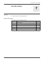
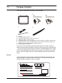
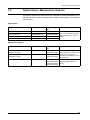
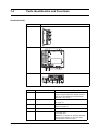
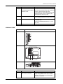
PFXGP4501TAAC http://www.axcontrol.com/automation/pro-face/gp-4000/PFXGP4501TAAC Pro-face Xycom GP4000 PFXGP4501TAAC Pro-face Xycom GP-450xT GP450xT Touch Screen Operator Interface 10.4 TFT Analog Color LCD Display with Conformal Coating. Call Now! 1-800-991-7026 [email protected] See Also: http://www.axcontrol.com/automation/pro-face/gp-4000 GP4000 Series Hardware Manual KanpaiHardwareManual 10/2011 GP4000 Series Hardware Manual Rear Mount Model 7 Overview This chapter presents the Rear Mount Model. What Is in This Chapter? This chapter contains the following sections. Section Topic Page 7.1 Package Contents 172 7.2 Certifications and Standards 173 7.3 Options Items/Maintenance Option 175 7.4 Parts Identification and Functions 176 7.5 Structural Specifications 182 7.6 Dimensions 184 7.7 Installation 220 171 7.1 Package Contents Verify all items listed here are present in your package: )RU *36HULHV 1 2 3 4 5 6 7 8 )RU *36HULHV GP unit: 1 DC power supply connector: 1 *1 USB cable clamp Type A: 1 set (1 clip and 1 tie) Installation gasket: 1 set (8 per set) Installation fasteners: 2 per set (attached to the top and bottom surfaces of the GP unit) Installation screws: 4 per set (attached to the top and bottom surfaces of the GP unit) GP4000 Series Rear Mount Model Installation Guide: 1 Warning/Caution Information: 1 This unit has been carefully packed with special attention to quality. However, should you find anything damaged or missing, please contact your local distributor. *1 You can use the DC power supply connector for GP-4300/4400 series to supply power to GP-4500/4600 series. However the reverse is not possible. You cannot use the DC power supply connector for GP-4500/4600 series on GP-4300/4400 series. Revision You can identify the product revision from the product label on the GP unit. The following diagram is a representation of Revision A. The product label indicates Revision A with an asterisk (*) in the "A" position. REV 172 * B C D E F G H I J K L M N O P Q R S T U V W X Y Z 1 2 3 4 5 GP4000 Series Hardware Manual 7.2 Certifications and Standards Introduction Pro-face submitted this product for independent testing and qualification by thirdparty listing agencies. These agencies have certified this product as meeting the following standards. Agency Certifications The GP unit is manufactured in accordance with: z UL 508 and CSA C22.2 n°142 for Industrial Control Equipment Note: z For use in Pollution Degree 2 environments. z For use on a flat surface of a Type 1 Enclosure. z 24 Vdc input panel must be used with a Class 2 power supply. Hazardous Substances The GP is a device for use in factory systems. When using the GP in a system, the system should comply with the following standards in regards to the installation environment and handling: z WEEE, Directive 2012/19/EU z RoHS, Directive 2011/65/EU z RoHS China, Standard SJ/T 11363-2006 CE Markings This product conforms to the necessary requirements of the following Directives for applying the CE label: z 2004/108/EC EMC Directive This conformity is based on compliance with EN61000-6-4, EN61000-6-2 For information on Standards and Regulations, such as certified models and certificates, see the following. http://www.pro-face.com/worldwide.html 173 DANGER POTENTIAL FOR EXPLOSION z z z z z z z Verify that the power, input and output (I/O) wiring are in accordance with Class I, Division 2 wiring methods. Substitution of any component may impair suitability for Class I, Division 2. Do not connect or disconnect equipment unless power has been switched off or the area is known to be non-hazardous. Securely lock externally connected units and each interface before turning on the power supply. Do not use, connect, or disconnect USB cable unless area is known to be nonhazardous. Do not disconnect while circuit is live or unless the area is known to be free of ignitable concentrations. Potential electrostatic charging hazard: wipe the front panel of the terminal with a damp cloth before turning ON. Failure to follow these instructions will result in death or serious injury. KC Markings ㌂㣿㧦㞞⌊ⶎG G ₆G㫛G⼚G ㌂ G㣿 G㧦 G㞞 G⌊ GⶎG G G h G₆₆G 㧊G ₆₆⓪G 㠛ⶊ㣿Oh PG 㩚㧦䕢㩗䞿₆₆⪲㍲G 䕦ⰺ㧦G ⡦⓪G ㌂㣿㧦⓪G O㠛ⶊ㣿G㏷䐋㔶₆㧦㨂PG 㧊G㩦㦚G㭒㦮䞮㔲₆G⧒ⳆSGṖ㩫㣎㦮G㰖㡃㠦㍲G㌂㣿䞮⓪Gộ㦚G⳿㩗 G 㦒⪲G䞿┞┺UG G G G 174 GP4000 Series Hardware Manual 7.3 Option Items / Maintenance Options This section explains the option items and maintenance options dedicated for use with the rear mount model. Read this section together with chapter 2, "Accessories" (see page 27). Option Items Product Name Model Number Corresponding GP Description unit 12.1-inch Overlay PFXZGPFSR12W1 PFXGP4601TADR Overlay (Front Sheet) for Flat Mount of GP4000 Series Rear Mount Model (Color: White, 1 piece) 10.4-inch Overlay PFXZGPFSR10W1 PFXGP4501TADR 7.5-inch Overlay PFXZGPFSR7W1 PFXGP4401TADR 5.7-inch Overlay PFXZGPFSR6W1 PFXGP4301TADR Product Name Model Number Corresponding GP Description unit 12.1-inch & 10.4-inch Rear mount Installation Fastener PFXZGPAFRL1 PFXGP4601TADR PFXGP4501TADR 7.5-inch & 5.7-inch Rear mount Installation Fastener PFXZGPAFRM1 PFXGP4401TADR PFXGP4301TADR Rear mount Installation Gasket PFXZGPWGR1 PFXGP4601TADR PFXGP4501TADR PFXGP4401TADR PFXGP4301TADR Maintenance Options Used to install the GP4000 Series Rear Mount model into a solid panel (2 pieces/ set). Includes the installation screws (4 pieces/set). GP4000 Series Rear Mount model Installation Gasket (1 piece) 175 7.4 Parts Identification and Functions PFXGP4301TADR Side PFXGP4301TADR Right $ % & Rear ' ( Bottom ' 176 * ) + , Part Name Description A USB (Type A) Interface Conforms to USB2.0 (Type A) x 1. Power supply voltage: 5Vdc+/-5%. Output Current: 500 mA or less. Maximum communication distance: 5 m (16.4 ft). B Serial Interface (COM1) RS-232C Serial Interface. Connector: D-Sub 9 pin (plug) x 1. C Serial Interface (COM2) RS-422/485 Serial Interface. Connector: DSub 9 pin (plug) x 1. D Power Plug Connector - E SD Card Access LED This lamp lights up when SD Card is inserted. ( see page 181) NOTE: Do not remove or insert the SD Card when the LED lamp is on. Doing so may damage data on the SD Card. GP4000 Series Hardware Manual Part Name Description F SD Card Interface Cover/Replacement Battery Insertion Cover For information on how to open the cover, and insert or remove the SD Card, refer to SD Card Insertion / Removal (see page 150). For information on how to open the cover and replace the battery, refer to Replacing the Primary Battery (see page 168). G USB (mini-B) Interface Conforms to USB2.0 (mini-B) x 1. Communication Distance: 5 m (16.4 ft) or less. H Ethernet Interface Ethernet transmission interface (10BASET/100BASE-TX) Connector: Modular jack (RJ-45) x 1. ( see page 181) I Maintenance LED ( see page 181) PFXGP4401TADR Side PFXGP4401TADR Right $ % & Rear ' ( Bottom ' ) * + , Part Name Description A USB (Type A) Interface Conforms to USB2.0 (Type A) x 1. Power supply voltage: 5Vdc+/-5%. Output Current: 500 mA or less. Maximum communication distance: 5 m (16.4 ft). 177 178 Part Name Description B Serial Interface (COM1) RS-232C Serial Interface. Connector: D-Sub 9 pin (plug) x 1. C Serial Interface (COM2) RS-422/485 Serial Interface. Connector: DSub 9 pin (plug) x 1. D Power Plug Connector - E SD Card Access LED This lamp lights up when SD Card is inserted. ( see page 181) NOTE: Do not remove or insert the SD Card when the LED lamp is on. Doing so may damage data on the SD Card. F SD Card Interface Cover/Replacement Battery Insertion Cover For information on how to open the cover, and insert or remove the SD Card, refer to SD Card Insertion / Removal (see page 150). For information on how to open the cover and replace the battery, refer to Replacing the Primary Battery (see page 168). G USB (mini-B) Interface Conforms to USB2.0 (mini-B) x 1. Communication Distance: 5 m (16.4 ft) or less. H Ethernet Interface Ethernet transmission interface (10BASET/100BASE-TX) Connector: Modular jack (RJ-45) x 1. ( see page 181) I Maintenance LED ( see page 181) GP4000 Series Hardware Manual PFXGP4501TADR Side PFXGP4501TADR Rear $ % Bottom + * & ' , ( ) Part Name Description A Power Plug Connector - B SD Card Access LED This lamp lights up when SD Card is inserted. ( see page 181) NOTE: Do not remove or insert the SD Card when the LED lamp is on. Doing so may damage data on the SD Card. C SD Card Interface Cover/Replacement Battery Insertion Cover For information on how to open the cover, and insert or remove the SD Card, refer to SD Card Insertion/Removal (see page 150). For information on how to open the cover and replace the battery, refer to Replacing the Primary Battery (see page 168). D USB (mini-B) Interface Conforms to USB2.0 (mini-B) x 1. Communication Distance: 5 m (16.4 ft) or less. E Ethernet Interface Ethernet transmission interface (10BASET/100BASE-TX) Connector: Modular jack (RJ-45) x 1. ( see page 181) F Maintenance LED ( see page 181) G USB (Type A) Interface Conforms to USB2.0 (Type A) x 1. Power supply voltage: 5Vdc+/-5%. Output Current: 500 mA or less. Maximum communication distance: 5 m (16.4 ft). H Serial Interface (COM1) RS-232C Serial Interface. Connector: D-Sub 9 pin (plug) x 1. I Serial Interface (COM2) RS-422/485 Serial Interface. Connector: DSub 9 pin (plug) x 1. 179 PFXGP4601TADR Side PFXGP4601TADR Rear $ % Bottom * & 180 + ' , () Part Name Description A Power Plug Connector - B SD Card Access LED This lamp lights up when SD Card is inserted. ( see page 181) NOTE: Do not remove or insert the SD Card when the LED lamp is on. Doing so may damage data on the SD Card. C SD Card Interface Cover/Replacement Battery Insertion Cover For information on how to open the cover, and insert or remove the SD Card, refer to SD Card Insertion/Removal (see page 150). For information on how to open the cover and replace the battery, refer to Replacing the Primary Battery (see page 168). D USB (mini-B) Interface Conforms to USB2.0 (mini-B) x 1. Communication Distance: 5 m (16.4 ft) or less. E Ethernet Interface Ethernet transmission interface (10BASET/100BASE-TX) Connector: Modular jack (RJ-45) x 1. ( see page 181) F Maintenance LED ( see page 181) G USB (Type A) Interface Conforms to USB2.0 (Type A) x 1. Power supply voltage: 5Vdc+/-5%. Output Current: 500 mA or less. Maximum communication distance: 5 m (16.4 ft). H Serial Interface (COM1) RS-232C Serial Interface. Connector: D-Sub 9 pin (plug) x 1. I Serial Interface (COM2) RS-422/485 Serial Interface. Connector: DSub 9 pin (plug) x 1. GP4000 Series Hardware Manual LED Indications (1)Maintenance LED WARNING UNINTENDED EQUIPMENT OPERATION You cannot check the maintenance LED from the front of the GP unit. z Design software by considering the possibility that touch operations may be performed while an error has occurred. z To prevent malfunctions caused by touch operations, design software so that switches and other controls arranged on the screen do not function when you want the screen to be off even if these controls are accessed with touch operations. *1 Failure to follow these instructions can result in death, serious injury, or equipment damage. *1 For details on the Standby Mode function and on the operations to use in the system data area to turn the screen off, read the "GP-Pro EX Reference Manual". Color Indicator Operation Mode (Drawing) Logic execution mode (when logic is enabled) Green ON Offline – In operation RUN STOP Flashing In operation Orange Flashing Software starting up. Red ON Power is turned ON. Flashing In operation LED fade (Green) ON The GP unit’s "Backlight Control" is set to Standby Mode and the screen has gone blank. - OFF Power is turned OFF. Major Error (2)SD Card Access LED Color Indicator Description Green (Active) ON The SD Card is inserted. OFF The SD Card is not inserted or is not being accessed. (3)Ethernet LED Color Indicator Description Green (Active) Flashing Data transmission is occurring. OFF No data transmission. Green (Link) ON Data transmission is available in 10BASE-T/100BASE-TX. OFF No connection or subsequent transmission failure. Link Active 181