1
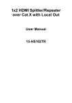
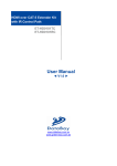
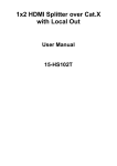
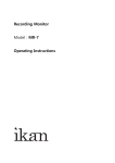
HDMI Source Tester
VA-1830
Instruction Manual
Ver 1.00
HDMI Source Tester
VA-1830
Instruction Manual
2009.11
Ver.1.00
ASTRODESIGN,Inc
Contents
Revision History.......................................................................................................................................................... iii
Safety Precautions ......................................................................................................................................................v
In order to ensure safe operation ............................................................................................................................v
Concerning the power cable....................................................................................................................................v
Concerning foreign matter ......................................................................................................................................vi
Concerning this product......................................................................................................................................... vii
Concerning impact................................................................................................................................................. vii
Concerning the installation .................................................................................................................................... vii
When trouble or malfunctioning has occurred ....................................................................................................... vii
Concerning the configuration of this manual ............................................................................................................ viii
What is packed with the machine ............................................................................................................................. viii
Chapter 1
About VA-1830 ............................................................................................................................................ 1
1.1. General descriptions............................................................................................................................................ 1
1.2. Features .............................................................................................................................................................. 1
1.3. Names and functions of each part ....................................................................................................................... 2
1.3.1. Front panel ................................................................................................................................................... 2
1.3.2. Rear panel.................................................................................................................................................... 3
1.4. Connection example............................................................................................................................................ 4
1.5. Version up............................................................................................................................................................ 6
Chapter 2
Operation..................................................................................................................................................... 7
2.1. Communication method....................................................................................................................................... 7
2.2. Terminal commands............................................................................................................................................. 8
2.3. Data storage of the Config (reference sample) data ............................................................................................ 9
2.3.1. Number of the storage data.......................................................................................................................... 9
2.3.2. Where to store the registered data ............................................................................................................... 9
Chapter 3
Specifications ............................................................................................................................................ 11
3.1. Main specifications .............................................................................................................................................11
3.1.1. Input and Output..........................................................................................................................................11
3.1.2. General specifications .................................................................................................................................11
i
ii
Before Use
Revision History
Ver.
Date
1.00
2009/3/
Page
Item
Description
Initial version
iii
iv
Before Use
Before Use
Introduction
Thank you for very much purchasing the model HDMI Source Tester VA-1830.
This manual contains details on the operation procedures to be followed when the VA-1830 is used, the
checkpoints and precautions to be observed, and so on.
Before using the VA-1830, please read through these instructions.
After reading the manual, keep it in a safe place for future reference.
Safety Precautions
Malfunctioning or trouble may result if this product is not handled properly. Before proceeding to operate the
product, be absolutely sure to read the safety precautions set forth below to ensure proper operation.
In order to ensure safe operation
■ Do not subject the switcher to impact or throw it. Doing so may cause the switcher to
malfunction, explode or generate abnormally high levels of heat, possibly resulting in a
fire.
■ Do not use the switcher where there is a danger of ignition or explosions.
■ Do not place the switcher inside a microwave oven or other heating kitchen appliance or
inside a high pressure vessel. Doing so may heat up the switcher to abnormally high
levels, cause smoking, running the risk of the switcher’s catching fire and/or damaging
the circuit components.
■ This machine contains some high-voltage parts. If you touch them, you may receive an
electric shock and burn yourself so do not attempt to disassemble, repair or remodel the
switcher.
■ If there is a thunderstorm while the switcher is being used outdoors, immediately turn off
its power, disconnect the power cable from the main unit, and move the switcher to a
safe place.
Concerning the power cable
■ Always take hold of the molded part of the plug when disconnecting the power cable.
■ Do not use force to bend the power cable or bunch it up for use. Doing so may cause a
fire.
■ Do not place heavy objects on top of the power cable. Doing so may damage the cord,
causing a fire or electrical shock.
v
Concerning foreign matter
■ Do not spill liquids inside the monitor or drop inflammable objects or metal parts into it.
Operating the switcher under these conditions may cause a fire, electric shocks and/or
malfunctioning.
vi
Before Use
Concerning this product
■ When connecting this product to another unit (such as a TV set or DVD player), use the
FG cable provided or a similar cable to connect the frame ground (FG) terminal on the
other unit to the frame ground (FG) terminal on the VA-1830. Failure to connect these
terminals may cause the product to fail or malfunction.
Fig.
Connecting the FG terminals
VA-1830
Concerning impact
■ This is a precision instrument and, as such, subjecting it to impact may cause
malfunctioning. Take special care when moving the machine.
■ Do not drop the machine.
Concerning the installation
■ Install the switcher in a stable location. Do not stand the switcher on one of its sides.
Doing so may cause the switcher’s temperature to rise due to heat generation, possibly
resulting in malfunctioning.
When trouble or malfunctioning has occurred
■ In the unlikely event that trouble or malfunctioning should occur, disconnect the
machine’s power cable, and contact your dealer or an ASTRODESIGN sales
representative.
vii
Concerning the configuration of this manual
This manual contains the instructions for operating the VA-1830. It is configured as shown in the table below,
and it describes the control methods, precautions and other aspects. Read through the manual carefully to
ensure that the machine will be operated properly.
Chapter
Description
Introduction
This chapter describes the safety precautions, configuration of the manual
and what is packed with the machine.
1 About VA-1830
This chapter gives an overview of the VA-1830 and describes its features.
2 Operation
This chapter describes the methods used to control the VA-1830.
3 Specification
This chapter describes the VD-1673’s specifications.
What is packed with the machine
The machine comes with the following items. Be absolutely sure to use only the genuine accessories which are
supplied with this switcher since the use of any non-designated items may cause malfunctioning.
■ Standard accessories
viii
Contents
Quantity
VA-1830 Maun unit
1
VA-1830 Instruction Manual CD(PDF) or book
1
Power cable
1
FG cable
1
1
About VA-1830
1.1. General descriptions
This is a HDMI Source Tester to check the function of HDMI output automatically.
It can check video, audio,
DDC line and CEC line signal automatically.
By using the THROUGH mode, it can check the status of DDC and CEC lines between the Source and Sink
device that are connected to the VA-1830.
1.2. Features
■ Auto test of HDMI output.
By making the Config data (reference sample data) by PC, it can perform the auto test.
■ Confirm the HDMI video output.
It can confirm the video signal that is input to VA-1830.
■ Confirm the HDMI audio output.
It can confirm the level and the frequency of the audio signal that is input to the VA-1830.
■ Confirm the HDMI control signal
It can confirm the control signal that is input to the VA-1830.
■ Confirm the DDC and CEC lines.
It can confirm the DDC commands or CEC commands that are sent to the VA-1830.
■ THROUGH mode
By using the THROUGH mode, it can confirm the communication status between the Source device and the
Sink device that are connected to the VA-1830.
1
1.3. Names and functions of each part
1.3.1. Front panel
Fig. front panel
List
Number
Names
1
THROUGH LED
Names and functions
Functions
It shows THROUGH Mode. (lighting : THROUGH mode active)
It is also used to confirm the setting completion and the version
up completion.
Please refer to the “VA-1830 Terminal
Command Manual” for details.
2
2
POWER LED
It shows power ON/OFF (lighting : power ON)
3
POWER Switch
It is used to set ON/OFF of the VA-1830’s power.
Chapter 1 About VA-1830
1.3.2. Rear panel
Fig. Rear panel
List
Names and functions
Number
Names
Functions
4
RS-232C
By connecting with PC via RS-232C, VA-1830 is controlled by the
transmission of the commands.
5
LAN
Using the Ethernet cable, LAN connection is established.
VA-1830 is controlled by the transmission of the commands.
6
USB-A
Standard USB FLASH is connected.
7
USB-B
By connecting with PC via USB, VA-1830 is controlled by the
transmission of the commands. Please refer to the “VA-1830
Terminal Command Manual” for details.
8
HDMI OUT
HDMI output of the VA-1830.
Only when THROUGH mode is used, HDMI signal is output.
9
HDMI IN
HDMI input of the VA-1830.
3
1.4. Connection example
■ Confirms the output of the Source device.
Host Computer
Source device
Connect either port to control VA-1830
Fig Connection example 1
■ Confirms the DDC and CEC lines between the Source and the Sink
Source機器
Source device
AC IN(100-240V) T3.15A
RS-232C
MODEL:
SER.No:
MADE IN
JAPAN
USB
LAN
HDMI OUT
2
1
SinkSink機器
device
Host computer
ホストコンピュータ
VA-1830を制御するために
Connect either port
どれかと接続
to control VA-1830.
Fig
4
Connection example 2
HDMI IN
Chapter 1 About VA-1830
■ Save the setting data in the external memory.
Host computer
USB memory
Connect
either
port
to
control VA-1830.
Fig
Connection example 3
5
1.5. Version up
Version up is performed by using the USB flash.
(1) Save the [VerUp] folder of the version up data in the root folder of the USB flash.
VerUP
Root Folder
VA1830Boot.bin
Firm
VA1830Std.bin
mainFpga
CPU_BOOT.bin
CPU_Vxxx.bin
Fig
(2) Turn off the VA-1830.
Structure of the version up data.
Insert the USB flash to the VA-1830.
(3) Turn on the VA-1830.
(4) After a few seconds, the THROUGH LED of the front panel blinks.
caution
6
Version up completes.
Please do not turn off the power of the VA-1830 during version
up.
2
Operation
The operation is performed by sending the commands from the PC.
2.1. Communication method
There are 3 kinds of communication method between PC and the VA-1830.
List
Control method
Control method
Description
RS-232C port
Connect RS-232C ports of the VA-1830 and PC by straight cable.
LAN port
Connect LAN ports of the VA-1830 and PC by cross cable. Or, use the
hub of the LAN, and connect by straight cable.
Connect the USB-B port of the VA-1830 and USB-A port of the PC by
USB port
cable.
■ RS-232Cconnection
Host computer
RS-232C straight
Fig. Connection by RS-232C port
■ LAN connection
Host computer
straight
straight
Hub
Fig
Connection by LAN port (using the hub)
7
Host computer
Cross
Fig.
Connection by LAN port (direct)
■ USB connection
Host computer
A connector
B connector
Fig.
Caution
Connection by USB port
When connecting by LAN, it is necessary to set the parameter of
the LAN, such as IP address by other control methods.
2.2. Terminal commands
Please refer to the “VA-1830 Terminal Commands Manual” about the details of the commands.
8
Chapter 2 Operation
2.3. Data storage of the Config (reference sample) data
The Config (reference sample) data can be saved in the VA-1830 main unit or USB flash.
Even you turn off
the power of VA-1830, the data can be maintained.
2.3.1. Number of the storage data
List
Number of the storage data
Device
Storage number
VA-1830 Main unit
10 (0 to 9)
USB Flash
256 (0 to 255)
2.3.2. Where to store the registered data
The data that is saved in the USB flash is placed below.
Fig. where to store the data
9
10
3
Specifications
3.1. Main specifications
3.1.1. Input and Output
List Input and Output specification
Item
Standard
HDMI
TMDS clock
Input /
Video Timing
25MHz to 225MHz (12bit/150MHz)
Pixel clock
Output
25MHz to 165MHz
(Up to 150MHz in case of
Deep Color 12bit)
H Total
4096 pixel
H Active
2048 pixel
H Blanking
2048 pixel
V Total Line
4095 line
V Active
2047 line
V Blanking
2047 line
Deep Color
8, 10, 12bit
Color space
RGB/YCbCr444, 422
HDCP
Available
Audio
(ver.1.3)
Sampling frequency: 32 to 192kHz
Channel number : 8CH
High Bit Rate Audio supported
DDC
DDC2B
E-EDID
Ver.1.4
CEA EDID Timing Extension
CEA-861-E
3.1.2. General specifications
List
General specifications
Item
Description
Power supply voltage
AC100 – 240V
Frequency
50 / 60 Hz
Power consumption
15W
Dimensions
210(W) x 44(H) x 240(D)
Weight
1.3kg
Operating temperature
5 – 40℃
Operating humidity
30 – 80 % RH (no condensation)
11
12
VA-1830
Instruction Manual
NOTICE
● An incorrectly collated manual or a manual with missing pages will be
replaced.
● All copyrights pertaining to this product are the property of ASTRODESIGN.
● This manual may not be copied in whole or in part without written
permission.
● The contents of this manual are subject to change without prior notice due
to improvements.
● The manufacturer will not be liable for any effects caused by incorrect
operation.
● All inquiries concerning this product should be addressed to your dealer or
to the manufacturer at the contact numbers given below.
● The products and product names mentioned in this manual are the
trademarks and registered trademarks of the companies concerned.
T0172