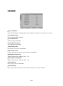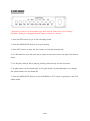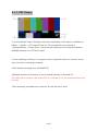
1
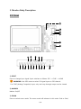
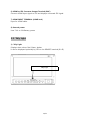
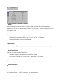
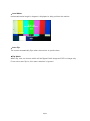
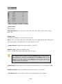
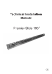
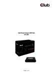
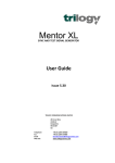
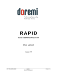
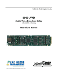
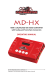
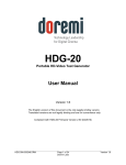
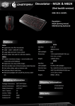
Recording Monitor
Model : MR-7
Operating Instructions
Safety Instructions
● Keep monitor away from heat.
● Do not use the monitor in water or under conditions with high humidity or excessive
dust.
● Turn off the power and unplug the power cord, if the monitor or the monitor casing is
broken by a hit or fall.
● Refrain from using the monitor near high RF or other sources of electromagnetic
interference, this may affect the monitor’s performance or cause the monitor to fail.
● Use of the monitor in hostile or extreme environmental conditions may affect
performance or cause the unit to fail.
● Excessive vibration or physical shock may cause the monitor to fail. (This excludes
typical broadcast vehicle application.)
● Keep the monitor at a reasonable distance (at least 50 cm) away from wall or other
objects to allow proper air circulation, otherwise it may cause problems or failure of the
unit.
● Do not take apart the monitor or insert foreign objects. Disassembling may cause
defects to the unit and is not covered under warranty.
● Do not drop or subject monitor to extreme, rough use, it may cause defects to the
unit and is not covered under warranty.
● Do not use AC Power Cord and DC Adaptor simultaneously, it may cause defects to
the unit.
● Before connecting external equipment, unplug the power. After connecting external
equipment, plugin the AC power and power on the monitor. Otherwise, monitor may
cause defects to external equipment due to static electricity.
● If the monitor produces smoke, strange sounds or smells, disconnect the power and
2/51
power down the unit. Then, contact ikan immediately.
● Do not disassemble or modify the monitor, it may cause fire, electric shock and other
damage. This act will void the warranty.
● Using the monitor for an extended period of time on a freezed frame or static image
may cause stained appearance or residual image. Solution: run a white signal to the
monitor for one to two hours.
● The monitor cannot be warranty serviced for problems due to the end-user's own
gamma and color calibration settings.
● Do not insert or remove the SD card during read/write. It may damage video files as
well as the monitor.
3/51
Thank you for purchasing an ikan monitor. Please read the instruction manual before
installation or use of the monitor. Please contact our service center or sales team if any
problem occurs.
Table of Contents
1. Monitor Outline• • • • • • • • • • • • • • • • • • • • • • • • • • • • • • • • • •
6
2. Monitor Features • • • • • • • • • • • • • • • • • • • • • • • • • • • • • • • •
6
3. Monitor Body • • • • • • • • • • • • • • • • • • • • • • • • • • • • 7
3-1. Front • • • • • • • • • • • • • • • • • • • • • • • • • • • • • • • • • • • • • •
7
3-2. Rear • • • • • • • • • • • • • • • • • • • • • • • • • • • • • • • • • • • 10
3-3. Tally Light• • • • • • • • • • • • • • • • • • • • • • • • • • • • • • • • • • • • • • • 11
3-4. Function Assignment to F1, F2 buttons • • • • • • • • • • • • • • • • • • • 12
4. Status Display • • • • • • • • • • • • • • • • • • • • • • • • • • • • • 13
5. Configuration Menu • • • • • • • • • • • • • • • • • • • • • • •• • • • • • 14
5-1. VIDEO • • • • • • • • • • • • • • • • • • • • • • • • • • • • • • • • • 16
5-2. DISPLAY • • • • • • • • • • • • • • • • • • • • • • • • • • • • • • • • 18
5-3. DISPLAY 2 • • • • • • • • • • • • • • • • • • • • • • • • • • • • • • • 19
5-4. DISPLAY 2 • • • • • • • • • • • • • • • • • • • • • • • • • • • • • • • 21
5-5. COLOR • • • • • • • • • • • • • • • • • • • • • • • • • • • • • • • •
23
5-6. MARKER • • • • • • • • • • • • • • • • • • • • • • • • • • • • • • • • 24
5-7. OSD • • • • • • • • • • • • • • • • • • • • • • • • • • • • • • • • • • 26
5-8. AUDIO • • • • • • • • • • • • • • • • • • • • • • • • • • • • • • • • 30
5-9. GPI • • • • • • • • • • • • • • • • • • • • • • • • • • • • • • • • • • • • 31
5-10. SYSTEM • • • • • • • • • • • • • • • • • • • • • • • • • • • • • • • • 32
6.REC Mode
••••••••••••••••••••••••••••••••
34
6-1-1. REC Display • • • • • • • • • • • • • • • • • • • • • • • • • • • • • • • 35
6-1-2. Manual Recording • • • • • • • • • • • • • • • • • • • • • • • • • • • • • • • • • 36
6-2. List Screen • • • • • • • • • • • • • • • • • • • • • • • • • • • • • 37
6-3. Play Screen • • • • • • • • • • • • • • • • • • • • • • • • • • • • • • • • 38
7. Remote Terminal Assignment
••••••••••••••••••••••
7-1. Remote Terminal (RJ-45) Assignment
39
• • • • • • • • • • • • • 39
7-2. GPI Port (RJ-45) Connection Use • • • • • • • • • • • • • • • 39
7-3. Remote Terminal Assignment (GPI Port)• • • • • • • • • • • • • 40
8. Program Update Port Instruction • • • • • • • • • • • • • • • • • • • 41
9. List of Compatible Signal formats (HDMI/COMPOSITE) • • • • • 42
9-1. List of Compatible Signal formats (SDI) • • • • • • • • • • • • • •
4/51
43
10. Specifications
••••••••••••••••••••••••••••••
44
11. Dimensions • • • • • • • • • • • • • •• • • • • • • • • • • • • • 45
12. Troubleshooting • • • • • • • • • •• • • • • • •
• • • • • 46
13. Maintenance • • • • • • • • • • • • • • • • • • • • • • • • • • • • • 48
14. Monitor change • • • • • • • • • • • • • • • • • • • • • • • • • • • • •
48
15. Items to be confirmed for menu control • • • • • • • • • • • • • • • • • • 48
16. Directions for monitor installation • • • • • • • • • • • • • • • • • 48
5/51
1. Monitor Overview
The MR-7 Monitor supports video signals ranging from standard HD/SD-SDI , Composite
and HDMI. This multi-format monitor is designed for demanding broadcast applications,
and features: HDMI-to-SDI converted loop-through, real-time recording, high visibility
under sunlight and robust housing. The MR-7 can be used on-camera, and is designed
for indoor or outdoor use.
2. Monitor Features
•
SMPTE-425M 3G Signal supported (Level A, Level B)
•
Various signal input acceptable (HD/SD-SDI, HDMI, CVBS)
•
HDMI-to-SDI conversion with 1:1 resolution mapping (monitor restart is not
required)
•
Input signal encoded with H.264 Video Codec
•
Max 32GB SDHC card supported
•
Low-reflection LCD for outdoor
•
Toggle button for instant daytime mode in sunlight.
•
Auto Flip
•
Level Meter
•
Various Markers (4:3, 13:9~16:9, 1.85:1, 2.35:1, user-defined)
•
False Color On/Off
•
Exposure Y/C Range Checker
•
Focus Assistance
•
Waveform Display
•
Vectorscope Display
•
VU Level Meter up to 1~16 channels
•
Tally Display/Tally LED Control Output
•
H/V Delay
•
Firmware updates via USB memory
6/51
3. Monitor Body Description
3-1. Front
17
18
19
20
21
22
16
①
② ③
⑮
④ ⑤ ⑥
⑭
⑦
⑬
⑫
⑧ ⑨ ⑩
⑪
1) INPUT
Press to change input signal. Input switches as follows: SDI -> CVBS -> HDMI
!
WARNING: Use OSD menu to select 3G signal input on SDI channel.
For CVBS (Analog Composite) input, only one loop-through output can be viewed.
2) MARKER
Marker On/Off
3) ZOOM
Press to switch zoom mode. The zoom mode will advance in this order: Pixel to Pixel,
7/51
User Zoom (adjustable by up/down knob), 5D Mark II Zoom.
In some cases, the dot indicator for Zoom may not be shown on SDI 720p format.
4) WF/VS
The WF/VS button changes the display in this order: Waveform, Vectorscope,
Waveform/Vectorscope, Wide Waveform, Full Waveform, Full Vectorscope and WF/VS Off.
5) Daylight
Switch the backlight luminance. Backlight luminance will change in this order: Indoor
(Normal), Outdoor (Brighter), Daylight (Brightest).
Format, On the list menu, works as Format SD function
6)7) Function Keys (F1, F2)/SLOW/CMD
User defined. A function can be assigned for each function button.
SLOW : Change playback speed slower between 1/2 to 1/8 speed.
CMD : Opens the command dialog of the list menu.
(Selectable commands are Delete/Copy/Format/Rename/Auto Naming)
On playback of a recorded file, this button works as info On/Off, Volume Setting or
Delete button.
8) LIST/Q_Play
Press and hold for 2 seconds: Enters Playback mode.
Q_PLAY, Plays the latest recorded file. The latest file information is lost when monitor is turned off.
9) MENU
Opens the OSD menu.
10) REC
Start recording.
11) Knob KEY
Brightness, Contrast, Chroma, Phase is adjustable by pressing knob.
On OSD menu or Playback, knob is used to move cursor, select file, or press OK.
12) STOP
Stop recording/playback in record mode.
8/51
13) DEL
Delete a selected file.
14) Tally Light
Red, Green, Amber
15) SEL.ALL
Select all recorded clips on the list screen.
16) SEL
Select one recorded clip on the list screen.
17) SD Card Slot
Use a Class 4 or higher SDHC card. SDXC are NOT compatible.
18) REMOTE Port (RJ-45 Jack)
An external GPI type control port
For details, refer to: 7. Remote Terminal Assignment (p.39).
19) UPDATE Port (USB Port)
A communication terminal to update firmware.
On Firmware Update mode, DAYLIGHT, F1 button LEDs will be blinking one by one, and
'Update Mode' will be displayed on the bottom left of the screen
20) PGM/UPDATE Port (Mini USB Jack)
A communication terminal to update firmware, control with Wall System Controller, or
adjust color temperature. For details, refer to: 8. Program Update Port Instruction
(p.41).
21) Headphone Jack
Connect 1/8” (3.5 mm) stereo headphone to monitor audio.
22) Power selection switch
Choose from INT (Battery), OFF, or EXT (External) power.
9/51
3-2. Rear
②
③
④
⑤
⑥
⑦
①
⑧
1) DC power input terminal
It supplies DC power. Please check DC rated input voltage.
For DC Adaptor, it can be used from about 7V to 24V for 12V, Battery power.
WARNING: Check power sources and power supply accessories for
compatibility with monitor.
2) SDI 1 input terminal (BNC)
HD/SD-SDI signal input terminal.
Per SMPTE standard, SDI signal input includes Audio signal.
3) SDI-LOOP OUT TERMINAL (BNC)
Output terminal that displays the HD/SD-SDI input signal.
Not displayed when the monitor power is off. (Active Select Output)
4) CVBS (Composite) INPUT TERMINAL (BNC)
Input terminal for CVBS (Composite) signal.
5) CVBS (Composite) OUT TERMINAL (BNC)
Output terminal that displays the CVBS (Composite) input signal.
10/51
6) HDMI to SDI Converter Output Terminal (BNC)
Converts HDMI input signal to SDI and displays converted SDI signal.
7) HDMI INPUT TERMINAL (HDMI Jack)
Input for HDMI cable.
8) Internal power
Uses 7.4V to 24V Battery power.
3-3. Tally Light
1) Tally Light
Displays three colors: Red, Green, Amber.
It can be displayed optionally by GPI on the REMOTE terminal (RJ-45).
Tally Light
11/51
3-4. Function Assignment for F1, F2
17 assignable functions are in the System section of OSD Menu.
User Defined Functions:
● ALM (Audio Level Meter) Display On/Off
● Anamorphic On/Off
● Aspect On/Off
● 1:1 Scan On/Off
● Direct Zoom
● TC (Time Code) Display On/Off
● Video Range Check On/Off
● Focus Peaking Display On/Off
● False Color On/Off
● Freeze On/Off
● H/V Flip On/Off
● Video Loss Alarm On/Off
● Video Loss Tally On/Off
● Direct User Marker
● Level Reset
● Audio Mute On/Off
● H/V Delay On/Off
● Scan On/Off
● R/G/B/Mono On/Off
12/51
4. STATUS DISPLAY
A function displayed on screen that checks the operating status of the monitor. Some of
the functions may not be displayed according to the options on monitor.
Display Left
CH-1, 3, 5 ~
15
Display Right
CH-2, 4, 6 ~
16
Vector Scope
또는 Waveform
Waveform 또는
Vector Scope
13/51
1) VU Level Meter Display
Can be turned On or Off in the Audio MENU configuration, or assigned to the
function keys on the front.
▶ On: Left (displays even CH), Right (displays odd CH).
▶ Off: It turns off the display of Level Bar.
▶ VU Meter Position: Top/Bottom selectable.
2) Waveform/Vectorscope Display
Monitor switches between Waveform, Vectorscope, 2x Waveform, Waveform &
Vectorscope together.
▶ Waveform or Vectorscope screen position can be adjusted to Left Top, Right Top, Left
Bottom, or Right Bottom on the Display section of the CONFIG Menu.
The display position is changed by Up (▲), Down (▼) buttons.
If interlaced input signal freezes for a long time, it may cause the
waveform to stick.
SDI 2Ksf signal may cause the Vectorscope to stick if the video freezes.
However, this may disappear after the video starts moving.
When using the HD-SDI format some areas may look distorted during
scaling of the Vectorscope.
14/51
5. CONFIGURATION MENU
1. Press the MENU button and CONFIG menu will be shown.
2. Move to items to configure or change using UP (CW) ▲ or DOWN (CCW) ▼ of the
Knob KEY, then press the Knob KEY (Push-ENTER) to select.
3. Turn the Knob KEY using UP (CW) ▲ or DOWN (CCW) ▼ on the selected Menu item
to adjust.
4. Press the MENU button to go back to the previous item. If the MENU button is
pressed continuously the Exit Menu screen is terminated.
CONFIG MENU may disappear if there is no signal detected, Or if MENU is
configured while the signal is unstable, the operation may be delayed or could
cause the wrong operation.
CONFIG MENU settings are saved by the input signal mode. Therefore, please
check the input mode on the bottom of the applicable menu just in case there
were changes made to the configuration status.
Alert: The LCD pixels may freeze if there is no movement on the video for an
extended amount of time.
15/51
5-1. VIDEO
▪ Brightness: Adjusts the perceived emitted/reflected light.
▪ Contrast: Adjusts perceived lightness/darkness.
▪ Chroma (HUE): Adjusts color saturation.
▪ Phase: Adjusts the screen color (status).
▪ Sharpness: Adjusts the clarity or crispness of the image.
▪ SDI 3G Mode: Indicates HD-SDI 3G signal use.
▪ SDI Switching: Stabilizes the screen when format signals are changed on Matrix
Boards or Routing Switchers.
- Normal: The screen may blink if the default setup is changed as the signal is
connected.
- Fast: Used to display a stable screen by minimizing changes of the screen.
▪
NTSC Setup: Selects 0 IRE, 7.5 IRE.
Operated on 7.5 IRE -> NTSC or SD level YUV model.
▪ Mosquito Filter: Filters the noise which occurs when processing a compressed signal.
▪ HDMI UV Swap: UV signal may change the display when the HDMI Mode is normal
and the input signal is set on graphic resolution; this function is used to display normal
color. [color space YUV-VS-RGB]?
▪ HDMI Mode
- Normal: Signal input only available.
- Convert: Display is available simultaneously with signal input and HDMI to SDI OUT.
16/51
Signals supported on SDI 3G Mode are as follow: (SMPTE-425M)
▶ A_MS1_YCbCr422_10
: 3G SDI Level-A Mapping Structure 1 – YCbCr 4:2:2/10 bit
▶ A_MS2_YCbCr444_10
: 3G SDI Level-A Mapping Structure 2 – YCbCr 4:4:4/10 bit
▶ A_MS2_RGB444_10
: 3G SDI Level-A Mapping Structure 2 – RGB 4:4:4/10 bit
▶ A_MS3_YCbCr444_12
: 3G SDI Level-A Mapping Structure 3 – YCbCr 4:4:4/12 bit
▶ A_MS3_RGB444_12
: 3G SDI Level-A Mapping Structure 3 – RGB 4:4:4/12 bit
▶ A_MS4_YCbCr422_12
: 3G SDI Level-A Mapping Structure 4 – YCbCr 4:2:2/12 bit
▶ B_MS1_YCbCr422_10
: 3G SDI Level-B Mapping Structure 1 – YCbCr 4:2:2/10 bit
▶ B_MS2_YCbCr444_10
: 3G SDI Level-B Mapping Structure 2 – YCbCr 4:4:4/10 bit
▶ B_MS2_RGB444_10
: 3G SDI Level-B Mapping Structure 2 – RGB 4:4:4/10 bit
▶ B_MS3_YCbCr444_12
: 3G SDI Level-B Mapping Structure 3 – YCbCr 4:4:4/12 bit
▶ B_MS3_RGB444_12
: 3G SDI Level-B Mapping Structure 3 – RGB 4:4:4/12 bit
▶ B_MS4_YCbCr422_12
: 3G SDI Level-B Mapping Structure 4 – YCbCr 4:2:2/12 bit
▶ B_2X_DS1_YCbCr422_10
: 3G SDI Level-B Data Stream 1 – YCbCr 4:2:2/10 bit, Dual Link SMPTE-372M
▶ B_2X_DS2_YCbCr422_10
: 3G SDI Level-B Data Stream 2 – YCbCr 4:2:2/10 bit, Dual Link SMPTE-372M
Configuring as normal on 3G SDI signals, most Level-A signals are recognized automatically, but
some special cases formats must be configured manually for recognition.
In the case of 3G Level-B signal, the applicable format must be configured manually to recognize the
signal, and may not recognize the signal if the power is Off/On. In this case, turn the power On/Off
or change the channel and come back. This should allow you to operate it normally.
17/51
5-2. DISPLAY 1
▪ Aspect
Switches the screen between 16:9, Fill, Native Ratio (original ratio) for Format input.
The aspect will not be changed even if Aspect 16:9 function is selected if the source is in
16:9 aspect ratio.
▪ 1:1 Scan
- Displays the screen as Pixel Size on ON -> SD mode.
- Displays the screen according to the LCD size on OFF -> SD mode.
* Not configured or operated for HD signal
▪ Anamorphic
Resizes the images and display so that the screen can be seen as 11 screen modes
such as 3.56:1, 2.74:1, 2.59:1, 2.55:1, 2.40:1, 2.39:1, 2.35:1, 1.85:1, 1.75:1, 1.66:1, 1.37:1.
▪ Waveform Display
Selects the display mode of Waveform.
- Normal : Displays the waveform on the whole screen.
- Line Select : Displays the certain lines of waveform on the screen.
▪ Waveform Line Select
Used to select the desired line when Waveform Display Mode is in Line Select Mode.
▪ Waveform Select :
Select among Composite Y, Cb, Cr to show as waveform.
▪ Waveform Color Mode:
A Single waveform or Y/Cb/Cr waveforms can be displayed.
18/51
▪ Waveform Intensity :
Sets waveform display color strength between 0~63.
▪ WFM & Vector Size :
Waveform & Vector size is selectable between 3 sizes.
* Y/Cb/Cr :
Is NOT a color signal. It is a digital color expressing method based on luminance Y
and color difference signal Cb, Cr. Y means brightness, Cb means the strength of
blue and Cr means the strength of red.
▪ WFM & Vector Intensity:
Adjusts translucent degrees of window of waveform displayed on the window for
waveform, vector window.
19/51
5-3. DISPLAY 2
▪ Video Range Check (for SDI only)
Displays the area out of Y, Cb, or Cr range that user set. It is useful to check overexposed and under-exposed area on the screen.
▪ Y Range Max & Min:
Configures the Max and Min of Y values desired to classify.
▪ C Range Max & Min:
Configures the Max and Min of C values desired to classify.
▪ Color:
Color selection to represent over-exposed/under-exposed area. Black, Blue, Green, Red
are selectable.
▪ Blink Time:
Configures the color time of Blink Color and original signal, and the configuration is
available in increments between 1 ~ 5 seconds.
20/51
▪ Focus Peaking Display:
Highlights the edge of objects for sharp focus.
▪ Peaking Color:
Configures the color of highlighted edge.
Blue, Green, Red are selectable.
▪ Peaking Width:
Configures the width of highlighted edge as 0 to 48 steps.
21/51
5-4. DISPLAY 3
▪ False Color:
Checks the luminance and display different colors for each exposure level. This helps
users checking over-exposed and under-exposed areas of the image.
* When the input signal is dithered 10-bit or 12-bit, some gradient might look like noise.
22/51
▪ Level Meter:
Horizontal/vertical angle in degrees is displayed to help position the monitor.
.
▪ Auto Flip:
The screen automatically flips when the monitor is upside down.
▪ Flip Mode:
When flip, user can choose which will be flipped. Both image and OSD or image only.
If user turns auto flip on, this menu selection is ignored.
23/51
5-5. Color
▪ Color Temperature: Configures color temperature of the screen or White Balance.
There are 6, such as: VAR, 3200°K, 5400°K, 6500°K,9300°K, USER.
5 modes, excluding USER mode, are preset and users cannot modify. However, on USER
mode, users may change the color temperature by changing RGB Gain and Bias.
▪ VAR Number: The configuration is available by selecting among 1 ~ 63 steps. The
setup range is about from 3000°K to 9300°K.
▪ R, G, B Gain: It adjusts each Gain of R, G, B on USER mode.
▪ R, G, B Bias: It adjusts each Bias of R, G, B on USER mode.
Color Matrix Parameters are based on the ITU Color Standard.
The EBU Color configuration standard is based on the best appearance of
color for SDTV (ITU-R BT.601), HDTV (ITU-R BT.709) on LCD panels.
For Color Temperature (White Balance) adjustment, please use the
appropriate color calibration equipment.
24/51
5-6. MARKER
▪ Marker Ratio:
Selects Marker.
Selectable Markers: 4:3, 4:3 on-air, 16:9, 15:9, 14:9, 13:9, 1.85:1, 2.35:1, User1, User2,
User3, OFF.
▪ Safety Area:
Configures the display of valid area on the screen.
Mode : 95%, 93%, 90%, 88%, 85%, 80%, EBU Action 16:9, EBU Graphic 16:9, EBU Action
14:9, EBU Graphic 14:9, EBU Action 4:3, EBU Graphic 4:3, Off.
▪ Center Marker: Toggles the center marker (+) ON/OFF.
▪ Marker Color: Selects the Marker color.
Color -> White, Red, Green, Blue, Gray, Black (6 types)
The marker must be turned on by the MARKER button on the front so
that functions of submenu are displayed from MARKER menu. If the
Marker is off, then menu is not displayed on the screen even if the
submenu items are turned on.
▪ Marker Mat: Set the opacity of the area out of the safety area : Off, Half Black, Black
▪ Marker Thickness: Sets the Marker line thickness from 1 to 10 Pixels.
▪ User Marker H1: Sets the left location of vertical direction of the Marker.
25/51
▪ User Marker H2: Sets the right location of vertical direction of the Marker
▪ User Marker 1: Sets the top location of the horizontal direction of the Marker.
▪ User Marker V2: Sets the bottom location of horizontal direction of the Marker.
For User Marker location adjustment, it shall be configured as User1,
User2, User3 modes on the Marker Ratio.
26/51
5-7. OSD
▪ Timecode Display
Configures whether or not to display TC (Time Code) Data embedded in HD/SD-SDI
signal entered on the monitor screen. Displays as HH:MM:SS:FF.
▪ Timecode Position
Sets the position of the Time Code display. There are two positions: Top/Bottom .
27/51
The Monitor Recognizes
LTC in HANC, VITC1 in HANC , VITC2 in HANC, DVITC (SD-SDI).
① LTC (Longitudinal Time Code) :
Is saved on the Audio Track, Cue, or Address Track of the Video Tape, and
the specification is SMPTE-12M, IEC461.
② VITC (Vertical Interval Time Code) :
VBI is stored on the Video Track of Video Tape. VITC Code is composed as
90 bit which is 10 bit added more to classify individual field with
Redundancy Check on the LTC Code. The specification is SMPTE-12M,
IEC461.
③ DVITC (Digital Vertical Interval Timecode) :
Digitizes Analog VITC Waveform as 8bit or 10bit, used for Digital Video
System. The specification is SMPTE-266M, ITU-T BT.1366.
If the purchased monitor is 7-inch, please configure as DVITC (SD-SDI).
For HD-SDI 1920*1080/60i signal, LTC is located on line10,
VITC1 is
located on line9, VITC2 is located on line571. The specification is SMPTE
RP-188, ITU-T BT.1366.
For this monitor, please configure as follow on Time Code Menu.
- LTC in HANC : located on Line 1.
- VITC1 in HANC : located on Line 9.
- VITC2 in HANC : located on Line 571.
28/51
▪ OSD Display Time
Configures display time (sec) of MENU and displayed on the screen. The configuration is
available from 0 (Continue) to 60 seconds.
▪ OSD Blend
Configures the transparency of MENU and MENU window displayed on the screen from
0 to 15 levels. Select 0 for absolute opaque, and the higher value will be higher
transparency.
▪ OSD Position
Configures the position of MENU displayed on the screen.
5 positions such as Left Top, Right Top, Left Bottom, Right, Bottom, Center can be
designated.
▪ Internal Pattern
Displays the internal patterns, which are built in the monitor. The format and resolution
of the patterns are 1080/30p.
Internal Patterns: 100% Color Bar, 75% Color Bar, RP219, Blue, Green, Red, 100% (White)
~ 0% (Black).
▪ Source ID Display
Toggles the display of Source ID text on the monitor screen.
▪ Source ID Character
Enters or modifies Source ID text which display on the monitor.
Numbers, alphabet, symbols are used and max 10 letters can be entered.
▪ Source ID Position
Designates the position to display Source ID text.
Designation mode is 6 types which are Upper Right, Upper Center, Upper Left, Lower
Right, Lower Center, Lower Left.
▪ REC OSD Display
Turn OSD information on/off when in recording mode.
29/51
▪ REC Auto Mode
Slave Record for SDI only
Select On to record (automatically) When timecode starts and stops.
Select Off to record regardless of timecode existence.
NOTE: This feature is not available when using analog or HDMI inputs.
▪ REC Date & Time Set
Sets the date and time for recording.
* The date and time may be lost if the timer battery runs out of charge. To charge the
timer battery fully, keep the monitor power on for more than an hour. When the battery
is dead, call us for service and replace with a new one. Attempting to replace the battery
could harm yourself and the monitor.
30/51
5-8. AUDIO
▪ VU Level Meter:
Turns On/Off display of Embedded Audio signal of SDI input as Level Bar on screen.
▪ Level Meter Type:
Pair or Group type selectable.
▪ Level Meter Size:
Small or Large selectable.
▪ Level Meter Position:
Top or Bottom selectable.
▪ Peak Decay Time:
Decay time of a level is adjustable.
▪ 3G Level B Audio:
If the audio sources are two, one of them is selectable.
▪ Embedded Audio Left:
Selects audio output channel (Ch1 ~ 15)
▪ Embedded Audio Right:
Selects audio output channel (Ch2 ~ 16)
▪ Audio Source:
Auto / SDI / Line In selectable.
▪ Audio Output:
Sets output level of the audio. This doesn’t affect on Line Out volume.
31/51
5-9. GPI
▪ GPI Control:
Configures on/off of external control terminal. If turned off, it cannot be controlled from
the outside through the Remote terminal.
▪ GPI Port 1, 2, 3, 4, 5, 6
Configures functions of each GPI port of external Remote control terminal (RJ-45).
Each port can only be assigned one function.
Please refer to section 7-1,2,3 for more details.
▪ Remote ID Number
It configures the unique number of the main body when remote control by using SERIAL
PORT (RJ-11) and Wall System Control program. ID Numbers may designated from 0
to 99. It configures the number of the main body when IR remote control. (Option)
▪ Serial Remote
Selects external serial port to control.
The keys will not work when Serial Remote is ON.
Please press the menu button of the main body for more than three
seconds to release the Serial Remote status (Update, Remote ON).
32/51
5-10. SYSTEM
▪ Function 1, 2 :
It designates the functions on F1, F2, buttons on the front. For details, refer to the table
in section 3-4.
▪ Back Light :
It adjusts the back light intensity of the LCD panel.
The adjustment range is from 0 (min) to 40 (max).
▪ Front Button LED: Turns LED lights on the front of the monitor on/off, if front buttons
illuminate.
▪ Front Button Lock: Turns on/off the operation of the front button.
▪ Setup Load: This function changes configuration contents of the monitor.
- Factory Default: Initializes the configuration as the monitor shipping status.
- User 1, 2, 3, 4: Changes the configuration of menu as 1,2,3,4 status which user
saved.
▪ Setup Save:
Saves the configuration status of current menu on 4 items such as USER 1, USER2,
USER3, USER4, and could load and use by using the Setup Load function.
▪ Update Firmware:
- Serial: this is for firmware update with serial port.
- USB: this is for firmware update with USB port.
- REC Serial:
This function is not for user, for factory use only.
- REC SD Load:
This is for updating the recorder's firmware by using an SD Card.
33/51
▪ Firmware Version:
Firmware Version.
Example) 0.20.17
▪ Operating Time : The time monitor has been operated.
Turn power Off -> On after the Firmware Update, and execute Factory
Default on the OSD menu before use.
(Update Mode is released when the power turns Off->On.)
For LCD Panel, the luminance (brightness) is changed by adjusting the
Back Light value, and must be applied for more than 30 minutes to
stabilize.
34/51
6. REC MODE
* Recording mode is not executable right after startup. Please wait until ‘Loading
Recorder’ message is disappeared and ‘Ready to Record’ is shown.
1. Press the REC button to go to the recording mode.
2. Press the MENU/STOP button to stop recording.
3. Press LIST button to open the List screen to view the recorded clip.
4. For file selection, turn the knob left or right to move the cursor and press the knob to
select.
5. For file play, select a file to play by pushing the knob Key on the list mode.
6. To play faster, turn the knob right on the play mode. To play backward or to change
the speed slower, turn the knob left.
7. Press the MENU/STOP button on the PLAYBACK or LIST screen to go back to the LIVE
video mode.
35/51
6-1-1. REC Display
1) A recorded file name is displayed, and the configuration of file name is available on
MENU -> AUDIO -> REC Date & Time Set. The recorded file name format is
“Year/Month/Day – Current Time”. The record file name can be set with CMD button /
RENAME selection on LIST menu screen.
2) Icon indicating recording is in progress. Some of general buttons on monitor mode
may not work in recording procedure.
3)The elapsed recording time. (HH:MM:SS:FF)
4)Displays location of recording. It can be Internal Memory or External SD.
The video will be saved on the external SD if it inserted. If not, the internal memory will
be used.
5)The remaining recordable time, varies by SD size and input video.
36/51
6-1-2. Manual Recording
▪ Press the REC button to start recording when you see live video.
The video and the audio is recorded togeather.
▪ Press Menu/Stop button to stop recording.
▪ The video will be recorded in external SD if it's inserted, otherwise internal memory will
be used.
▪ The maximum size of a recorded file is 2GB at a time.
It takes about 40~60 seconds to load Recorder when the monitor is
turned on. Recording function will not be available until you see the
message “Ready to Record”.
● Please do not insert/remove the SD card while reading/writing. It can
corrupt files or recordings.
37/51
6-2. PLAYBACK LIST
Press the List/Del button for 3 seconds to see the list of recorded video clips.
▪ Select Internal or External SD using knob to see the list of video clips.
When you format your SD card, press CMD button and choose FORMAT.
▪ Press CMD/LIST to delete/copy/format/rename clips, or to set auto naming convention.
▪ Use knob to select and play video files.
▪ Press List/Del Key to delete the selected file.
Note: Deleted file cannot be restored.
▪ To copy file to the external SD from the Internal memory, select an file and press the
F2/COPY KEY.
Please note that you can copy files from Internal to External SD only.
▪ To exit from the list, press MENU button.
38/51
6-3. Play Screen
▪ You can see the play screen when you press knob on a file.
▪ Turn the knob left or right for fast forward/backward play.
▪ Press the knob to pause the screen.
▪ On the paused screen, turn the knob left or right to play frame by frame.
▪ To exit, press MENU key.
39/51
7. Remote Terminal Assignment
7-1. Remote Terminal (RJ-45)
Assignment
Functions of each terminal can be designated on GPI CONTROL configuration Menu.
7-2. GPI Port(RJ-45) Connection Use
Please refer to GPI & REMOTE MENU for designation of each port.
A connecting method is connecting a contact switch to outside as below.
Edge Operation and Level Operation are contact operations.
Refer to section 7-3. Remote Terminal Assignment.
● Defects can be caused by connecting external equipment while the AC
power is connected. First turn off monitor and remove the AC power, then
connect external equipment and turn the power back on.
40/51
7-3. Remote Terminal Assignment (GPI Port)
Port Assignment Items
Function
SDI Input
Switches the input
SDI-1
HDMI Input
Switches the input
HDMI
H/V Delay On/Off
Switches H/V Delay Function On/Off
Scan On/Off
Switches the Scan On/Off
R/G/B/Mono On/Off
Swithces the R/G/B Mono On/Off
Anamorphic On/Off
Switches Anamorphic On/Off
Aspect
Switches
1:1 Scan On/Off
Switches 1:1 SCAN Function On/Off
Pixel to Pixel On/Off
Switches Pixel to Pixel On/Off
WFM Display On/Off
Switches WFM Display On/Off
TC Display On/Off
Switches TC Display On/Off
ALM Display On/Off
Switches ALM Display On/Off
Video Range Check On/Off
Switches Video Range Check On/Off
Focus Peaking Display On/Off
Switches Focus Peaking Display On/Off
False Color On/Off
Switches False Color On/Off
Marker On/Off
Switches Marker On/Off
Marker Ratio On/Off
Selects Marker Ratio On/Off
Safety Area 16:9 On/Off
Controls Safety Area in 16 :9.
Safety Area 4:3 On/Off
Controls Safety Area in 4 :93
Center Marker On/Off
Switches Center Marker On/Off
Freeze On/Off
Switches Freeze On/Off
H/V Flip On/Off
Switches H/V Flip On/Off
Video Loss Alarm On/Off
Switches Video Loss Alarm On/Off
Video Loss Tally On/Off
Switches Video Loss Tally On/Off
Record Start
Switches
Record Start
Record Stop
Switches
Record Stop
Record List
Switches
Record List
Record Quick Play
Switches
Tally Red On/Off
Switches Red LED On/Off of Tally Lamp
Tally Green On/Off
Switches Green LED On/Off of Tally Lamp
Tally Amber On/Off
Switches Amber LED On/Off of Tally Lamp
KEY-UP ▲
CURSOR UP during Menu Control.
KEY-DOWN ▼
CURSOR DOWN during Menu Control.
KEY- MENU
Switches Menu On/Off
KEY-ENTER
Switches Enter Button ON/OFF
CVBS Input
Aspect On/Off
Record Quick Play
Switches the input
41/51
CVBS
8. Program Update Port Instruction
SERIAL PORT is Mini USB Jack type.
It can be used :
1) To update Firmware
2) To measure or adjust color temperature of the monitor
3) To control the monitor by the Wall System Control Program from PC.
These methods might be changed for performance improvement.
Please get help from an expert to update firmware.
Otherwise, monitor defects may result.
● In the case of updating or connecting external equipment, remove the
monitor AC power and turn the power on after connecting external
equipment. It may cause defects if AC power is connected while connecting
external equipment.
42/51
9. List of Compatible Signal formats( HDMI/COMPOSITE)
NO
Signal Input
INPUT
Formats
Composite
1
NTSC
2
OUTPUT
HDMI
HDMI to SDI
Normal
Convert
(Convert)
O
O
O
O
PAL
O
O
O
X
3
720*576/50i
X
O
O
O
4
720*480/59.94i
X
O
O
O
5
720*480/60i
X
O
O
O
6
720*576/50p
X
O
O
X
7
720*480/59.94p
X
O
O
O (480i)
6
720*480/60p
X
O
O
O (480i)
8
1280*720/23.98p
X
O
X
X
9
1280*720/24p
X
O
X
X
10
1280*720/25p
X
O
X
X
11
1280*720/29.97p
X
O
X
X
12
1280*720/30p
X
O
X
X
13
1280*720/50p
X
O
O
O
14
1280*720/59.94p
X
O
O
O
15
1280*720/60p
X
O
O
O
16
1920*1080/50i
X
O
O
O
17
1920*1080/59.94i X
O
O
O
18
1920*1080/60i
X
O
O
O
19
1920*1080/23.98p X
O
O
O
20
1920*1080/24p
X
O
O
O
21
1920*1080/25p
X
O
O
O
22
1920*1080/29.97p X
O
O
O
23
1920*1080/30p
X
O
O
O
24
1920*1080/50p
X
O
X
X
25
1920*1080/59.94p X
O
X
X
26
1920*1080/60p
O
X
X
X
43/51
9-1. List of Compatible Signal formats (SDI)
NO
Input Signal
HD/SD-SDI
Formats
Single
3G YUV4:2:2
3G YUV4:4:4
3G
1
NTSC
√
-
-
-
2
PAL
√
-
-
-
3
525/60i (SD)
√
-
-
-
4
625/50i (SD)
√
-
-
-
5
720*480/59.94p
-
-
-
-
6
720*576/50p
-
-
-
-
7
1280*720/23.98p
-
-
-
√
9
1280*720/24p
-
-
-
√
9
1280*720/50p
√
-
√
√
10
1280*720/59.94p
√
-
√
√
11
1280*720/60p
√
-
√
√
12
1920*1035/59.94i
√
-
√
√
13
1920*1035/60i
√
-
√
√
14
1920*1080/50i
√
-
√
√
15
1920*1080/59.94i
√
-
√
√
16
1920*1080/60i
√
-
√
√
17
1920*1080/23.98p
√
-
√
√
18
1920*1080/23.98psf
√
-
√
√
19
1920*1080/24p
√
-
√
√
20
1920*1080/24psf
√
-
√
√
21
1920*1080/25p
√
-
√
√
22
1920*1080/25psf
√
-
√
√
23
1920*1080/29.97p
√
-
√
√
24
1920*1080/29.97psf
√
-
√
√
25
1920*1080/30p
√
-
√
√
26
1920*1080/30psf
√
-
√
√
27
1920*1080/50p
-
√
-
-
28
1920*1080/59.94p
-
√
-
-
29
1920*1080/60p
-
√
-
-
30
2048*1080/23.98p
√
-
-
√
31
2048*1080/23.98psf
√
-
-
√
32
2048*1080/24p
√
-
-
√
33
2048*1080/24psf
√
-
-
√
34
2048*1080/25p
-
-
-
√
35
2048*1080/25psf
-
-
-
√
36
2048*1080/29.97p
-
-
-
√
37
2048*1080/30p
-
-
-
√
44/51
RGB444
10 Specifications
ITEM
Input
Output
1 x SDI
1 x Composite
1 x HDMI
1 x SDI Loop
1 x Composite Loop
1 x SDI
SMPTE 425M AB
SMPTE 274M
Input Signal
Format
Recording &
Play
SMPTE 296M
SMPTE 260M
SMPTE 259M,125M
ITU R-BT.656
HDMI
Analog(Composite)
Recordable Input
Codec
Video Bit Rate
Internal Memory
External Memory
Max Record Size
Recording Format
File Format
Play Mode
Audio
I/O Port
LCD
Operation
Appearance
Accessories
1x Phone Jack Out
2 x Speaker Out
1x GPIO
1x USB
1x mini-USB
Size
Resolution
Pixel Pitch
Color
Viewing Angle
Luminance of White
Contrast
Surface Treatment
Display Area (H x V)
Power Requirements
Power Consumption
Operating Temperature
Operating Humidity
Weight
Dimensions(WxHxD)
RM-071SC
BNC port for HD/SD-SDI, 3G/1.485G/270M
BNC port
HDMI (with HDCP v.1.1), 19pin Female
BNC port for Active Loop-Through Output
1.0Vp-p, Active Loop Output, 75Ω BNC port
BNC port for HDMI Conversion (See the Compatibility
Table on Page 4)
1080p (60,59.94,50), Direct Mapping(MS1,2,3,4)
2 x HD-SDI(3G), 2 x SMPTE 292M
1080i /60, 59.94, 50 /24sf, 23.98sf
1080p /30, 29.97, 25, 24, 23.98
720p / 60, 59.94, 50
1035i / 60, 59.94
480i / 60, 59.94
576i / 50
up to 1080 / 60i
1.0Vp-p(with sync), NTSC/PAL
SDI, HDMI, CVBS
H.264 (Video), AAC(Audio)
4Mbps
4GB
Max 32GB (Class 4 or higher SDHC Card)
2GB per file (About One Hour)
1280x720 / 30p, 25p
mov
Normal, 2x/8x/32x FF/REW, 1/2x/1/8x/1/32x Slow,
2x/8x/32x Frame FF/REW
H/P L/R Stereo Out, Stereo phone jack
0.5W+0.5W, Stereo
RJ-45 Control port(with Tally Output Control, 0.5A max)
for Firmware Update
Debugging Port
7.0"
1024 x 600
0.05 x 0.150 mm
8-bit,16.7M
R/L:170, U/D:170 degree
400 cd/m²
800
Transflective
153.6 x 90.0 mm (6.1 x 3.5 inches)
DC 12V/24V or AC Adapter(100 – 230V, 50Hz/60Hz)
28W
-10°C ~ 40°C
20% ~ 80% RH
898g(1.98Ibs)
182 x 141 x 36 mm (7.1 x 5.6 x 1.4 inches)
• AC Adapter
• Manual (CD)
• Cleaner
• DV-Battery Mount(Sony, Panasonic, Canon)
• Acrylic Panel
• Pouch • Tripod adapter
• Sun Hood • V-Mount
• Antonbauer-Mount
These Specifications are subject to change without Prior Notice
Option
45/51
11. Dimensions
14
1
182
36
MODEL
Unit
W
H
D
mm
182.0
141.0
36.0
inches
7.2
5.5
2.4
Remark
without stand
MR-7
46/51
12. Troubleshooting
Please try solutions below if there is any problem with monitor. It is not monitor
defectiveness if you can solve the problem with these solutions. Contact our office and
report failure if you cannot solve the problem by these solutions.
Problems
Solutions
- Check the battery connection and try with another
one
If you cannot turn on the power
- Check if the voltage of battery is lower than 7V,
replace battery if it is
- Try to start again with the power switch
- Try with DC adapter
If the power is turned off while the monitor
Try with fully-charged battery (The power can be
running with battery
turned off if battery capacity is not sufficient)
If button LED are all on but the screen is not
displayed when the monitor turned on
If button is operated but the screen is not
- Reconnect the power code to reboot.
(Report us if the same symptom occurs more than
3 times consecutively)
- Reconnect the power code so that the monitor can
displayed when turn on power (ikan Logo is not re-boot. (Report us if the same symptom occurs
displayed as well as “No Signal” display)
more than 3 times consecutively)
If you saw 'ikan' logo, follow steps below:
- On the monitor menu, select Factory Default to
reset and try with the input signal again.
- Try with another input cable.
If the input signal is connected but the screen is Check connectivity of input cable.
not displayed. (but ikan logo was shown on
Check if the input signal is in correct format and
startup)
frequency that the monitor can accept.
Try with another input device. If it is ok, check if
your input device generates non-standard signal. If
necessary, inform us the device model No. and
manufacturer to get help.
- Reconnect the power code and restart.
- Check if input selection is correct.
- Perform Factory Default and select the applicable
input mode again and check.
- Change the input cable and check.
If input signal is connected but “No Signal”
- Check if input cable is connected properly.
displayed
- Check if signal format and frequency are entered
on the monitor standard.
- Use different input equipment and check.
=> If it’s displayed correctly, it is a problem of
compatibility. Please check the model name of input
equipment and contact us.
47/51
If colors are abnormal from the logo screen or
missing some colors when turn on the monitor.
- Reconnect the power code so that the monitor can
re-boot (Report us if the same symptom occurs
more than 3 times consecutively)
- Perform Factory Default and check.
- Check if colors are expressed normally on the
test(internal) pattern located on Monitor Menu.
(Excluding BLM, STM Model)
=> If it’s expressed normally, please take steps
below:
If colors are abnormal or some colors are
- Check if input selection is correct.
missing.
- Try with different cable which is connected to the
(but ikan Logo was shown on startup)
input terminal.
- For component signal, check if the cable is
connected to the correct terminal.
- Use different input equipment
=> If it’s displayed correctly, it is a problem of
compatibility. Please check the model name of the
input equipment and contact us.
- Perform Factory Default and check
- Reconnect the power code and restart
If the position of screen is not normal but
- Use different input equipment and check
dislocated.
=> If it’s displayed correctly, it is a problem of
compatibility. Please check the model name of input
equipment and contact us.
- Format the memory card as FAT32 file system on
If it doesn’t recognize the memory card
the PC and check.
- Try with another memory card
- CRITICAL: Monitors must warm up one hour before
If colors and brightness look different between
same models.
calibration.
- Check after 1 hour from startup.
- Measure and check if gamma and colors are in the
standard range.
- CRITICAL: Monitors must warm up one hour before
If colors and brightness look different between calibration.
different models.
- Check after 1 hour from startup
- Color may look different by the panel difference
48/51
13. Maintenance
The ikan Corporation warranties to the first end-user, that the product will, under normal
use, be free from defects in workmanship and materials when received in its original
container for a period of one year from the purchase date, according to the original sales
receipt or invoice.
This warranty is extended to the purchasing end-user only and proof of purchase is
necessary to honor the warranty. If there is no proof of purchase provided with a
warranty claim, the ikan Corporation reserves the right to apply charges for parts and
labor where they may be applicable.
This warranty does not apply to product exterior and cosmetics. Misuse, abnormal
service or handling, alterations or modifications in design, construction and/or use, void
this warranty. No sales personnel, representative, dealer, distributor or any other person
is authorized to make any warranty other than the parameters outlined above or to
extend the duration of any warranties on behalf of the ikan Corporation beyond the time
period described above.
*An extra note about LCD displays: It is considered a 'normal and non-warrantable
occurrence' in the broadcast industry for currently manufactured Liquid Crystal Display
(LCD) panels to have up to three (3) or sometimes more 'failed or defective' pixels. The
ikan Corporation considers this industry standard too high and has set our 'normal, nonwarrantable occurrence' at one (1) 'failed or defective' pixel. The ikan Corporation
therefore reserves the right to consider one (1) 'failed or defective' pixel as normal and
acceptable and to not be covered under the standard one year ikan warranty policy. Two
(2) or more 'failed or defective' pixels will be covered under the standard one year ikan
warranty policy. Due to constant effort to improve products and product features,
specifications may change without notice.
14. For monitor or specifications change
Appearances and specifications written on the instruction are subject to change for
monitor improvement without prior notice.
15. Items to be confirmed for menu control
Menu images may be frozen or paused under certain circumstances during the menu
control. In this case, turn off the power and turn on again after 5 seconds, then it should
49/51
work normally. This phenomenon may occur if it’s overloaded temporarily during the
internal image processing.
16. Directions for monitor installation
For monitor installation, keep a distance from top, bottom, left, right and the rear of
monitor so that inner heat that occurs during the operation can be ventilated. Not doing
so, may cause malfunction and reduce the lifetime of the monitor.
50/51
http://www.ikancorp.com
ikan corp.
3903 Stoney Brook
Houston, TX 77063
USA
Tel : +1 713-272-8822
51/51