1
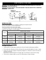
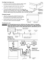
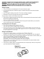
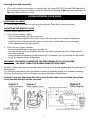
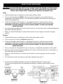
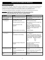
DIMPLEX IL095
INSTANT INLINE UNVENTED
WATER HEATER
Installation and User Guide
IMPORTANT:
This booklet should be left with the user after
installation and demonstration.
It should be kept in a safe place, as you may need
to refer to it for general instructions
or future maintenance
CONTENTS
Section
Introduction . . . . . . . . . . . . . . . . . . . . . . . . . . . . . . . . . . . . . . . . . . . . . . . . . . . . .
Important Safety Information . . . . . . . . . . . . . . . . . . . . . . . . . . . . . . . . . . . . . . . . .
How to install your IL095 . . . . . . . . . . . . . . . . . . . . . . . . . . . . . . . . . . . . . . . . . . . .
Commissioning your IL095 . . . . . . . . . . . . . . . . . . . . . . . . . . . . . . . . . . . . . . . . . . .
How to use your IL095 . . . . . . . . . . . . . . . . . . . . . . . . . . . . . . . . . . . . . . . . . . . . .
What to do if things go wrong (1) Self Help . . . . . . . . . . . . . . . . . . . . . . . . . . . . . .
Dimplex After Sales Service . . . . . . . . . . . . . . . . . . . . . . . . . . . . . . . . . . . . . . . . . .
Additional Accessories and Common Spare Parts . . . . . . . . . . . . . . . . . . . . . . . . . . .
What to do if things go wrong (2) Professional Service . . . . . . . . . . . . . . . . . . . . . . .
How your IL095 Works . . . . . . . . . . . . . . . . . . . . . . . . . . . . . . . . . . . . . . . . . . . . .
Guarantee and Contact Details . . . . . . . . . . . . . . . . . . . . . . . . . . . . . . . . . . . . . . . .
Page
2
2
3
7
8
9
9
9
10
11
12
INTRODUCTION
Thank you for purchasing a quality Dimplex IL095 manufactured in England.
To enjoy your new unit at its best, please take time to read this manual thoroughly to
familiarise yourself with all instructions, BEFORE beginning installation.
If you experience any difficulty with the installation or operation of your new
water heater, then please refer to the “What to do if things go wrong” section
in this manual before contacting us.
IMPORTANT SAFETY INFORMATION
•
Your IL095 has been designed for convenience, economy and safety of use, provided that it is
installed, used and maintained in good working order and in accordance with our instructions and
recommendations.
•
All wiring and installation must be supervised by a suitably qualified person.
•
THIS APPLIANCE MUST BE EARTHED.
•
The installation must be in accordance with the current edition of BS.7671 (the “IEE Wiring
Regulations”) and “Part P” of the “Building Regulations” in force at the time of installation.
Installations outside England and Wales must also conform to any local regulations in effect.
•
This appliance is intended to be permanently connected to the fixed electrical wiring of the mains
supply with its own dedicated supply.
•
This appliance must NOT be fitted where it may be subjected to freezing conditions
DO NOT switch the appliance on if you suspect it of being frozen.
Wait until you are sure it has thawed out.
•
Isolate the mains electrical and water supply before removing the front cover of the appliance.
THIS APPLIANCE IS NOT INTENDED FOR USE BY PERSONS (INCLUDING CHILDREN) WITH
REDUCED PHYSICAL, SENSORY OR MENTAL CAPABILITIES,
OR LACK OF EXPERIENCE AND KNOWLEDGE, UNLESS THEY HAVE BEEN GIVEN SUPERVISION
OR INSTRUCTION CONCERNING USE OF THE APPLIANCE
BY A PERSON RESPONSIBLE FOR THEIR SAFETY.
CHILDREN SHOULD BE SUPERVISED TO ENSURE THAT THEY
DO NOT PLAY WITH THE APPLIANCE.
2
HOW TO INSTALL YOUR IL095
WARNING: ALL WIRING AND INSTALLATION MUST BE SUPERVISED BY A SUITABLY
QUALIFIED PERSON.
WARNING: DO NOT INSTALL THIS UNIT WHERE IT MAY BE SUBJECTED TO FREEZING
CONDITIONS.
BEFORE YOU START
Check that the mains electric is capable of supplying the required current.
See the rating plate for current requirements.
Check the pressure of the main water supply.
To operate correctly, the unit requires the following running pressures.
Check the rating plate to see which applies:Dynamic Water Pressure
Model
Basin
Shower
Minimum
Maximum
Minimum
Maximum
Up to
9.5kW
10 psi (0.7 bar)
(69 kPa)
150 psi (10.3 bar)
(1035 kPa)
15 psi (1.1 bar)
(103 kPa)
150 psi (10.3 bar)
(1035 kPa)
Up to
10.8kW
15 psi (1.1 bar)
(103 kPa)
150 psi (10.3 bar)
(1035 kPa)
20 psi (1.4 bar)
(138 kPa)
150 psi (10.3 bar)
(1035 kPa)
Up to
12.0kW
20 psi (1.4 bar)
(138 kPa)
150 psi (10.3 bar)
(1035 kPa)
25 psi (1.8 bar)
(172 kPa)
150 psi (10.3 bar)
(1035 kPa)
FIXING THE UNIT TO THE WALL
Deciding the position
•
If being used in a public place, position the unit out of reach to discourage vandalism.
•
Fit the unit onto a flat piece of wall, well away from any potential splashes of water or spray.
•
Position the unit either upright or lengthways (diagram 1), whichever is most convenient for
plumbing and wiring.
Remember to keep the lengths of hot water pipe to a minimum in order to save energy.
•
If the unit is to supply a basin, you can fit it either above or below the basin.
3
Deciding the wiring route
•
You have a choice of whether to feed the electric cable
through the side or through the back of the unit.
•
If it going through the side of the unit, cut out the
plastic lug to expose the grommet (diagram 2).
•
If is going through the back of the unit, cut through the
grommet on the backplate with a sharp knife (Take Care!).
Make sure you do not remove the grommet from the backplate (diagram 3).
Feed the cable through the grommet before you fix the unit to the wall.
Fixing to the wall
•
Undo the retaining nuts and take the front cover
off the unit. Hold the backplate in position against
the wall whilst you mark the four fixing holes.
•
Drill the holes and fix the unit to the wall using the
four No.8 x 38mm wood screws supplied.
Plumbing the unit
WARNING: IF A NON RETURN VALVE IS FITTED IN THE INLET FEED TO THE UNIT,
THEN THE INSTALLATION SHOULD ALSO INCLUDE A 3.5 BAR PRESSURE
REDUCING VALVE AND A 6 BAR PRESSURE RELIEF (EXPANSION) VALVE
4
WARNING: ENSURE THAT THE MAINS WATER SUPPLY MEETS THE REQUIREMENTS
LISTED ON PAGE 3 BEFORE CONTINUING WITH INSTALLATION.
WARNING: BEFORE CONNECTING THE PIPE WORK TO THE IL095,
ENSURE THAT THE PIPE WORK IS FULLY FLUSHED OUT.
Fitting the pipes
•
The unit should be connected directly to the main cold water supply.
•
We recommend that you use Ø15mm copper or stainless steel pipe for the inlet and outlet
connections.
•
Use PTFE tape for making screw joints. Do not use a jointing compound.
•
Remember to keep the hot water pipe runs as short as possible.
In some cases, it may be worth fitting a second unit.
•
If the unit is to supply more than one basin outlet, the head should be the same at each outlet if
they are to be used at the same time.
If not, one outlet will take all the water.
•
When the pipework has been plumbed in, flush it through with water before you connect the
unit, to remove any swarf or loose particles.
Connecting the unit to the pipes
•
The inlet and outlet are clearly marked on the unit.
They each have a Ø15mm straight shank connections.
•
The unit comes with a service valve (diagram 5) which should be fitted on the inlet of the unit.
The valve can be used to turn off the water supply to the unit if it needs servicing, or to reduce
the main supply flow if it is too high.
Fitting the attachments
•
If the unit is to supply a shower, you will also need a “Dimplex Mixer Unit”.
Available in chrome/white finish and suitable for surface or concealed pipe entry (see page 9).
•
If the unit is to supply a shower, and the shower handset can reach water in a bath or basin, you
must fit a vacuum breaker to comply with Water By-laws.
Vacuum breakers are available from our sales office (see page 9).
Alternatively, use the hose-retaining feature built into the soapdish.
Because water can sometimes seep through, you should position the vacuum breaker where
dripping will not do any damage.
•
If the unit is to supply a basin, we recommend that you use spray taps, which you can get from
your local stockist (not Dimplex supplied).
5
MAKING THE ELECTRICAL CONNECTIONS
WARNING: THIS WATER HEATER MUST BE EARTHED.
The electrical installation must be in accordance with the current BS.7671 (IEE Wiring Regulations)
and “Part P” of the Building Regulations and/or local regulations
Wiring to the mains (Check the unit rating to see which applies)
•
•
•
A 40 amp 240V supply is required for the 9.5kW unit
A 45 amp 240V supply is required for the 10.8kW unit
A 50 amp 240V supply is required for the 12.0kW unit
9.5kW IL095 Wiring Conditions:
If the cable run is less than 10 metres and is surface run, 6mm² cable can be used.
A means for disconnection in all poles must be incorporated in the fixed wiring in accordance with
the wiring rules.
The isolating switch should be rated at: 40 amps or greater for the 9.5kW unit.
Wire the unit using a suitable Fuse/MCB: 40 amps Fuse/MCB for the 9.5kW unit.
12.0kW and 10.8kW IL095 Wiring Conditions:
This unit has been designed to accept 10mm² supply cable. Therefore, this is the size of cable that
should be used between the isolator switch and the unit, even if you decide to use 16mm² between
the fuse box and isolating switch. 10mm² supply cable is recommended for the 12.0kW, and for long
cable runs (greater than 10 metres) also for the 10.8kW unit.
The isolating switch should be rated at: 45 amps for the 10.8kW unit / 50 amps for the 12.0kW unit.
Wire the unit using 10mm² cable and a suitable Fuse/MCB:
45 amps Fuse/MCB for the 10.8kW unit / 50 amps Fuse/MCB for the 12.0kW unit.
If the unit is fitted in a bathroom:
9.5kW and 10.8kW IL095: A standard 45 amp cord operated isolator switch is recommended.
12.0kW IL095: A pull cord isolator switch is not available for this model. A double pole 50 amp
isolator switch is required. This must be mounted out of reach of the shower cubicle or bath.
Connecting the unit to the mains
•
Strip back the insulation on the LIVE (brown or red) and NEUTRAL (Blue or black) mains wires
about 8mm. Strip back any insulation on the EARTH (green/yellow or green) about 20mm.
•
Feed the cable through the side or rear entry grommets, as appropriate.
The outer sheath of the cable must project through the grommet (diagram 6).
If the side entry is used, this will stop water getting into the unit.
•
Connect the cables to the terminal block and earth stud (diagram 6).
•
Make sure that the live and neutral terminal block screws are tightened securely (1Nm minimum)
•
Make sure that the earth wire is wrapped around its terminal stud and into the saddle washer.
The nut should be tightened securely (2 Nm minimum).
WARNING: FAILURE TO COMPLY WITH THESE INSTRUCTIONS COULD RESULT IN
FAILURE OF THE TERMINAL BLOCK
•
Check that the Power Selector Screw) on the flow switch is set to “HI” (diagram 7).
If it is set to “LO” only one heater element will operate.
•
Fit the front cover and tighten the retaining nuts.
6
Ensuring the earth continuity
•
If the unit is fitted in a bathroom, to conform with the current BS.7671 (formally IEE regulations),
the units earth continuity conductor must be effectively connected to ALL exposed metal parts of
ALL other appliances in the room.
COMMISSIONING YOUR IL095
CHECKING FOR LEAKS
•
Let the water run through the unit for a few seconds. Check that no pipe joints leak.
ADJUSTING THE SERVICE VALVE
Turn the service valve on, then:•
If the unit is to supply a basin,
- turn on the hot water tap fully at the basin.
- adjust the service valve until the water comes out of the tap at the required temperature.
- check that the unit works correctly when the basin tap is closed and then opened again:
if not, adjust the service valve slightly.
•
If the unit is to supply a shower,
- turn the hot water tap on the mixer unit fully on.
- turn the service valve anti-clockwise until the neon light goes out, then turn it back until the
neon just comes on.
- check the water temperature at the handset and, if necessary, turn the cold tap on and adjust
to get the desired shower temperature.
WARNING: IN ORDER TO MAINTAIN THE PERFORMANCE OF YOUR SHOWER,
YOU MUST CLEAN THE SHOWER HANDSET REGULARLY.
All water contains particles of lime-scale, which build up in the shower handset and unit reducing the
performance.
It is therefore important to clean the shower handset by regularly dipping it in a suitable descaling
solution. The frequency of this will depend on water hardness and experience.
Explain to the user that when the unit is used, the hot water tap should be turned fully
on so that the unit will operate correctly.
7
HOW TO USE YOUR IL095
WARNING: DO NOT USE THE UNIT IF YOU THINK IT MAY BE FROZEN, AS THIS COULD
RESULT IN SERIOUS DAMAGE TO THE UNIT. WAIT UNTIL YOU ARE SURE
THAT IT HAS COMPLETELY THAWED OUT BEFORE YOU SWITCH ON.
Basin
•
Check that the power is switched on at the mains isolator switch.
•
Turn on the hot water tap FULLY. If you do not turn the tap on, you will find that the
temperature of the water will vary. The hot water temperature will have been set using the
service valve (diagram 5).
•
If the unit has been used recently, run the water through for a few seconds to let the
temperature settle down, we advise you DO NOT enter the water flow during this time.
WARNING: YOU MAY INITIALLY GET A SHORT BURST OF VERY HOT WATER
FROM THE UNIT.
•
If a second tap connected to the unit is also turned on, the hot water will be shared between the
two and so the flow will drop.
•
When you have finished do not switch off the power if you are going to use the unit again
shortly.
Shower
•
Check that the power is switched on at the mains local isolator switch.
•
Turn on the hot (or “flow”) tap FULLY (diagram 9).
•
If the unit has been used recently, run the water through for a few seconds to let the
temperature settle down, we advise you DO NOT enter the water flow during this time.
WARNING: YOU MAY INITIALLY GET A SHORT BURST OF VERY HOT WATER
FROM THE UNIT.
•
Turn on the cold (or “temperature”) tap, if necessary, to adjust the temperature of the water.
•
Make sure that no other outlets connected to the unit are used whilst you are in the shower, or
the water flow will drop suddenly.
•
When you have finished, do not switch off the power if you are going to use the unit again
shortly.
•
It is important to clean the shower spray plate regularly (see page 7).
•
In order for the IL095 to function correctly, the “Dimplex Mixer Kit” must be used.
The kit comes complete with full accessories including a 3 position multi-function shower
handset.
8
WHAT TO DO IF THINGS GO WRONG (1)
SELF HELP
If the unit is not working satisfactorily, make the following checks before calling out the installer.
Any one of these adjustments could restore the performance.
Symptom
Cause
What to do
Little or no water flow
The main water supply is turned
off
The main water supply is not
turned on enough
The water flow rate is too high
Turn on the main supply fully at the
stop valve
Turn on the main supply fully at the
stop valve
Adjust the service valve (see page 7)
The inlet water temperature has
dropped
Adjust the service valve (see page 7)
Cold water only
- neon light off
Water too cold
- neon light on
Water flow too low, or
temperature too high
The main water supply is too low
The hot tap is not fully open
Water goes from hot
to cold
Shower spray pattern
deteriorates
The water flow or pressure is too
low, and the thermal cut-out is
operating
A second outlet has been turned
on
The shower handset is clogged
For a shower, adjust the spray pattern
available on the multi-mode handset
Increase the supply water flow.
Make sure that the service valve is
correctly adjusted.
Adjust the service valve so that the
water is at the right temperature with
the tap fully open (see page 7)
Always turn the hot tap fully on.
Increase the supply water flow
Make sure that the service valve is
correctly adjusted
Do not use the basin whilst using the
shower
Clean the handset using a descaling
solution if required (see page 9)
DIMPLEX AFTER SALES SERVICE
We offer a technical advisory service on the telephone to installers and other customers with
problems in the field.
RING 0845 600 5111
Remember to quote the exact type of unit, as written on the front of the shower and on this leaflet.
The model and serial number are located on the bottom face of the shower.
Make a note of those numbers here, and be sure to quote them if you call for advice.
Model Number: _ _ _ _ _ _ _ _ _ _ _ _ _ Serial Number: _ _ _ _ _ _ _ _ _ _ _ _ _ _ _
Note: You may be charged for a service call if you do not have the serial number.
ADDITIONAL ACCESSORIES AND COMMON SPARE PARTS
Please Note:- The fitting of Spare Parts must be supervised by a suitably qualified person.
Chrome and White Shower Mixer Unit Complete with full accessories
Including 3 position multi-function handset
For further details, including a comprehensive list off accessories and spare parts,
contact Dimplex Customer Services 0845 6000 5111
9
WHAT TO DO IF THINGS GO WRONG (2)
PROFESSIONAL SERVICE
If the previous “Self Help” checks fail to restore the performance, you should seek professional help.
The person who installed the shower is probably the best one to investigate and correct it and is
certainly the person to contact if you have had a problem in the guarantee period.
The following additional checklist is provided for the benefit of the qualified service person.
WARNING: SWITCH OFF THE ELECTRICITY AT THE LOCAL ISOLATOR
BEFORE REMOVING THE COVER TO MAKE CHECKS
Symptom
Cause
What to do
Little or no water flows
- neon light off
The water pressure is very low
Use a pump to boost the supply from
a storage tank
Cold water only
- neon light off
The main water is connected to
the OUTLET of the unit
Reconnect the main supply to the
INLET (marked in blue)
The water pressure is too low
Use a pump to boost the supply from
a storage tank.
The thermal cut-out has
triggered
Reset it by opening the unit and
pushing the button on the cut-out
(diagram 11). Before you do this you
must remove the cause of the
problem
The flow switch is not working
Contact Dimplex
The power select screw is set to
“LO”
Change the power select screw to
"HI” (diagram 7).
One element is not working
Switch off the electricity supply and
check the resistance of the elements.
You should get the following readings.
Loading (kW) Resistance (Ohms)
9.5
12.0
10.8
10.6
12.0
9.6
The Power Supply Voltage has
dropped.
The service valve is fitted to the
OUTLET
The heater should only draw the
following currents:
40 amps for the 9.5kW model
45 amps for the 10.8kW model
50 amps for the 12.0kW model
Fit the service valve to the INLET of
the unit
There are constrictions in the
plumbing
Check the plumbing. Only use PTFE
tape for making pipe joints
Water too cold
- neon light on
Water flow too low or
temperature too high
Water goes from hot to The service valve is fitted to the
cold
OUTLET
10
Fit the service valve to the INLET of
the unit
HOW YOUR IL095 WORKS
Water comes in through the inlet, via a flow switch.
The flow switch measures how much water is passing through the unit.
If it detects more than the preset level of:2.7 litres/minute for the 9.5kW model and 3.3 litres/minute for the 10.8kW and 12.0kW models
The units heating elements are switched on. This is shown by the neon light glowing.
The water is heated instantly as it passes through the copper heat exchanger tube.
The temperature of the water coming out of the unit depends on:• The temperature of the mains water supply
• The water flow rate
• The power consumption of the unit
The temperature of the main supply can vary from 5°C in winter up to about 20°C in summer, with
an average of about 12°C. The charts below show the water temperature (°C) you can expect from
the unit, operating at 9.5/10.8/12.0Kw for the different flow rates (in litres/minute)
9.5kW IL095
Flow rate (l/m)
3.0
4.0
6.0
_
54°
43°
50°
39°
28°
4.0
5.0
6.0
_
51°
46°
44°
36°
31°
Flow rate (l/m)
5.0
6.0
7.0
Summer temp °C
54°
49°
44°
Winter temp °C
39°
34°
30°
Summer temp °C
Winter temp °C
On average
(12°C main water supply at 4 litres/minute)
an outlet temperature of 46°C will be achieved.
10.8kW IL095
Flow rate (l/m)
Summer temp °C
Winter temp °C
On average
(12°C main water supply at 5 litres/minute) an
outlet temperature of 43°C will be achieved.
12.0kW IL095
On average
(12°C main water supply at 6 litres/minute) an
outlet temperature of 41°C will be achieved.
This means that with the 12.0kW unit you can shower at 39°C with a flow rate of 5 litres/minute in
the middle of winter.
The unit includes a dual thermal cut-out (diagram 10) which is attached to
the heat exchanger tube. It will switch off the heater elements if the water
flow is reduced too much and the temperature goes above a set limit.
The first stage cut-out is cyclic and will automatically reset as the water
temperature falls. The unit will then function normally again.
The second stage cut-out when triggered needs to be reset manually inside the unit.
This cut-out will only operate in exceptional circumstances (diagram 11)
The unit can supply more than one outlet – for example, a shower and a basin, or two basins – but
water from the unit will be shared between the outlets. This is particularly important if a unit supplies
a shower and a basin, as the basin should not be used while someone is using the shower.
11
:
GUARANTEE AND CONTACT DETAILS
DIMPLEX UK LIMITED
MILLBROOK HOUSE, GRANGE DRIVE, HEDGE END, SOUTHAMPTON SO30 2DF
We offer a technical advisory service on the telephone: RING 0845 6000 5111
(A4) Leaflet No. 579-2152-17A
12