1
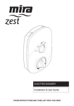
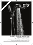
Mira Azora Thermostatic Electric Shower
Installation & User Guide
These instructions are to be left with the user
Contents
Introduction................................................................................................. 3
Important Safety Information...................................................................... 4
Pack Contents Checklist............................................................................ 6
Specifications............................................................................................. 8
Installation Requirements........................................................................... 8
Installation................................................................................................ 11
Commissioning......................................................................................... 17
User Instructions...................................................................................... 19
Fault Diagnosis......................................................................................... 21
Maintenance............................................................................................. 23
Mira Azora Spare Parts List...................................................................... 26
Accessories..............................................................................................26
Mira Energise Shower Fittings Spare Parts List....................................... 28
Dimensions............................................................................................... 29
Wiring Diagram......................................................................................... 30
Customer Services................................................................................... 31
Introduction
Thank you for purchasing a quality Mira product. To enjoy the full potential of your
new product, please take time to read this guide thoroughly. Having done so,
keep it handy for future reference.
The Mira Azora is a thermostatic electric shower with separate controls for power
selection and temperature/flow adjustment. A unique thermostatic valve stabilizes
temperature changes caused by water pressure fluctuations. These can result
from taps being turned on or off, or a toilet being flushed. An individual light indicates “ON/OFF”.
The Mira Azora comes complete with a set of Mira Energise Shower Fittings.
Mira Azora 9.8 kW
A 9.8 kW 240 V AC (9.0 kW 230 V AC) heater with Mira Azora adjustable spray
handset with four different spray actions (start, soothe, force and eco*). Supplied
complete with flexible hose, clamp bracket assembly, slide bar, supports, hose
retaining ring and soap dish. Available in a satin chrome and glass finish.
* The eco setting reduces the water flow to give economical use of water, whilst
still giving an adequate shower performance. This setting performs best with most
gravity, pumped, and mains pressure unvented systems. On electric showers and
some combination boiler systems the economy setting will have no effect, and will
give the same spray action as the start setting.
Patents and Design Registration
Design Registration:
000578463-001-002
Patents:
GB2341667, Ireland 82835
Patent Applications:
GB0612240.2, GB0415901.8, Ireland 2006/0462
If you experience any difficulty with the installation or operation of your new
shower, then please refer to the Fault Diagnosis section, before contacting
Kohler Mira Ltd. Our telephone and fax numbers can be found on the back
cover of this guide.
Important Safety Information
Installation must be carried out in accordance with these instructions, and
must be conducted by designated, qualified and competent personnel.
Warning!
Follow all warnings, cautions and instructions contained in this guide, and
on or inside the appliance.
1. Products manufactured by us are safe and risk-free, provided that they are installed, used and maintained in good working order, in accordance with our instructions and recommendations.
2. Isolate the electrical and water supplies before commencing installation. The
electricity must be turned off at the mains and the appropriate circuit fuse
removed, if applicable.
3. Mains connections are exposed when the cover is removed.
4. Refer to the wiring diagram before making any electrical connections (see
internal wiring diagram at the back of the book).
5. Make sure that any pipework that could become frozen is properly insulated.
6. Having completed the installation, make sure that the user is familiar with the
operation of the appliance.
7. Make sure that this guide is left with the user.
8. DO NOT commission this appliance if water leaks from the unit or the heater
tank pressure relief valve.
9. DO NOT fit any form of outlet control (e.g. Trigger handset) as the outlet acts
as a vent for the tank body. Only Mira recommended outlet fittings should be
used.
10. Ensure all electrical connections are tight, to prevent overheating.
11. Warning! DO NOT operate this appliance if it is frozen. Allow the appliance to
thaw before using. The shower unit must not be fitted where it may be exposed
to freezing conditions.
12. This product is not suitable for areas with high humidity (i.e. steam rooms).
Please consult your installer.
13. THIS APPLIANCE MUST BE EARTHED. ENSURE SUPPLEMENTARY
BONDING COMPLIES WITH THE “REQUIREMENTS FOR ELECTRICAL
INSTALLATIONS”.
In accordance with the current edition of “The Plugs and Sockets etc. (Safety)
Regulations” in force at the time of installation, this Mira Escape is intended to
be permanently connected to the fixed electrical wiring of the mains system.
Caution!
1. Read all of these instructions and retain this guide for later use.
2. The electrical installation must comply to “BS 7671 - Requirements for Electrical
Installations”, commonly referred to as the IEE Wiring Regulations - Part 7, or
any particular regulations and practices, specified by the local electricity supply
company.
3. The plumbing installation must comply with the requirements of UK Water
Regulations/Bye-laws (Scotland), Building Regulations or any particular
regulations and practices, specified by the local water company or water
undertakers.
4. Make sure that you fully understand how to operate this shower and make sure
that it is properly maintained in accordance with the instructions given in this
manual.
5. Anyone who may have difficulty understanding or operating the controls of any
shower should be attended whilst showering. Particular consideration should
be given to:
The young, the elderly, the infirm, the disabled, anyone who suffers from
a medical condition that can result in temporary incapacity (e.g. epilepsy
or blackouts), anyone inexperienced in the correct operation of the
controls.
6. Sunburn or skin conditions can increase your sensitivity to hot water. Make sure
that you set the shower to a cooler temperature.
7. If any of the following conditions occur, isolate the electricity and water supplies
and refer to ”Customer Services”, in the back page of this guide.
• If the cover is not correctly fitted and water has entered the
appliance case.
• If the case is damaged.
• If the appliance begins to make an odd noise, smell or smoke.
• If the appliance shows signs of a distinct change in performance,
indicating a need for maintenance.
• DO NOT operate if water leaks from the appliance.
8. When this appliance has reached the end of its serviceable life, it should be
disposed of in a safe manner, in accordance with current local authority recycling,
or waste disposal policy.
Pack Contents Checklist
Mira Azora
Tick the appropriate boxes to familiarise yourself with the part names and to
confirm that the parts are included.
1 x Olive
1 x Compression Nut
3 x Fixing Screws
3 x Wall Plugs
1 x Mira Azora
Documentation
1 x Installation and User Guide
1 x Installation Template
1 x Installer Checklist
1 x Guarantee Card
Mira Energise Electric Shower Fittings
Tick the appropriate boxes to familiarise yourself with the part names and to confirm that the parts are included.
2 x Slide Bar Ends
2 x Wall Plugs
2 x End Supports
1 x Slide Bar
1 x Handset
1 x Flexible Hose
1 x Clamp Bracket
Assembly
2 x Hose Seals
1 x Soap Dish
1 x Hose Retaining
Ring
2 x Fixing Screws
2 x End Plugs
Documentation
1 x Installation and User Guide
Specifications
1. Plumbing
Minimum maintained inlet pressure 70 kPa (0.7 bar).
100 kPa (1.0 bar) recommended for satisfactory operation.
Maximum static inlet pressure 1000 kPa (10 bar).
Minimum static pressure 20 kPa (0.2 bar) to keep the inlet valve closed.
2. Electrical
The Mira Azora 9.8 kW requires a 45 Amp fuse.
The terminal block will accept cable up to 16 mm2 .
3. Standards and Approvals
The Mira Azora complies with all relevant directives for CE marking.
Installation Requirements
1. Plumbing
The appliance is designed to operate with a minimum maintained inlet
pressure of 0.7 bar up to a maximum static inlet pressure of 10 bar.
When installed in very hard water areas (above 200 ppm temporary
hardness) your installer may advise the installation of a water treatment
device, to reduce the effects of limescale formation. Your local water
company will be able to advise the hardness of water in your area.
It is recommended that a non-restrictive (free flowing) isolating valve
is fitted in the cold water supply pipe to allow the complete maintenance
of the appliance. Do not use a valve with a loose washer plate (jumper)
as this can lead to a build up of static pressures.
The appliance is suitable for installation within the shower area. It is fitted
with a pressure relief device and must be positioned over a water
catchment area with the controls at a convenient height for all users.
The appliance must be fitted on to a finished flat and even wall surface
(this wall surface should be tiled or waterproofed). Do not fit the
appliance to the wall and tile up to the case. For safety requirements, an
air gap must be left behind the appliance.
Avoid layouts where the shower hose will be sharply kinked. This may
reduce the life of the hose.
A Hose Retaining Ring is supplied to prevent the handset from dropping below the spill-over level of the bath or shower tray, which
could lead to contamination from back-siphoning. The supplied Hose
Retaining Ring should meet the majority of user requirements for
shower installations with flexible outlet fittings. However, there will be
occasions when it will not provide a suitable solution. In these instances
an outlet double checkvalve, e.g. a Mira DCV-H, must be fitted. This
will increase the required supply pressure typically by 0.1 bar (see section
“Accessories”).
Supply pipework must be flushed to clear debris before connecting to
the appliance.
To avoid damage to the case when soldered fittings are used, pre-solder
the pipework and fittings before connecting them to the inlet connector
assembly. Refrain from applying excessive force when making any
connections. Always provide mechanical support when making the
plumbing connections.
The appliance is fitted with a brass inlet compression assembly for
connecting to a 15mm supply pipe from the top, bottom or back. Double
checkvalves, if fitted in the inlet supply to the appliance, can cause a
pressure build-up, which could exceed the maximum static inlet pressure and damage the appliance.
Minimum
200mm from
ceiling
Convenient height
for all the family
Fixed to finished
wall surface
Hose Retaining Ring
Isolating Valve
25 mm Min
Avoid Sharp Kinks
Bath
Shower Tray
2. Electrical
In a domestic installation, the rating of the electricity supplier’s fuse and
the consumer unit must be adequate for the additional demand. All Mira
electric showers are high power units, it is essential to contact your
electricity supplier to ensure that the supply is adequate for the product.
Voltage drop due to local heavy demand will reduce the shower’s
performance.
The appliance must be earthed by connecting the supply-cable earth
conductor to the earth terminal.
Supplementary bonding: Within the bathroom or shower room, all accessible conductive parts of electrical equipment and extraneous conductive parts (metal parts) that are likely to introduce earth potential,
must be electrically bonded to earth using a minimum cable size of
4.0mm2 if the cable is not mechanically protected, (2.5 mm2 if
mechanically protected).
The minimum cable size (cross-sectional area) required should be in accordance with BS 7671.
As a guide only, and in accordance with BS 7671 we recommend close
circuit protection: i.e. 9.8 kW = 45 Amp
A separate, permanently connected supply must be taken from the
consumer unit to the appliance through a double-pole switch, which has
at least 3 mm of contact separation. The switch can be a ceiling mounted
pullcord type within the shower room, or a wall mounted switch in an
adjacent room.
DO NOT twist the individual cable cores of either the live or neutral
conductors, as this will prevent them from entering the terminal block.
DO NOT exert strain on the terminal block. Ensure that the electrical
connections are tightly screwed down.
DO NOT turn-on the electrical supply until the plumbing has been
completed.
It is strongly recommended that a 30 mA Residual Current Device (RCD)
is included in the electrical circuit. This may be part of the consumer unit
or a separate unit.
10
Consumer Unit
Double-pole
Isolating Switch
Installation
1 Installation of Mira Azora
Warning! Turn off the electrical and water supplies before proceeding with the
installation of the Mira Azora. The electricity must be turned off at the mains
and the appropriate circuit fuse removed, if applicable.
Note! An installation template is supplied to help you install the Mira Azora.
Cover Retaining
Screw
Remove the three cover retaining
screws and the cover.
Caution! Handle glass cover assembly
with care.
Cover
11
Determine the direction of the inlet
water supply: top (falling), bottom
(rising), or back inlet .
Note! Make sure that the back inlet
does not go directly back into the
wall. Use a soldered elbow.
Swivel the inlet connector assembly
to suit. Remove the inlet blanking
cap. Avoid trapping the green earth
bonding wire.
Before fitting the Cover, make sure that the appropriate cutouts have been
removed to suit the supply entering the product.
Thoroughly flush the mains-fed cold water supply pipe. The supply
must be clean and free from debris before connecting the appliance.
To flush the pipework, turn on the water supply and drain a minimum of 10
litres (2 gallons) of water into a bucket or catchment area. Turn off the water
supply.
An installation template is supplied to help you install the Mira Azora.
Put the installation template on the wall and mark through the positions of the
fixing holes. Ensure the position of these holes do not come in line with any
buried cables or pipework. Make sure that sufficient electrical supply cable is
available for connection to the terminal block.
Drill and plug the top two fixing holes. Secure the appliance to the wall with
the screws provided. Drill the bottom fixing hole with the product in place.
Alternative fixings (not supplied) may be necessary for some wall structures.
Avoid drilling into any supply cable/pipe.
Install the mains-fed cold water
supply pipe. Do not overtighten.
12
Feed cable into Case. Fit Earth
sleeve (not supplied) and then
strip insulation.
Do not twist cable cores.
L = BROWN
E = GREEN/YELLOW
Firmly connect the conductors. Do
not exert strain on the terminal
block.
N = BLUE
Cover Retaining
Screw
Refit the Cover, making sure it is
correctly located. Do not overtighten
screws.
Caution! Handle glass cover
assembly with care.
Do not use alternative screws to
secure the Cover. This can cause
internal damage to the appliance.
Do not seal around the back of
appliance.
Cover
When fitting the Cover, position
the controls to correspond with the
internal drive features as shown.
13
Holes For Cover
Retaining Screws
Fixing Screw
Terminal
Block
Heater Tank
Electrical
Supply Cable
Inlet Connector
Assembly
Cold Water Supply
Pipe (Bottom Entry)
14
2 Installation of Shower Fittings
Decide on a suitable position for the slide bar avoiding buried cables and
pipes.
Drill the two 7.0 mm fixing holes for the slidebar at 600 mm centres and insert
the wall plugs.
Assemble the clamp bracket components. Push the plastic slidebar ends into
the slidebar.
Push the slidebar through the clamp bracket assembly, soapdish and hose
retaining ring.
Fit the bottom end support loosely to the wall. This will make aligning the top
support easier. Insert the fixing screw into the countersunk hole of the plastic
slide bar end and through the slidebar support.
Place the screw through the top end support and fully tighten. Fully tighten
the bottom end support.
Fit the end support caps over the slidebar end supports.
Screw the hose onto the handset and the outlet of the shower (Make sure the
hose seals are fitted). Do not overtighten.
Place the handset into the slidebar clamp bracket.
Note! The clamp bracket is tapered. The handset will only fit properly from
one direction. If necessary turn the end of the clamp bracket until the handset
will fit.
If the clamp bracket pivots downwards under the weight of the handset
the central securing screw in the bracket will require tightening to hold the
handset in position.
15
End Support
Slidebar End
Fixing Screw
Handset
Clamp Bracket Assembly
600 mm
Slidebar
Soap Dish
Hose Retaining Ring
End Support Cap
16
Commissioning
If you are unsure how an electric shower works, please read through the section
“User Instructions” before continuing.
1.
2.
Electrical supply is
turned off at the mains.
4.
3.
Turn control to full cold.
5.
6.
Set control to ‘I’.
Check for water leaks.
7.
Turn the water supply fully
on.
8.
Switch on electrical supply.
9.
0 - 5 Secs
Water will be at full force
Press the ‘Start/Stop’ button. and at a cool temperature.
10.
11.
12.
Turn the control slowly.
Temperature remains cool
and flow is reduced
0 - 10 Secs
Turn control to full cold.
Set control to ‘II’.
17
The temperature will rise slightly.
13.
14.
5 - 10 Secs
Set control to ‘III’.
15.
The temperature will rise further.
16.
Adjust temperature as
required. Flow rate will adjust
automatically.
17.
Press STOP and isolate power.
18.
0 - 5 Secs
The shower will purge from its tank
for a few seconds.
Residual water may drain over a few minutes.
Note! A slight hissing sound may be heard from the appliance during operation.
High mains water pressure and high shower temperatures will affect the tone.
This is quite normal in use.
18
User Instructions
Read the section “Important Safety Information” first.
1.
3.
2.
Switch on electrical supply.
Set to desired position.
5.
Press the ‘Start/Stop’ button.
4.
Check water temperature before
entering shower.
Allow 10 - 15 seconds for any temperature adjustments to reach the handset.
7.
6.
Residual water may drain over a
few minutes.
Press STOP button. Shower will continue to
run for a few seconds before stopping.
Note! At the end of every shower make sure that the shower head points into the
catchment area. A small amount of water may be retained in the shower handset
after the shower has been turned off. This may drain over a few minutes.
19
Spray Action
The handset spray head has four different spray actions:- Eco, Start, Soothe and
Force. The handset operation is described below.
1. Eco
To access the eco setting, turn
the spray plate fully clockwise.
Water will flow from the
outer set of holes at a reduced flow rate.
2.
Start
To access the start setting turn the spray plate anticlockwise until it ‘clicks’ (one click from the eco setting). Water will flow from the outer set of holes.
3. Soothe
To access the soothe setting
turn the spray plate
anticlockwise until it ‘clicks’ (two
clicks from the eco setting).
Water will flow from the large
diameter holes.
4.
Force
To access the force setting turn
the spray plate anticlockwise
until it ‘clicks’ (three clicks from the eco setting). Water will flow from the inner set of holes.
20
Fault Diagnosis
The trouble shooting information tabled below gives details on probable causes and
remedies should difficulties be encountered whilst the shower is in operation.
Warning! There are no user serviceable components beneath the cover of the appliance.
ONLY A COMPETENT TRADESPERSON SHOULD REMOVE THE FRONT COVER!
Symptom
Appliance fails
to operate.
Shower cycles
from hot to
cold.
Unable to
select a cool
enough shower.
Power
Light
Heater
Setting
OFF
Any
Electrical supply isolated at
double pole switch.
OFF
Any
Fuse blown or MCB/RCD
tripped, indicating possible
electrical fault.
Switch on electrical supply via
the pullcord or wall mounted
switch.
Renew the fuse or reset the
MCB/RCD. If fault persists,
contact your installer.
ON
II/III
Handset blocked.
Remove and clean.
ON
II/III
Water pressure below
minimum required for
appliance operation.
Make sure incoming mains
water stopcock and/or appliance
isolating valve is fully turned on.
ON
II/III
Temperature dial or Heater
setting too high.
Turn the Heater Control to II
setting or turn the Temperature
Control until a cooler
temperature is achieved.
ON
II/III
Thermostatic mechanism is
faulty or damaged.
Replace.
ON
III
Due to the rise in mains
water supply temperature,
the Heater setting may be
too high.
Turn the Heater Control to II
and adjust the Temperature
control until a suitable
temperature is achieved.
Probable Cause
Possible Remedy
I/II/III
All of the following remedies must only be performed by a Competent Tradesperson
Handset
dripping.
OFF
Any
Insufficient Water supply
pressure for shut off.
The minimum static pressure
to ensure shut off and prevent
dripping is 0.2 bar.
Note: If other appliances are
operating, static pressure may
drop below 0.2 bar. Contact
local water company. Renew
the Flow Valve.
OFF
Any
Inlet Valve faulty.
Replace.
21
Symptom
Power
Light
Low or No
flow
Operation of
Temperature
Control has
little or no
effect on water
temperature.
Heater
Setting
Probable Cause
Possible Remedy
Low/Medium/
High
ON
Any
Water supply pipework or
Flush supply pipe. Clean Inlet
inlet filter restricted by a
Filter.
blockage or partial blockage.
ON
Any
Insufficient water supply
pressure/flow for operation.
Contact local water company.
Supply pressure must be a
minimum of 0.7 bar.
Note: If other appliances are
operating, pressure may drop
below 0.7 bar.
ON
Any
Other outlets (e.g. toilet,
garden hose, washing
machine, etc.) drawing
water while the shower is
being used.
Turn off other appliances whilst
shower is in use.
ON
Any
Handset blocked.
Remove and clean.
ON
Any
Cover not fitted correctly
causing Start/Stop
button not to operate.
Check Cover is cut and fitted
correctly. Check services
(electrical or plumbing) are not
interfering with location of Cover.
ON
Any
Inlet Valve faulty.
Replace.
ON
Any
Heater Tank excessively
scaled.
Replace. In hard water areas
consider the use of a water
softener.
ON
II/III
Handset or Inlet Filter
blocked.
Remove and clean.
ON
II/III
Inlet Valve faulty.
Replace.
ON
II/III
Heater Tank failure.
Replace.
ON
II/III
Microswitch failure.
Replace.
22
Symptom
Power
Light
Heater
Setting
Probable Cause
Possible Remedy
Low/Medium/
High
No change in
temperature
between Low/
Medium/High
setting.
ON
Any
Insufficient mains water
pressure.
Contact local water company.
ON
Any
Possible failure of Flow
Valve, Microswitch, or
Heater Tank.
Use a suitable continuity
device to check the continuity
of the Microswitch or Heater
Tank and replace parts
as necessary.
Water will not
turn off.
ON
Any
Inlet Valve, Solenoid, or
Start/Stop switch faulty.
Replace as necessary.
ON
Any
Supply pressure below
0.2 bar.
Contact local water company.
Check mains water static
pressure.
ON
II/III
Insufficient Water supply.
Contact local water
company.
ON
II/III
Possible failure of the
Microswitch or thermal
switch.
Use a suitable continuity
device to check the continuity
of the Microswitch or Heater
Tank and replace parts as
necessary.
ON
II/III
Heater Tank failure.
Replace.
Appliance fails
to produce hot
water when set
on Medium/
High Heater
Setting.
Maintenance
Handset - Cleaning
Clean with mild washing up detergent or
soap solution. Wipe dry with a soft cloth.
Poor shower performance can be
avoided by cleaning the spray plate.
Use thumb or soft cloth to wipe rubber
nozzles. The handset must be descaled
regularly.
23
Inlet Filter - Cleaning/Renewing
Cover Retaining Screw
Read the section “Important Safety Information” first
Make sure that the electrical supply
is turned off at the mains and that
the water supply is fully turned off.
Remove the three screws and
the cover.
Caution! Handle glass cover
assembly with care.
Cover
Hold a wrench across the flats of
the metal connector. Unscrew
the filter using another wrench as
shown. Clean or renew the Filter
as necessary. Refit in reverse order
making sure the Filter is screwed
fully home.
Do not overtighten. Make sure
plumbing connections are sealed
before restoring electricity supply.
Refit the Cover making sure
it is correctly located. Do not
overtighten the screws.
24
Filter
Spare Parts List
25
Mira Azora Spare Parts List
405.58
406.27
416.38
416.41
416.48
416.51
872.01
872.28
1563.519
1563.533
1563.534
1563.537
1563.538
1563.539
1563.540
1563.551
1634.009
1634.015
1634.026
Inlet Connector Assembly
Inlet Filter (with ‘O’ seal fitted)
Clamp Bracket (Inlet)
Thermal Switch
Latching Switch
Solenoid Coil
Microswitch N/O - 2 pin
Microswitch C/O - 3 pin
Terminal Block Assembly
Thermostatic Valve/Heater Tank 9.8 kW 240 V AC
Outlet Connector Assembly
Temperature Control Belt Thermostatic
Temperature Cam & Pulley
Switching Assembly
Inlet Valve Assembly
Component Pack - chrome - components identified ‘B’
Cover Assembly
Power On LED Assembly
Screw Pack - components identified ‘A’
Accessories
DCV-H: An outlet double check valve, designed to prevent
the backflow or backsiphonage of potentially contaminated
water, through shower controls which are fitted with a
flexible hose as part of the outlet shower fitting. Available
as an optional accessory from your Mira Showers stockists.
26
Mira Azora Spare Parts Diagram
B
A
A
A
B
B
416.41
1563.519
1563.539
872.01
B
1563.533
A
1563.538
A
A
872.28
1563.540
406.27
416.48
A
A
416.51
1563.507
1563.537
B
405.58
416.38
A
1563.534
A
1634.015
1634.009
27
Mira Energise Shower Fittings Spare Parts List
126.65
Slidebar Ends
449.02
Slidebar
449.01
Clamp Bracket
Assembly
449.04
Soap Dish
450.36
Spray Plate
Pack
632.73
Hose Seal (x2)
1563.593
Adjuster
Ring
449.05
Hose
1563.594
Hose Retaining
Ring
449.03
Slidebar Wall Fixing
Assembly
28
1563.592
Handset
Dimensions
77 mm
100 mm
233 mm
367 mm
69 mm
600 mm
660 mm
29
Wiring Diagram
Thermal Cutout
Dual Disc
L
Pressure/Power
Selector Switch
Solenoid
Valve
Power On
L.E.D.
Load
START/STOP
N
E
Tank Connection
Inlet Connector
Internal Wiring Diagram
30
Customer Services
Guarantee of Quality
Spare Parts
Mira Showers guarantee your product against any defect
in materials or workmanship for the period shown in the
Guarantee Registration Document included with your
shower.
Alternatively, to confirm the applicable guarantee period
please contact Customer Services.
To validate the guarantee, please return your completed
registration card.
Within the guarantee period we will resolve defects, free
of charge, by repairing or replacing parts or modules as
we may choose.
To be free of charge, service work must only be
undertaken by Mira Showers or our approved agents in
Northern Ireland and Republic of Ireland.
Service under this guarantee does not affect the expiry
date. The guarantee on any exchanged parts or product
ends when the normal product guarantee period expires.
Not covered by this guarantee:
Damage or defects arising from incorrect installation,
improper use or lack of maintenance, including build-up
of limescale.
Damage or defects if the product is taken apart, repaired
or modified by any person not authorised by Mira
Showers or our approved agents.
This guarantee is in addition to your statutory and other
legal rights.
We maintain an extensive stock of spares, and aim to
provide support throughout the product’s expected life.
Spares can be purchased from approved stockists or
merchants (locations on request) or direct from Customer
Services.
Spares direct will normally be despatched within
two working days. Payment can be made by Visa or
Mastercard at the time of ordering. Should payment by
cheque be preferred a pro-forma invoice will be sent.
Note! In the interests of safety, spares requiring exposure
to mains voltages can only be sent to competent persons.
Service
Our Service Force is available to provide a quality service
at a reasonable cost. You will have the assurance of a
Mira trained engineer/agent, genuine Mira spares – and a
12 month guarantee on the repair.
Payment should be made directly to the Service
Engineer/Agent, using Visa, Mastercard or a cheque
supported by a banker’s card.
To contact us
Before using your shower
Please take the time to read and understand the
operating and safety instructions detailed in this manual.
What to do if something goes wrong
If when you first use your shower it doesn’t function
correctly, first contact your installer to check that
installation and commissioning are satisfactory and in
accordance with the instructions in this manual. We are
on-hand to offer you or your installer any advice you may
need.
Should this not resolve the difficulty, simply contact our
Customer Services who will give every assistance, and if
necessary arrange for our service engineer to visit.
If later the performance of your shower declines, consult
this manual to see whether simple home maintenance
is required. Please call our Customer Services to talk
the difficulty through, request service under guarantee
if applicable, or take advantage of our comprehensive
After-Sales service.
As part of our quality and training programme calls may
be recorded or monitored.
Our Customer Services Team is comprehensively trained
to provide every assistance you may need: help and
advice, spare parts or a service visit.
England, Scotland & Wales
Mira Showers Customer Services
Telephone: 0870 241 0888
8:30 am to 5:00 pm Working days (4:30 pm Friday)
8:30 am to 12:30 pm Saturday
E-mail:
[email protected]
Fax:
01242 282595
By Post:
Cromwell Road
Cheltenham
Gloucestershire
GL52 5EP
Northern Ireland
Wm H Leech & Son Ltd
Telephone: 028 9044 9257 – Mon to Fri 9 am-5pm
Fax:
028 9044 9234 – 24 hours
Post:
Maryland Industrial Estate
Ballygowan Road
Moneyreagh, Co Down
BT23 6BL
Republic of Ireland
Modern Plant Ltd
Telephone: 01 4591344 – Mon to Fri 9am to 5pm
Fax:
Dublin 01 4592329 – 24 hours
E-mail:
[email protected]
Post:
Otter House
Naas Road
Clondalkin
Dublin 22
31
Mira Showers
Kohler Mira Ltd
Cromwell Road,
Cheltenham GL52 5EP.
Mira is a registered trade mark of
Kohler Mira Limited.
The company reserves the right to alter
product specifications without notice.
www.mirashowers.com
1062243-W2-A (J95L)
© Kohler Mira Limited, September 2006
32