1
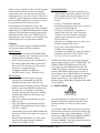
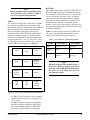
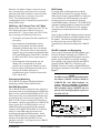
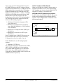
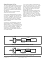
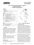
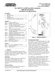
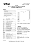
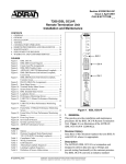
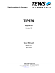
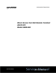
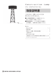
Section 61102040L3-5A
Issue 1, June 2000
CLEI Code #5SC5T5XF_ _
SLC-5 U-BR1TE III With DDS Loopbacks
ISDN 2B1Q Interface
Installation and Maintenance
CONTENTS
1. GENERAL ..................................................................... 1
2. INSTALLATION .......................................................... 2
3. TESTING ....................................................................... 8
4. MAINTENANCE ........................................................ 12
5. WARRANTY AND CUSTOMER SERVICE ............ 12
FIGURES
Figure 1. ADTRAN SLC-5 U-BR1TE III ........................ 1
Figure 2. SLC-5 U-BR1TE Slot Placement Examples .... 3
Figure 3. Backplane Pin Assignments .............................. 4
Figure 4. SW1 and SW2 Labeling .................................... 4
Figure 5. Position Switch Settings at Network
Locations ........................................................... 6
Figure 6. U-BR1TE III IDSL/DDS Circuit Diagram ....... 6
Figure 7. IDSL/DDS Loopback Response ....................... 9
Figure 8. ADTRAN U-BR1TE Bidirectional
Loopback ......................................................... 10
Figure 9. IDSL/DDS Remote End Initiated
Loopback, Local Loop .................................... 11
Figure 10. IDSL/DDS Remote End Initiated
Loopback, Customer Loop .............................. 11
Figure 11. IDSL/DDS Trouble Codes .............................. 12
TABLES
Table 1. SLC-2000 CIT Provisioning Options .................. 3
Table 2. Internal Switch Option Settings ........................... 5
Table 3. Rotary Switch Legend ......................................... 7
Table 4. Front Panel LED Indication ................................. 7
1. GENERAL
This practice provides installation and maintenance
information for the ADTRAN SLC-5 U-BR1TE III
With DDS Loopback (U-BR1TE III). Figure 1 is an
illustration of the unit. The U-BR1TE III (P/N
1102040L3) is a direct replacement and fully
compatible with the previous ADTRAN SLC-5
U-BR1TEs, including the 1100040L1, 1100040L3,
1102040L2, and the 1102040L1.
ISDN/DDS
The U-BR1TE III employs features for both ISDN and
DDS transport. ISDN comprises the major functionality
and is described in this section. A description of DDS
functionality is located in Section 3.
Revision History
This is the initial release of this document. Future
revisions will be described in this subsection.
61102040L3-5A
1 2
3 4
U-BR1TE III
DDS
1102040L3
ACT
LP
SW1
SW3
SW2
CR
B
2
2
B
1
1
2
Figure 1. ADTRAN SLC-5 U-BR1TE III
Functional Description
The U-BR1TE III is a channel unit for use in the
AT&T® SLC Series 5 and Series 2000 Digital Loop
Carrier Systems. The U-BR1TE III allows the
deployment of Basic Rate ISDN to locations whose
telephone services are provided from these DLC
systems. It can be used in a SLC-5 Central Office
Terminal deployed as Feature Package C , and SLC-5
Remote Terminals deployed as Feature Package C
without Autocut and Feature Package B. The
U-BR1TE III will also operate in SLC-2000 COTs and
RTs when deployed as SLC Mode 1. Clear Channel
capability (B8ZS) is not required of the T1 facility if
zero byte substitution is enabled on the U-BR1TE III.
The U-BR1TE III plugs into a single physical slot of
the channel bank. Three time slots are required for
transport of 2B+D information. Block error rate
performance over the T1 facility is monitored and is
available to the network.
The SLC-5 U-BR1TE III incorporates a feature that
allows for detection of ISDN capable and non-ISDN
capable SLC-5 Bank Controller Units. In addition, the
unit will facilitate communications to the non-ISDN
capable BCU for the time slots associated with the
adjacent physical slot, eliminating the need for the
NULL Channel Unit, P/N 1200102L1, in the nonISDN SLC-5 terminals.
Trademarks: Any brand names and product names included in this document are trademarks, registered
Issue 1
trademarks, or tradeSection
names of 61102040L3-5,
their respective holders.
1
Earlier versions of the SLC-5 BCU will not recognize
an ISDN channel unit ID, and will not assign the
required time slots of the next physical position for
2B+D operation. For previous versions of the SLC-5
U-BR1TE, a NULL channel unit, which communicated
to the non-ISDN capable BCU, is required to reserve
the associated time slots for 2B+D service.
By automatically determining the version and
requesting the necessary time slots for the non-ISDN
capable BCUs, the U-BR1TE III eliminates the confusion
regarding 2B+D deployment, and the requirement of
deploying the NULL cards. The U-BR1TE III will
operate properly when a NULL card is installed in the
adjacent physical, as in a replacement situation.
Features
U-BR1TE III features support both ISDN and DDS,
plus features common to both as listed here:
ISDN Features:
• Provides for the transport of ISDN Basic Rate
2B+D information over T1 facilities in the 3-DS0
format specified in TR-NWT-000397.
• NULL card not required with non-ISDN BCUs.
• B1 or B2 loopback addressability at the front
panel for the NT1 and up to six devices in the
Network-to-Customer direction.
• Compatible with MLT 3.0/ISDN per
TR-NWT-000397, Issue 3, December 1993.
DDS Features:
• Perform bidirectional loopback (loop and
network) when commanded into DS0 DP
loopback from the network direction only.
• Loopback release in response to TIPs per TR62310.
• Remap all subsequent DS0 DP loopback codes
into respective eoc loopbacks to loop back
respective downstream U-Repeaters, TRISDN
elements, and U-BR1TEs when optioned for
1B+D, or 2B+D.
• Pass OCU loopback code through to loop the
IDSL OCU-R.
• Pass CSU loopback code through to loop the
CSU/DSU and simultaneously send a remap to
the NT1 eoc address.
• Transmit Mux-Out-of-Sync (MOS) trouble code
upstream for IDSL loss of signal, loss of sync, or
open loop.
• Returns Abnormal Station Code (ASC) to the
network in B1 during loopback conditions
initiated by the IDSL OCU-R.
2
Common Features:
• ISDN 2B+D interface which meets all Layer 1
requirements as specified in ANSI T1.601-1992.
• 18 kft nominal range on mixed gauge wire (42
dB @ 40 kHz loop loss, 1300 Ω DC resistance
design).
• All Layer 1 maintenance functions.
• Performance monitoring of the Layer 1 facility as
specified in TR-NWT-000397.
• A distinctive metallic DC test signature to
identify either Line Unit Loop Termination
(LULT) or Line Unit Network Termination
(LUNT) mode of operation as specified in
TR-NWT-000397.
• DS0 logic level transmit and receive data access
through a front panel RJ-45 jack.
• Loop, carrier, and synchronization status
available at the front panel.
• Compatible with AT&T SLC-2000, SLC Mode 1.
• Compliant with TR-TSY-829, TR-TSY-1089,
FCC Part 15, Class A, and UL 1459.
ADTRAN has obtained the necessary licenses that
grant the right to develop a SLC-5 U-BR1TE III. The
ADTRAN U-BR1TE III replaces the AT&T AU92
(COT) and AU93 (RT) BRITE channel units. The
U-BR1TE III (TR397 compliant) will not function
with the AT&T BRITE channel units across the T1
carrier facilities. The U-BR1TE III must be terminated
across the T1 carrier facilities with another channel
unit that meets TR 397. The U-BR1TE III will
function with any ISDN 2B1Q U-interface that is ANSI
T1.601 compliant.
2. INSTALLATION
C A U T I O N !
SUBJECT TO ELECTROSTATIC DAMAGE
OR DECREASE IN RELIABILITY.
HANDLING PRECAUTIONS REQUIRED.
After unpacking the unit, inspect it for damage. If
damage is noted, file a claim with the carrier, then
contact ADTRAN. See Warranty and Customer
Service.
To install the U-BR1TE III, hold the unit by the front
panel and insert it into the assigned slot until the edge
connector is firmly seated in the backplane. The ACT
LED on the U-BR1TE III should illuminate GREEN.
The CR and LP LEDs will flash GREEN then
illuminate AMBER. At this point, push the unit latch
upward until it locks into place.
Section 61102040L3-5, Issue 1
61102040L3-5A
NOTE
During installation rotary switch SW3 can be
in any position except 7 (LPBK). LPBK is
reserved for special testing functions.
SLC-5
The U-BR1TE III plugs into a single SLC-5 channel
slot. Because two time slots are assigned to each
physical slot in a SLC-5 channel bank, and a U-BR1TE
III provisioned as 2B+D requires three time slots,
there are restrictions that apply to the physical
placement of the U-BR1TE III in the channel bank.
Each SLC-5 digroup consists of 12 physical slots,
which can be divided into four groups of three slots
each (physical slots 1-3, 4-6, 7-9, and 10-12). These
tri-slot groups are used to define the slot restrictions
for the U-BR1TE III as follows (see Figure 2):
I
II
III
IV
2B+D
2B+D
1
2
3
2B+D
Empty
Available
for Other
Services
4
5
6
Available
for Other
Services
2B+D
Empty
7
8
9
1B+D
OR
2B
1B+D
OR
2B
Available
for Other
Services
11
12
Empty
SLC 2000
The U-BR1TE III operates in all SLC-2000 COT and
RT shelves and can be used in combination with any
mix of other SLC-2000 channel units. Currently, the
unit will not operate in a mode 2 shelf. All option
information for SLC-2000 channel units is entered
using the SLC-2000 Craft Interface Terminal (CIT)
and stored in the controller’s nonvolatile system
memory. Once a slot is provisioned, it does not need
to be provisioned again unless a different channel unit
is installed in that slot.
Table 1 lists the options to set for the U-BR1TE III.
The service provisioned should match the switch
settings or the unit may not operate properly.
Table 1. SLC-2000 CIT Provisioning Options
Option
SLC-2000 COT
SLC-2000 RT
CLEI
5SC1JE
5SC1HE
Function
Code
BRI
BRI
Service
2B+D, B1+D,
B2+D, D
2B+D, B1+D,
B2+D, D
NOTE
When the U-BR1TE III is optioned for B1 or
B2, the SLC-2000 slot must be provisioned
for D only. If the U-BR1TE III is optioned for
2B, then the SLC-2000 slot must be
provisioned for B1+D.
13
Figure 2. SLC-5 U-BR1TE Slot Placement Examples
• A U-BR1TE III provisioned as 2B+D cannot be
installed in the last slot of a tri-slot group (slots
3, 6, 9, or 12).
• A U-BR1TE III provisioned as anything other
than 2B+D cannot be installed in the physical
slot to the immediate right of a U-BR1TE III
provisioned as 2B+D within a tri-slot group.
61102040L3-5A
Section 61102040L3-5, Issue 1
3
Physical Requirements
The U-BR1TE III occupies one physical slot in the
SLC-5 or SLC-2000 channel bank. The backplane pin
assignments are illustrated in Figure 3.
+5R
23
48
NSYNC
+5R
22
47
CTPCM
GND
21
46
CRPCM
GND
20
45
NPE
GND
19
44
4 MHz
DCU
18
43
NQ
GND
17
42
NP0
NSR
16
41
MSG
DCU
15
40
NMP
8 KHz
14
39
NMQ
GND
13
38
64 KHz
12
37
Option Switch Settings
See Figure 1 and Figure 4 for SW1 and SW2 location.
The options for SW1 and SW2 are described in Table 2.
Figure 5 displays the position switch settings at ISDN
network locations. Figure 6 displays the position
switch settings at IDSL/DDS network locations.
LULT
(RT)
SW2
LUNT
(COT)
LULT
(RT)
O
N
36
CHTR
10
35
CHTT
9
34
LPTR
8
33
LPTT
7
32
RING *
6
31
TIP *
5
30
4
29
3
28
RG
2
27
FRGRD
1
26
O1 2 3 4
N
2
TANDEM
ADJ
1
LUNT
(COT)
11
ADJ
1
O
N
B1
B2
D
ZBS ENA
-5 V
ZBS
DIS
49
O1 2 3 4
N
2
TANDEM
SW1
ZBS
DIS
24
B1
B2
D
ZBS ENA
+5 S
ON
50
ON
25
+5 S
Interface Requirements
The U-BR1TE III unit includes two interfaces. The
loop-side interface is an ISDN U-interface which is
used to deliver Basic Rate service. The carrier-side
interface is a SLC-5 or SLC-2000 channel bank
interface which is used to insert data into the 1.544
Mbps T1 stream. Only the polarity insensitive Tip
and Ring leads are used in the cross-connection.
Figure 4. SW1 and SW2 Labeling
-48 V
*2B1Q Signal Terminal
Figure 3. Backplane Pin Assignments
4
Section 61102040L3-5, Issue 1
61102040L3-5A
Table 2. Internal Switch Option Settings
Switch
SW1-1
SW1-2
SW1-3
Label
B1
B2
D
Function
Service Level Selection
Description
Selects the service level. The U-BR1TE II
may be optioned to deliver full ISDN (2B+D)
or any of the following levels of service.
Service
Type
SW1-4
On
ZBS EN
Zero Byte Substitution
Enables ZBS
Off
ZBS DIS*
Disables ZBS
SW2-1
On
LULT (RT)*
Termination Mode
LULT Mode (RT typical)
Off
LUNT (COT)
LUNT Mode (COT)
SW2-2
On
ADJ*
LULT Mode (SW2-1 On)
DC sealing current provided
Off
TANDEM
On
ADJ
Off
TANDEM
DC sealing current not
provided
LUNT Mode (SW2-1 Off)
Periodic wake-up tone not
provided
Periodic wake-up tone
provided
Service SW1-1 SW1-2 SW1-3
Option
(B1)
(B2)
(D)
ISDN
*2B+D
On
On
On
Leased
(128 kbps)
2B
On
On
Off
ISDN/
DDS
B1+D
On
Off
On
ISDN
B2+D
Off
On
On
DDS/
Leased
B1
On
Off
Off
Leased
B2
Off
On
Off
ISDN
D
Off
Off
On
In 2B+D, B1+D, or B2+D the ZBS option must
be set the same for the COT and RT. SW1-4
should be set toward "ZBS ENA" for AMIprovisioned carriers. The switch setting is
optional for B8ZS-provisioned carriers. In
non-D channel modes, ZBS must be disabled
when DDS service rate is 64 kbps, or 56 kbps
with secondary channel. Consult local
provisioning guidelines.
This switch should be set toward "LULT"
when the unit is installed as Adjacent-to URepeater, Adjacent-to-Customer, or Tandem
Office Source configuration. This switch
should be set toward "LUNT" for Adjacent-toSwitch and Tandem Office Sink configurations
(See Figure 5).
In the LULT(RT) mode, SW2-2 controls
sealing current. When used in an Adjacent-toCustomer configuration, sealing current should
be provided (SW2-2 On). In a Tandem Office
Source, sealing current is not required, and
should be disabled (SW2-2 Off) (See Figure 5).
In the LUNT(COT) mode, SW2-2 controls
periodic wake-up tone. Periodic wake-up tones
should be disabled when located in an
Adjacent-to-Switch location (SW2-2 On).
Periodic wake-up tones are required (SW2-2
Off) when located in a Tandem Office Sink
configuration, or when adjacent to a device
requiring wake-up tones, such as a Newbridge
switch (See Figure 5).
*Factory Setting
61102040L3-5A
Section 61102040L3-5, Issue 1
5
SLC-5
2-Wire
L
U
N
T
SLC-5
Channel
Bank
T1
Channel
Bank
L
U
L
T
2-Wire
Customer
NT1
Note:
Refer to Table 2 for switch
function descriptions.
Adjacent to
Switch
Adjacent to
Customer
SW2
1 - LUNT (COT)
2 - ADJ
SW2
1 - LULT (RT)
2 - ADJ
ISDN
Switch
D4
2-Wire
L
U
N
T
D4
Channel
Bank
T1
Adjacent to
Switch
Channel
Bank
SLC-5
SLC-5
L
U
L
T
2-Wire
L
U
N
T
Tandem Office
(Source)
T1
Channel
Bank
Tandem Office (Sink)
Channel
Bank
L
U
L
T
2-Wire
Customer
NT1
Adjacent to Customer
SW2
1 - LUNT (COT)
2 - TANDEM
SW2
1 - LULT (RT)
2 - ADJ
Figure 5. Position Switch Settings at Network Locations for ISDN Applications
SLC 5
A
1
4W DS0 DP
or
OCU DP
B
T1
C
2-Wire
Local
Loop
D
4W DS0 DP
or
DCS
4W DS0 DP
or
DCS
D4/DCS
D4
4W
Digital
T1
COT
U-BR1TE
1B
E
IDSL OCU-R
Customer
Premises
RT
Option
set
SW21 - LULT
2 - ADJ
SW11 - ON
2 - OFF
3 - OFF
4 - OFF
Non-ADTRAN U-BR1TE 1B+D
A
2
4W DS0 DP
or
OCU DP
B
T1
2W
Digital
2-Wire
Local
Loop
D
C
U-BR1TE
1B
U-BR1TE
1B+D
D4
COT
T1
U-BR1TE
1B+D
E
IDSL OCU-R
Customer
Premises
RT
D4
Equipment Requirements
1 C: Must be 1102040L4 w/ power disabled or 1102040L3
1 D: Must be 1102040L4 w/ power enabled
2 B: Must be 1104020L4 w/ power disabled or 1104020L5,
per RFP# 99-7235-CS
2 C: Must be 1102040L4 w/ power disabled or 1102040L3
2 E: Requires local AC power
2 No SLC-5 U-BR1TEs are used in a non-SLC-5 DLC DDS application
NOTE: Refer to Table 2 for DIP switch function descriptions.
Figure 6. U-BR1TE III IDSL/DDS Circuit Diagram
6
Section 61102040L3-5, Issue 1
61102040L3-5A
Front Panel Features
The RJ-45 jack allows front panel test access for local
or downstream loopbacks. The Address Select Knob
(SW3) determines which element is being looped
back. Table 3 lists the loopback options.
Three LEDs on the front panel of the U-BR1TE III
show the synchronization and loopback status.
Descriptions of these LEDs are given in Table 4. The
SLC Series 5 COT must be externally timed from a
suitable composite clock with stratum one traceability.
Table 3. Rotary Switch Legend
Display
Name
Interpretation
0
NT1
1
ADR1
NT1, address of the NT1 Latching OCU in DDS mode
Address #1, address of this unit
2*
ADR2
Address #2, the next downstream unit away
3
ADR3
Address #3, the second unit downstream
4
ADR4
Address #4, the third unit downstream
5
ADR5
Address #5, the fourth unit downstream
6
ADR6
Address #6, the fifth unit downstream
7
LPBK
Loopback, forces this unit to loopback the selected B1 or B2 channel. Loopbacks occur in both
the customer and network directions.
8
CRTX
Carrier transmit, in the carrier direction
9
LPTX
Loop transmit, in the loop direction
Clockwise rotation selects the B1 channel. Counterclockwise rotation selects the B2 channel
*Factory Setting
Table 4. Front Panel LED Indication
LED
LP (Loop)
Color
Indication
Amber Synchronization over the loop has not been achieved.
Green Solid in response to a 2B+D loopback. Flashes once per second for B1, twice per second for B2
in response to an eoc loopback from the loop side and during DS0 logic test when the remote unit
has successfully looped over the loop side, or in LPTX or CRTX testing.
Off Synchronization over the loop has been achieved. No loopbacks or tests are in progress
CR (Carrier)
Amber Synchronization over the carrier has not been achieved
Green Solid in response to a 2B+D loopback. Flashes once per second for B1, twice per second for B2
in response to an eoc loopback from the carrier side and during DS0 logic test when the remote
unit has successfully looped over the carrier side, or in LPTX or CRTX testing.
Off Synchronization over the carrier has been achieved. No loopbacks or tests are in progress.
LP and CR
Amber U-BR1TE II channel unit has violated the physical slot restrictions or is not provisioned correctly.
(flashing)
Green BCU has been removed from service or the U-BR1TE II is in special test mode (refer to Local
(flashing) Loopback subsection).
CR (only)
ACT
(Active)
Amber The channel bank has informed the U-BR1TE II that a network or trunk alarm is present.
(flashing)
Green ISDN Application - Indicates that the terminal equipment has exchanged ACT bits with the ISDN
switch.
DDS Application - Indicates loop is terminated with an OCU-R.
Green ISDN Application - Once per second indicates that the ACT bit is being sent in one direction only.
(flashing)
61102040L3-5A
Section 61102040L3-5, Issue 1
7
3. TESTING
The U-BR1TE III responds to embedded operation
channel loopbacks, including B1, B2, and 2B+D,
when configured for D channel operations. When
used in B1 configuration (non-D channel modes of
operation); the U-BR1TE III will respond to an
inbound DS0 DP latching loopback sequence. When
remote testing is not available, or during
troubleshooting of trouble or equipment malfunctions,
the U-BR1TE III front panel provides local test
capabilities for use with industry standard Digital
Logic Test Sets such as the TPI 108/109 or equivalent
testers. Available tests include a local loopback,
loopback of up to five addressable downstream ISDN
devices, loopback of the customer’s NT1, and pointto-point testing in both the upstream and downstream
directions.
NOTE
When a U-BR1TE III is performing a
loopback, the loopback occurs internal to the
U-interface transceiver.
Loopback Tests
Loopbacks in the network-to-customer direction can
be initiated from either the ISDN switch or the front
panel. Front panel initiated loopbacks are nonobtrusive to unused channels, thereby preventing
synchronization loss or dropouts on the carrier or loop
while testing.
From the RJ-45 jack at the front panel, a DS0 digital
test set is used to inject the required 64 kbps bit
pattern into the B1 or B2 channel. The Address Select
Knob determines the downstream element to be
looped back, and the direction of rotation of the knob
selects which channel is to be looped back. Clockwise
(CW) rotation selects the B1 channel, and
counterclockwise (CCW) rotation selects the B2
channel. To initiate a loopback, perform the
following procedure:
1. Connect the DS0 tester to the RJ-45 jack.
2. Rotate the Address Select Knob in the direction
associated with the desired loopback channel
until the desired downstream element address is
reached (see Table 3). The LEDs indicate
successful loopback activation according to Table
4. Data is looped back at the selected address
until the jack is disconnected or the Address
Select Knob is changed.
8
Point-To-Point Test (CRTX/LPTX)
Point-to-point testing using a DS0 digital tester can be
performed to either the T1 carrier interface (SW3,
position 8), or the U-interface (SW3, position 9). To
initiate a point-to-point test, perform the following:
1. Connect the DS0 digital tester to the RJ-45 jack.
2. Configure the test set for Near Logic and 64kbps.
3. Select the desired test direction and bearer
channel using the front panel rotary switch.
4. If the far-end unit is a SLC-5 U-BR1TE III,
perform steps 1-3, choosing the same front panel
selections. Ensure both test sets are configured
for the same test pattern (511, 2047).
5. If the far-end is another device, follow the
appropriate directions to provide a point-to-point
test.
Local Loopback
The U-BR1TE III incorporates a special test mode to
provide a local 2B+D bilateral loopback. Once
invoked, this test allows an upstream and downstream
test set to send a straight-away test pattern. To put the
U-BR1TE III into this test mode, select ADR7 on the
front panel rotary switch (SW3) and insert the channel
unit into the channel bank. The CR and LP LEDs will
flash GREEN once the U-BR1TE III is in this special
mode. To discontinue the special test mode, turn
SW3 in either direction deselecting the ADR7 position.
This will cause the unit to reset and return to normal
operation. When the U-BR1TE III operation is
normal, the ADR7 position of SW1 does not have a
function.
NOTE
This test option is only available on power up
of the U-BR1TE III.
ISDN Only - MLT Channel Test -LUNT Mode
When a Pair Gain Test Controller (PGTC) is
connected to the U-BR1TE III and the Test Initiate
Voltage (116 VDC behind 8 K Ω) is applied to the Tip
with the Ring open, the following occurs:
1. The channel unit sends a Channel Test mp-eoc
message downstream to the LULT.
2. The unit produces a 333 Hz test tone between the
Tip and Ring leads. This tone is compliant with
TR-TSY-00465.
Section 61102040L3-5, Issue 1
61102040L3-5A
When the Test Initiate Voltage is removed, the test
tone is subsequently removed, the active test status
indication to the bank controller is removed, and the
Return to Normal mp-eoc message is sent to the
LULT. The channel unit then begins resynchronization of the U-interface between the LUNT
and the ISDN switch.
ISDN Only - MLT Channel Test -LULT Mode
When a PGTC initiates a channel test at the COT, the
COT channel unit sends a Channel Test mp-eoc
toward the LULT. Upon receipt by the LULT of this
mp-eoc message, the following events occur:
1. The channel unit informs the bank controller of a
test request.
2. Upon completion of handshaking with the
channel test equipment, the bank controller
commands the channel unit to close its channel
test relay. This has the effect of connecting the
customer drop to the common equipment through
LPTT and LPTR and the channel unit U-interface
to CHTT and CHTR. The test setup sequence is
complete.
3. Upon completion of the automatic test, the
channel unit is commanded by the bank
controller to de-energize the channel test relay.
4. Upon reception of the Return to Normal mp-eoc
message, the channel unit begins resynchronization of the U-interface between the
LULT and the NT1.
Performance Monitoring
The U-BR1TE III supports TR 829 performance
monitoring remotely from the ISDN switch.
IDSL/DDS Description
The U-BR1TE III may be deployed in the adjacent to
customer position to provide transport for DDS/Frame
Relay services with an ADTRAN IDSL OCU-R. This
allows pair savings over traditional DDS deployment
on local loops up to 18 kft of mixed gauge wire. The
IDSL OCU-R is used to terminate the U-interface at
the customer’s premises provided by the U-BR1TE III
and to convert the 2-wire ISDN signal to a 4-wire
AMI DDS signal for presentation to the customer.
Together, the U-BR1TE III and IDSL OCU-R allow
testing over the ISDN transport network to be
performed with traditional DDS methods. In this
mode U-BR1TE IIIs may be placed in tandem and
function as DS0 DPs while the IDSL OCU-R
functions as an OCU. See Figure 6 for the U-BR1TE
III DDS application.
61102040L3-5A
DDS Testing
For leased mode or DDS applications with the
U-BR1TE III the D channel is typically disabled.
Without the D channel, standard ISDN eoc loopbacks
are unavailable to the ISDN transport system and
testing may only be accomplished by using the
in-band DDS loopback commands. The U-BR1TE III
responds to latching loopback sequences for the DS0
DP. The U-BR1TE III allows the OCU loopback
command to pass inband downstream to the IDSL
OCU-R.
Upon receipt of a DS0 DP latching loopback sequence
the U-BR1TE III initiates a bilateral loopback for the
B1 channel. This bilateral loopback allows testing of
the 2B1Q local loop to the U-BR1TE IV
simultaneously with network testing to the U-BR1TE
III.
DS0 DP Loopback eoc Remapping
Upon receipt of subsequent DS0 DP loopback codes
when the D channel is disabled, the U-BR1TE IV
remaps the subsequent DS0 DP loopback sequences
into the respective ISDN eoc loopback messages.
This capability will permit all downstream ISDN D
channel enabled U-BR1TEs, U-Repeaters, and
TRISDN elements to respond to standard DDS DS0
DP loopback commands via the ISDN eoc as shown in
Figure 7.
NOTE
For DDS circuits with the D channel disabled,
all tandem U-BR1TE elements should be
U-BR1TE IIIs with DDS Loopback for
remote end test capability to function
properly. In D channel disabled applications,
older non-DDS vintage U-BRITEs may not
pass the OCU latching loopback sequence to
the IDSL OCU-R.
Test
Head
U-BR1TE
1B
SLC-5
T1
DS0 DP #1
U-BR1TE
1B+D
DS0 DP #2
Loopback
ISDN
RPTR
IDSL
OCU-R
DS0 DP #3
OCU
Response
Figure 7. IDSL/DDS Loopback Response
Section 61102040L3-5, Issue 1
9
Upon receipt of a OCU latching loopback sequence
the U-BR1TE III passes the OCU sequence in-band
downstream to the IDSL OCU-R. U-BR1TE IIIs with
DDS Loopback do not respond to the CSU latching
loopback command but pass it through to the CSU/
DSU while mapping the NT1 eoc address. The IDSL
OCU-R reverses sealing current on its 4-wire AMI
DDS interface to place the customer CSU into
loopback upon receipt of the CSU latching loopback.
The following data sequence enables the DS0 DP,
OCU, and CSU latching loopbacks:
1. Minimum of 35 transition in progress (TIP)
bytes (X0111010).
2. Minimum of 35 loopback select code (LSC)
bytes: DS0 DP (X0000101), OCU (X1010101),
CSU (X0110001).
3. Minimum of 100 loopback enable (LBE) bytes
(X1010110).
4. Minimum of 32 far-end voice (FEV) bytes
(X1011010).
If the U-interface of the U-BR1TE III is not in sync,
the unit transmits Mux-Out-of-Sync (X0011010).
X Denotes Don’t Care bit - either a 1 or a 0.
Initiate Loopback at IDSL OCU-R
When used for DDS, the U-BR1TE III may initiate a
loopback at the IDSL OCU-R. The in-band latching
OCU loopback code is sent to loop the IDSL OCU-R
when the NT1 address is selected on SW3.
ADTRAN U-BR1TE Bidirectional Loopback
In LULT mode, the ADTRAN U-BR1TE will execute
a bidirectional loopback when performing DS0 DP
loopback. Refer to Figure 8 for an illustration of the
bidirectional loopback.
ADTRAN U-BR1TE
IDSL OCU-R
DSU/CSU
MOS
Bidirectional
loopback
Figure 8. ADTRAN U-BR1TE Bidirectional Loopback
Disable DS0 DP, OCU, or CSU latching loopback
sequence:
1. Minimum of 35 TIP bytes
The valid front panel tests in leased modes are ADR1,
CRTX, LPTX, and LPBK for all circuit positions.
NT1, ADR1-ADR6 loopback tests are valid for the
LULT mode only. ADR2 would be used to test a
U-Repeater or ADR2 and ADR3 would be used to test
TRISDN elements respectively.
10
Section 61102040L3-5, Issue 1
61102040L3-5A
Remote End Initiated LBK Tests
The U-BR1TE supports loopbacks generated from the
OCU-R which allow testing to be performed without
coordination with the CO or test center. Loopbacks
initiated by the OCU-R front panel LBK pushbutton,
aid in system turn-up testing or troubleshooting from
the remote end.
The U-BR1TE responds to a loopback command
initiated at the OCU-R as follows:
Pressing the OCU-R LBK pushbutton on the OCU-R
once will initiate a loopback at the U-BR1TE towards
the customer. See Figure 9. This allows data to be
sent from the remote end to test the local loop and the
OCU-R. This loopback is indicated by a flashing
CUST LBK LED on the IDSL OCU-R and a solid LBK
LED on the U-BR1TE.
If errors exist the loopbacks can help determine the
source; either the local loop or the OCU-R. During a
remote end initiated loopback the system transmits
ASC 9Eh towards the network, indicating an out-ofservice condition generated by the remote end, as
shown in Figures 9 and 10.
All IDSL/DDS system latching loopbacks, whether
initiated by the craft interface, LBK pushbutton, CO,
or from a remote test center, may be released by
sending 35 DDS loop down TIP bytes <X0111010>
(Where X is a “don’t care” bit.) All existing latching
loopbacks may also be disabled by pressing the LBK
pushbutton on the CO or remote units.
Pressing the OCU-R LBK pushbutton a second time
initiates a loopback at the OCU-R towards the 4-wire
DDS (CPE) interface. A solid CUST LBK LED on the
IDSL OCU-R indicates a loopback at the IDSL OCU-R
towards the customer’s equipment. See Figure 10.
Pressing the OCU-R LBK pushbutton a third time
disables all current latching loopbacks initiated by the
OCU-R LBK pushbutton.
4-Wire
CPE Interface
IDSL OCU-R
ASC 9Eh
U-BR1TE
Local Loop
Test
Set
Loopback
Pushbutton
Push once for
U-BR1TE Loopback
Figure 9. IDSL/DDS Remote End Initiated Loopback, Local Loop
4-Wire
CPE Interface
ASC 9Eh
IDSL OCU-R
ASC 9Eh
U-BR1TE
Local Loop
Loopback
Pushbutton
Test
Set
Push twice for IDSL OCU-R
Loopback
Figure 10. IDSL/DDS Remote End Initiated Loopback, Customer Loop
61102040L3-5A
Section 61102040L3-5, Issue 1
11
IDSL/DDS Trouble Code
The IDSL/DDS system provides a quick diagnosis in
the case of a circuit condition where continuity is
broken. The trouble code type received by a tester
determines whether the open condition is occurring on
the local loop or at the customer premises. In the
event of an open conductor or disconnected 2-wire
loop, the U-BR1TE IV transmits a Mux-Out-of-Sync
trouble code (MOS 9Ah) into the network as shown in
Figure 11. During a similar out-of-service condition
at the customer premises, the IDSL OCU-R transmits
Abnormal Station Code (ASC 9Eh) upstream into the
network as shown in Figure 11.
4. MAINTENANCE
The U-BR1TE III does not require routine
maintenance for normal operation.
Contact Customer and Product Service (CAPS) prior
to returning equipment to ADTRAN.
For service, CAPS requests, or further information,
contact one of the following numbers:
ADTRAN Sales
Pricing and availability
(800) 827-0807
ADTRAN Technical Support
Presales Applications / Post-sale Technical Assistance
(800) 726-8663
Standard support hours:
Monday-Friday, 7 a.m. - 7 p.m. CST
Emergency support:
7 days/week, 24 hours/day
5. WARRANTY AND CUSTOMER SERVICE
ADTRAN will replace or repair this product within 10
years from the date of shipment if it does not meet its
published specifications or fails while in service (see
ADTRAN Carrier Networks Equipment Warranty,
Repair, and Return Policy and Procedure, document
60000087-10A).
ADTRAN Repair/CAPS
Return for repair / upgrade
(256) 963-8722
Repair and Return Address:
ADTRAN, Inc.
CAPS
901 Explorer Boulevard
Huntsville, Alabama 35806-2807
Channel Bank
MOS 9Ah
Customer Premises
Open 2-wire Loop
U
B
R
1
T
E
IDSL
OCU-R
DSU
Customer Premises
Channel Bank
Open 4-Wire Customer
Interface
ASC 9Eh
U
B
R
1
T
E
ASC 9Eh
IDSL
OCU-R
DSU
Figure 11. IDSL/DDS Trouble Codes
12
Section 61102040L3-5, Issue 1
61102040L3-5A