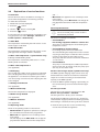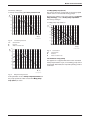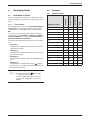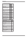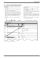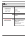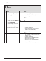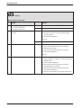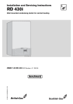
1
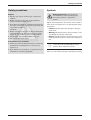
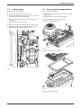
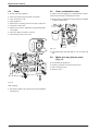
Service booklet for the Engineer
for Gas Condensing Boilers
6 720 611 400-00.1O
7 181 465 347 (05.01) OSW
ZWBR 7-30 R 30 HE plus combi GC-Number: 41 311 79
ZWBR 11-35 R 35 HE plus combi GC-Number: 41 311 80
ZWBR 11-40 R 40 HE plus combi GC-Number: 41 311 81
ZSBR 7-30 RD 430i system GC-Number: 41 108 06
ZWBR 7-32 RD 532i combi GC-Number: 41 108 10
ZWBR 11-37 RD 537i combi GC-Number: 41 108 11
ZWBR 11-42 RD 542i combi GC-Number: 41 108 12
Contents
Contents
Safety precautions
3
Symbols
3
1
4
Layout of Appliance
2
2.1
2.2
2.3
2.4
2.5
Operation
Initialisation
Standard display
Displaying service functions
Setting service functions
Resetting service functions to factory
settings
2.5.1 Resetting service functions 0.0 to 4.9 to
their factory settings (Reset 1):
2.5.2 Resetting service functions 0.0 to 9.9 to
the factory setting (Reset 2):
5
5
5
5
6
6.2
6.3
6.4
6.5
Appendix
NTC values
Flue sensor
Outside temperature sensor
CH flow NTC sensor, DHW cylinder NTC
sensor 1 and hot water NTC sensor
Electrical wiring diagram
Approved corrosion inhibitors and
anti-freeze fluids for central heating water
List of Code plugs used with
this appliance
Summary of BDH Information Sheet on
Identifying Corrosion by CFCs
50
50
50
50
50
51
52
52
53
6
6
6
3
3.1
3.2
Boiler service functions
Summary
Explanation of service functions
7
7
10
4
4.1
4.1.1
4.2
4.2.1
4.2.2
4.3
4.4
4.5
4.5.1
4.5.2
Rectifying faults
Indication of faults
... on the boiler
Summary
Appliance faults
Faults that are not displayed
Notes on using the fault code tables
Error codes on the display
Faults that are not displayed
Appliance faults
Programmer faults
15
15
15
15
15
16
17
18
36
36
43
5
5.1
5.2
5.3
5.4
5.5
5.6
5.7
5.8
5.9
Replacement of Parts
PCB control board and transformer
Fan Assembly
Primary Heat exchanger/Burner
Pump
Clean condensation trap
Motor of 3-way diverter valve (Fig. 14)
3-way diverter valve
Domestic Hot Water Heat Exchanger
Electrode assembly
46
46
47
47
48
48
48
49
49
49
2
6
6.1
6.1.1
6.1.2
6.1.3
7 181 465 347 (05.01)
Safety precautions
Safety precautions
Repairs
B Repairs may only be carried out by an approved
installer!
B Before carrying out any work on the appliance,
switch it off at the master switch!
B Even when the appliance is switched off at the master switch, some components on the pcb inside the
control box are still live.
Therefore:
B Before carrying out any work on the electrical parts
of the appliance fully disconnect it from the power
supply (e. g. by means of fuse or circuit breaker)!
B Flue ducting must not be modified in any way.
B Use only original spare parts!
Instructions to the customer
B Advise the customer that he/she must not make any
modifications to the appliance or carry out any
repairs on it.
B Draw attention to the need for an annual service (or
maintenance contract if applicable).
7 181 465 347 (05.01)
Symbols
Safety instructions in this document
are identified by a warning-triangle symbol and are printed on a grey background.
Signal words indicate the seriousness of the hazard in
terms of the consequences of not following the safety
instructions.
• Caution indicates that minor damage to property
could result.
• Warning indicates that minor personal injury or serious damage to property could result.
• Danger indicates that serious personal injury could
result. In particularly serious cases, lives could be at
risk.
i
Notes are identified by the symbol shown
on the left. They are bordered by horizontal lines above and below the text.
Notes contain important information in cases where
there is no risk of personal injury or damage to property.
3
Layout of Appliance
1
Layout of Appliance
120
221.1
221.2
27
226
20
102
32.1
29
36
271
6
2
415
43
9
63
416
358
396
64
18
7
423
418
355
6.1
15
8.1
88
400
295
4
98
7 181 465 347-02.2O
Fig. 1
4
6
6.1
7
8.1
9
15
18
20
27
29
32.1
36
43
63
64
88
98
4
Bosch Heatronic
Temperature limiter for heat exchanger
Hot water NTC sensor (combi boiler)
Testing point for gas supply pressure
Pressure gauge
Flue gas temperature limiter
Relief valve
Pump
Expansion vessel
Automatic air vent
Air gas Mixer unit
Electrode assembly
Temperature sensor in CH flow
CH flow
Adjustable gas flow restrictor
Adjusting screw for min. gas inlet flow volume
3-way valve
DHW flow switch (combi)
102
120
221.1
221.2
226
271
295
355
358
396
400
415
416
418
423
Inspection window
Fixing points
Flue duct
Combustion air intake
Fan
Flue duct
Appliance type sticker
Plate-type domestic hot water heat exchanger (combi boiler)
Condensate trap
Condensation trap hose
Text display
Cover plate for cleaning access
Condensate collector
Data plate
Siphon
7 181 465 347 (05.01)
Operation
2
Operation
Instructions on the use of the text display module are
given in the operating and installation instructions for
the boiler.
a
b
c
C
6 720 610 337-08.1R
f
Fig. 2
a
b
c
d
e
f
e
d
Controls
Display
“Up”/“More” button
“Down”/“Less” button
“Back” button
“Next” button
“Delete” button
2.1
2.3
Displaying service functions
B Press any button to activate the main menu.
B Press
or
button until the arrow cursor is
pointing to Settings.
B Press the
button.
B Press
or
button until the arrow cursor is
pointing to Service.
B Press the
button.
B Press
button to select Display service
param.
Service function 0.0 Last fault is displayed.
B Press
or
button to cycle through the
current settings.
B Press
button to exit the menu.
Initialisation
When the appliance is switched on it performs a selftest which takes about 5 seconds. While the self-test is
in progress, the text display shows Please wait... Initialising and the two-digit display shows the following
sequence of codes which appear for varying lengths of
time:
(P0,)1) P2, P3, P4, P6
On completion of the test sequence the appliance is
ready for operation.
2.2
Standard display
The text display shows the time, the CH flow temperature and the room temperature of TR2 location (if fitted).
In addition, the 2-digit display also shows the current
CH flow temperature in Heating mode and Hot Water
mode (display range 00˚C to 99˚C).
1) only for PCBs produced after 08/2004
7 181 465 347 (05.01)
5
Operation
2.4
Setting service functions
B Press any button to activate the main menu.
B Press
or
button until the arrow cursor is
pointing to Settings.
B Press the
button.
B Press
or
button until the arrow cursor is
pointing to Service.
B Press the
button.
The cursor is pointing to Display service param.
B Press and hold the
button (for about 5 seconds) until the display shows Adjust service
parameters and the first service function to be set,
e. g. 2.0 Operating mode. If a fault has occurred,
the display will show 0.0 and the last fault.
B Press
or
button until the desired service
function is displayed.
B Press the
button.
The first line of the display shows Change value,
the second line shows the value that can be
changed.
B Use the
and
buttons to enter the
required setting.
B Press the
button.
The text display shows
ATTENTION
Store settings ?
B Press
or
to select yes or no.
B Press
to confirm your selection.
The text display shows Please wait..., and the service function is then displayed with the new setting.
B Press the
or
button until the next function you wish to change is displayed.
-orB Press
button to exit the menu.
6
2.5
Resetting service functions to factory settings
2.5.1
Resetting service functions 0.0 to 4.9 to
their factory settings (Reset 1):
B Power OFF the appliance.
B Press the button
and keep it pressed.
B Switch on the appliance, press and hold the
ton until the
display shows r1 followed by [ ] .
2.5.2
but-
Resetting service functions 0.0 to 9.9 to
the factory setting (Reset 2):
B Power OFF the appliance.
B Simultaneously press and hold buttons
and
.
B Switch on appliance, press and hold the
and
buttons until the display shows r2 followed by [ ].
i
To reset all parameters (except service
settings) set on the text display module):
B Press and hold the C button until the
settings are deleted.
7 181 465 347 (05.01)
Boiler service functions
3
Boiler service functions
3.1
Summary
Range adjustable
from - to
Text display message
Display
Reset Value
0.0
Last fault
00 - FF
last fault code can be
deleted
0
0.1
Flow temp. sensor
0 - 99˚C
-
-
0.2
Hot water temp. sensor
0 - 99˚C
-
-
0.3
Stor. tank temp.sensor1
(system boiler)
0 - 99˚C
-
-
0.4
Stor. tank temp.sensor2
(not applicable)
-
-
-
1.2
Code plug 8714411 XXX
0 - 255
-
-
1.4
Voltage at terminal 2
(not applicable)
-
-
-
1.5
Required flow temp.
(for CH)
0 - 99˚C
-
-
1.8
Power set by module
(not applicable)
-
-
-
1.9
Module detection (not applicable)
-
-
-
2.0
Operating mode
-
normal
Min
Max
normal
2.2
Pump switch mode
-
1-3
3
2.3
Stor. tank charge outp.
-
0 - 100%
100 %
2.4
Anti-cycle mode
-
0 - 15 min
3 min
2.5
Max. flow temperature
-
35 - 88˚C
88˚C
2.6
Switch.diff.flow temp.
-
0 - 30˚C
0,0 K
2.7
Autom. anti-cycle mode
(not applicable)
-
on
off
on
2.9
Actual output
0 - 100 %
-
-
3.0
Fan speed
0 - 255 Hz
-
-
3.3
Ionisation current
no
low
middle
high
-
-
Table 1
7 181 465 347 (05.01)
7
Boiler service functions
Text display message
Display
Range adjustable
from - to
Reset Value
3.4
Pump mode (not applicable)
-
-
-
3.5
Pump blocking time
(not applicable)
-
0 - 240 s
in 15-s increments
0s
3.6
Software version
BF 11.XX
-
-
3.9
Link 8-9
open
closed
-
-
Link Ls-Lr
open
closed
-
-
4.0
Stor. tank. therm. (7-9)
(system boiler)
blocked
heat demand
-
-
4.1
Room therm. LSM/LSM release
(not applicable)
-
-
-
4.2
Timer ch. 1 (heating)
blocked
heat demand
-
-
Timer ch. 2 (hot wat.)
blocked
heat demand
-
-
Heat demand (heating)
yes
no
-
-
Heat demand (stor. tank)
(system boiler)
yes
no
-
-
Heat demand (hot water).
yes
no
-
-
Keep hot period
yes
no
-
-
4.6
Internal regulator
blocked
heat demand
-
-
5.0
Max. output (heating)
-
27 - 100%
100 %
5.1
Permanent ignition
-
no
yes
no
5.2
GFA status/error (not applicable)
-
-
-
5.5
Min. output (not applicable)
-
27 - 100 %
depends on boiler type
6.0
Starting load
-
1-5
3
6.6
Thermostore satisfied
(not applicable)
-
-
-
4.4
4.5
Table 1
8
7 181 465 347 (05.01)
Boiler service functions
Range adjustable
from - to
Text display message
Display
Reset Value
6.7
Pump off (hot water)
(not applicable)
-
off
on
on
6.8
Cycle time (hot water)
(combi only)
-
20 - 60 min
20 min
6.9
Duration (hot water)
(combi/system)
-
0 - 30 min
1 min
7.0
Pump map (heating)
-
0 Pump step adjustable
1 Const. pressure high
2 Const. pressure
middle
3 Const. pressure low
4 Prop.pressure high
5 Prop.pressure low
3 Const. pressure low
7.1
Map pump step (heat.)
-
2-7
7
7.2
Antiblock. map pump.
-
off
on
on
7.3
Air purge mode
(burner keeps off while air purge
mode is on)
-
off
on autom. deactivat.
permanent on
off
7.4
Actual map pump step
2-7
-
-
7.5
Map pump load index
0 - 255
-
-
7.6
Map pump type
0 - 99
(0 = no
map pump
detected)
-
-
7.7
Output reduction
-
off
only in heating mode
only in hot wat. mode
in heat./hot wat. mode
in heat./hot wat. mode
8.5
Siphonfillprogram
-
on, boiler min.output,
on, adjust. min. output,
off
on, adjust. min. output
9.1
Min. fan overrun
-
10 - 600 sec
30 sec
9.2
Hot water on demand
-
off
on
on
9.3
GFA-Asic-error (not applicable)
Table 1
7 181 465 347 (05.01)
9
Boiler service functions
3.2
Explanation of service functions
0.0 Last fault
The last fault can also be recalled for servicing purposes when the appliance is functioning correctly.
To delete the stored fault:
B
B
B
B
Delete fault (no fault displayed).
Press the
button.
Use the
button to select yes.
Press the
button.
If a list of the last 10 indicated faults is required for servicing purposes, look under Settings -> Service ->
Further options -> Fault history.
and – – .
• Max mode: the appliance runs constantly at maximum output.
The text display shows Max mode. The 2-digit display alternates between the CH flow temperature
and – –.
2.2 Pump switch mode
i
If an outside temperature driven control
unit is connected, pump control mode 3 is
automatically activated.
The choice of settings is as follows:
0.1 Flow NTC
The temperature measured by the NTC sensor on the
CH flow pipe is indicated.
• Control Mode 1
For heating equipment without a control unit.
The pump is controlled by the central heating flow
temperature control.
0.2 Hot water NTC
The temperature measured by the NTC sensor on the
plate-type heat exchanger outflow is indicated.
• Control Mode 2 (factory setting)
For heating systems with room thermostat.
The central heating flow temperature control controls
only the gas, the pump is not affected. The room thermostat controls both the gas and the pump.
The pump and fan have an overrun time of between
15 s and 3 min.
0.3 Stor. tank temp.sensor 1 (system boiler only)
Indirectly heated DHW cylinder:
The temperature measured by NTC sensor 1 on the
DHW cylinder is indicated.
0.4 Stor. tank temp.sensor 2
(not applicable)
• Control Mode 3
The pump is controlled by the outside temperature
driven control unit. In summer mode, the pump operates only for hot water mode.
1.2 Code plug
The 10-digit part number of the code plug is indicated.
The code plug determines the appliance functions. If
the appliance is converted from natural gas to LPG or
vice versa (using conversion kit) the code plug also has
to be changed.
2.3 Stor. tank charge output (system boiler only)
The DHW cylinder charging output can be set to any
level between the minimum and maximum rated heat
output for hot water according to the heat transfer
capacity of the DHW cylinder.
1.4 Voltage at terminal 2
(not applicable)
B Enter the DHW cylinder charging output setting on
the commissioning record enclosed with the appliance.
1.5 Desired flow temp.
The CH flow temperature is displayed.
1.8 Power set by module
(not applicable)
1.9 Module detection
(not applicable)
2.0 Operating mode
There are 3 operating modes to choose from.
2.4 Anti-cycle mode
This function is only active if service function 2.7
Autom. anti-cycle mode is disabled.
The anti-cycle time is factory set to 3 minutes.
The shortest possible anti-cycle time is 1 minute (recommended for single-pipe and hot-air heating systems).
If the setting 0 is entered, the anti-cycle time is inactive.
B Enter the anti-cycle time on the commissioning
record enclosed with the appliance.
• Normal mode: the appliance operates according to
the commands received from the programmer.
• Min mode: the appliance runs constantly at minimum output.
The text display shows MIn mode. The 2-digit display alternates between the CH flow temperature
10
7 181 465 347 (05.01)
Boiler service functions
2.5 Max. flow temperature
The maximum CH flow temperature can be set to
between 35˚C and 88˚C (factory setting). Even if the
CH flow temperature control is set higher, the setting
entered for 2.5 Max. flow temperatureis not
exceeded.
2.6 Switch diff. flow NTC
The switching difference is the permissible differential
from the specified CH flow temperature. It can be set in
increments of 1 K. The adjustment range is 1 to 30 K (is
factory set to 0 K). The minimum CH flow temperature
is 45˚C.
i
^ 1 ˚C.
Note: 1K =
B Disable anti-cycle time (setting 0. of service
function 2.4).
B The switching difference setting should be entered
on the commissioning record supplied with the appliance.
2.7 Autom. anti-cycle mode
With the textdisplay connected to the appliance, the
anti-cycle time is adjusted automatically. With service
funktion 2.7 automatic adjustment of the anti-cycle time
can be disabled. This may be necessary in the case of
unfavourably dimensioned heating systems.
If automatic adjustment of the anti-cycle time is disabled, the length of the anti-cycle time must be set under
service function 2.4 Anti-cycle mode.
B If automatic adjustment of the anti-cycle time has
been disabled, this should be entered on the commissioning record enclosed with the appliance.
2.9 Actual output
The actual output of the appliance at the time viewed is
displayed.
3.0 Fan speed
The current fan speed is displayed in Hertz (Hz).
3.3 Ionisation current
The burner flame is monitored by measuring the ionisation current generated during combustion. If no ionisation current is detected, the gas valve shuts off. This
ensures that unburned gas does not escape.
3.4 Pump mode (system boiler only)
(not applicable)
3.5 Pump blocking time
(not applicable)
3.6 Software version
The version number of the software is displayed.
7 181 465 347 (05.01)
3.9 Link 8-9 /
3.9 Link Ls-Lr
When supplied, the appliance has a link fitted across
terminals 8-9 (= Heat demand). If that connection is
opened (e.g. by a limiter for an underfloor heating system), heating mode is disabled.
When supplied, the appliance has a link fitted across
terminals Ls-Lr (= Heat demand). If that connection is
opened (e. g. by an external 2-point programmer), heating mode is disabled.
4.0 Stor. tank therm. (7-9) (system)
When supplied, the appliance has no link across terminals 7- 9 (= Disabled). If that connection is closed (e. g.
by a DHW cylinder thermostat) DHW cylinder charging
is enabled.
4.1 Room therm. LSM/LSM release
(not applicable)
4.2 Timer ch. 1 (heating) /
4.2 Timer ch. 2 (hot water)
Shows the status of channel 1 of the timer integrated in
the text display.
If that channel’s status is “Heat demand”, heating mode
will be activated according to the programmer commands.
Shows the status of channel 2 of the timer integrated in
the text display.
If that channel’s status is “Heat demand”, hot water
mode will be activated according to the programmer
commands.
4.4 Heat demand (heating) /
4.4 Heat demand (stor. tank) (system only)
Heat demand (heating) shows the heat demand status
for the central heating system.
If this channel’s status is “Heat demand”, heating mode
will be activated according to the programmer commands.
Heat demand shows the heat demand status for charging the DHW cylinder.
If this channel’s status is “Heat demand”, the DHW cylinder will be charged according to the commands from
the DHW cylinder thermostat or NTC sensor.
4.5 Heat demand (hot water) /
4.5 DHW pre-heat activated (combi only)
Heat demand (hot water) shows the heat demand status for the hot water function.
If this channel’s status is “Heat demand”, the hot water
function operates according to the commands from the
hot water NTC sensor.
Keep hot period shows the constant hot water circuit
status of the heat exchanger (ECO or Comfort mode).
If this channel’s status is “Heat demand”, Comfort
mode is active. If the status is “Disabled”, ECO mode
with demand detection is active.
11
Boiler service functions
4.6 Internal regulator
The boiler has an internal anti-cycle function which prevents the burner overheating if the heat output can not
be dissipated even in Min mode. The appliance will then
switch off even when the system is calling for heat.
6.6 Thermostore satisfied
(not applicable)
It will subsequently switch on again
6.8 Cycle time (hot water) (combi only)
The appliance is supplied with the pre-heat cycle time
set to 20 minutes.
After pre-heating or a DHW demand, this function will
stipulate the period of time before the next permissible
pre-heat. This will prevent excessive pre-heat cycling.
• after 5 seconds in hot water mode,
• after 30 seconds in DHW cylinder charging mode,
• after between 25 and 60 minutes (depending on the
setting of Service Function 6.8 Cycle time (hot
water)) in response to a call for heat for maintaining
cylinder temperature,
• after 0 to 15 minutes in heating mode (depending on
the setting for service function 2.4 Anti-cycle
mode).
The anti-cycle function is cancelled by another demand
for heat.
If the anti-cycle function is to be switched off manually:
B switching the appliance off and on again at the master switch.
B activating Min or Max mode.
B briefly switching to summer mode on the temperature control for CH flow
.
5.0 Max. output (heating)
The heating output can be set to any level between min.
rated heat output and max rated heat output to limit it to
the specific heat requirements.
i
Even if the heating output is limited, the
full rated heat output remains available for
hot water or DHW cylinder charging.
The factory setting is maximum rated output – display
shows „100 %“ .
5.1 Permanent ignition
This function allows permanent ignition without gas
supply to be activated for the purposes of checking the
ignition mechanism.
i
Do not run for more than 2 minutes!
6.7 Pump off (hot water)
(not applicable)
6.9 Duration (hot water) (combi/system)
The appliance is supplied with the hot water duration
set to 1 minute.
The hot water duration specifies how long after hot
water is drawn heating mode remains disabled.
7.0 Pump map (heating)
The appliance is supplied with this function set to 3
Const. pressure low (see pump characteristics
below).
The pump map indicates how the pump is controlled in
heating mode. The pump switches between the various
pump speeds so as to reproduce the characteristic
curve selected.
Changing the pump characteristic can be helpful if a
lower pressure difference will guarantee the necessary
circulation on the basis of the system dimensions and
pump characteristic.
i
In order to save as much energy as possible and to minimise the possibility of water
circulation noise, a low characteristic
should be chosen.
The pump map can be selected within:
• 0 Pump step adjustable, see service function
7.1 Map pump step (heat.)
• 1 Const. pressure high
• 2 Const. pressure middle
• 3 Const. pressure low
• 4 Prop. pressure high
• 5 Prop. pressure low.
5.2 GFA status/error
(not applicable)
5.5 Min. output
(not applicable)
6.0 Starting load
The start speed of the combustion air fan can be
increased, where problems with excessive flue lengths
may interfere with ignition. Areas with variable wind
conditions may also benefit from this facility.
12
7 181 465 347 (05.01)
Boiler service functions
The factory setting is:
7.0 Pump map (heating) 3 Const. pressure low
H
0,6
(bar)
0,5
1
2
0,4
0,3
3
7.1 Map pump step (heat.)
This service function corresponds to the pump speed
switch used on conventional heating pumps.
However, the setting is only active if function 7.0 Pump
map (heating), is set to Pump step adjustable.
The factory setting is:
7.1 Map pump step (heat.) 7
H
0,6
0,2
(bar)
0,5
0,1
0,4
0
0
200
400
600
800
1000
1200
1400
0,3
1600
Q (l/h)
0,2
6 720 610 587-43.1O
Fig. 3
1-5
H
Q
H
Constant pressure
2
0,1
Caracteristics
Pressure
Water circulation rate
3
4
5
6
7
0
0
200
400
600
800
1000
1200
1400
1600
Q (l/h)
6 720 610 587-45.1O
0,6
Fig. 5
(bar)
0,5
2-7
H
Q
4
5
0,4
Caracteristics
Caracteristics
Pressure
Water circulation rate
7.2 Antiblock. map pump
The appliance is supplied with this function activated.
If the pump threatens to jam, an oscillating pump action
is activated. Afterwards, the required operating mode is
continued.
0,3
0,2
0,1
0
0
200
400
600
800
1000
1200
1400
1600
Q (l/h)
6 720 610 587-44.1O
Fig. 4
Proportional pressure
If this parameter is set to Pump step adjustable then
the pump speed set under function 7.1 Map pump
step (heat.) is active.
7 181 465 347 (05.01)
13
Boiler service functions
7.3 Air purge mode
The first time the appliance is switched on, a once-only
venting function is activated. The heating pump then
switches on and off at intervals. This sequence lasts
about 8 minutes.
The text display shows 7.3 Air purge mode and the
2-digit display shows 00 in alternation with the CH flow
temperature.
The automatic (27) vent must be opened and then
closed again once the venting sequence is complete.
i
The venting function can be activated
manually after servicing.
• If the venting function is set to “On, autom. deactivat.”, the function is set to “Off” once the sequence
has been completed.
7.4 Actual map pump step
Actual value of this parameter.
7.5 Map pump load index
Actual value of this parameter.
7.6 Map pump type
Encoded type of installed map pump.
7.7 Output reduction
The appliance is supplied with this function activated. It
prevents overload of the heat exchanger with high CH
flow temperatures.
The output of the burner is reduced according to the
CH flow temperature, i.e. up to 80˚C flow temperature,
full burner output is permitted. Above 80˚C, the burner
output is reduced as flow temperature increases up to
90˚C at which only minimum output is available (even
with maximum heat demand).
This function can be deactivated for hot water and/or
central heating mode.
8.5 Siphon fill program
The trap filling programme ensures that the condensation trap is filled when the appliance is first installed or
after it has been shut down for a long period: The condensation trap prevents flue gas escaping from the
appliance into the room in which it is installed.
The trap filling programme is activated:
• the appliance is switched on at the master switch
• the burner has not been in operation for at least 48
hours
• the appliance is switched from summer to winter
mode.
The next time the heating or hot water system calls for
heat, the appliance is held at minimum output for 15
minutes. The trap filling programme remains active until
the appliance has completed 15 minutes of operation at
minimum output.
The text display shows Siphonfillprogram on,
adjust. min.output and the 2-digit display alternates
between -II- and the CH flow temperature.
If the condensation trap is not filled, flue
gas can escape!
B Only deactivate the trap filling programme in order to carry out servicing
work.
B Always re-activate trap filling programme once servicing is complete.
9.1 Min fan overrun
Minimal fan overrun time after a boiler demand.
9.2 Hot water on demand
The appliance is supplied with this function activated.
This function relates to ECO mode (the
button
lights).
The demand detection function enables maximum gas
and water economy.
Briefly turning a hot water tap on and then off again signals demand to the appliance which then heats up the
water to the set temperature.
Hot water is then available at short notice.
9.3 GFA-Asic-error
(not applicable)
14
7 181 465 347 (05.01)
Summary
4.2.1
Appliance faults
Indication of faults
Faults are indicated by a letter code. This helps to identify and eliminate the cause of the fault quickly and reliably.
4.1.1 ... on the boiler
The text display shows the message Fault EA. Please
call service, for example.At the same time, the fault
code appears on the 2-digit display, in this example:
EA.
You can view an explanatory description of the fault
indicated by going to Settings -> Service -> Display
service parameters , in this example: EA: During
operation: Flame not detected.
Appliance faults
Page
4.1
4.2
combi boiler
Rectifying faults
Category
4
system boiler
Rectifying faults
A1
1
X
X
18
A7
3
X
X
19
A8
3
X
X
20
Ad
3
X
X
21
b1
2
X
X
22
C1
2
X
X
23
d3
2
X
X
24
• Category 1:
The appliance is disabled until it has been switched
off and then on again.
E2
2
X
X
25
E9
4
X
X
26
• Category 2:
The appliance is disabled until the cause of the fault
has been eliminated.
EA
4
X
X
28
F0
2/4
X
X
32
F7
4
X
X
33
FA
4
X
X
33
FC
3
X
X
35
Fd
4
X
X
35
The fault codes displayed are grouped into four categories:
• Category 3:
The appliance continues to operate with limited function.
• Category 4:
The appliance is disabled and locked (
flashes)
until the cause of the fault has been eliminated and
the appliance unlocked.
i
Table 2
Unlocking the appliance:
B Press the reset button
until the digit
– – appears on the display.
Once the appliance starts up successfully, the fault disappears from the text
display.
7 181 465 347 (05.01)
15
Rectifying faults
combi boiler
Faults that are not displayed
system boiler
4.2.2
Page
Boiler indicates P1, P2, P3 at
start-up and then restarts with
P1..
X
X
36
Excessive burner noise, rumbling
noises
X
X
36
Flue gas levels incorrect, CO
level too high
X
X
38
Ignition too harsh, ignition poor
X
X
39
Loose or broken contact on
DHW cylinder NTC sensor
X
40
Hot water has unpleasant odour
or is dark colour (system boiler)
X
41
Text display fails to respond, no
display or display incorrect
X
X
41
Condensation in the flue pipe
X
X
41
X
42
Appliance faults
Inadequate hot water outlet temperature (combi boiler)
Table 3
Programmer faults
Page
Set room temperature not reached (TR 2)
43
Set room temperature not reached (integrated text display)
43
Set room temperature exceeded by large
amount (TR 2)
44
Heating up takes too long (integrated text
display)
44
Excessive fluctuations in room temperature
(integrated text display)
45
Room temperature too high in Economy
mode
45
Incorrect or no modulation
45
No programmer display or programmer display does not react
45
Table 4
16
7 181 465 347 (05.01)
Rectifying faults
4.3
Notes on using the fault code tables
The procedure is best described with the aid of
an example:
• Work through the table from top to bottom and from
left to right.
• First make a note of the present settings and restore
them before leaving the appliance.
• Read question 1. (Check column)and depending on
the answer (yes or no) read the action required from
the relevant box and carry out the instruction given;
ignore the other answer. For example: if the burner
flame is visible, follow the instructions for yes,
i.e. ↓5.!
• ↓5. means go to number 5., ignoring the steps in
between.
EA
and
In this example: check the flue is clear by testing
the CO2 level.
• If the appliance is locked (
press the
button.
button is flashing),
• If the fault has been rectified, the appliance will then
start up without indicating a fault and the fault isolation procedure is complete.
• If the fault is still present after performing the action
specified and, if necessary, restarting the appliance,
move on to the next step in the fault isolation procedure.
• If another fault code is displayed, work through the
fault code table for that code.
flashing.
Flame not detected
Check
1.
2.
Is a burner flame visible?
Is the gas cock turned on?
Action
yes:
↓ 5.
no:
↓ 2.
yes:
Ø 5.
no:
B Open the gas cock.
B Press button
.
EA? ↓3.
3.
Has the thermal cut-out on the gas
cock tripped?
4. ...
...
5. ...
Problem with flue?
B Check CO2 level in combustion
air.
Is CO2 level above 0,2 % ?
yes:
...
no:
↓ ...
yes:
Check flue.
no:
↓ ...
7181465347-01.1O
Fig. 6
Example of fault code table
7 181 465 347 (05.01)
17
Rectifying faults
Error A1
4.4
Error codes on the display
A1
flashing.
Controlled-characteristic pump has run dry
Check
1.
System pressure below 1.2 bar?
Action
yes:
B Power OFF the appliance.
B Check appliance and system for water leaks and
repair as necessary.
B Fill system, bleed and re-pressurise (see Installation Instructions).
B Turn ON the appliance.
A1? ↓2.
2.
3.
18
Audible bearing damage on pump?
Activate venting sequence.
no:
↓2.
yes:
B
B
B
B
B
no:
↓3.
yes:
B Activate menu option Show service parameters.
B Select 7.3 Air purge mode select setting on,
autom. deactivat. and confirm.
B Vent appliance.
B Vent radiators.
Power OFF the appliance.
Disconnect the boiler electrical connection.
Drain appliance.
Change the pump (see chapter 5.4).
Fill system, bleed and re-pressurise (see Installation Instructions).
B Reconnect the boiler electrical connection.
B Turn ON the appliance.
↓3.
7 181 465 347 (05.01)
Rectifying faults
Error A7
A7
flashing.
Water NTC sensor defective
Check
1.
2.
3.
1)
Action
B Activate menu option Show service parameters.
B Select service function 0.2 Hot
water temp. sensor.
Is a temperature between 0 and
5˚C displayed?
yes:
no:
↓2.
B Unplug 20-pin connector from
PCB.
E2 is displayed.
B Check resistance from connections 3 to 4 on the cable side.
Does the value match the ones
described in table 7, page 50?
yes:
B Make a note of the altered service function settings (see table 1 on page 7) in order to keep the
altered values.
B Power OFF the appliance.
B Disconnect the boiler electrical connection.
B Change PCB control board.
B Reconnect the boiler electrical connection.
B Turn ON the appliance.
B Restore service settings previously noted down.
no:
↓3.
yes:
B
B
B
B
B
no:
B Change NTC sensor.
B Unplug NTC sensor from cable.
B Check resistance of NTC sensor.
Does the value match the ones
described in table 7, page 50?
DHW temperature limiter connector corroded 1),
damaged or dirty?
B Change relative parts.
A7?↓2.
Power OFF the appliance.
Disconnect the boiler electrical connection.
Change the 20-pin connector lead assembly.
Reconnect the boiler electrical connection.
Turn ON the appliance.
For notes, refer to Appendix
7 181 465 347 (05.01)
19
Rectifying faults
Error A8
A8
flashing.
No correct electrical connection
Check
1.
B Power OFF the appliance.
B Check Wiring between Textdisplay and TR 2:
– Terminal 3 on Textdisplay connected to Terminal 3 TR 2?
– Terminal 4 ...Terminal 4
– Terminal F ...Terminal F?
Action
yes:
↓2.
no:
B Rewire correctly as specified in the installation
instructions.
B Turn ON the appliance.
After 90 sec.:
A8?
B Power OFF the appliance.
↓2.
2.
B Check continuity on wiring to TR 2.
Is there continuity?
yes:
↓3.
no:
B Replace or repair wiring and/or connections.
B Turn ON the appliance.
After 90 sec.:
A8?
B Power OFF the appliance.
↓3.
3.
4.
20
B Check resistance from connections
4 to F and 3 to 4.
Is resistance between XX and XX?
The PCB control board is damaged.
yes:
B Replace TR 2.
no:
↓4.
B Make a note of the altered service function settings (see table 1 on page 7) in order to keep
the altered values.
B Power OFF the appliance.
B Disconnect the boiler electrical connection.
B Change PCB control board.
B Reconnect the boiler electrical connection.
B Turn ON the appliance.
B Restore service settings previously noted down.
7 181 465 347 (05.01)
Rectifying faults
Error Ad
Ad
flashing.
DHW cylinder NTC sensor not detected
Check
1.
Is lead for DHW cylinder NTC sensor
correctly routed, i.e. not through
cable clamp?
Action
yes:
↓2.
no:
B Route connecting lead for DHW cylinder temperature sensor as specified in installation
instructions.
Ad? ↓2.
2.
B Activate menu option Show service parameters.
B Select 0.3 Stor. tank
temp.sensor1.
Is a temperature between 0 and
5˚C displayed?
yes:
If DHW cylinder sensor connector corroded, damaged or dirty:
B Power OFF the appliance.
B Change NTC sensor.
B Turn ON the appliance.
B Press button
.
Ad? ↓3.
3.
4.
B Unplug DHW cylinder NTC connector from PCB control board.
B Check resistance from connections 3 to 4 on the cable side.
Does the value match the ones
described in table 7, page 50?
B Unplug NTC sensor from cable in
DHW cylinder.
B Check resistance of NTC sensor.
Does the value match the ones
described in table 7, page 50?
7 181 465 347 (05.01)
no:
↓3.
yes:
B Make a note of the altered service function settings (see table 1 on page 7) in order to keep
the altered values.
B Power OFF the appliance.
B Disconnect the boiler electrical connection.
B Change PCB control board.
B Reconnect the boiler electrical connection.
B Turn ON the appliance.
B Restore service settings previously noted down.
no:
↓4.
yes:
B
B
B
B
B
no:
B Change NTC sensor.
Power OFF the appliance.
Disconnect the boiler electrical connection.
Change the NTC sensor connection cable.
Reconnect the boiler electrical connection.
Turn ON the appliance.
21
Rectifying faults
Error b1
b1
flashing.
Code plug not detected.
Check
1.
b1 is shown on 2 digit display.
(independent on what is shown on
the text display).
Action
yes:
B Power OFF the appliance.
B Fit code plug (correctly), making sure code
number is correct (see Appendix).
B Turn ON the appliance.
b1? ↓2.
2.
3.
B Activate menu option Show service parameters.
B Select 1.2 Code plug.
B Compare number displayed with
that shown in Appendix.
No number or incorrect number
(last three digits) displayed.
Code plug loose, incorrect or defective.
no:
↓2.
yes:
↓3.
no:
↓4.
B Power OFF the appliance.
B Fit code plug (correctly), making sure code
number is correct (see Appendix).
B Turn ON the appliance.
b1? ↓4.
4.
22
The PCB control board is damaged.
B Make a note of the altered service function settings (see table 1 on page 7) in order to keep
the altered values.
B Power OFF the appliance.
B Disconnect the boiler electrical connection.
B Change PCB control board.
B Reconnect the boiler electrical connection.
B Turn ON the appliance.
B Restore service settings previously noted down.
7 181 465 347 (05.01)
Rectifying faults
Error C1
C1
flashing.
Fan speed too low
Check
1.
Fan lead connector properly connected?
Action
yes:
↓2.
no:
B Power OFF the appliance.
B Plug in connector.
B Turn ON the appliance.
C1? ↓2.
2.
Is fan lead defective?
B Measure the fan lead for
continuity.
Is there continuity for each one of
the cores?
yes:
↓3.
no:
B Power OFF the appliance.
B Replace fan lead.
B Turn ON the appliance.
C1? ↓3.
3.
Fan defective.
yes:
B
B
B
B
B
Power OFF the appliance.
Unplug the connection wire.
Replace fan.
Plug the connection wire.
Turn ON the appliance.
C1? ↓4.
no:
4.
The PCB control board is damaged.
7 181 465 347 (05.01)
↓4.
B Make a note of the altered service function settings (see table 1 on page 7) in order to keep
the altered values.
B Power OFF the appliance.
B Disconnect the boiler electrical connection.
B Change PCB control board.
B Reconnect the boiler electrical connection.
B Turn ON the appliance.
B Restore service settings previously noted down.
23
Rectifying faults
Error d3
d3
flashing.
Wrong signal from pin 8-9.
Check
1.
2.
Action
B Measure voltage between Terminal 4 and Terminal 8.
Voltage ≅ 24 V DC?
yes:
↓2.
no:
↓3.
Link between terminals 8 and 9 connected?
yes:
B Power OFF the appliance.
B Check link across 8-9 properly fitted, tighten
screws properly.
B Turn ON the appliance.
d3? ↓3.
no:
3.
Terminal block defective.
↓3.
B
B
B
B
B
Power OFF the appliance.
Disconnect the boiler electrical connection.
Replace terminal strip.
Reconnect the boiler electrical connection.
Turn ON the appliance.
d3? ↓4.
4.
24
The PCB control board is damaged.
B Make a note of the altered service function settings (see table 1 on page 7) in order to keep the
altered values.
B Power OFF the appliance.
B Disconnect the boiler electrical connection.
B Change PCB control board.
B Reconnect the boiler electrical connection.
B Turn ON the appliance.
B Restore service settings previously noted down.
7 181 465 347 (05.01)
Rectifying faults
Error E2
E2
flashing.
The flow temp. NTC sensor is damaged.
Check
1.
B Activate menu option Show service parameters.
B Select 0.1 Flow temp. sensor.
Is a temperature between 0 and
5˚C displayed?
Action
yes:
The heating outlet NTC sensor is in short circuit:
B Power OFF the appliance.
B Replace CH flow NTC sensor; observe fitting
instructions for NTC sensor when doing so.
B Turn ON the appliance.
E2? ↓2.
2.
3.
B Unplug 20-pin connector from
PCB.
B Check resistance from connections 8 to 9 on the cable side.
Does the value match the ones
described in table 7, page 50?
B Unplug NTC sensor from cable.
B Check resistance of NTC sensor.
Does the value match the ones
described in table 7, page 50?
7 181 465 347 (05.01)
no:
↓ 2.
yes:
B Make a note of the altered service function settings (see table 1 on page 7) in order to keep the
altered values.
B Power OFF the appliance.
B Disconnect the boiler electrical connection.
B Change PCB control board.
B Reconnect the boiler electrical connection.
B Turn ON the appliance.
B Restore service settings previously noted down.
no:
↓3.
yes:
B
B
B
B
B
no:
B Change NTC sensor.
Power OFF the appliance.
Disconnect the boiler electrical connection.
Change the 20-pin connector lead assembly.
Reconnect the boiler electrical connection.
Turn ON the appliance.
25
Rectifying faults
Error E9
E9
and
flashing.
Safety temperature limiter has tripped.
Check
1.
Is the heating pressure between 1 and
2 bar?
Action
yes:
↓2.
no:
B Top up system.
B Vent appliance.
B Press
, restart the appliance.
E9? ↓2.
2.
Is the pump seized?
yes:
B Unblock the pump.
If pump won’t start:
B Power OFF the appliance.
B Disconnect the boiler electrical connection.
B Drain appliance.
B Change the pump (see chapter 5.4).
B Fill system, bleed and re-pressurise (see Installation Instructions).
B Reconnect the boiler electrical connection.
B Turn ON the appliance.
B Press
, restart the appliance.
E9? ↓3.
3.
Lead disconnected from safety temperature limiters?
no:
↓3.
yes:
B Power OFF the appliance.
B Reconnect lead.
B Turn ON the appliance.
B Press
, restart the appliance.
E9? ↓4.
4.
B Power OFF the appliance.
B Unplug the connector from the cutoff device.
B Measure the of cut-off device for
continuity.
Resistance very high?
no:
↓4.
yes:
B Change the over heating cut-off device.
B Connect flue gas safety temperature limiter lead.
B Turn ON the appliance.
B Press
, restart the appliance.
E9? ↓5.
no:
B Connect flue gas safety temperature limiter lead.
B Turn ON the appliance.
E9? ↓5.
26
7 181 465 347 (05.01)
Rectifying faults
Error E9
E9
and
flashing.
Safety temperature limiter has tripped.
Check
5.
Is lead disconnected from CH flow
safety temp. limiter?
Action
yes:
B Power OFF the appliance.
B Reconnect lead.
B Turn ON the appliance.
B Press
, restart the appliance.
E9? ↓6.
6.
B Power OFF the appliance.
B Disconnect lead to CH flow safety
temperature limiter.
B Measure the CH flow safety temperature limiter for continuity.
Resistance very high?
no:
↓6.
yes:
B Change CH flow safety temperature limiter.
B Connect CH flow safety temperature limiter.
B Turn ON the appliance.
B Press
, restart the appliance.
E9? ↓7.
no:
B Connect CH flow safety temperature limiter.
B Turn ON the appliance.
↓7.
7.
B Power OFF the appliance.
B Remove fuse SI 3 from appliance
PCB control board and test for
continuity.
Resistance very high?
yes:
B Change the fuse.
B Turn ON the appliance.
B Press
, restart the appliance.
E9? ↓8.
no:
B Remount the fuse.
B Turn ON the appliance.
↓8.
8.
The PCB control board is damaged.
7 181 465 347 (05.01)
B Make a note of the altered service settings (see
table 1 on page 7).
B Power OFF the appliance.
B Disconnect the boiler electrical connection.
B Change PCB control board.
B Reconnect the boiler electrical connection.
B Turn ON the appliance.
B Restore service settings previously noted down.
27
Rectifying faults
Error EA
EA
and
flashing.
During operation: flame not detected
Check
1.
Is a burner flame visible?
2.
Is the gas cock turned on?
Action
yes:
↓5.
no:
↓2.
yes:
↓3.
no:
B Open the gas cock.
B Press
, restart the appliance.
EA? ↓3.
3.
Is there air in the supply pipe?
yes:
B Vent supply pipe.
B Press
, restart the appliance.
EA? ↓4.
4.
Natural gas models:
does the building have a supply pressure
regulator?
no:
↓4.
yes:
B Check that it is fitted correctly and functioning properly and correct if necessary.
B Check supply pressure, inform gas company if outside
correct range.
B Is correct code plug fitted?
B Press
, restart the appliance.
EA? ↓5.
LPG models:
is the flow rate of the gas supply to the
appliance correct?
no:
↓5.
yes:
↓5.
no:
B Is there enough gas in the supply cylinder?
B Is there air in the supply pipe?
B Is the solenoid valve in the "meter cabinet” opening?
B Is the supply pressure OK? (if the supply pressure is
too high, check the pressure regulator in the “meter
cabinet” and on the LPG supply cylinder)
B Press
, restart the appliance.
EA? ↓5.
5.
Is the earth connection correct?
yes:
↓6.
no:
B Correct the electrical connection.
B Press
, restart the appliance.
EA? ↓6.
6.
Is the condensation trap blocked?
yes:
B Clean out condensation trap discharge pipe.
B Press
, restart the appliance.
EA? ↓11.
no:
28
↓7.
7 181 465 347 (05.01)
Rectifying faults
Error EA
EA
and
flashing.
During operation: flame not detected
Check
7.
Is diaphragm in mixer unit fitted correctly
(see installation instructions)?
B Open mixer unit (29).
B Check diaphragm for correct orientation, soiling and splitting.
Is diaphragm OK?
Action
yes:
B Close mixer unit.
↓8.
no:
B Insert diaphragm in the fan intake duct as per installation instructions so that the flaps open upwards.
B Close mixer unit.
EA? ↓8.
8.
Check the gas valve.
yes:
B Reconnect the connectors.
B Power OFF the appliance.
B Turn ON the appliance.
B Unplug the connectors from the gas
valve.
B Press
B Measure the gas valve coils I and II
electrical resistance at 20-pin connector.
R = 164±40 Ω?
EA? ↓9.
no:
, restart the appliance.
B Power OFF the appliance.
B Turn off gas cock.
B Change the gas valve.
B Open the gas cock.
B Reconnect the boiler electrical connection.
B Reconnect the connectors.
B Turn ON the appliance.
B Check appliance for leaks.
B Press
, restart the appliance.
EA? ↓9.
9.
Problem with flue?
yes:
B Open up heat exchanger - is it dirty?
B Check flue, clean if necessary.
Combined air/flue stack (LAS):
B Check CO2 level in combustion air.
Is CO2 level above 0,2 % ?
B Check connection is fully inserted and not leaking.
B Is distance between flue entry and lowest combustion
source at least 2.5 m?;
PLEWA only: at least 1.25 m with 45˚ flue entry.
B Cross-sectional area adequate? If necessary contact
chimney stack manufacturer.
Flue on outside of building:
B Unrestricted cross-sectional area of air intake OK?
If Junkers flue used in stack (counter-flow) and
solid-fuel boiler in adjacent stack:
B Is flue for solid-fuel boiler raised as per ZIV recommendations? (does not apply if approved chimney terminal
fitted)
Then:
B Press
, restart the appliance.
EA? ↓10.
no:
7 181 465 347 (05.01)
↓10.
29
Rectifying faults
Error EA
EA
and
flashing.
During operation: flame not detected
Check
10.
Is flue gas CO2 level
Action
incorrect1)?
yes:
B Adjust to correct level.
B Press
, restart the appliance.
EA? ↓11.
11.
B Activate menu option Show service
parameters.
B Select 5.1 Permanent ignition
(without Gas).
Continuous ignition (without gas) OK?
no:
↓11.
yes:
B Press
button to select no.
↓12.
no:
B Press
button to select no.
↓15.
12.
Ignition lead connected to ignition electrodes?
yes:
↓13.
no:
B Reconnect lead.
B Press
, restart the appliance.
EA? ↓13.
13.
Ignition cable connector engaged in
switchbox?
yes:
↓14.
no:
B Power OFF the appliance.
B Engage ignition cable connector in switchbox.
B Turn ON the appliance.
B Press
, restart the appliance.
EA? ↓14.
14.
Is the ignition electrical wire
damaged?
yes:
B Power OFF the appliance.
B Change the ignition electrical wire.
B Turn ON the appliance.
B Press
, restart the appliance.
EA? ↓15.
15.
B Activate menu option Show service
parameters.
no:
↓15.
yes:
↓17.
no:
↓16.
yes:
B Replace electrode assembly.
B Select 3.3 Ionisation current .
Measured ionisation current medium
or high?
16.
Electrode assembly defective?
B Power OFF the appliance.
B Turn ON the appliance.
B Remove electrode assembly.
Electrode assembly burnt out?
B Press
, restart the appliance.
EA? ↓17.
no:
B Refit electrode assembly.
B Turn ON the appliance.
B Press
, restart the appliance.
EA? ↓17.
30
7 181 465 347 (05.01)
Rectifying faults
Error EA
EA
and
flashing.
During operation: flame not detected
17.
Check
Action
Check if the 20-pin connector lead
assembly is damaged.
B Power OFF the appliance.
B Change the 20-pin connector lead assembly.
B Turn ON the appliance.
B Press
, restart the appliance.
EA? ↓18.
18.
The PCB control board is damaged.
B Make a note of the altered service settings (see
table 1 on page 7).
B Power OFF the appliance.
B Disconnect the boiler electrical connection.
B Change PCB control board.
B Reconnect the boiler electrical connection.
B Turn ON the appliance.
B Restore service settings previously noted down.
1)
See installation instructions
7 181 465 347 (05.01)
31
Rectifying faults
Error F0
F0
(and possibly
) flashing.
Internal failure
1.
2.
3.
4.
Check
Action
B Activate menu option Show service parameters.
B Select 9.3 GFA-Asic error
(automatic ignition module,
extended messages).
A message is displayed.
B Enter figure displayed in customer service record.
B Select 5.2 GFA status/error .
A message is displayed.
B Enter figure displayed in customer service record.
B Select Settings -> Further
options-> Service->Display
service param.
Other faults apart from F0 displayed?
flashing?
↓2.
↓3.
yes:
B Deal with fault(s) displayed as instructed in relevant fault table(s).
no:
↓4.
yes:
B Press button
.
B Initiate demand for heat by pressing
.button
and then press again after 30 seconds to cancel.
B Initiate two more demands for heat as above.
F0? ↓5.
no:
5.
32
The PCB control board is damaged.
↓5.
B Make a note of the altered service settings (see
table 1 on page 7).
B Power OFF the appliance.
B Disconnect the boiler electrical connection.
B Change PCB control board.
B Reconnect the boiler electrical connection.
B Turn ON the appliance.
B Restore service settings previously noted down.
7 181 465 347 (05.01)
Rectifying faults
Error F7
F7
and
flashing.
Although appliance switches off, flame still detected
Check
1.
Action
Electrode(s) dirty or defective?
yes:
B Power OFF the appliance.
B Remove electrode assembly and
bracket and check for wear,
deposits and mechanical damage.
B Replace electrode assembly.
B Turn ON the appliance.
B Press
, restart the appliance.
F7? ↓2.
no:
B Refit electrode assembly.
B Turn ON the appliance.
B Press
, restart the appliance.
F7? ↓2.
2.
3.
Problem with flue?
B Check CO2 level in combustion
air.
Is CO2 level above 0,2 % ?
yes:
B Check flue and repair or replace if necessary.
no:
↓3.
B Make a note of the altered service settings (see
table 1 on page 7).
B Power OFF the appliance.
B Disconnect the boiler electrical connection.
B Change PCB control board.
B Reconnect the boiler electrical connection.
B Turn ON the appliance.
B Restore service settings previously noted down.
The PCB control board is damaged.
FA
and
flashing.
After appliance switches off flame is detected
Check
1.
Is the condensation trap blocked?
Action
yes:
B Power OFF the appliance.
B Clean out condensation trap discharge pipe.
B Turn ON the appliance.
B Press
, restart the appliance.
FA? ↓2.
no:
7 181 465 347 (05.01)
↓2.
33
Rectifying faults
Error F7
FA
and
flashing.
After appliance switches off flame is detected
2.
3.
Check
Action
Electrode assembly defective?
B Power OFF the appliance.
B Remove electrode assembly.
Electrode assembly burnt out?
B Replace electrode assembly.
B Turn ON the appliance.
Problem with flue?
B Check CO2 level in combustion
air.
Is CO2 level above 0,2 % ?
B Press
FA? ↓3.
yes:
The gas valve is damaged.
B Check flue, clean if necessary.
B Press
, restart the appliance.
FA? ↓4.
no:
4.
, restart the appliance.
↓4.
B
B
B
B
B
B
B
B
Power OFF the appliance.
Disconnect the boiler electrical connection.
Turn off gas cock.
Change the gas valve.
Open the gas cock.
Reconnect the boiler electrical connection.
Turn ON the appliance.
Check appliance for leaks.
B Press
, restart the appliance.
FA?↓5.
5.
Check if the 20-pin connector lead
assembly is damaged.
B
B
B
B
B
Power OFF the appliance.
Disconnect the boiler electrical connection.
Change the 20-pin connector lead assembly.
Reconnect the boiler electrical connection.
Turn ON the appliance.
B Press
, restart the appliance.
FA? ↓6.
6.
34
The PCB control board is damaged.
B Make a note of the altered service settings (see
table 1 on page 7).
B Power OFF the appliance.
B Disconnect the boiler electrical connection.
B Change PCB control board.
B Reconnect the boiler electrical connection.
B Turn ON the appliance.
B Restore service settings previously noted down.
7 181 465 347 (05.01)
Rectifying faults
Error FC
FC
flashing.
Text display module not detected
1.
Check
Action
No fault or fault code FC displayed
on text display?
B Power OFF the appliance.
B Fit code plug (correctly), making sure code
number is correct (see Appendix).
B Turn ON the appliance.
FC? ↓2.
2.
B Unplug text display module connector.
B Connecting lead between text display module and Heatronic OK.?
yes:
B Plug in connector.
FC? ↓3.
no:
B Replace text display module.
FC? ↓3.
3.
Text display module defective.
Fd
and
B Replace text display module.
flashing.
Reset button pressed inadvertently
Check
1.
flashing?
Action
B Press
, restart the appliance.
Fd? ↓2.
2.
The PCB control board is damaged.
7 181 465 347 (05.01)
B Make a note of the altered service settings (see
table 1 on page 7).
B Power OFF the appliance.
B Disconnect the boiler electrical connection.
B Change PCB control board.
B Reconnect the boiler electrical connection.
B Turn ON the appliance.
B Restore service settings previously noted down.
35
Rectifying faults
Error Fd
4.5
Faults that are not displayed
4.5.1
Appliance faults
Boiler indicates P1, P2, P3 at start-up and then restarts with P1..
Check
1.
Fuse T 1,6 A (312) defective.
Action
yes:
B
B
B
B
B
Power OFF the appliance.
Disconnect the boiler electrical connection.
Change the fuse.
Reconnect the boiler electrical connection.
Turn ON the appliance.
Start sequence not completed? ↓2.
no:
2.
↓2.
B Make a note of the altered service settings (see
table 1 on page 7).
B Power OFF the appliance.
B Disconnect the boiler electrical connection.
B Change PCB control board.
B Reconnect the boiler electrical connection.
B Turn ON the appliance.
B Restore service settings previously noted down.
The PCB control board is damaged.
Excessive burner noise, rumbling noises
Check
1.
Does the gas supply type match the
specifications on the appliance identification plate?
Action
yes:
↓2.
no:
B Convert appliance to correct gas type.
Rumbling noises? ↓2.
2.
3.
36
B Test gas supply pressure - OK?
Does pressure match figure specified in installation instructions?
yes:
↓3.
no:
B Decommission appliance.
Natural gas models:
B Notify gas company.
Problem with flue?
B Check CO2 level in combustion
air.
Is CO2 level above 0,2 % ?
yes:
B Check flue and repair or replace if necessary.
Rumbling noises? ↓4.
no:
↓4.
7 181 465 347 (05.01)
Rectifying faults
Error Fd
Excessive burner noise, rumbling noises
Check
4.
5.
Action
B Repair or replace components.
B Grease seal before fitting. Make sure it is fitted in
correct position.
Is appliance’s internal air/flue channel leaking or blocked?
B Open up heat exchanger and
inspect.
B Remove silencer, flue duct and air
flow limit.
B Open trap and inspect.
Air channels dirty/clogged, seals
defective or not correctly fitted?
yes:
no:
↓5.
B Measure CO2 levels.
CO2 levels in flue gas at min and
max output do not match figures
specified in installation instructions.
yes:
B Adjust CO2 level as per installation instructions.
no:
B Power OFF the appliance.
B Turn off gas cock.
7 181 465 347 (05.01)
Rumbling noises? ↓5.
B
B
B
B
Change the gas valve.
Open the gas cock.
Turn ON the appliance.
Check appliance for leaks.
37
Rectifying faults
Error Fd
Flue gas levels incorrect, CO level too high
Check
1.
Does the gas supply type match the
specifications on the appliance identification plate?
Action
yes:
↓2.
no:
B Convert appliance to correct gas type.
Flue gas levels incorrect? 2.
2.
B Test gas supply pressure - OK?
Does pressure match figure specified in installation instructions?
yes:
↓3.
no:
B Decommission appliance.
Bei Erdgas:
B Notify gas company.
b
3.
4.
5.
B Check flue and repair or replace if necessary.
Problem with flue?
B Check CO2 level in combustion
air.
Is CO2 level above 0,2 % ?
yes:
no:
↓4.
Flue gas CO2 levels measured at
min. and max. load do not match
specified levels?
B Measure CO2 levels.
yes:
B Adjust CO2 level as per installation instructions.
no:
↓5.
Gas volumetric flow too high when
CO2 level correctly set.
yes:
B Reduce gas volumetric flow rate by means of
adjusting screw on gas valve and/or gas flow
restrictor.
B Check CO2 adjustment.
Flue gas levels incorrect? 4.
Flue gas levels incorrect? 5.
Flue gas levels incorrect? 6.
no:
6.
38
↓6.
B
B
B
B
B
B
Power OFF the appliance.
Turn off gas cock.
Change the gas valve.
Open the gas cock.
Turn ON the appliance.
Check appliance for leaks.
7 181 465 347 (05.01)
Rectifying faults
Error Fd
Ignition too harsh, ignition poor
Check
1.
2.
Action
B Activate menu option Show service parameters.
B Select 5.1 Permanent ignition
(without Gas).
Continuous ignition (without gas)
OK?
yes:
↓6.
no:
↓2.
Ignition lead connected to ignition
electrodes?
yes:
↓3.
no:
B Connect cable to ignition electrodes.
B Press button
.
Ignition poor? 3.
3.
Ignition cable connector engaged in
switchbox?
yes:
↓4.
no:
B Power OFF the appliance.
B Engage ignition cable connector in switchbox.
B Turn ON the appliance.
B Press button
.
Ignition poor? 4.
4.
Is the ignition electrical wire
damaged?
yes:
B Power OFF the appliance.
B Change the ignition electrical wire.
B Turn ON the appliance.
B Press button
.
Ignition poor? 5.
5.
Electrode assembly defective?
B Power OFF the appliance.
B Remove electrode assembly.
Electrode assembly burnt out?
no:
↓5.
yes:
B Replace electrode assembly.
B Turn ON the appliance.
B Press
, restart the appliance.
Ignition poor? 6.
no:
B Refit electrode assembly.
B Turn ON the appliance.
B Press
, restart the appliance.
Ignition poor? 6.
6.
Does the gas supply type match the
specifications on the appliance identification plate?
yes:
↓7.
no:
B Convert appliance to correct gas type.
Ignition poor? 7.
7 181 465 347 (05.01)
39
Rectifying faults
Error Fd
Ignition too harsh, ignition poor
Check
7.
8.
9.
10.
Action
B Test gas supply pressure - OK?
Does pressure match figure specified in installation instructions?
yes:
↓8.
no:
B Decommission appliance.
In case of natural gas:
B Notify gas company.
Problem with flue?
B Check CO2 level in combustion
air.
Is CO2 level above 0,2 % ?
yes:
B Check flue and repair or replace if necessary.
no:
↓9.
Flue gas CO2 levels measured at
min. and max. load do not match
specified levels?
B Measure CO2 levels.
yes:
B Adjust CO2 level as per installation instructions.
Ignition poor? 9.
Ignition poor? 10.
no:
Burner not correctly fitted or defective?
B Power OFF the appliance.
B Turn off gas cock.
B Remove burner.
Cover fixings not tight
or
seal defective or not correctly fitted
or
burner defective?
↓10.
B
B
B
B
B
Replace burner and seal if necessary.
Ensure seal is fitted in correct position.
Open the gas cock.
Turn ON the appliance.
Check appliance for leaks.
Loose or broken contact on DHW cylinder NTC sensor
40
Check
Action
DHW cylinder NTC sensor lead is
not fitted as described in the installation instructions (i.e. the cable does
not pass through the cable grip in the
switchbox).
B Record condition of appliance as found in customer service record.
B Route cable as specified in installation instructions.
7 181 465 347 (05.01)
Rectifying faults
Error Fd
Hot water has unpleasant odour or is dark colour (system boiler)
Check
Action
This is generally caused by the formation of hydrogen sulphide by sulphate-reducing bacteria. Such bacteria are
found in water which is very low in oxygen and live off the hydrogen produced by the anode.
1.
B Clean the hot water cylinder.
B Replace the sacrificial anode.
B Heat cylinder to a temperature ≥60˚C
2.
B Replace magnesium sacrificial anode with
impressed-current anode.
The conversion costs are payable by the operator!
Text display fails to respond, no display or display incorrect
Check
Action
Ignition lead is not fitted as specified
in installation instructions (i.e. the
lead should be routed through the
clip on the underside of the air box).
B Hook igniter lead over clip on underside of air
box.
-orB Route igniter lead behind gas valve.
Condensation in the flue pipe
1.
Check
Action
Is diaphragm in mixer unit fitted correctly (see installation instructions)?
B Open mixer unit (29).
B Check diaphragm for correct orientation, soiling and splitting.
B Fit diaphragm as per installation instructions or
replace.
B Close mixer unit.
7 181 465 347 (05.01)
41
Rectifying faults
Error Fd
Inadequate hot water outlet temperature (combi boiler)
Check
1.
Pump set to mode 3?
Action
yes:
↓2.
no:
B Set pump switch to setting 3.
Inadequate hot water outlet temperature ? ↓2.
2.
B Unplug connector from Heatronic;
is voltage between terminal 1 and
terminal 3 230 V AC?
yes:
B
B
B
B
B
no:
B Make a note of the altered service settings (see
table 1 on page 7).
B Power OFF the appliance.
B
B
B
B
B
42
Power OFF the appliance.
Disconnect the boiler electrical connection.
Change the 20-pin connector lead assembly.
Reconnect the boiler electrical connection.
Turn ON the appliance.
Disconnect the boiler electrical connection.
Change PCB control board.
Reconnect the boiler electrical connection.
Turn ON the appliance.
Restore service settings previously noted down.
7 181 465 347 (05.01)
Rectifying faults
Error Fd
4.5.2
Programmer faults
Set room temperature not reached (TR 2)
Check
1.
Thermostatic valve(s) set too low?
Action
yes:
B Turn up thermostatic valve(s).
↓2.
2.
3.
CH flow temperature control on
boiler set too low?
no:
↓2.
yes:
B Turn up CH flow temperature control.
no:
↓3.
B Power OFF the appliance.
B Check appliance and system for water leaks and
repair as necessary.
B Top up system.
B Turn ON the appliance.
B Activate menu option Show service parameters.
B Select 7.3 Air purge mode select setting on,
autom. deactivat. and confirm.
B Vent appliance.
B Vent radiators.
Air in the heating system.
Set room temperature not reached (integrated text display)
Check
1.
Thermostatic valve(s) set too low?
Action
yes:
B Turn up thermostatic valve(s).
↓2.
2.
Heating characteristic set too low?
no:
↓2.
yes:
B Correct heating characteristic.
↓3.
3.
CH flow temperature control on
boiler set too low?
no:
↓3.
yes:
B Turn up CH flow temperature control.
↓4.
no:
7 181 465 347 (05.01)
↓4.
43
Rectifying faults
Error Fd
Set room temperature not reached (integrated text display)
4.
Check
Action
Air in the heating system.
B Power OFF the appliance.
B Check appliance and system for water leaks and
repair as necessary.
B Top up system.
B Turn ON the appliance.
B Activate menu option Show service parameters.
B Select 7.3 Air purge mode select setting on,
autom. deactivat. and confirm.
B Vent appliance.
B Vent radiators.
Set room temperature exceeded by large amount (TR 2)
Check
1.
Do radiators get too hot?
Action
yes:
B Decrease setting of “Heating” control.
↓2.
2.
Bad choice of location for programmer, e.g. outside wall, near window,
in draught, on hollow wall, etc.
no:
↓2.
yes:
B Select better installation location.
oder
B Fit external room thermostat.
↓3.
no:
↓3.
B Turn down thermostatic valve(s).
3.
Heating up takes too long (integrated text display)
Check
1.
Is fast heat-up switched off?
Action
yes:
B Switch on fast heat-up.
↓2.
no:
2.
44
Duration or output increase for fast
heat-up set too low
↓2.
B Increase setting.
7 181 465 347 (05.01)
Rectifying faults
Excessive fluctuations in room temperature (integrated text display)
Check
1.
2.
Action
yes:
no:
↓2.
Room override has insufficient
priority
yes:
B Increase room override priority (not text display).
↓2.
↓3.
no:
3.
B Switch on room override.
TR2 without room override:
B Periodic effect of external heat on
room, e.g. from sunshine, lighting,
TV, separate stove, fire, etc.
↓3.
B Select better installation location.
-orB Fit external room thermostat.
Bad choice of location for programmer, e.g. outside wall, near window,
in draught, on hollow wall, etc.
Room temperature too high in Economy mode
Check
Building retains heat well
Action
yes:
B Set economy temperature lower
or
B Set to Frost Protection instead of Economy
or
B Set start time for Frost protection/Economy
earlier.
Incorrect or no modulation
Check
Action
Programmer incorrectly wired
B Power OFF the appliance.
B Check wiring against wiring diagram and correct
as necessary.
B Turn ON the appliance.
No programmer display or programmer display does not react
Check
Action
Very brief power loss
B Power OFF the appliance.
Wait approx. 1 minute, then:
B Turn ON the appliance.
7 181 465 347 (05.01)
45
Replacement of Parts
5
Replacement of Parts
B
B
B
B
B
B
B
B Always disconnect the power supply to
the appliance at the mains before carrying out any work on the electrical systems and components (fuse, circuit
breaker).
B Always turn off the gas cock before carrying out any work on components
which carry gas.
Lower the control box.
Unscrew earth lead.
Unscrew four fixing screws from cover plate.
Prise off cover plate.
Pull off transformer.
Remove pcb holder.
Remove the pcb control board.
B The User should be recommended to have the appliance serviced regularly by a competent person.
B Information on servicing can be found in the installation instructions for the boiler.
B Use only genuine spare parts.
B Refer to the Spare Parts List when ordering spare
parts.
B Always renew seals and O-rings removed during
servicing or repair work.
B Use only the following types of grease:
– Water valve: Unisilkon L 641 (8 709 918 413)
– Unions: HFt 1 v 5 (8 709 918 010).
Re-assemble in reverse order of removal!
5.1
PCB control board and transformer
B Power OFF the appliance.
B Disconnect the boiler electrical connection.
B Unplug all connectors from the control box (inc.
keyed plug). Access is gained by removing the covers).
B Remove text display and unplug connector from the
PCB.
B Remove screw holding power connector earth lead
and remove earth lead.
B Remove two top fixing screws from the control box.
3
2 4
3
4
Fig. 8
If the Heatronic PCB is replaced:
B Re-enter the service function settings as recorded in
the commissioning record.
i
If the text display is replaced, the set service functions will not be altered.
B Re-enter the remaining data (e.g. time, date, programmed switching points, heating curve, etc.) on
text display.
1
1
3
2 4
2
7 181 465 330-10.1R
5
1
E
1
7 181 465 330-09.1R
3
2 4
Fig. 7
46
7 181 465 347 (05.01)
Replacement of Parts
5.2
Fan Assembly
5.3
B Power OFF the appliance.
B Undo lower pipe union on gas pipe (1.).
B Remove fan lead and earth connector (2.). The earth
connector has a positive clip fixing.
B Remove fixing screws attaching fan to the burner
cover (3.).
B Remove three fan fixing screws.
B Remove fan together with gas pipe and mixer unit.
B Separate the fan from the pipe and mixer unit by
twisting the mixer unit to release it (4.).
Primary Heat exchanger/Burner
B Power OFF the appliance.
B Remove spring cotters from two front cover fixing
assemblies.
B Unscrew the two front fixing assemblies.
B Slacken fully the rear securing bolt (4).
B Undo the fan fixing screws.
4.
3 .
2.
3.
2 .
1.
4 .
7 181 465 330-04.1R
Fig. 10
B Remove the burner coverplate.
1 .
7 1 8 1 4 6 5 3 2 9 -2 3 .
Fig. 9
7 181 465 330-08.2R
Fig. 11
B Remove burner and seal.
7 181 465 347 (05.01)
47
Replacement of Parts
5.4
Pump
5.5
B
B
B
B
B
B
B
Power OFF the appliance.
Disconnect the boiler electrical connection.
Turn off service cocks.
Drain appliance.
Remove two top fixing screws from the control box.
Lower the control box.
Remove screw from underside of right-hand plastic
cover plate.
B Pull cover plate forwards to remove.
B Unscrew the pump union nuts.
Clean condensation trap
In order to prevent spillage of condensate the condensation trap should be completely removed.
B Screw off the condensation trap and place a suitable
container underneath.
5.
6 720 610 332-72.1R
Fig. 13
B Fill condensation trap with approx. 1/4 l of water and
refit.
7 181 465 330-03 1R
5.6
1.
1.
2.
3.
B
B
B
B
Motor of 3-way diverter valve
(Fig. 14)
Power OFF the appliance.
Unplug connector from 3-way valve motor.
Pull out retaining clip.
Remove motor.
4.
Fig. 12
After refitting:
B Fill system, bleed and re-pressurise (see Installation
Instructions).
48
7 181 465 347 (05.01)
Replacement of Parts
5.7
B
B
B
B
B
B
B
B
B
3-way diverter valve
5.8
Power OFF the appliance.
Disconnect the boiler electrical connection.
Turn off service cocks.
Drain appliance.
Unplug connector from 3-way valve motor.
Pull out retaining clip.
Remove motor.
Open pipe joints.
Remove 3-way valve.
B
B
B
B
Domestic Hot Water Heat
Exchanger
Power OFF the appliance.
Turn off service cocks.
Drain appliance.
Open pipe joints.
7 181 465 330-06.1R
7 181 465 330-12.1
Fig. 15
Fig. 14
B Remove the domestic hot water heat exchanger.
After refitting:
After refitting:
B Fill system, bleed and re-pressurise (see Installation
Instructions).
B Fill system, bleed and re-pressurise (see Installation
Instructions).
5.9
Electrode assembly
B Power OFF the appliance.
B Disconnect the boiler electrical connection.
B Unscrew the two fixing screws and carefully remove
the electrode assembly. Refer to fig. 1).
B Remove electrode assembly and bracket and check
for wear, deposits and mechanical damage.
B Replace assembly if necessary.
7 181 465 347 (05.01)
49
Appendix
6
Appendix
6.1
NTC values
6.1.1
Flue sensor
6.1.3
Flue temperature (˚C)
Measurement tolerance
±10%
Resistance (Ω)
20
124 900
40
53 290
60
24 890
80
12 550
100
6 777
120
3 873
140
2 328
160
1 455
180
948
200
540
Table 5
6.1.2
Outside temperature sensor
Outside temperature
(˚C)
Measurement tolerance
±10%
Resistance (Ω)
-20
2 392
-16
2 088
-12
1 811
-8
1 562
-4
1 342
0
1 149
4
984
8
842
10
781
15
642
20
528
25
436
CH flow NTC sensor, DHW cylinder NTC
sensor 1 and hot water NTC sensor
Temperature (˚C)
Measurement
tolerance ±10%
Resistance (Ω)
20
14 772
25
11 981
30
9 786
35
8 047
40
6 653
45
5 523
50
4 608
55
3 856
60
3 243
65
2 744
70
2 332
75
1 990
80
1 704
85
1 464
90
1 262
95
1 093
100
950
Table 7
Table 6
50
7 181 465 347 (05.01)
Appendix
6.2
Electrical wiring diagram
o - orange g - green
bl - black
r - red
p - purple
33
365
364
61
317
366
363
367
ECO
4.1
25 V
230 V
153
310
136
400
135
230V/AC
312
328
313
151
124 789
p
p
p
L N Ns Ls LR
302
300
161
84
3 4
F
M
96
328.1
9
18
M
M
g
6
422
g
226
o
o
r
r
mains supply
52
o
52.1
56
o
bl
bl
bl
bl
36
bl
6.1
32
6 720 610 602 - 02.1O
Fig. 16
4.1
6
6.1
9
18
32
33
36
52
52.1
56
61
84
96
135
136
151
153
161
226
300
302
310
312
313
317
328
328.1
363
364
Ignition transformer
Temperature limiter, heat exchanger
Hot water NTC sensor (combi only)
Flue gas temperature limiter
Pump
Flame sensing electrode
Ignition electrode
Temperature sensor in CH flow
Solenoid valve 1
Solenoid valve 2
Gas valve CE 427
Reset button
Motor, 3-way valve
Microswitch, hydraulic switch (combi only)
Master switch
Temperature control for CH flow
Fuse, slow 2.5 A, AC 230 V
Transformer
Link
Fan
Code plug
Earth connection
Temperature control for hot water
Fuse, slow T 1,6 A
Fuse, slow T 0,5 A
Digital display
Terminal block for AC 230 V Mains supply
Link
Indicator lamp for burner
Indicator lamp for power supply
7 181 465 347 (05.01)
365
366
367
400
422
“Chimney sweep” button
Service button
ECO button
Text display
Connecting TR2
51
Appendix
6.3
Approved corrosion inhibitors and
anti-freeze fluids for central
heating water
Corrosion inhibiter
The following corrosion inhibiters are permitted:
Manufacturer
Product
Concentration
Fernox
Copal
1%
Schilling
Chemie
Varidos AP
1-2%
Table 8
Anti-freeze fluid
The following anti-freeze fluids are permitted:
Manufacturer
Product
Concentration
BASF
Glythermin NF
20 - 62 %
Schilling
Chemie
Varidos FSK
22 - 55 %
Component
Order no.
Remarks
Conversion kit
G20 -> G31
8 714 411 064 0
ZWBR 7-32
Conversion kit
G31 -> G20
8 714 411 063 0
Conversion kit
G20 -> G31
8 714 411 106 0
Conversion kit
G31 -> G20
8 714 411 105 0
Conversion kit
G20 -> G31
8 714 411 123 0
Conversion kit
G31 -> G20
8 714 411 122 0
ZWBR 11-37
ZWBR 11-42
Table 10
Table 9
6.4
List of Code plugs used with this
appliance
Component
Order no.
Remarks
Code plug included in
Conversion kit
G20 -> G31
8 714 411 062 0
Conversion kit
G31 -> G20
8 714 411 059 0
Conversion kit
G20 -> G31
8 714 411 114 0
Conversion kit
G31 -> G20
8 714 411 113 0
Conversion kit
G20 -> G31
8 714 411 123 0
Conversion kit
G31 -> G20
8 714 411 122 0
Conversion kit
G20 -> G31
8 714 411 062 0
Conversion kit
G31 -> G20
8 714 411 059 0
ZWBR 7-30
ZWBR 11-35
ZWBR 11-40
ZSBR 7-30
Table 10
52
7 181 465 347 (05.01)
Appendix
6.5
Summary of BDH Information
Sheet on Identifying Corrosion by
CFCs
The presence of halogenated hydrocarbons in the combustion air causes surface corrosion on affected metals. Particularly susceptible is the combustion chamber
and the heat exchanger surfaces (including stainless
steel) as well as the metal components in the flue
socket, flue pipe connections and in the chimney.
The halogen compounds present in the combustion air
produce highly corrosive hydrochloric acid in the flame
and in some cases - depending on the precise composition of the combustion air - hydrofluoric acid, both of
which accumulate in the boiler and remain active over
long periods.
In order to limit the damage, the source of the air contamination must be located and sealed off. If this is not
possible, the combustion air must be drawn from an
alternative clean source.
Halogens can occur in the following locations:
Commercial and industrial sources
Dry cleaners
Trichloroethylene, tetrachloroethylene, fluorinated hydrocarbons
Degreasing baths
Perchloroethylene, trichloroethylene, methyl chloroform
Printers
Trichloroethylene
Hairdressers
Aerosol spray propellants,
hydrocarbons containing fluorine and chlorine (freons)
Sources in the home
Cleaning and
degreasing
agents
Perchloroethylene, methyl
chloroform, trichloroethylene,
methylene chloride, carbon
tetrachloride, hydrochloric
acid
Home workshops
Solvents and thinners
Various chlorinated hydrocarbons
Spray cans
Chlorofluorohydrocarbons
(freons)
Table 11
7 181 465 347 (05.01)
53
Appendix
54
7 181 465 347 (05.01)
Appendix
7 181 465 347 (05.01)
55