1
AE8-1337 R1
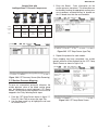
Sample Rack with
Intelligent Store™ Discus® Compressors
- 25° Suction
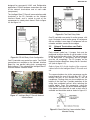
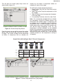
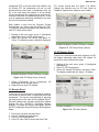
3. Enter the Board : Point information for the
suction pressure transducer. This information can
be found by locating the appropriate suction pressure transducer and determining its location on
the I/O board wired into the rack controller.
- 15° Suction
4DL3A150L-TSK
04I35625R
3DRHA100E-TFD
04I00300R
4DS3A220E-TSK
04I35631R
3DRHA100E-TFD
04I00439R
Address
Subnet: 15
Node: 2
Subnet: 15
Node: 5
Subnet: 15
Node: 4
Subnet: 15
Node: 3
Subnet: 15
Node: 1
Compressor
Name
RACK1COMP1
RACK1COMP2
RACK1COMP3
RACK2COMP1
RACK2COMP2
Comp1
Comp2
Comp3
(unloader)
Comp4
Comp5
(unloader)
Comp1
Comp2
(unloader)
Comp3
Stages
2DC3-050E-TFD
04I00435R
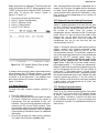
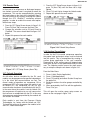
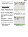
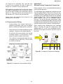
Figure 3.25 CST Setup Screen (Input Tab)
4. Repeat this process for each module.
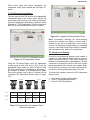
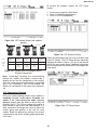
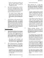
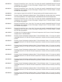
Once mapping has been completed, the suction
group’s pressure will be displayed on the CST Comp
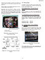
Status Screen as shown in figure 3.26.
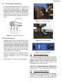
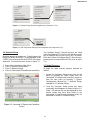
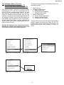
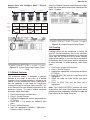
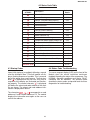
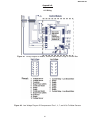
Figure 3.24 CST Summary Screen (After Renaming)
3.15 Suction Pressure Mapping
To serve as a convenient and quick reference, the
suction pressure value of the whole suction group
may be displayed on each individual CST Status
Screen. For this value to be displayed it must first be
mapped in the E2 by following these steps:
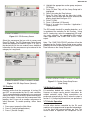
1. From the CST Setup Screen shown in figure 3.7,
Press F2 (Next Tab) to access the Input Tab.
2. Use the down arrow key to highlight the cell next
to Suction Pres In.
21
Figure 3.26 CST Comp Status Screen