1
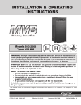
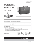
INSTALLATION & OPERATING
INSTRUCTIONS
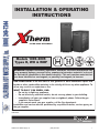
ULTRA HIGH EFFICIENCY
Models 1005–2005
Types H, WH & WHP
L
W
WARNING: Improper installation, adjustment, alteration, service or maintenance can
cause property damage, personal injury, exposure to hazardous materials* or loss of
life. Review the information in this manual carefully. *This unit contains materials that
have been identified as carcinogenic, or possibly carcinogenic, to humans.
FOR YOUR SAFETY: Do not store or use gasoline or other flammable vapors and
liquids or other combustible materials in the vicinity of this or any other appliance. To
do so may result in an explosion or fire.
WHAT TO DO IF YOU SMELL GAS:
• Do not try to light any appliance.
• Do not touch any electrical switch; do not use any phone in your building.
• Immediately call your gas supplier from a neighbor's phone. Follow the gas
supplier's instructions.
• If you cannot reach your gas supplier, call the fire department.
Installation and service must be performed by a qualified installer, service agency or
the gas supplier.
This manual should be maintained in legible condition and kept adjacent to the heater or in a safe place for future
reference.
CATALOG NO. 3400.55A
California Hot Water Supply, Inc.
Effective: 02-24-09
(800) 249-7244
Replaces: 09-24-08
P/N 241344 Rev. 2
1
Rev. 2 reflects the following: Changes to: Fig. 1, 2 and 3 on page 6; the Relief Valve Installation and Piping section on
page 14; Fig. 14–16 on page 16; Fig. 17 on page 17; Table I on page 18; step 6 of the Heater Sequence of Operation section on page 36; the Wiring Diagrams on pages 40 and 41. The addition of: A caution note to the Pool/Spa Water
Chemistry section on page 19; a wiring diagram note on the bottom of page 39.
California Hot Water Supply, Inc.
(800) 249-7244
2
CONTENTS
WARNINGS
Pay Attention to These Terms
BEFORE INSTALLATION
Product Receipt
Model Identification
Ratings and Certifications
Installations at Elevation
Component Locations
General Information
Time/Temperature Relationships
in Scalds
GENERAL SAFETY
INSTALLATION
Installation Codes
Equipment Base
Clearances
Combustion and Ventilation Air
Conventional Combustion Air Supply
Water Piping
Hydronic Heating
Gas Supply
Electrical Power Connections
Field Wiring Connection
Venting
Venting Installation Tips
Venting Configurations
Outdoor Installation
4
4
5
5
5
5
5
6
6
Controls
Heater Sequence of Operation
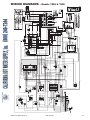
WIRING DIAGRAMS
Models 1005 & 1505
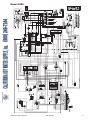
Model 2005
START-UP
Pre Start-up
Pre Start-up Check
Initial Start-up
Preparation
Start-Up
OPERATION
Lighting Instructions
To Turn Off Gas To Appliance
TROUBLESHOOTING
UDB Fault History
MAINTENANCE
Suggested Minimum
Maintenance Schedule
Preventive Maintenance
Schedule
APPENDIX
Inside Air Contamination
Important Instructions for the
Commonwealth of
Massachusetts
WARRANTIES
7
7
8
8
8
8
9
13
14
15
19
20
22
22
24
24
29
30
36
40
40
41
42
42
42
43
43
43
47
47
47
48
49
49
49
50
51
51
52
53
3
California Hot Water Supply, Inc.
(800) 249-7244
3
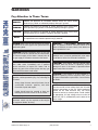
WARNINGS
Pay Attention to These Terms
DANGER:
Indicates the presence of immediate hazards which will cause severe
personal injury, death or substantial property damage if ignored.
WARNING:
Indicates the presence of hazards or unsafe practices which could cause
severe personal injury, death or substantial property damage if ignored.
CAUTION:
Indicates the presence of hazards or unsafe practices which could cause
minor personal injury or product or property damage if ignored.
NOTE:
Indicates special instructions on installation, operation, or maintenance which
are important but not related to personal injury hazards.
DANGER: Make sure the gas on which the heater
will operate is the same type as that specified on the
heater rating plate.
WARNING: Should overheating occur or the gas
supply valve fail to shut, do not turn off or disconnect
the electrical supply to the heater. Instead, shut off
the gas supply at a location external to the heater.
WARNING: Do not use this heater if any part has
been under water. Immediately call a qualified
service technician to inspect the heater and to
replace any part of the control system and any gas
control which has been under water.
WARNING: To minimize the possibility of improper
operation, serious personal injury, fire, or damage to
the heater:
•
•
Always keep the area around the heater free of
combustible materials, gasoline, and other
flammable liquids and vapors.
Heater should never be covered or have any
blockage to the flow of fresh air to the heater.
WARNING: Risk of electrical shock. More than one
disconnect switch may be required to de-energize
the equipment before servicing.
California Hot Water Supply, Inc.
WARNING - CALIFORNIA PROPOSITION
65: This product contains chemicals known to the
State of California to cause cancer, birth defects or
other reproductive harm.
CAUTION: If this heater is to be installed above
radiation level, it must be provided with a low water
cut-off device at the time of heater installation.
CAUTION: This heater requires forced water
circulation when the burner is operating. Severe
damage will occur if the heater is operated without
proper water flow circulation.
CAUTION: If this heater is to be installed in a
negative or positive pressure equipment room, there
are special installation requirements. Consult factory
for details.
NOTE: Minimum 18 AWG, 105°C, stranded wire
must be used for all low voltage (less than 30 volts)
external connections to the unit. Solid conductors
should not be used because they can cause
excessive tension on contact points. Install conduit
as appropriate. All high voltage wires must be the
same size (105°C, stranded wire) as the ones on the
unit or larger.
(800) 249-7244
4
BEFORE INSTALLATION
Raypak strongly recommends that this manual be reviewed thoroughly before installing your XTherm
heater. Please review the General Safety information
before installing the heater. Factory warranty does not
apply to heaters that have been improperly installed or
operated. (Refer to the warranty at the back of this
manual.) Installation and service must be performed
by a qualified installer, service agency or gas supplier.
If, after reviewing this manual, you still have questions
which this manual does not answer, please contact
your local Raypak representative or visit our website at
www.raypak.com.
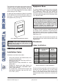
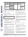
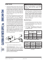
the upper rear jacket panel of the heater. The model
number will have the form H7-2005 or similar depending on the heater size and configuration. The letter(s)
in the first group of characters identifies the application
(H = Hydronic Heating, WH = Domestic Hot Water
(DHW), WHP = Water Heater for Pool Heating). The
number which follows identifies the firing mode (7 =
electronic modulation, 1 = On/Off). The second group
of characters identifies the size of the heater (four
numbers representing the approximate MBTUH input),
and, where applicable, a letter, indicating the manufacturing series.
Ratings and Certifications
Thank you for purchasing a Raypak product. We hope
you will be satisfied with the high quality and durability
of our equipment.
Standards:
Product Receipt
•
•
•
On receipt of your heater it is suggested that you visually check for external damage to the shipping crate. If
the crate is damaged, make a note to that effect on the
Bill of Lading when signing for the shipment. Next,
remove the heater from the shipping packaging.
Report any damage to the carrier immediately.
On occasion, items are shipped loose. Be sure that
you receive the correct number of packages as indicated on the Bill of Lading.
Claims for shortages and damages must be filed with
the carrier by consignee. Permission to return goods
must be received from the factory prior to shipping.
Goods returned to the factory without an authorized
Returned Goods Receipt number will not be accepted.
All returned goods are subject to a restocking charge.
When ordering parts, you must specify the model and
serial number of the heater. When ordering under warranty conditions, you must also specify the date of
installation.
Purchased parts are subject to replacement only
under the manufacturer’s warranty. Debits for defective replacement parts will not be accepted. Parts will
be replaced in kind only per Raypak’s standard warranties.
Model Identification
The model identification number and heater serial
number are found on the heater rating plate located on
California Hot Water Supply, Inc.
•
ANSI Z21.13 · CSA 4.9 - latest edition, Gas-Fired
Hot Water Boilers
CAN 3.1 - latest edition, Industrial and
Commercial Gas-Fired Package Boilers
ANSI Z21.10.3 · CSA 4.3 - latest edition, Gas Water Heaters
SCAQMD Rule 1146.2
All Raypak heaters are National Board Approved, and
design-certified and tested by the Canadian Standards
Association (CSA) for the U.S. and Canada. Each primary heat exchanger is constructed in accordance
with Section IV, and each secondary heat exchanger
in accordance with Section VIII, of the American
Society of Mechanical Engineers (ASME) Heater
Pressure Vessel Code and bears the applicable ASME
stamp. This heater also complies with the latest edition
of the ASHRAE 90.1 Standard.
WARNING: Altering any Raypak pressure vessel
by installing replacement heat exchangers, tube
bundle headers, or any ASME parts not
manufactured and/or approved by Raypak will
instantly void the ASME and CSA ratings of the
vessel and any Raypak warranty on the vessel.
Altering the ASME or CSA ratings of the vessel also
violates national, state, and local approval codes.
Installations at Elevation
Rated inputs are suitable for up to 4,500 ft elevation
without de-rating. Consult your local representative or
the factory for installations at altitudes over 4,500 ft
above sea level. No hardware changes are required to
the heaters for installations up to 10,000 ft (adjustments may be required).
(800) 249-7244
5
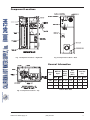
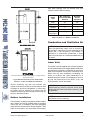
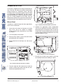
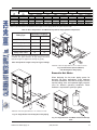
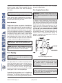
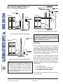
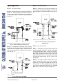
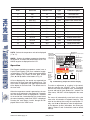
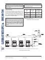
Component Locations
Fig. 1: Component Locations – Right Side
Fig. 3: Component Locations – Rear
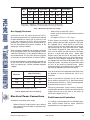
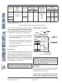
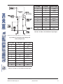
General Information
Model
No.
MBTUH
Input
Water
Conn.
(NPT)
Max. Min.
Gas
Conn.
(NPT)
N
P
Vent Size
(in.)
Flue Intake
1005
999
250
2-1/2
1-1/4
1
6
6
1505
1500
375
2-1/2
1-1/4
1
8
8
2005
1999
500
2-1/2
2
1
8
8
Table A: Basic Data
Fig. 2: Component Locations – Top
California Hot Water Supply, Inc.
(800) 249-7244
6
GENERAL SAFETY
To meet commercial hot water use needs, the high
limit safety control on this water heater will shut off the
main gas valve before the outlet temperature reaches
210°F. However, water temperatures over 125°F can
cause instant severe burns or death from scalds.
When supplying general purpose hot water, the recommended initial setting for the temperature control is
125°F.
Safety and energy conservation are factors to be considered when setting the water temperature on the
thermostat. The most energy-efficient operation will
result when the temperature setting is the lowest that
satisfies the needs of the application.
Water temperature over 125°F can
cause instant severe burns or death
from scalds.
Water temperature over 125°F can cause instant
severe burns or death from scalds. Children, disabled
and elderly are at highest risk of being scalded.
•
•
Children, disabled, and elderly are
at highest risk of being scalded.
See instruction manual before setting temperature at water heater.
Feel water before bathing or showering.
Temperature limiting valves are available.
Feel water before bathing or showering.
NOTE: When this water heater is supplying general
purpose hot water for use by individuals, a
thermostatically controlled mixing valve for reducing
point of use water temperature is recommended to
reduce the risk of scald injury. Contact a licensed
plumber or the local plumbing authority for further
information.
Temperature limiting valves are
available, see manual.
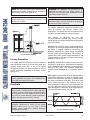
Time/Temperature
Relationships in Scalds
Maximum water temperatures occur just after the
heater’s burner has shut off. To determine the water
temperature being delivered, turn on a hot water
faucet and place a thermometer in the hot water
stream and read the thermometer.
This section applies to Hot Water Supply Boilers and
Hot Water Heaters ONLY. For sanitary rinse applications where outlet temperatures of 180°F to 195°F are
required, a boiler is recommended since the 210°F
limit on water heaters will NOT allow the heater to
maintain these desired sanitary rinse temperatures.
The following chart details the relationship of water
temperature and time with regard to scald injury and
may be used as a guide in determining the safest
water temperature for your applications.
Water
Temp.
Time to Produce Serious
Burn
120°F
More than 5 minutes
125°F
1-1/2 to 2 minutes
130°F
About 30 seconds
135°F
About 10 seconds
140°F
Less than 5 seconds
145°F
Less than 3 seconds
150°F
About 1-1/2 seconds
155°F
About 1 second
Table courtesy of The Shriners Burn Institute
Table B: Time to Produce Serious Burn
California Hot Water Supply, Inc.
(800) 249-7244
7
Equipment Base
The temperature of the water in the heater can be regulated by using the Raypak Modulating Temperature
Control. To comply with safety regulations, the control
is set at 120°F when shipped from the factory (Mode 3
default setting for Tank Target).
The heater should be mounted on a level, structurally
sound surface. The heater is approved for installation
on a combustible surface but must NEVER be
installed on carpeting. Gas-fueled equipment installed
in enclosed parking garages must be located at least
18 in. above the floor.
To adjust the water temperature, follow the instruction
for the operation of the control starting on page 31 of
this manual. The control is shown below for identification purposes only. (See Fig. 4.)
CAUTION: This heater should be located in an
area where water leakage will not result in damage
to the area adjacent to the appliances or to the
structure. When such locations cannot be avoided, it
is recommended that a suitable catch pan,
adequately drained, be installed under the
appliance. The pan must not restrict air flow.
In addition, the heater shall be installed such that the
gas ignition system components are protected from
water (dripping, spraying, rain, etc.) during appliance
operation or service (circulator replacement, control
replacement, etc.).
If the heater needs to be secured to the ground, use
the brackets that were used to bolt the heater to the
shipping pallet.
Fig. 4: Modulating Temperature Control
CAUTION: Hotter water increases the risk of
scalding! There is a hot water scald potential if the
thermostat is set too high.
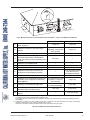
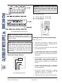
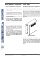
Clearances
Indoor Installations
INSTALLATION
Heater
Side
Installation Codes
Installations must follow these codes:
•
•
•
•
•
Local, state, provincial, and national codes, laws,
regulations and ordinances
National Fuel Gas Code, ANSI Z223.1/NFPA 54 –
latest edition (NFGC)
National Electrical Code, ANSI/NFPA 70 - latest
edition (NEC)
Standard for Controls and Safety Devices for
Automatically Fired Boilers, ANSI/ASME CSD-1,
(CSD-1) when required
For Canada only: CAN/CSA B149 Natural Gas
and Propane Installation Code and CSA C22.1
C.E.C. Part 1 (C22.1)
Minimum Clearance
from Combustible
Surfaces
Minimum
Service
Clearance
Floor*
0”
0”
Rear
12”
36”
Right Side
1”
24”
Left Side
1”
1”
Top
0”
10”
Front
Open
24”
Vent
1”
1”
*DO NOT install on carpeting.
Table C: Clearances – Indoor Installations
For ease of servicing, provide a minimum clearance of
at least 24 in. on the right side, 24 in. in front, at least
36 in. on the rear and 10 in. above the top of the
heater. This will allow the heater to be serviced in its
installed location without movement or removal of the
heater.
8
California Hot Water Supply, Inc.
(800) 249-7244
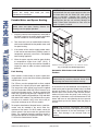
8
Roof water drainage must be diverted away from
heaters installed under overhangs.
Heater
Side
Min. Clearance
from Combustible
Surfaces
Minimum
Service
Clearance
Rear
12”
36”
Right Side
1”
24”
Left Side
1”
1”
Top
Unobstructed
10”
Vent
Termination
12”
12”
Table D: Clearances – Outdoor Installations
Combustion and Ventilation Air
NOTE: Use of this heater in construction areas
where fine particulate matter, such as concrete or
dry-wall dust, is present may result in damage to the
heater that is not covered by the warranty. If
operated in a construction environment, a clean
source of combustion air must be provided directly to
the heater.
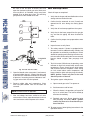
Indoor Units
This heater must be supplied with sufficient quantities
of non-contaminated air to support proper combustion
and equipment ventilation. Combustion air can be supplied via conventional means where combustion air is
drawn from the area immediately surrounding the
heater, or via direct vent, where combustion air is
drawn directly from outside. All installations must comply with the requirements of the NFGC (U.S.) and
B149 (Canada), and all local codes.
Venting not shown for clarity. Heater must be vented per instructions in this manual
Fig. 5: Minimum Clearances from Combustible
Surfaces – Indoor and Outdoor Installations
Service clearances less than the minimum may
require removal of the heater to service either the heat
exchanger or the burner components. In either case,
the heater must be installed in a manner that will
enable the heater to be serviced without removing any
structure around the heater.
CAUTION: Combustion air must not be
contaminated by corrosive chemical fumes which
can damage the heater and void the warranty. (See
the Appendix.)
NOTE: It is recommended that the intake vent be
insulated to minimize sweating.
Outdoor Installations
These heaters are design-certified for outdoor installation. Heaters must not be installed under an overhang
unless they are in accordance with local installation
codes and the requirements of the gas supplier. Three
sides must be open in the area under the overhang.
California Hot Water Supply, Inc.
(800) 249-7244
9
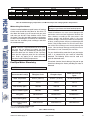
Fig. 6: Minimum Clearances from Vent/Air Inlet Terminations – Indoor and Outdoor Installations
1
1
2
t
TT
*
2
U.S. Installations
Canadian Installations
A
Clearance above grade, veranda, porch,
deck, or balcony
1 ft (30 cm)
1 ft (30 cm)
B
Clearance to window or door that may be
opened
4 ft (1.2m) below or to side
of opening; 1 foot (30 cm)
above opening
3 ft (91 cm)
C
Clearance to permanently closed window
*
*
D
Vertical clearance to ventilated soffit located
above the terminal within a horizontal distance of 2 ft (61cm) from the centerline of the
terminal
5 ft (1.5m)
*
E
Clearance to unventilated soffit
*
*
F
Clearance to outside corner
*
*
G
Clearance to inside corner
6 ft (1.83m)
*
H
Clearance to each side of center line extended above meter/regulator assembly
*
3 ft (91 cm) within a height
15 ft above the meter/regulator assembly
I
Clearance to service regulator vent outlet
*
6 ft (1.83m)
J
Clearance to non-mechanical air supply inlet
to building or the combustion air inlet to any
other appliance
4 ft (1.2m) below or to side
of opening; 1 ft (30 cm)
above opening
3 ft (91 cm)
K
Clearance to mechanical air supply inlet
3 ft (91 cm) above if within
10 ft (3m) horizontally
6 ft (1.83m)
L
Clearance above paved sidewalk or paved
driveway located on public property
7 ft (2.13m)
7 ft (2.13m) t
M
Clearance under veranda, porch, deck or
balcony
*
12 in. (30 cm) TT
In accordance with the current ANSI Z223.1/NFPA 54 National Fuel Gas Code
In accordance with the current CAN/CGA-B149 Installation Codes
Vent terminal shall not terminate directly above sidewalk or paved driveway located between 2 single family dwellings that serves
both dwellings
Permitted only if veranda, porch, deck, or balcony is fully open on a minimum of two sides beneath the floor and top of terminal and
underside of veranda, porch, deck or balcony is greater than 1 ft (30cm)
Clearances in accordance with local installation codes and the requirements of the gas supplier
Table E: Vent/Air Inlet Termination Clearances
California Hot Water Supply, Inc.
(800) 249-7244
10
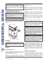
Combustion Air Filter
Inside Air Intake
Cover Panel
This heater is supplied with an integral combustion air
filter. This filter will reduce the amount of particulates
passed through the combustion system and heat
exchanger but will not protect against chemical inside
air contamination (See Appendix). The filter must be
checked periodically to verify that adequate combustion air is being supplied to the heater. See the
Maintenance section of this manual for information on
checking the filter and establishing service intervals.
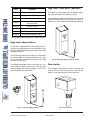
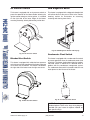
Direct Vent
If outside air is drawn through the intake pipe directly
to the unit for combustion:
Fig. 8: Install the Inside Air Intake Cover Panel
1. Convert the unit to draw air through an air intake
duct at the rear of the cabinet. As shipped,
XTherm heaters draw combustion air from inside
the cabinet.
6. Optional—For applications where condensation
may form on cold intake air ducting, install the condensate drip pan to the bottom of the air filter box
using the four screws provided (make sure the pan
is angled slightly downward toward the rear of the
heater as shown in Fig. 9).
2. Turn off all power to the heater.
3. Ensure that the heater is cool to the touch before
proceeding with the installation.
Condensate
Drip Pan
4. Remove both the left and right rear side access
panels.
Inside Air Intake
Opening
Fig. 9: Install the Condensate Drip Pan
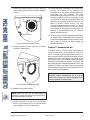
7. Remove the air intake cover panel by removing
the 5 phillips head screws holding it in place.
Fig. 7: Remove the Rear-side Access Panels
5. From the right-rear side access area, install the
inside air intake cover panel using the nine hexhead screws provided (see Fig. 8).
Air Intake
Cover Panel
Fig. 10: Remove the Air Intake Cover
California Hot Water Supply, Inc.
(800) 249-7244
11
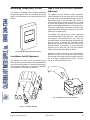
8. Remove the debris screen (or cover panel for
model 1005) by removing the six screws holding it
in place.
12. Provide adequate ventilation of the space occupied by the heater(s) by an opening(s) for
ventilation air at the highest practical point communicating with the outdoors. The total
cross-sectional area shall be at least 1 in.2 of free
area per 20,000 BTUH (111 mm2 per kW) of total
input rating of all equipment in the room when the
opening is communicating directly with the outdoors or through vertical duct(s). The total
cross-sectional area shall be at least 1 in.2 of free
area per 10,000 BTUH (222 mm2 per kW) of total
input rating of all equipment in the room when the
opening is communicating with the outdoors
through horizontal duct(s).
Debris Screen
13. In cold climates, and to mitigate potential freezeup, Raypak highly recommends the installation of
a motorized sealed damper to prevent the circulation of cold air through the heater during the
non-operating hours.
Fig. 11: Remove the Debris Screen
9. Install the intake air collar using the six screws
removed in step 8 above.
TruSeal™ Combustion Air
In addition to the 13 previous steps, combustion air
may be ducted directly to the heater by using PVC,
CPVC or sealed single-wall galvanized ducting. The
duct will attach directly to the field installed air collar
located on the rear of the heater, using three or four
sheet metal screws (not supplied) equally positioned
around the circumference of the duct. The screws and
duct connection point should be sealed with RTV (not
supplied). TruSeal is generally used when damaging
contaminants are present in the mechanical room. All
ducting must be self-supported.
Intake Air Collar
CAUTION: Use TruSeal combustion air if
damaging airborne contaminants are or may be
present in the heater area. See the Appendix of this
manual regarding air contamination.
Fig. 12: Install the Intake Air Collar
10. Replace all the access panels.
NOTE: Make sure that the air intake piping is
installed in a manner that allows full access to the air
filter without damage to the filter.
11. Install combustion air direct vent in accordance
with Fig. 27 (horizontal) or Fig. 28 (vertical) of this
manual (pages 27 and 28, respectively).
12
California Hot Water Supply, Inc.
(800) 249-7244
12
Conventional Combustion Air
Supply
U.S. Installations
All Air from Inside the Building
The confined space shall be provided with TWO permanent openings communicating directly with an
additional room(s) of sufficient volume so that the combined volume of all spaces meets the criteria for a
room large in comparison (NFGC). The total input of all
gas utilization equipment installed in the combined
space shall be considered in making this determination. Each opening shall have a minimum free area of
1 in.2 per 1,000 BTUH (2,225 mm2 per kW) of the total
input rating of all gas utilization equipment in the confined space, but not less than 100 in.2 (645 cm2). One
opening shall commence within 12 in. (305 mm) of the
top, and one opening shall commence within 12 in.
(305 mm) of the bottom of the enclosure. The minimum dimension of air openings shall be not less than
3 in. (76 mm) in any direction.
All Air from Outdoors
The confined space shall communicate with the outdoors in accordance with one of the methods below.
The minimum dimension of air openings shall not be
less than 3 in. (76 mm) in any direction. Where ducts
are used, they shall be of the same cross-sectional
area as the net free area of the openings to which they
connect.
1. Two permanent openings, one commencing
within 12 in. (305 mm) of the top, and one commencing within 12 in. (305 mm) of the bottom of
the enclosure, shall be provided. The openings
shall communicate directly, or by ducts, with the
outdoors or spaces (crawl or attic) that freely communicate with the outdoors.
a. Where directly communicating with the outdoors or where communicating to the
outdoors through vertical ducts, each opening shall have a minimum free area of 1 in.2
per 4,000 BTUH (550 mm2 per kW) of total
input rating of all equipment in the enclosure.
b. Where communicating with the outdoors
through horizontal ducts, each opening shall
have a minimum free area of 1 in.2 per 2,000
BTUH (1,100 mm2 per kW) of total input rating of all equipment in the enclosure.
California Hot Water Supply, Inc.
2. One permanent opening, commencing within 12
in. (305 mm) of the top of the enclosure, shall be
permitted where the equipment has clearances of
at least 1 in. (25 mm) from the sides and back and
6 in. (152 mm) from the front of the appliance. The
opening shall directly communicate with the outdoors or shall communicate through a vertical or
horizontal duct to the outdoors or spaces that
freely communicate with the outdoors, and shall
have a minimum free area of:
a. 1 in.2 per 3,000 BTUH (740 mm2 per kW) of
the total input rating of all equipment located in
the enclosure, and
b. Not less than the sum of the areas of all vent
connectors in the confined space.
WARNING: Do not use the “one permanent
opening” method if the equipment room is under
negative pressure conditions.
Canadian Installations
CAUTION: All combustion air must be drawn from
the air outside of the building; the mechanical equipment room must communicate directly with the
outdoors.
1. Ventilation of the space occupied by the heater
shall be provided by an opening(s) for ventilation
air at the highest practical point communicating
with the outdoors. The total cross-sectional area of
such an opening(s) shall be at least 10% of the
area required in 2. and 3. (below), but in no case
shall the cross-sectional area be less than 10 in.2
(65 cm2).
2. For heaters using a barometric damper in the vent
system there shall be a permanent air supply
opening(s) having a cross section area of not less
than 1 in.2 per 7,000 BTUH (320 mm2 per kW) up
to and including 1 million BTUH, plus 1 in.2 per
14,000 BTUH (160 mm2 per kW) in excess of 1
million BTUH. This opening(s) shall be either
located at or ducted to a point not more than 18 in.
(450 mm) nor less than 6 in. (152 mm) above the
floor level. The duct can also “goose neck” through
the roof. The duct is preferred to be straight down
and terminated 18 in. (450 mm) from the floor, but
not near piping. This air supply opening requirement shall be in addition to the air opening for
ventilation air required in 1. (above).
(800) 249-7244
13
Relief Valve Installation and Piping
WARNING: Care must be taken to ensure that the
equipment room is not under negative pressure
conditions.
WARNING: Pressure relief valve discharge piping
must be piped near the floor and close to a drain to
eliminate the potential of severe burns. Do not pipe
to any area where freezing could occur. Refer to
local codes.
3. For heaters not using a barometric damper in the
vent system, and when air supply is provided by
natural air flow from outdoors for a power burner
and there is no draft regulator, drafthood or similar
flue gas dilution device installed in the same
space, in addition to the opening for ventilation air
required in 1., there shall be a permanent air supply opening(s) having a total cross-sectional area
of not less than 1 in.2 for each 30,000 BTUH (74
mm2 per kW) of total rated input of the burner(s),
and the location of the opening(s) shall not interfere with the intended purpose of the opening(s)
for ventilation air referred to in 1. This opening(s)
can be ducted to a point not more than 18 in. (450
mm) nor less than 6 in. (152 mm) above the floor
level. The duct can also “goose neck” through the
roof. The duct is preferred to be straight down 18
in. (450 mm) from the floor, but not near piping.
The heater is supplied with a Section IV “HV” stamped
relief valve sized for the full input of the unit and a “UV”
stamped relief valve to protect the section VIII secondary heat exchanger. The relief valve assembly is
shipped loose and must be mounted directly to the
heater outlet. No valve shall be installed between the
heater and the relief valves. The relief valves shall be
mounted with their spindles vertical (see Fig. 1, 2 and
3 on page 6). Relief valve discharge piping shall provide no less than the cross sectional area of the relief
valve outlet and must be routed to a safe point of discharge. Installation must comply with all national, state
and local codes.
WARNING: The pressure relief valve must be
installed at the outlet of the heater. No valve is
permitted to be installed between the heater and the
relief valve.
4. Refer to the B149 Installation Code for additional
information.
Water Piping
Temperature & Pressure Gauge
General
The temperature and pressure gauge is shipped loose
for field installation and must be installed within 12
inches of the boiler outlet (if possible) in an easily
readable location. Installation must comply with ASME
Section IV as well as all applicable national, state and
local codes.
The heater should be located so that any water leaks
will not cause damage to the adjacent area or structures.
CAUTION: This heater must be installed with a
Primary-Secondary piping arrangement for the
integral pumping system to function properly.
Hydrostatic Test
Unlike many types of heaters, this heater does not require hydrostatic testing prior to being placed in
operation. The heat exchanger has already been factory-tested and is rated for 160 psi operating pressure.
However, Raypak does recommend hydrostatic testing of the piping connections to the heater and the rest
of the system prior to operation. This is particularly
true for hydronic systems using expensive glycolbased anti-freeze. Raypak recommends conducting
the hydrostatic test before connecting gas piping or
electrical supply.
NOTE: Minimum pipe size for the heater inlet/outlet
connections is dependent on the equivalent length of
piping between the load loop and the heater loop,
the operating conditions and the size of the heater.
See Table G on page 16.
14
California Hot Water Supply, Inc.
(800) 249-7244
14
Leaks must be repaired at once to prevent damage to
the heater. NEVER use petroleum-based stop-leak
compounds.
To perform hydrostatic test:
1. Connect fill water supply. With bleed valve open,
fill heater with water. When water flows from bleed
valve, shut off water. Close bleed valve. Carefully
fill the rest of the system, making sure to eliminate
any entrapped air by using high-point vents. Close
feed valve. Test at standard operating pressure for
at least 24 hours.
2. Make sure constant gauge pressure has been
maintained throughout test.
3. Check for leaks. Repair if found.
Raypak Integral Cold Water
Protection
Feedwater Regulator
Raypak recommends that a feedwater regulator be installed and set at 12 psi minimum pressure at the
highest point of the system. Install a check valve or
back flow device upstream of the regulator, with a
manual shut-off valve as required by local codes.
Piping
All high points should be vented. A heater installed
above radiation level must be provided with a low water cut-off device (sales order option F-10). This
heater, when used in connection with a refrigeration
system, must be installed so that the chilled medium is
piped in parallel with the heater with appropriate
valves to prevent the chilled medium from entering the
heater.
The piping system of a hot water heater connected to
heating coils located in air handling units where they
may be exposed to circulating refrigerated air, must be
equipped with flow control valves or other automatic
means to prevent gravity circulation of the heater
water during the cooling cycle. It is highly recommended that the piping be insulated.
CAUTION: Damage due to internal condensation
may occur if the heater inlet water temperature does
not exceed 50°F (22°C) within 7 minutes of start-up.
XTherm heaters are equipped with an integral cold
water protection system. Units equipped with the dual
injector pump system are designed to operate with
heater inlet water temperatures down to 50°F continuous. Under start up conditions the dual injector system
can operate with fluid temperatures down to 32°F.
Operation at lower temperatures will create unwarrantable damage to the injector pumps. XTherm WH
and WHP models equipped with single injector pumps
are designed for typical domestic hot water and commercial pool heating operating conditions respectively.
Contact your local representative or the factory for
applications assistance.
Air-Separation/Expansion Tank
All heaters should be equipped with a properly sized
expansion tank and air separator fitting as shown in
Fig. 13.
Hydronic Heating
Pump Selection
Fig. 13: Air-Separation/Expansion Tank
The heater is equipped with an integral cold water protection system that includes dual modulating injector
pumps to pull the required flow from the system loop
and a heater pump, sized by the factory, for the optimal ΔT across the primary heat exchanger. The
system is designed for continuous return temperatures
from 50°F to 180°F.
Three-Way Valves
WARNING: Three-way valves intended to regulate
system water temperatures by reducing flow in the
boiler should not be used.
XTherm heaters have an integral cold water protection
system to maintain required temperatures and flow
rates.
California Hot Water Supply, Inc.
(800) 249-7244
15
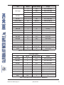
Model 2005
System
Model 1505
Model 1005
Minimum Pipe Size2
Supply Temp1
Supply Temp1
Minimum Pipe Size2
Return Temp Supply Temp1
Minimum Pipe Size2
(°F)
(°F)
<80' equiv. 80-200' equiv.
(°F)
<80' equiv. 80-200' equiv.
(°F)
<80' equiv. 80-200' equiv.
60
138
2"NPT
2 1/2"NPT
147
2"NPT
2 1/2"NPT
154
2"NPT
2 1/2"NPT
80
138
2"NPT
2 1/2"NPT
147
2"NPT
2 1/2"NPT
154
2 1/2"NPT
3"NPT
100
138
2 1/2"NPT
3"NPT
147
2 1/2"NPT
3"NPT
154
2 1/2"NPT
3"NPT
120
145
2 1/2"NPT
3"NPT
158
2 1/2"NPT
3"NPT
170
2 1/2"NPT
3"NPT
140
165
2 1/2"NPT
3"NPT
178
2 1/2"NPT
3"NPT
190
2 1/2"NPT
3"NPT
160
185
2 1/2"NPT
3"NPT
198
2 1/2"NPT
3"NPT
210
2 1/2"NPT
3"NPT
1
-Approximate high fire heater outlet temperature based on the standard heater pump and the recommended connecting pipe size.
2
-Minimum pipe size based on total equivalent feet of supply and return piping between the system loop and heater.
Table F: Boiler Temperatures and Minimum Pipe Size at Varying Return Temperatures
Equivalent Length (ft)
Fitting Type
2-1/2” NPT
3” NPT
90° Elbow (Std.)
8.5
9.4
90° Elbow (Long rad.)
3.5
3.6
45° Elbow
3.0
3.4
Gate Valve (Full open)
1.6
1.6
Swing Check Valve
22
25
Note: Equivalent lengths are calculated based on typical operating
conditions with typical Schedule 40 pipe fittings and valves.
Equivalent lengths are approximate and may vary greatly.
Table G: Equivalent Lengths of Pipe for Typical Fittings
*Maximum 4 times the pipe diameter or 12”, whichever is less.
Fig. 15: Dual Heaters (Reverse/Return)
with Primary/Secondary Piping
Domestic Hot Water
When designing the hot water piping system for
domestic hot water applications, water hardness
should be considered. See Table H on page 18 for the
required tubing sizes and expected supply temperatures for different operating conditions. Water
hardness is expressed in grains per gallon.
*Maximum 4 times the pipe diameter or 12”, whichever is less.
Fig. 14: Single Heater with Primary/Secondary Piping
Fig. 16: Single Domestic Hot Water Heater and Storage
Tank
California Hot Water Supply, Inc.
(800) 249-7244
16
NOTE: If local codes require a vacuum relief valve,
acquire one locally and install per valve
manufacturer’s instructions.
CAUTION: Power to the heater should be
interlocked with the main system pump to make sure
the heater does not fire without the main system
pump in operation. Improper flow control can
damage the heater. Uncontrolled flow (too high) or
restricted flow (too low) can seriously damage the
heater. Follow these instructions to make sure the
heater is properly installed.
Potable Water and Space Heating
CAUTION: When this heater is used for both
potable water and space heating, observe the
following to ensure proper operation.
1. All piping materials and components connected to
the water heater for the space heating application
shall be suitable for use with potable water.
2. Toxic chemicals, such as used for boiler treatment,
shall not be introduced into the potable water used
for space heating.
3. If the heater will be used to supply potable water,
it shall not be connected to any heating system or
components previously used with a non-potable
water heating appliance.
4. When the system requires water for space heating
at temperatures higher than 140°F (60°C), a
means such as a mixing valve shall be installed to
temper the water in order to reduce scald hazard
potential.
Fig. 17: Single Pool Heater Application
Automatic Chlorinators and Chemical
Feeders
Pool Heating
When a boiler or water heater is used in a pool heating application, ensure that all the following installation
requirements are met.
The XTherm must be equipped with a direct coupled
Cold Water Run injector pump for pool applications.
The integral wet rotor injector pump system supplied
with all H and model 1005 WH XTherm heaters must
not be used for pool service. The direct coupled Cold
Water Run injector pump package is optional on all H
and 1005 WH models and standard on 1505 and 2005
WH and all WHP models. The Cold Water Run system
must be set to maintain 120°F at the inlet to the primary heat exchanger on all XTherm models.
To complete installation of the pool heater, a pool thermostat must be installed in the return water line,
upstream of the heater. For WHP models, mount the
system sensor in the return water line, upstream of the
heater. The supplied electronic operating control is
configured to operate as the pool thermostat. See Fig.
17 for the thermostat/sensor location.
California Hot Water Supply, Inc.
*Maximum 4 times the pipe diameter or 12”, whichever is less.
CAUTION: Combustion air must not be
contaminated by corrosive chemical fumes which
can damage the heater and void the warranty.
All chemicals must be introduced and completely diluted into the pool or spa water before being circulated
through the heater. Do not place chlorine tablets or
bromine sticks in the skimmer. High chemical concentrations will result when the pump is not running (e.g.
overnight). Chlorinators must feed downstream of the
heater and have an anti-siphoning device to prevent
chemical back-up into the heater when the pump is
shut off.
NOTE: High chemical concentrates from feeders
and chlorinators that are out of adjustment will cause
very rapid corrosion of the heat exchanger in the
heater. Such damage is not covered under the
warranty.
(800) 249-7244
17
Model 1505
Model 2005
Model 1005
Tank
Minimum Tubing Size2
Minimum Tubing Size2
Minimum Tubing Size2
Return Temp Soft/Med Sup. Hard Sup.
Soft Sup.
Med Sup.
Hard Sup.
Soft/Med
1
Temp1 (°F)
Temp1 (°F)
Temp1 (°F) <80' equiv. 80-200' equiv. Temp1 (°F)
Temp1 (°F)
(°F)
<80' equiv. 80-200' equiv. Sup. Temp (°F) <80' equiv. 80-200' equiv.
60
138
135
2"
2 1/2"
150
145
143
2"
2 1/2"
154
2"
2 1/2"
80
138
135
2"
2 1/2"
150
145
143
2"
2 1/2"
154
2 1/2"
3"
100
138
135
2 1/2"
3"
150
145
143
2 1/2"
3"
154
2 1/2"
3"
120
146
146
2 1/2"
3"
150
146
146
2 1/2"
3"
155
2 1/2"
3"
130
156
156
2 1/2"
3"
156
156
156
2 1/2"
3"
165
2 1/2"
3"
140
166
166
2 1/2"
3"
166
166
166
2 1/2"
3"
175
2 1/2"
3"
1
-Approximate high fire heater outlet temperature based on the specified heater pump and the recommended minimum tubing size.
2
-Minimum tubing size based on total equivalent feet of supply and return piping between the tank and heater.
Table H: Hot Water Supply Temperatures and Minimum Pipe Size at Varying Return Temperatures
Winterizing Your Heater
Heaters installed outdoors as pool heaters in freezing
climate areas should be shut down for the winter. To
shut down the heater, turn off manual main gas valve
and main gas shut-off. Close isolation valves. Drain
the heater using the hose bibs located on the bottom
of both heat exchangers. Disconnect the condensate
hose from the secondary heat exchanger and drain
the condensate trap.
NOTE: There are 3 separate drains on the XTherm
that must ALL be drained to protect the heat
exchanger. These are accessible by removing the
lower front door from the heater for the 2 primary
drains and the right-rear panel for the secondary
drain. Drain any piping of all water that may
experience below-freezing temperatures.
NOTE: Chemical imbalance can cause severe
damage to your heater and associated equipment.
Chemical imbalance can cause severe damage to the
pool heater and associated equipment. Maintain the
water chemistry according to the chart below. If the
mineral content and dissolved solids in the water
become too high, scale forms inside the heat exchanger tubes, reducing heater efficiency and damaging the
heater. If the pH drops below 7.2, this will cause corrosion of the heat exchanger and severely damage the
heater. Heat exchanger damage resulting from chemical imbalance is not covered by the warranty.
For your health and the protection of your pool equipment, it is essential that your water be chemically
balanced. The following levels must be used as a
guide for balanced water.
Occasional chemical shock dosing of the pool or spa
should not damage the heater providing the water is
balanced.
Pool/Spa Water Chemistry
CAUTION: Corrosive water voids all warranties.
Recommended Level(s)
Fiberglass Pools
Fiberglass Spas
Other Pool and Spa
Types
Water Temperature
68-88°F (20-31°C)
89-104°F (31-40°C)
68-104°F (20-40°C)
pH
7.3-7.4
7.3-7.4
7.6-7.8
Total Alkalinity (ppm)
120-150
120-150
80-120
Calcium Hardness (ppm)
200-300
150-200
200-400
Salt (ppm)
140 Maximum**
140 Maximum**
140 Maximum**
Free Chlorine (ppm)*
2-3
2-3
2-3
Total Dissolved Solids
(ppm)
3000 Maximum
3000 Maximum
3000 Maximum
*Free Chlorine MUST NOT EXCEED 5 ppm!
**Not for use with salt water pools.
Table I: Water Chemistry
California Hot Water Supply, Inc.
(800) 249-7244
18
Automatic chemical dosing devices are usually more
efficient in heater water, unless controlled, they can
lead to excessive chlorine level which can damage
your heater.
of the heater gas controls. Refer to Table J on page 20
for maximum pipe lengths.
Gas Supply Connection
CAUTION: The XTherm is not for use with salt
water chlorinators—damage to heater may occur.
CAUTION: The heater must be disconnected from
the gas supply during any pressure testing of the gas
supply system at test pressures in excess of 1/2 psi
(3.45 kPa).
Further advice should be obtained from your pool or
spa builder, accredited pool shop, or chemical supplier for the correct levels for your water.
The heater must be isolated from the gas supply piping system by closing the upstream manual shut-off
valve during any pressure testing of the gas supply
piping system at test pressures equal to or less than
1/2 psi (3.45 kPa). Relieve test pressure in the gas
supply line prior to re-connecting the heater and its
manual shut-off valve to the gas supply line. FAILURE
TO FOLLOW THIS PROCEDURE MAY DAMAGE
THE GAS VALVE. Over-pressurized gas valves are
not covered by warranty. The heater and its gas connections shall be leak-tested before placing the
appliance in operation. Use soapy water for leak test.
DO NOT use an open flame.
Water Hardness
Raypak water heaters can operate lime/scale-free
using potable water with a hardness not exceeding 25
gpg for models 1005 and 1505, and not exceeding 16
gpg for model 2005. Proper operation is achieved by
setting the temperature rise/water flow per the guidelines in the installation instructions. If the hardness of
the water exceeds the maximum level of 25 gpg special measures must be taken to lower it. Water should
be softened to a hardness level no lower than 5 gpg.
Water softened as low as 0 to 1 grain per gallon may
be under-saturated with respect to calcium carbonate
resulting in water that is aggressive and corrosive.
NOTE: Soft = 0–4 grains per gallon; Medium = 5–15
grains per gallon; Hard = 16–25 grains per gallon.
NOTE: Failure of a heat exchanger due to lime
scale build-up on the heating surface, low pH or
other chemical imbalance is non-warrantable.
Gas Supply
DANGER: Make sure the gas on which the heater
will operate is the same type as specified on the
heater’s rating plate.
Fig. 18: Gas Supply Connection
CAUTION: Do not use Teflon tape on gas line pipe
thread. A pipe compound rated for use with natural
and propane gases is recommended. Apply
sparingly only on male pipe ends, leaving the two
end threads bare.
Gas piping must have a sediment trap ahead of the
heater gas controls, and a manual shut-off valve located outside the heater jacket. It is recommended
that a union be installed in the gas supply piping adjacent to the heater for servicing. The gas supply
pressure to the heater must not exceed 10.5 in. WC for
natural gas or 13.0 in. WC for propane gas.
CAUTION: Support gas supply piping with
hangers, not by the heater or its accessories. Make
sure the gas piping is protected from physical
damage and freezing, where required.
A pounds-to-inches regulator must be installed to
reduce the gas supply pressure if it is higher than
noted above. This regulator should be placed a minimum distance of 10 times the pipe diameter upstream
19
California Hot Water Supply, Inc.
(800) 249-7244
19
1-1/4” NPT
1-1/2” NPT
N
P
N
P
N
P
N
1005
35
55
35
90
125
300
300
1505
10
15
15
25
60
150
150
275
35
90
85
210
Model
No.
2” NPT
2005
2-1/2” NPT
P
Natural Gas – 1,000 BTU/ft3, 0.60 specific gravity at 0.5 in. WC pressure drop
Propane Gas – 2,500 BTU/ft3, 1.53 specific gravity at 0.6 in. WC pressure drop
Table J: Maximum Equivalent Pipe Length
Gas Supply Pressure
•
•
A minimum of 4.0 in. WC and a maximum of 10.5 in.
WC upstream gas pressure is required under load and
no-load conditions for natural gas. A minimum of 4.0
in. WC and a maximum of 13.0 in. WC is required for
propane gas. If upstream pressure exceeds these values, an intermediate gas pressure regulator, of the
lockup type, must be installed.
When connecting additional gas utilization equipment
to the gas piping system, the existing piping must be
checked to determine if it has adequate capacity for
the combined load. The gas valve pressure regulator
on the heater is nominally preset as noted in Table K.
During normal operation, carbon dioxide should be 8.5
to 9.0% at full fire for natural gas and between 9.5 and
10.0% for propane gas. Carbon monoxide should be
‹100ppm.
Model No.
Propane Gas
1005
-1.1
-0.6
1505
-1.6
0.3
2005
-1.8
-2.0
Power is connected to the heater via the rear wiring
box as shown at the top of Fig. 19. Main heater power
is connected to terminals 1, 2 and 3 and pump power
is connected to terminals 4, 5 and 6.
Field wiring connections such as sensors, interlocks,
enable/disable and alarm contacts are made at the low
voltage terminal strip at the front of the heater as
shown at the bottom of Fig. 19.
NOTE: Manifold pressures should be ±0.2 in. WC.
Table K: Manifold Gas Pressure Settings
Electrical Power Connections
Field-Connected Controllers
Installations must follow these codes:
•
National Electrical Code and any other national,
state, provincial or local codes or regulations having jurisdiction.
California Hot Water Supply, Inc.
XTherm heaters are wired for 120VAC single phase
power. Models 1005 and 1505, except WH 1505 models equipped with a heater pump for hard water,
require 15A service for the heater and 15A service for
the heater pump or a single 30A rated circuit. Model
1505 heaters equipped for hard water require 15A
service for the heater and 20A service for the heater
pump or a single 40A rated circuit. Model 2005
heaters require 20A service for the heater and 20A
service for the heater pump, or a single 40A service.
Consult the wiring diagram shipped with the heater.
Use appropriately sized wire as defined by NEC, CSA
and/or local codes. All primary wiring should be rated
for 125% of the minimum required service. Before
starting the heater, verify that the correct 120VAC voltage is being supplied to the heater and pump.
If any of the original wire supplied with the heater must
be replaced, it must be replaced with 105°C or its
equivalent.
Manifold Gas Pressure
(High Fire Values)
Natural Gas
•
Safety wiring must be NEC Class 1.
Heater must be electrically grounded as required
by the NEC.
In Canada, CSA C22. 1 C.E.C. Part 1.
It is strongly recommended that all individually-powered control modules and the heater should be
supplied from the same power source.
(800) 249-7244
20
WARNING: Using a multi-meter, check the
following voltages at the circuit breaker panel prior to
connecting any equipment. Make sure proper
polarity is followed and house ground is proven.
(See Fig. 20.)
Check the power source:
AC = 108 VAC Minimum, 132 VAC MAX
AB = 108 VAC Minimum, 132 VAC MAX
BC = <1 VAC Maximum
Fig. 19: Wiring Electrical Connections
NOTE: Field-supplied isolation relays should be
installed when field-connected controllers are
mounted more than a total of 50 equivalent feet (18
AWG) from heater.
Fig. 21: Multi-meter
Making the Electrical Connections
Refer to Fig. 19-22.
NOTE: Minimum 18 AWG, 105°C, stranded wire
must be used for all low voltage (less than 30 volts)
external connections to the unit. Solid conductors
should not be used because they can cause
excessive tension on contact points. Install conduit
as appropriate. All high voltage wires must be the
same size (105°C, stranded wire) as the ones on the
unit or larger.
1. Verify that circuit breaker is properly sized by
referring to heater rating plate. A dedicated circuit
breaker should be provided.
2. NOTE: Current draw noted on rating plate does
not include pump current.
3. Turn off all power to the heater. Verify that power
has been turned off by testing with a multi-meter
prior to working with any electrical connections or
components.
Check the Power Source
BLACK
4. Observe proper wire colors while making electrical connections. Many electronic controls are
polarity sensitive. Components damaged by improper electrical installation are not covered by
warranty.
CIRCUIT
BREAKER
WHITE
GREEN
5. Provide overload protection and a disconnect
means for equipment serviceability as required by
local and state code.
GROUND
A B
6. Install heater controls, thermostats, or building
management systems in accordance with the
applicable manufacturers’ instructions.
C
Fig. 20: Wiring Connections
7. Conduit should not be used as the earth ground.
21
California Hot Water Supply, Inc.
(800) 249-7244
21
temperature that avoids excessive condensate production in the vent.
NOTE: A grounding electrode conductor shall be
used to connect the equipment grounding
conductors, the equipment enclosures, and the
grounded service conductor to the grounding
electrode.
Category II – A heater which operates with a non-positive vent static pressure and with a vent gas
temperature that may cause excessive condensate
production in the vent.
Field Wiring Connection
Category III – A heater which operates with a positive
vent pressure and with a vent gas temperature that
avoids excessive condensate production in the vent.
CAUTION: Label all wires prior to disconnection
when servicing controls. Wiring errors can cause improper and dangerous operation. Verify proper
operation after servicing.
Category IV – A heater which operates with a positive
vent pressure and with a vent gas temperature that
may cause excessive condensate production in the
vent.
DANGER: SHOCK HAZARD
Make sure electrical power to the heater is disconnected to avoid potential serious injury or damage to
components.
See Table J for appliance category requirements.
NOTE: For additional information on appliance
categorization, see appropriate ANSI Z21 Standard
and the NFGC (U.S.), or B149 (Canada), or
applicable provisions of local building codes.
CAUTION: Condensate drains for the vent piping
are required for installations of the XTherm. Follow
vent manufacturer instructions for installation and
location of condensate drains in the vent.
Condensate drain trap must be primed with water to
prevent gas flue leak and must be routed to an
appropriate container for neutralization before disposal, as required by local codes.
WARNING: Contact the manufacturer of the vent
material if there is any question about the appliance
categorization and suitability of a vent material for
application on a Category III or IV vent system.
Using improper venting materials can result in
personal injury, death or property damage.
Fig. 22: Rear Wiring Location
Venting
Use only the special gas vent pipes listed for use with
Category IV gas burning heaters, such as the AL29-4C
stainless steel vents offered by Heat Fab Inc. (800772-0739), Protech System, Inc. (800-766-3473),
Z-Flex (800-654-5600) or American Metal Products
(800-423-4270). Pipe joints must be positively sealed.
Follow the vent manufacturer’s installation instructions
carefully.
CAUTION: Proper installation of flue venting is
critical for the safe and efficient operation of the
heater.
General
Appliance Categories
Heaters are divided into four categories based on the
pressure produced in the exhaust and the likelihood of
condensate production in the vent.
Category I – A heater which operates with a non-positive vent static pressure and with a vent gas
California Hot Water Supply, Inc.
Support of Vent Stack
The weight of the vent stack or chimney must not rest
on the heater vent connection. Support must be provided in compliance with applicable codes. The vent
should also be installed to maintain proper clearances
(800) 249-7244
22
Combustion
Air Supply
Exhaust
Configuration
Heater Venting
Category
Certified
Materials
IV
CAT IV
AL29-4C
Vertical
Venting
From Inside Building
(Non-Direct Venting) Horizontal Throughthe-Wall Venting
Vertical
Venting
From Outside Building
(Direct Venting)
Horizontal Throughthe-Wall Venting
Combustion Air
Inlet Material
Galvanized Steel
PVC
ABS
CPVC
Table L: Venting Category Requirements
from combustible materials. Use insulated vent pipe
spacers where the vent passes through combustible
roofs and walls.
8. Locate and guard vent termination to prevent accidental contact by people or pets.
9. DO NOT terminate vent in window well, stairwell,
alcove, courtyard or other recessed area.
Vent Terminal Location
1. Condensate can freeze on the vent cap. Frozen
condensate on the vent cap can result in a blocked
flue condition.
10. DO NOT terminate above any door, window, or
gravity air intake. Condensate can freeze, causing
ice formations.
NOTE: During winter months check the vent cap
and make sure no blockage occurs from build-up of
snow or ice.
11. Locate or guard vent to prevent condensate from
damaging exterior finishes. Use a rust-resistant
sheet metal backing plate against brick or masonry surfaces.
2. Give special attention to the location of the vent
termination to avoid possibility of property damage or personal injury.
12. DO NOT extend exposed vent pipe outside of
building beyond the minimum distance required
for the vent termination. Condensate could freeze
and block vent pipe.
3. Gases may form a white vapor plume in winter.
The plume could obstruct a window view if the termination is installed near windows.
4. Prevailing winds, in combination with below-freezing temperatures, can cause freezing of
condensate and water/ice build-up on buildings,
plants or roofs.
5. The bottom of the vent terminal and the air intake
shall be located at least 12 in. above grade, including normal snow line.
6. Un-insulated single-wall Category IV metal vent
pipe shall not be used outdoors in cold climates for
venting gas-fired equipment without insulation.
7. Through-the-wall vents for Category IV appliances shall not terminate over public walkways or
over an area where condensate or vapor could
create a nuisance or hazard or could be detrimental to the operation of regulators, relief valves, or
other equipment.
California Hot Water Supply, Inc.
U.S. Installations
Refer to the latest edition of the National Fuel Gas
Code.
Vent termination requirements are as follows:
1. Vent must terminate at least 4 ft below or 4 ft horizontally from any door, window or gravity air inlet
to the building.
2. The vent must not be less than 7 ft above grade
when located adjacent to public walkways.
3. Terminate vent at least 3 ft above any forced air
inlet located within 10 ft.
4. Vent must terminate at least 4 ft horizontally, and
in no case above or below unless 4 ft horizontal
distance is maintained, from electric meters, gas
meters, regulators, and relief equipment.
(800) 249-7244
23
5. Terminate vent at least 6 ft away from adjacent
walls.
6. DO NOT terminate vent closer than 5 ft below roof
overhang.
7. The vent terminal requires a 12 in. vent terminal
clearance from the wall.
8. Terminate vent at least 1 ft above grade, including
normal snow line.
9. Multiple direct vent installations require a 4 ft
clearance between the ends of vent caps located
on the same horizontal plane.
8. Underneath a verandah, porch or deck, unless the
verandah, porch or deck is fully open on a minimum of two sides beneath the floor, and the
distance between the top of the vent termination
and the underside of the verandah, porch or deck
is greater than 1 ft (305 mm).
Venting Installation Tips
Support piping:
•
•
•
horizontal runs—at least every 5 ft (1.5m)
vertical runs—use braces
under or near elbows
WARNING: Examine the venting system at least
once a year. Check all joints and vent pipe
connections for tightness, corrosion or deterioration.
WARNING: The Commonwealth of Massachusetts
requires that sidewall vented heaters, installed in
every dwelling, building or structure used in whole or
in part for residential purposes, be installed using
special provisions as outlined on page 52 of this
manual.
Venting Configurations
Refer to latest edition of the B149 Installation Code.
For heaters connected to gas vents or chimneys, vent
installations shall be in accordance with the NFGC
(U.S.), or B149 (Canada), or applicable provisions of
local building codes.
A vent shall not terminate:
Vertical Venting (Category IV)
Canadian Installations
1. Directly above a paved sidewalk or driveway
which is located between two single-family dwellings and serves both dwellings.
2. Less than 7 ft (2.13 m) above a paved sidewalk or
paved driveway located on public property.
3. Within 6 ft (1.8 m) of a mechanical air supply inlet
to any building.
4. Above a meter/regulator assembly within 3 ft (915
mm) horizontally of the vertical centre-line of the
regulator.
5. Within 6 ft (1.8 m) of any gas service regulator
vent outlet.
6. Less than 1 ft (305 mm) above grade level.
7. Within 3 ft (915 mm) of a window or door which
can be opened in any building, any non-mechanical air supply inlet to any building or the
combustion air inlet of any other appliance.
California Hot Water Supply, Inc.
CAUTION: This venting system requires the
installation of a condensate drain in the vent piping
per the vent manufacturer’s instructions. Failure to
install a condensate drain in the venting system will
void all warranties on this heater.
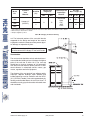
Installation
The maximum and minimum venting length for this
Category IV appliance shall be determined per the
NFGC (U.S.) or B149 (Canada).
The diameter of vent flue pipe should be sized according to the NFGC (U.S.) and Appendix B of B149
(Canada). The minimum flue pipe diameter for conventional venting using Category IV, stainless steel
AL29-4C vent is: 6 in. (152mm) for Model 1005 and 8
in. (203mm) for Models 1505 and 2005.
The connection from the appliance vent to the stack
must be as direct as possible and shall be the same diameter as the vent outlet. The horizontal breaching of
a vent must have an upward slope of not less than 1/4
inch per linear foot from the heater to the vent termi-
(800) 249-7244
24
Model
No.
Certified
Vent
Material
1005
1505
Vent Size
(in.)
Vertical Vent
Height1 (ft)
Min.
Max.
6
Category IV
(AL29-4C)
0
75
8
2005
Combustion Air
Intake Pipe
Material
Galvanized
Steel,
PVC,
ABS,
CPVC
Air Inlet
Max. Length* (ft)
6” Ø
8” Ø
45
100**
45
10” Ø
85**
1 Vent lengths are based on a lateral length of 2 ft. Refer to the latest edition of the NFGC for further details.
* Subtract 10 ft per elbow. Max. 4 elbows.
** Adapters supplied by others.
Table M: Category IV Vertical Venting
nal. The horizontal portions of the vent shall also be
supported for the design and weight of the material
employed to maintain clearances and to prevent physical damage or separation of joints.
NOTE: A vent adapter (field-supplied) may be required to connect the Category IV vent to the heater.
Termination
The vent terminal should be vertical and should terminate outside the building at least 2 ft above the highest
point of the roof that is within 10 ft. The vent cap
should have a minimum clearance of 4 ft horizontally
from and in no case above or below (unless a 4 ft horizontal distance is maintained) electric meters, gas
meters, regulators and relief equipment.
The distance of the vent terminal from adjacent public
walkways, adjacent buildings, open windows and
building openings must be consistent with the NFGC
(U.S.) or B149 (Canada). Gas vents supported only by
flashing and extended above the roof more than 5 ft
should be securely guyed or braced to withstand snow
and wind loads.
Fig. 23: Vertical Venting
California Hot Water Supply, Inc.
(800) 249-7244
25
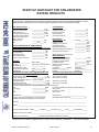
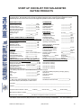
START-UP CHECKLIST FOR FAN-ASSISTED
RAYPAK PRODUCTS
This start-up checklist is to be completely filled out by the service technician starting up the Raypak Boiler or Heater
for the first time. All information may be used for warranty purposes and to ensure that the installation is correct.
Additionally this form will be used to record all equipment operation functions and required settings.
GAS SUPPLY DATA
Regulator Model & Size
Gas Line Size (in room)
Length of Gas Line
Low Gas Pressure Setting
High Gas Pressure Setting
Gas Shut-Off Valve Type
( Ball, Lube cock)
Sediment Trap
Port
CLEARANCES
_________ / ______CFH
________________In. NPT
________________Eq Ft
________________In. WC
________________In. WC
________________
Front Clearance
Right Side Clearance
Left Side Clearance
Rear Clearance
Overhead Clearance
ELECTRICAL
________________Y/N
_______Std______Full
VISUAL INSPECTION OF COMPONENTS
Verify inspection was done and condition of components are in
good working order with a “yes”
Wiring Harness
_________________ Y/N
Burner/s (flame)
_________________ Y/N
Refractory (visual)
_________________ Y/N
Remote flame sense
_________________ Y/N
Covers in place for outdoor
_________________ Y/N
VENTING
Vent Size: _____________
Category: _________
Vent Material:
Vent Termination Type:
Combustion Air Openings:
Ventilation air
_______________In.
_______________In.
_______________In.
_______________In.
_______________In.
Stack Height:_______
sketch vent on reverse side ***
__________________
__________________
Low __________ in2
High __________ in2
EMISSIONS SETTINGS AND TEST INFORMATION
(AT FULL FIRE)
Voltage Supply (VAC)
Voltage -24 VAC
Voltage Com to Ground
Hot Surface Igniter
Auto High Limit Setting
Manual Reset High Limit Setting
Operating Control Setting
No Load______ Load_____
_______________VAC
_______________VAC
_______________Ohms
_______________deg F
_______________deg F
_______________deg F
Sketch plumbing on reverse side
WATER SUPPLY
Flow Rate in GPM or Delta T
Measure flow rate at full fire
Pump Economaster setting
Low Water Cutoff
Number of Tanks and Size
Plumbing Size
Pump Size: _________(boiler)
Impeller trim____________
Louvers __________________
_______________If Avail
_______________Minutes
_______________Test
Qty____ _______Gallons
_______________
Pump HP: ______
Pump Model___________
Screens________________
Nominal Factory Recommended Settings
Blower Pressure Setting
_________________In. WC
See manual or card tag
Supply Gas Pressure
_________________In. WC
See manual or card tag
Verify stable pressure static & dynamic condition
Pilot Gas Pressure
_________________In. WC
See manual or card tag
Manifold Gas Pressure
_________________In. WC
See manual or card tag
Tracking Pressure (clean filter) _________________In. WC
The following measurements must be obtained with a Combustion Analyzer.
NOX
_________________PPM
Less than 20 PPM (If required by Certifying Agency)
Free Oxygen
_________________%
See manual
CO
_________________PPM
Less than 150 PPM
CO2
_________________%
See manual
Model Number: ______________________________
*** Note: draw venting with details, such as extractors,
barometric dampers, blast dampers or draft inducers
Serial Number: _______________________________
Site Altitude Above Sea Level __________________Ft.
Job Name _______________________________________________________________________________________
Address _________________________________________________________________________________________
Physical Location of Boiler: Indoors______; Outdoors______; Ground Level______; Roof______; Below Grade______
Mechanical Contractor / Installer _______________________________________________________________________
Date and Time of Start-up _____________Print Name and Signature of Start-up Technician_________________________
Information must be faxed to: (805) 278-5471 in order to ensure warranty consideration
California Hot Water Supply, Inc.
(800) 249-7244
Attn: Service Manager
26
Horizontal Through-the-Wall and
Direct Venting (Category IV)
Fig. 27: Horizontal Through-the-Wall Direct Venting
Fig. 25: Horizontal Through-the-Wall Venting
CAUTION: This venting system requires the
installation of a condensate drain in the vent piping
per the vent manufacturer’s instructions. Failure to
install a condensate drain in the venting system will
void all warranties on this heater.
Installation
These installations utilize the heater-mounted blower
to vent the combustion products to the outdoors.
Combustion air is taken from inside the room and the
vent is installed horizontally through the wall to the outdoors. Adequate combustion and ventilation air must
be supplied to the equipment room in accordance with
the NFGC (U.S.) or B149 (Canada).
Fig. 26: Alt. Horizontal Through-the-Wall Venting
NOTE: While a drain connection is required in the
vent of all XTherm installations, the drain can be accomplished in several different ways. The figures in
this manual show the drain in a vent tee, however,
this can also be accomplished using an inline collector for condensing stacks or an inline vertical or
horizontal collector available from several of the
listed vent manufacturers.
The total length of the horizontal through-the-wall flue
system should not exceed 75 equivalent ft in length. If
horizontal run exceeds 75 equivalent ft, an appropriately sized variable-speed extractor must be used.
Each elbow used is equal to 10 ft of straight pipe. This
will allow installation in one of the four following
arrangements:
•
•
•
•
75’ of
65’ of
55’ of
45’ of
straight
straight
straight
straight
flue pipe
flue pipe and one elbow
flue pipe and two elbows
pipe and three elbows
The vent cap is not considered in the overall length of
the venting system.
California Hot Water Supply, Inc.
(800) 249-7244
27
Model
No.
Certified
Vent
Material
Vent Size
(in.)
1005
Horizontal Vent
Length (ft)
Min.
Max.
Combustion Air
Intake Pipe
Material
0
6” Ø
8” Ø
45
100**
Galvanized
Steel,
PVC,
ABS,
CPVC
6
Category IV
(AL29-4C)
Air Inlet
Max. Length* (ft)
75
1505
8
45
10” Ø
85**
2005
* Subtract 10 ft per elbow. Max. 4 elbows.
** Adapters supplied by others.
Table O: Category IV Horizontal Vent & Horizontal Direct Vent
The vent must be installed to prevent flue gas leakage.
Care must be taken during assembly to ensure that all
joints are sealed properly and are airtight. The vent
must be installed to prevent the potential accumulation
of condensate in the vent pipes. It is required that:
Direct Vent—Vertical
1. The vent must be installed with a condensate
drain located in proximity to the heater as directed
by the vent manufacturer.
2. The vent must be installed with a slight upward
slope of not less than 1/4 inch per foot of horizontal run to the vent terminal.
3. The vent must be insulated through the length of
the horizontal run.
Termination
The flue direct vent cap MUST be mounted on the exterior of the building. The direct vent cap cannot be
installed in a well or below grade. The direct vent cap
must be installed at least 1 ft above ground level and
above normal snow levels. The Raypak-approved
stainless steel flue direct vent cap must be used (sales
order option D-15). The vent terminal must be located
NO CLOSER than 12” off the wall.
WARNING: No substitutions of flue pipe or vent
cap material are allowed. Such substitutions would
jeopardize the safety and health of inhabitants.
Fig. 28: Direct Vent - Vertical
CAUTION: This venting system requires the
installation of a condensate drain in the vent piping
per the vent manufacturer’s instructions. Failure to
install a condensate drain in the venting system will
void all warranties on this heater.
Installation
These installations utilize the heater-mounted blower
to draw combustion air from outdoors and vent combustion products to the outdoors.
The total length of air supply pipe cannot exceed the
distances listed in Tables M and O. Each elbow used
is equal to 10 ft of straight pipe. This will allow installa-
California Hot Water Supply, Inc.
(800) 249-7244
28
tion in any arrangement that does not exceed the
lengths shown in Tables M and O. The vent cap is not
considered in the overall length of the venting system.
Care must be taken during assembly that all joints are
sealed properly and are airtight.
The vent must be installed to prevent the potential accumulation of condensate in the vent pipes. It is
required that:
1. The vent must be installed with a condensate
drain located in proximity to the heater as directed
by the vent manufacturer.
2. The vent must be installed with a slight upward
slope of not more than 1/4 inch per foot of horizontal run to the vent terminal.
3. The vent must be insulated through the length of
the horizontal run.
Termination
The vent cap MUST be mounted on the exterior of the
building. The vent cap cannot be installed in a well or
below grade. The vent cap must be installed at least 1
ft above ground level and above normal snow levels.
The vent cap MUST NOT be installed with any combustion air inlet directly above a vent cap. This vertical
spacing would allow the flue products from the vent
cap to be pulled into the combustion air intake installed
above.
This type of installation can cause non-warrantable
problems with components and poor operation of the
heater due to the recirculation of flue products. Multiple vent caps installed in the same horizontal plane
must have a 4 ft clearance from the side of one vent
cap to the side of the adjacent vent cap(s).
Combustion air supplied from outdoors must be free of
particulate and chemical contaminants. To avoid a
blocked flue condition, keep the vent cap clear of
snow, ice, leaves, debris, etc.
WARNING: No substitutions of flue pipe or vent
cap material are allowed. Such substitutions would
jeopardize the safety and health of inhabitants.
The stainless steel flue direct vent cap must be furnished by the heater manufacturer in accordance with
its listing (sales order option D-15).
California Hot Water Supply, Inc.
Outdoor Installation
XTherm heaters are certified for outdoor operation in
non-freezing conditions only. Freezing conditions may
cause condensate to freeze in the condensate drain
line and trap causing the unit to shut down from a
blocked condensate drain. Additionally, components of
the condensate management system may be damaged by the ice formation. Units installed in freezing
climates for seasonal use must be winterized to avoid
freeze damage to the heater.
Outdoor models must be vented with listed vent material per the following instructions and installed with the
optional factory-supplied outdoor vent kit. A special
vent cap is provided in accordance with CSA requirements. It must be installed directly on the vent pipe as
illustrated in Fig. 29 on page 30.
Care must be taken when locating the heater outdoors, because the flue gases discharged from the
vent cap can condense as they leave the cap.
Improper location can result in damage to adjacent
structures or building finish. For maximum efficiency
and safety, the following precautions must be
observed:
1.
Outdoor models must be installed outdoors and
must use the outdoor vent cap and air intake hood
available from the manufacturer (sales order
option D-11).
2.
Periodically check venting system. The heater’s
venting areas must never be obstructed in any
way and minimum clearances must be observed
to prevent restriction of combustion and ventilation
air. Keep area clear and free of combustible and
flammable materials.
3.
Do not locate adjacent to any window, door, walkway, or gravity air intake. The vent must be
located a minimum of 4 ft horizontally from such
areas.
4.
Install above grade level and above normal snow
levels.
5.
Vent terminal must be at least 3 ft above any
forced air inlet located within 10 ft.
6.
Adjacent brick or masonry surfaces must be protected with a rust-resistant sheet metal plate.
(800) 249-7244
29
NOTE: The vent cap and air intake hood must be
furnished by the heater manufacturer in accordance
with its listing (sales order option D-11).
CAUTION: This appliance has provisions to be
connected to more than one supply source. To
reduce the risk of electric shock, disconnect all such
connections before servicing.
NOTE: Condensate can freeze on the vent cap.
Frozen condensate on the vent cap can result in a
blocked flue condition.
CAUTION: Risk of electric shock: More than one
disconnect switch may be required to de-energize
the equipment before servicing.
The Raypak modulating temperature control is provided to maintain the desired system water
temperature. The control has various modes of operation which are described on the following pages.
The XTherm is designed for use with
Primary/Secondary pumping only, utilizing integral
injector pumps to maintain proper flows and temperatures in the heater.
Freeze Protection
Set-point: for a specific system supply temperature,
the system return (target) temperature settings, where
the sensor is located, should be reduced by the
difference between the system supply temperature
and the system return temperature. For example, to
maintain near 160ºF system supply temperature, and
if the system ΔT is 10ºF, then the system return (target)
set-point is 160-10=150ºF.
The Raypak electronic temperature control includes a
freeze protection feature. In the event the water temperature drops below 40°F at any of the heater
temperature sensors, the pump is turned on and will
remain on until the temperature at all heater sensors
rises to 45°F.
Deadband: Deadband is a band of temperature sensing where no action occurs. All temperature controllers
have a deadband and the purpose is to prevent shortcycling of the heater. The on-board temperature
controller has a deadband of 2ºF around the differential.
Fig. 29: Outdoor Venting
Differential: A heat source must be operated with a
temperature differential in order to prevent shortcycling. The temperature differential is divided around
the “target” temperature or set-point. The Call For Heat
(CFH) contact will close in the controller when the
water temperature is below the target temperature by
1/2 of the differential setting, and will open when the
water temperature is above the target temperature by
1/2 of the differential setting. See Fig. 30.
WARNING: Do not install the heater outdoors if
freezing conditions are typical. The condensate will
freeze and back up the flue system.
Controls
WARNING: Installation, adjustment and service of
heater controls, including timing of various operating
functions, must be performed by a qualified installer,
service agency or the gas supplier. Failure to do so
may result in control damage, heater malfunction,
property damage, personal injury, or death.
WARNING: Turn off the power to the heater before
installation, adjustment or service of any heater
controls. Failure to do so may result in board
damage, heater malfunction, property damage,
personal injury, or death.
Fig. 30: Differential Graph
30
California Hot Water Supply, Inc.
(800) 249-7244
30
Operating Modes
Mode 4 – Not recommended.
Mode 1 – Not recommended.
Mode 5 – Outdoor reset using primary/secondary piping. The heater is operated as in Mode 2. However, the
target temperature is based on outdoor reset. See Fig.
33.
Mode 2 – Setpoint operation using primary/secondary
piping. The control operates the heater to satisfy a
remote system sensor. The heater is turned off based
on boiler max and boiler differential (factory default).
See Fig. 31.
MODULATING
MODULATING
*
*Maximum 4 times the pipe diameter or 12”, whichever is less.
*
Fig. 33: Mode 5 Primary/Secondary Piping with
Outdoor Reset
*Maximum 4 times the pipe diameter or 12”, whichever is less.
Fig. 31: Mode 2 Primary/Secondary Piping
Mode 6 – Not recommended.
Mode 3 – Dedicated DHW operation using UniTemp
80 piping. A call for heat is determined by the DHW
sensor and the DHW boiler target. The heater outlet
water is also controlled to the boiler target temperature. See Fig. 32.
Mode 7 – Designed for an external input signal with
primary/secondary piping. The external input signal
can be provided from a BMS, an EMS or a sequencing control. The external input signal changes the
boiler target according to a linear scale. The control
operates the boiler burner to maintain the boiler target
at the remote system sensor. See Fig. 34 on the following page.
MODULATING
Mode 8 – This mode is used for remote control of the
heater. The Boil Max setting is the heater shutdown
temperature. The heater is enabled with a control signal ≥ 0.5 VDC. 0.5 VDC corresponds to minimum fire
an 10 VDC corresponds to 100% firing rate. The BOIL
MAX setting is the heater shutdown temperature.
*Some models.
Fig. 32: Mode 3 Dedicated DHW
31
California Hot Water Supply, Inc.
(800) 249-7244
31
MODULATING
2-10 VDC
4-20 mA*
Boiler Target
0
0
--- (OFF)
1
2
--- (OFF)
2
4
50°F
3
6
71.3°F
4
8
92.5°F
5
10
113.8°F
6
12
135°F
7
14
156.3°F
8
16
177.5°F
9
18
198.8°F
10
20
220°F
*Requires a 500Ω resistor.
Table Q: 2-10 VDC or 4-20 mA External Input Signal
*
*Maximum 4 times the pipe diameter or 12”, whichever is less.
Fig. 34: Mode 7 Primary/Secondary Piping with
External Target Temp
0-10 VDC
0-20 mA*
Boiler Target
0
0
--- (OFF)
1
2
50°F
2
4
68.9°F
3
6
87.8°F
4
8
106.7°F
5
10
125.6°F
6
12
144.1°F
7
14
163.3°F
8
16
182.2°F
9
18
201.1°F
10
20
220°F
*Requires a 500Ω resistor.
Table P: 0-10 VDC or 0-20 mA External Input Signal
California Hot Water Supply, Inc.
(800) 249-7244
32
Item
Modes
Default Setting
Range
1, 2
160°F
OFF, 70 to 220°F
3
160°F
OFF, 70 to 190°F
4, 5, 6, 7
180°F
OFF, 70 to 220°F
1, 2, 4, 5, 6, 7, 8
200°F
OFF, 120 to 225°F
3
180°F
OFF, 120 to 190°F
Boil Min
1, 2, 3, 4, 5, 6, 7
150°F
OFF, 80 to 180°F
‘Burner’ Delay
All
0:00 min
0:00 to 3:00 min
Boil Mass
All
1 (Low)
1 (Low), 2 (Med), 3 (High)
Diff
1, 2, 3, 4, 5, 6, 7
Auto
Auto, 2 to 42°F
DHW Target
3
120°F
OFF, 70 to 190°F
DHW Diff
3
5°F
2 to 10°F
‘Pump’ Dly
All
3:00 min
OFF, 0:20 to 9:55 min, ON
Outdr Start
4, 5
70°F
35 to 85°F
Outdr Design
4, 5
-10°F
-60 to 32°F
Boil Start
4, 5
135°F
35 to 150°F
Boil Dsgn
4, 5
180°F
120 to 220°F
WWSD
4, 5
70°F
35 to 100°F
Units
All
°F
°F or °C
Mode
N/A
2
1, 2, 3, 4, 5, 6, 7, 8
External Input Signal
6, 7
2 to 10 VDC
2 to 10 VDC or 0 to 10 VDC
Offset
6, 7
0°F
-10°F to 10°F
Boil Target
Boil Max
Table R: Temperature Control Default Setpoints—H7 & WH7 Models
Pool Heater (WHP)
Item
Modes
Default Setting
Range
Boil Target
2
78°F
OFF, 45 to 106°F
Boil Max
2
86°F
OFF, 70 to 106°F
Boil Min
2
70°F
OFF, 45 to 106°F
‘Burner’ Delay
All
0:00 min
0:00 to 3:00 min
Boil Mass
All
1 (Low)
1 (Low), 2 (Med), 3 (High)
Diff
2
1°F
1 to 3°F
‘Pump’ Dly
All
3:00 min
OFF, 0:20 to 9:55 min, ON
Units
All
°F
°F or °C
Mode
N/A
2
2
Table S: Temperature Control Default Setpoints—WHP Models
California Hot Water Supply, Inc.
(800) 249-7244
33
Definitions
NOTE: The defined terms are not active in all
modes of control operation.
% OUT - Current percent modulation rate of heater.
BOIL DSGN - Design boiler water temperature used in
heat loss calculations.
BOIL MASS - This setting allows adjustment in the
field for high or low thermal masses; High thermal
mass (setting=3) provides slower reaction, lower thermal mass (setting=1) provides faster reaction.
BOIL MAX - Highest outlet water temperature that the
control is allowed to use as a target temperature.
BOIL MIN - Lowest outlet water temperature that the
control is allowed to use as a target temperature.
BOIL ON - Accumulated runtime of heater (up to 999
hours, then resets to 0).
BOIL OUT - Actual heater outlet water temperature.
0-10VDC or 0-20 mA external input signal – When
the 0-10VDC signal is selected, an input voltage of 1
VDC corresponds to a boiler target temperature of
50°F (10°C). An input voltage of 10 VDC corresponds
to a boiler target temperature of 220°F (104°C). As the
voltage varies between 1 VDC and 10 VDC, the boiler
target temperature varies linearly between 50°F
(10°C) and 220°F (104°C). If a voltage below 0.5 VDC
is received, the boiler target temperature is displayed
as “– – –” indicating that there is no longer an internal
heat demand. A 0-20 mA signal can be converted to a
0-10 VDC signal by installing a 500 Ω resistor on the
external input signal device’s terminals.
2-10VDC or 4-20 mA external input signal – When
the 2-10VDC signal is selected, an input voltage of 2
VDC corresponds to a boiler target temperature of
50°F (10°C). An input voltage of 10 VDC corresponds
to a boiler target temperature of 220°F (104°C). As the
voltage varies between 2 VDC and 10 VDC, the boiler
target temperature varies linearly between 50°F
(10°C) and 220°F (104°C). If a voltage below 1.5 VDC
is received, the boiler target temperature is displayed
as “– – –” indicating that there is no longer an internal
heat demand. A 4-20 mA signal can be converted to a
2-10 VDC signal by installing a 500 Ω resistor on the
external input signal device’s terminals.
BOIL START - Starting boiler water temperature.
BOIL SUP - Actual system supply water temperature.
BOIL TARGET - Target temperature that the heater is
trying to maintain.
FP - Flame proof warning. Warns that the control did
not see burner flame within 5 min. of call for heat.
MODE - Operating mode of the heater.
‘BURNER’ DELAY - Holds control output at ignition
setting from the start of the ignition sequence to the
specified burner delay time (0 to 3:00 min.).
OFFSET - The Offset setting allows the boiler target
temperature to be fine tuned to the external input signal. The control reads the external input signal and
converts this to a boiler target temperature. The Offset
setting is then added to the boiler target temperature.
DEM 1 - Indicates 24 VAC signal has been supplied to
the H+D terminal.
OUTDR - Outdoor air temperature.
DEM 2 - Indicates 24 VAC Flame Proof signal is present.
OUTDR DESIGN - Design outdoor air temperature
used in the heat loss calculation.
DIFF - The operating differential of the heater; The
heater outlet water temperature is allowed to rise
above the BOIL TARGET temperature by 1⁄2 of this differential before the heater shuts off. For example, if
the heater target temperature is set to 160°F (71°C)
and the differential is set to 10°F (5°C), on temperature
rise, the heater will shut off at 165°F (74°C). Once the
heater shuts off, it will not come on again until the temperature falls to 155°F (68°C).
OUTDR START - Starting outdoor air temperature.
EXTERNAL INPUT SIGNAL – Selects external input
signal range (0-10VDC or 2-10VDC):
California Hot Water Supply, Inc.
PUMP DLY - Sets the operating time of the pump once
the CFH is satisfied.
TANK - Current DHW tank temperature (Mode 3).
TANK DIFF - Storage tank differential (Mode 3).
TANK TARGET - Target temperature in the DHW
storage tank (Mode 3).
(800) 249-7244
34
Rank
Item Field
Number Field
Type
Fault Description
0
E01
Err
Error
EEPROM error
1
FP
Err
Warning
Flame proof warning
2
BOIL OUT
SHr
Error
Boiler outlet sensor short
3
BOIL OUT
OPn
Error
Boiler outlet sensor open
4
BOIL IN
SHr
Error
Boiler inlet sensor short
5
BOIL IN
OPn
Error
Boiler inlet sensor open
6
SUP
SHr
Error
System sensor short
7
SUP
OPn
Error
System sensor open
8
OUTDR
SHr
Error
Outdoor sensor short
9
OUTDR
OPn
Error
Outdoor sensor open
10
DHW
SHr
Error
DHW sensor short
11
DHW
OPn
Error
DHW sensor open
Table T: Error Codes
UNITS - Selects the temperature units to be displayed
(°F or °C).
WWSD - Selects the outdoor temperature that shuts
the heater off, no matter what the demand. NOTE: The
WWSD segment is displayed on the LCD.
Menu Field
Displays the current menu
Item Field
Displays an
abbreviated
name of the
selected item
Number Field
Displays the
current value of
the selected
item
Operation
DHW
Modulation
The Raypak modulating temperature control uses a
Liquid Crystal Display (LCD) as a method of supplying information. The LCD is used to setup and monitor
system operation by means of three push buttons
(Item, L and M) shown at the bottom of Fig. 35.
All items displayed by the control are organized into
two menus, the view menu and the adjust menu. The
active menu is displayed in the upper right hand side
of the display in the menu field. The default menu is
the view menu.
When the temperature control is powered up, the control turns on all segments in the display for 2 seconds,
then the software version is displayed for 2 seconds.
At the end of that 4 second period, the control enters
the normal operating mode and “VIEW” is displayed.
Pressing the scroll button “scrolls” through the displayed values in the “VIEW” menu.
California Hot Water Supply, Inc.
External Input
Offset Signal
Modulating
Control
Buttons
Selects
Menus,
Items and
adjusts
settings
{
Status Field
Displays the
current status
of the control’s
inputs, outputs
and operation
Item
Fig. 35: Modulating Temperature Control Display
To make an adjustment to a setting in the control,
begin by selecting the “ADJUST” menu. To change
from the view menu to the adjust menu, simultaneously press and hold all three buttons for 1 second. The
menu name, “ADJUST” will be displayed in the menu
field.
The menu will automatically revert back to the view
menu after 20 seconds of keyboard inactivity. Then
scroll to the desired item using the scroll button. Finally, use the L or M button to make the adjustment.
In the absence of other information, the values provided in Tables R and S should be used as default
settings.
(800) 249-7244
35
Heater Sequence of Operation
Ignition Module
If all limits are satisfied and there is a call for heat:
When additional heat is needed, the combustion air
blower starts to purge air from the combustion chamber for 15 seconds. On proof-of-air flow, the
air-proving switch closes and the igniter is energized.
To ensure safe operation, the gas valve cannot open
until the igniter is verified. The main burner is automatically lit when the device is powered and pre-purged.
The heater performs its own safety check and opens
the main valve only after the igniter is proven to be
capable of ignition. The standard ignition module will
attempt to light three times before locking out. To reset
it, turn off power to the heater, wait 30 seconds and reapply power.
1. The internal heater primary pump will start and
begin circulating water in the heater’s primary heat
exchanger and the injector pump(s) will be powered and enabled.
2. The blower is powered and goes through a 15 second prepurge from when air flow is proven by
closure of the blower suction air pressure switch.
3. The igniter will be powered and once proven will
heat up for 20 seconds.
4. The gas valve is then energized for a 4 second
trial for ignition period. Trial for ignition is fixed at
50% input. The heater is allowed to modulate
once flame is proven and the firing rate will adjust
to match the load based on the configuration and
settings of the temperature control or external
input.
5. As the water approaches 120°F entering the primary heat exchanger the injector pumps will begin
feeding water from the system into the heater,
operating to maintain 120°F minimum into the primary heat exchanger.
6. Once the heat demand is satisfied the gas valve
will close and the blower will run a 30 second post
purge. The heater pump will continue to circulate
water for 0 to 10 minutes depending on the pump
delay setting on the Raypak modulating temperature control.
Fig. 36: Ignition Module
The optional single-try ignition module will lock out
after failing to light one time. To reset it, press and
release the small, recessed black push button located
inside of the cut-out on the lower right-hand corner of
the ignition module case. Turning off the power to
the heater WILL NOT reset the single-try ignition
module.
36
California Hot Water Supply, Inc.
(800) 249-7244
36
Code
Condition
On
System OK; No faults present
Off
Possible control fault; Check power
1 Flash
Low air
2 Flashes
Flame in combustion chamber;
No call for heat
3 Flashes
Ignition lockout
4 Flashes
Low HSI current
5 Flashes
Low 24 VAC
6 Flashes
Internal fault; Replace control
High Limit—Auto Reset (Optional)
This heater may be equipped with an optional adjustable auto reset high limit temperature device.
The optional adjustable auto reset high limit is located
inside the heater junction box. Adjust the setting to
approx. 20°F (10°C) above desired outlet temperature.
Table U: Ignition Module Diagnostic LED Flash Codes
High Limit—Manual Reset
This heater is equipped with a fixed setting manual reset high limit temperature device as standard or it may
have an optional adjustable setting manual reset high
temperature device.
The fixed setting manual reset high limit is located on
the In/Out header of the heat exchanger on the right
side of the heater (accessible through the front door
for reset as necessary).
The optional adjustable manual reset high limit is located inside the heater junction box. Push the reset
button and adjust the setting to approx. 40°F (20°C)
above desired outlet temperature.
Fig. 38: Adjustable High Limit (Auto Reset)
Flow Switch
This standard, dual-purpose control, mounted and
wired in series with the main gas valve, shuts off the
heater in case of pump failure or low water flow.
Fig. 39: Flow Switch
Fig. 37: High Limit (Manual Reset)
California Hot Water Supply, Inc.
(800) 249-7244
37
Modulating Temperature Control
High & Low Gas Pressure Switches
(Optional)
This heater is equipped with a Raypak modulating
temperature control. Refer to information starting on
page 31 for information on the setting and use of this
control.
The optional low gas pressure switch connection
mounts upstream of the gas valve (on the inlet flange
to the gas valve) and is accessible through the removable access panel on the right side of the heater to
reset the gas pressure switch, as necessary. It is used
to ensure that sufficient gas pressure is present for
proper valve/regulator performance. The low gas pressure switch automatically shuts down the heater if gas
supply drops below the factory setting of 3.0 in. WC for
natural gas or propane gas.
The optional high gas pressure switch connection
mounts down-stream of the gas valve. Special ports
are located on the backside of the gas valve and
accessible from the front of the heater (to reset the gas
pressure switch) or through the removable access
panel on the right side of the heater (to reset the gas
pressure switch), as necessary. If the gas pressure
regulator in the valve fails, the high gas pressure
switch automatically shuts down the burner.
Fig. 40: Modulating Temperature Control
Low Water Cut-Off (Optional)
The optional low water cut-off automatically shuts
down the burner whenever water level drops below the
level of the sensing probe. A 5-second time delay prevents premature lockout due to temporary conditions
such as power fluctuations or air pockets.
Operation of either the High or Low Gas Pressure
Switch will turn on an LED inside the switch housing.
Push the top of the plastic switch housing as shown in
Fig. 42 to reset a tripped pressure switch. The LED
will go out when the switch is reset.
Fig. 42: High/Low Gas Pressure Switch
Fig. 41: Low Water Cut-Off
California Hot Water Supply, Inc.
(800) 249-7244
38
Air Pressure Switch
UDB Diagnostic Board
This heater is equipped with an air pressure switch to
prove the operation of the blower before allowing the
ignition control to begin a trial for ignition. It is located
on the right side of the lower flange of the blower
mounting assembly, directly behind the junction box.
This heater is equipped with a diagnostic board which
will indicate faults as they occur. Refer to the Troubleshooting section for instructions on accessing,
reviewing and clearing these faults.
Fig. 45: UDB Diagnostic Board with Display
Fig. 43: Air Pressure Switch
Condensate Float Switch
Blocked Vent Switch
This heater is equipped with a condensate float switch
to prevent operation when the condensate water level
is too high. The heater shutting down from the condensate float switch is indicative of a blocked drain or
problem with the condensate management system.
The condensate float switch is located inside the vent
outlet plenum at the left rear of the heater.
This heater is equipped with a blocked vent pressure
switch to prevent the operation of the heater when too
much of the vent is blocked. This switch is located on
the right side of the heater near the right rear corner.
Fig. 46: Condensate Float Switch
Fig. 44: Blocked Vent Switch
NOTE: The wiring diagrams in this manual show all
standard options. Refer to the large wiring diagram
provided with your heater for options installed on
your specific unit(s).
39
California Hot Water Supply, Inc.
(800) 249-7244
39
WIRING DIAGRAMS -
Models 1005 & 1505
40
California Hot Water Supply, Inc.
(800) 249-7244
40
Model 2005
41
California Hot Water Supply, Inc.
(800) 249-7244
41
START-UP
BEFORE OPERATING, smell all around the appliance
area for gas. Be sure to smell near the floor because
some gas is heavier than air and will settle on the floor.
Pre Start-up
WHAT TO DO IF YOU SMELL GAS:
Filling System (Heating Boilers)
•
•
Fill system with water. Purge all air from the system.
Lower system pressure. Open valves for normal system operation, and fill system through feed pressure.
Manually open air vent on the compression tank until
water appears, then close vent.
•
•
•
Air Purge (Domestic Hot Water
Heaters)
Purge all air from system before lighting heater. This
can be normally accomplished by opening a downstream valve.
•
XTherm heaters are equipped with an air vent installed
in the inlet side of the header to ensure that air is
purged from the system. It includes an adapter to allow
the air vent to be piped (in the field) to a suitable drain
as required by the jurisdiction having authority.
•
Do not try to light any appliance.
Do not touch any electrical switch; do not use any
telephone in your building.
Immediately call your gas supplier from a neighbor’s telephone. Follow the gas supplier’s
instructions.
If you cannot reach your gas supplier, call the fire
department.
Use only your hand to push in or turn the gas control knob. Never use tools. If the knob will not turn
by hand, do not try to repair it, call a qualified service technician. Forced or attempted repair may
result in a fire or explosion.
Do not use this appliance if any part has been
under water, immediately call a qualified service
technician to inspect the appliance and to replace
any part of the control system and any gas control
which has been under water.
Check around unit for debris and remove combustible products, i.e. gasoline, etc.
Pre Start-up Check
CAUTION: An additional air vent should be
installed at the highest point in the system for proper
operation. If water piping is located higher than the
header, it should be relocated to the highest point in
the installed system.
1. Verify the heater is filled with water.
2. Check system piping for leaks. If found, repair
immediately.
Venting System Inspection
1. Check all vent pipe connections and flue pipe material.
2. Make sure vent terminations are installed per code
and are clear of all debris or blockage.
3. Prime condensate traps in the vent system as necessary and verify that the traps and drain lines are
free of debris or blockage.
For Your Safety
WARNING: If you do not follow these instructions
exactly, a fire or explosion may result causing
property damage, personal injury or loss of life.
3. Vent air from system. Air in system can interfere
with water circulation.
4. Purge air from gas line to heater.
5. Prime the heater condensate trap mounted in the
bottom of the secondary heat exchanger.
WARNING: Condensate trap must be primed prior
to heater start-up to prevent flue gas leakage
through the condensate management system. Verify
that traps maintain a prime under operating
conditions. Extended operation with non-condensing
conditions may require an engineered condensate
management system.
This appliance has a hot surface igniter. It is equipped
with an ignition device which automatically lights the
burners. Do not try to light the burners by hand.
California Hot Water Supply, Inc.
(800) 249-7244
42
Initial Start-up
Required tools
•
•
•
•
•
•
TO BURNER
(1) 12-0-12 (24” scale) U-tube manometer
(2) 6-0-6 (12” scale) U-tube manometer
Screwdrivers (assorted sizes and shapes)
(1) Crescent wrench (8” or 10”)
(1) Multi-meter
(1) Amp probe
GAS
A
B
C
D
Fig. 47: Gas Pressure Measurement Locations
(Metric Allen wrenches will be required for servicing
the gas valve, but not during start-up)
Check Gas Supply Pressure
1. Slowly turn on main gas shut-off valve.
NOTE: Digital manometers are not recommended.
2. Read the gas supply pressure from the manometer; minimum supply pressure for natural gas is 4.0
in. WC, recommended supply is 7.0 in. WC, minimum supply pressure for propane gas is 4.0 in.
WC, recommended supply is 11.0 in. WC (dynamic readings, full fire input).
Preparation
WARNING: Do not turn on gas at this time.
Check Power Supply
3. If the gas pressure is greater than 14.0 in. WC,
turn off the main gas shut-off valve.
With multi-meter at incoming power, check voltage
between:
Start-Up
Hot - Common (≈120 VAC)
NOTE: The values in Tables V, W and X represent
the conditions when the heater is at full firing rate at
sea level.
Hot - Ground (≈120 VAC)
Common - Ground (< 1 VAC)
1. Turn power on.
WARNING: If Common - Ground is > 1 VAC,
STOP: Contact electrician to correct ground failure.
Failure to do this may burn out 120V-24V
transformer, or may cause other safety control
damage or failure.
2. Turn on the heater, wait approximately 15 seconds
after the blower starts, and the igniter should start
to glow (observable through the observation port
located at the front, bottom of the heater). Look
into the sight glass located at the bottom of the
front panel to check igniter operation. Gas valve
should open in 45-60 seconds.
Attach Manometers to Measure Pressures
1. Turn off main gas valve.
2. Attach (1) 12” scale manometer to an upstream
bleedle valve on the gas supply pipe to the heater
(Measure point “A” in Fig. 47).
3. Attach (1) 24” scale manometer to the manifold
pressure tap located on the elbow downstream of
the valve (Measure point “D” in Fig. 47).
4. Attach (1) 12” scale manometer near the fan-proving switch. Pull black cap from air pressure switch
tee and connect the manometer. NOTE: Retain
caps for reinstallation later.
California Hot Water Supply, Inc.
3. The heater ignites at 50% of full rate (as indicated
on the LCD display of the temperature control
located in the upper right of the front panel).
4. If the burner fails to light on the first trial, it will go
into lockout with the optional single-try ignition
module. If the heater is equipped with the standard
three-try ignition module, it will try for ignition up to
three times before going into lockout.
5. Wait until the controller indicates 100% on the firing rate display screen (approximately 30
seconds).
(800) 249-7244
43
Blower Check
1. Check the net blower suction using a 6-0-6 U-tube
manometer by connecting one end to the blower
suction pressure tee (attached to the negative side
of the air pressure switch, point “A” in Fig. 48) and
the other end to the tracking pressure tee
(attached to the positive side of the air pressure
switch, point “B” in Fig. 48). Read the differential
pressure with the heater firing at 100% input and
compare to Table V.
2. Check the tracking pressure by removing the end
of the U-tube manometer from the blower suction
pressure tee (point “A” in Fig. 48). Replace the
cap on the blower suction tee and check the tracking pressure (at point “B” in Fig. 48) with the heater
firing at 100% input. The tracking pressure provides feedback to the gas regulator to compensate
for various air ducting arrangements and changes
in the pressure drop across the combustion air filter. Initial readings with a clean air filter installed
must be recorded on the “Start-up Checklist” located at the back of this manual. When the tracking
pressure is more negative than -0.6 in. WC for
1005 and 1505 models or -0.8 in. WC on 2005
models and there are no obstructions to the air
intake, replace the combustion air filter. If the air
intake is obstructed, shut the unit off, clear the
obstruction, re-start and check the tracking pressure as previously noted.
A
B
NOTE: Most commercially available amp probes
are not accurate enough and/or are not shielded well
enough to read accurately in the heater
environment. Blower amp draw readings are for
reference only.
4. When firing at 100%, the desired heater combustion CO2 is between 8.5 and 9.0% for natural gas
and 9.5 and 10.0% for propane with CO less than
100 ppm. If this combustion cannot be achieved
with the net blower suction within the tolerances
specified in Table V, contact the factory. The reference amp draw reading may help to indicate if
there is a problem with the system or if blower
adjustment is required.
Manifold Check
1. Check manifold gas pressure at the gas valve outlet pressure tap (connection “D” in Fig. 47). This
pressure should read per the values in Table X for
natural and propane gas.
2. If the pressure reading differs by more than ± 0.2
in. WC, STOP – Call the factory for directions
on what to do next!
Model No.
Net Blower Suction
(in. WC)
Setting
Tolerance
Nat.
Pro.
1005
-4.8
-2.8
± 0.2 in. WC
1505
-3.5
-3.5
± 0.2 in. WC
2005
-4.6
-5.0
± 0.2 in. WC
Table V: XTherm Air Pressure Settings
AIR PRESSURE SWITCH
Fig. 48: Air Pressure Measurement Locations
3. FOR REFERENCE ONLY: Measure the blower
amp draw with the heater firing at 100% input and
compare the measured value to the values in
Table W. The amp draw is measured with a clampon type amp probe clamped to the 14 AWG black
power wire going into the blower.
California Hot Water Supply, Inc.
Model No.
Amp Draw
Setting
Tolerance
1005
4.8
+0.0/-0.2
1505
8.1
+0.0/-0.2
2005
13.0
+0.0/-0.5
Table W: XTherm Blower Amp Draw—Reference
Information
(800) 249-7244
44
CAUTION: A listed vent cap terminal suitable for
connection to the Cat IV vent materials, adequately
sized, must be used to evacuate the flue products
from the heaters.
NOTE: For extractor sizing, typical CO2 levels are
8.5% for natural gas and 9.5% for propane gas and
flue temperature of 150° F.
Common Venting
The NFGC does not address sizing guidelines for the
common venting of multiple Category IV heaters. This
is covered in the NFGC under “Engineered Vent Systems”. Table N provides the volume of flue products at
full fire for the calculation of appropriate vent sizing
and extractor for common venting.
WARNING: Vent connectors serving any other
appliances shall not be connected into any portion of
mechanical draft systems operating under a positive
pressure. If an XTherm heater is installed to replace
an existing heater, the vent system MUST be verified
to be of the correct size and of Category IV AL29-4C
vent material construction. If it is NOT, it MUST be
replaced.
Model
No.
Vent Size
(in.)
Volume of
Flue Products
(CFM)
1005
6
260
1505
8
390
2005
8
520
* NOTE: Data for 100% firing rate.
Table N: Volume of Flue Products Data
Note: Units rotated 90° for clarity. Typical multi-unit installations have the heaters installed side-by-side. Extractor is required.
Fig. 24: Typical Common Venting
California Hot Water Supply, Inc.
(800) 249-7244
45
dle valve to the test point B bleedle valve and
open the upstream manual gas valve. Make sure
that test point A & B bleedle valves have been
opened so as to allow gas to flow. This will bring
gas pressure to the second valve seat.
Post Start-Up Check
Check off steps as completed:
1.
Verify that the heater and heat distribution units or
storage tank are filled with water.
2.
Confirm that the automatic air vent (if used) was
opened two full turns during the venting procedure.
3.
Verify that air has been purged from the system.
4.
Verify that air has been purged from the gas piping, and that the piping has been checked for
leaks.
5.
Confirm that the proper start-up procedures were
followed.
6.
Inspect burner to verify flame.
7.
Test safety controls: If heater is equipped with a
low water cut-off or additional safety controls, test
for operation as outlined by manufacturer. Burner
should be operating and should go off when controls are tested. When safety devices are restored,
burners should re-ignite after pre-purge time
delay.
8.
Test limit control: While burner is operating, move
indicator on high limit control below actual water
temperature. Burner should go off while blower
and circulator continue to operate. Raise setting
on limit control above water temperature and
burner should re-ignite after pre-purge time delay.
NOTE: Ignition control may have to be reset
after this portion of the test.
9.
Test ignition system safety device:
TO BURNER
GAS
A
B
C
D
Fig. 49: Leak Test Procedure
5. Open the bleedle valve at test point C and connect
a second rubber tube to it. Connect the other end
of the tube to a manometer and look for a build-up
of pressure. Increasing pressure indicates a leaking gas valve which must be replaced.
6. Remove rubber tube and manometers. Close
each test point bleedle valve as the tubes are
removed.
NOTE: Reinstall HGPS as applicable.
7. After no leakage has been verified at all valve
seats and test valves, open downstream leak test
valve and restore electrical power to the heater.
a.
Open manual gas valve. Turn power on.
b.
Set thermostat to call for heat.
c.
When the heater is in operation, pull cap off of
tee in air switch hose. The burner should go
off almost immediately.
d.
Reattach cap on tee. Burner should re-ignite
after pre-purge time delay. NOTE: Ignition
control may have to be reset after this portion of the test.
10. To restart system, follow lighting instructions in the
Operation section.
California Hot Water Supply, Inc.
(800) 249-7244
46
11. Check to see that the high limit control is set
above the design temperature requirements of the
system. For multiple zones: Check to make sure
the flow is adjusted as required in each zone.
12. Check that the heater is cycled with the thermostat. Raise the setting on the thermostat to the
highest setting and verify that the heater goes
through the normal start-up cycle. Reduce to the
lowest setting and verify that the heater goes off.
13. Observe several operating cycles for proper operation.
14. Set the heater thermostat to desired temperature.
15. Review all instructions shipped with this heater
with owner or maintenance person, return to envelope and give to owner or place the instructions
inside front panel on heater.
OPERATION
times (one time on optional single-try ignition module). If flame is not sensed, lockout will
commence.
10. If the appliance will not operate, follow the instructions “To Turn Off Gas To Appliance,” and call your
service technician or gas supplier.
11. Replace upper front panel.
12. If heater fails to start, check the diagnostic board
for troubleshooting information and verify the following:
a. There are no loose connections or that the
service switch is off.
b. High temperature limit switch is set above water temperature or manual reset high limit is
not tripped.
c.
Thermostat is set above water temperature.
d. Gas is on at the meter and the heater.
Lighting Instructions
1. Before lighting, make sure you have read all of the
safety information in this manual.
e. Incoming dynamic gas pressure to the gas
valve is NOT less than 4.0 in. WC for natural
gas or propane gas.
To Turn Off Gas To Appliance
2. Remove upper front panel.
3. Set the thermostat to the lowest setting.
1. Shut off manual gas valve field installed near gas
inlet connection on back of heater.
4. Turn off all electrical power to the appliance.
2. Remove upper front panel.
5. This appliance is equipped with an ignition device
which automatically lights the burner. Do not try to
light the burner by hand.
3. Set the thermostat to lowest setting.
6. Turn on main manual gas valve field installed near
gas inlet connection on back of heater.
4. Turn off all electrical power to the appliance if service is to be performed.
5. Replace access panel.
7. Wait 5 minutes to clear out any gas. Then smell for
gas, especially near the floor. If you then smell
gas, STOP! Follow the steps in the safety information on the front cover of this manual. If you do not
smell gas, go to next step.
8. Turn on all electrical power to the appliance.
9. Set thermostat to desired setting. The appliance
will operate. The igniter will glow after the prepurge time delay (15 seconds). After igniter
reaches temperature (30 seconds) the main valve
should open. System will try for ignition up to three
California Hot Water Supply, Inc.
(800) 249-7244
47
START-UP CHECKLIST FOR FAN-ASSISTED
RAYPAK PRODUCTS
This start-up checklist is to be completely filled out by the service technician starting up the Raypak Boiler or Heater
for the first time. All information may be used for warranty purposes and to ensure that the installation is correct.
Additionally this form will be used to record all equipment operation functions and required settings.
GAS SUPPLY DATA
Regulator Model & Size
Gas Line Size (in room)
Length of Gas Line
Low Gas Pressure Setting
High Gas Pressure Setting
Gas Shut-Off Valve Type
( Ball, Lube cock)
Sediment Trap
Port
CLEARANCES
_________ / ______CFH
________________In. NPT
________________Eq Ft
________________In. WC
________________In. WC
________________
Front Clearance
Right Side Clearance
Left Side Clearance
Rear Clearance
Overhead Clearance
ELECTRICAL
________________Y/N
_______Std______Full
VISUAL INSPECTION OF COMPONENTS
Verify inspection was done and condition of components are in
good working order with a “yes”
Wiring Harness
_________________ Y/N
Burner/s (flame)
_________________ Y/N
Refractory (visual)
_________________ Y/N
Remote flame sense
_________________ Y/N
Covers in place for outdoor
_________________ Y/N
VENTING
Vent Size: _____________
Category: _________
Vent Material:
Vent Termination Type:
Combustion Air Openings:
Ventilation air
_______________In.
_______________In.
_______________In.
_______________In.
_______________In.
Stack Height:_______
sketch vent on reverse side ***
__________________
__________________
Low __________ in2
High __________ in2
EMISSIONS SETTINGS AND TEST INFORMATION
(AT FULL FIRE)
Voltage Supply (VAC)
Voltage -24 VAC
Voltage Com to Ground
Hot Surface Igniter
Auto High Limit Setting
Manual Reset High Limit Setting
Operating Control Setting
No Load______ Load_____
_______________VAC
_______________VAC
_______________Ohms
_______________deg F
_______________deg F
_______________deg F
Sketch plumbing on reverse side
WATER SUPPLY
Flow Rate in GPM or Delta T
Measure flow rate at full fire
Pump Economaster setting
Low Water Cutoff
Number of Tanks and Size
Plumbing Size
Pump Size: _________(boiler)
Impeller trim____________
Louvers __________________
_______________If Avail
_______________Minutes
_______________Test
Qty____ _______Gallons
_______________
Pump HP: ______
Pump Model___________
Screens________________
Nominal Factory Recommended Settings
Blower Pressure Setting
_________________In. WC
See manual or card tag
Supply Gas Pressure
_________________In. WC
See manual or card tag
Verify stable pressure static & dynamic condition
Pilot Gas Pressure
_________________In. WC
See manual or card tag
Manifold Gas Pressure
_________________In. WC
See manual or card tag
Tracking Pressure (clean filter) _________________In. WC
The following measurements must be obtained with a Combustion Analyzer.
NOX
_________________PPM
Less than 20 PPM (If required by Certifying Agency)
Free Oxygen
_________________%
See manual
CO
_________________PPM
Less than 150 PPM
CO2
_________________%
See manual
Model Number: ______________________________
*** Note: draw venting with details, such as extractors,
barometric dampers, blast dampers or draft inducers
Serial Number: _______________________________
Site Altitude Above Sea Level __________________Ft.
Job Name _______________________________________________________________________________________
Address _________________________________________________________________________________________
Physical Location of Boiler: Indoors______; Outdoors______; Ground Level______; Roof______; Below Grade______
Mechanical Contractor / Installer _______________________________________________________________________
Date and Time of Start-up _____________Print Name and Signature of Start-up Technician_________________________
Information must be faxed to: (805) 278-5471 in order to ensure warranty consideration
California Hot Water Supply, Inc.
(800) 249-7244
Attn: Service Manager
48
TROUBLESHOOTING
Step 1
Does the power switch provide
power to the control panel?
Check the switch and/or
line voltage
NO
Is there a Call For
Heat?
YES
NO
Unit is in standby mode.
YES
Step 2
NO
Is Disable connection intact?
Reattach.
YES
Step 3
Does the combustion air
blower come on?
Is there 120VAC at the blower or
blower relay?
NO
Check and correct power
connections at main terminal
block, circuit breaker panel or
blower relay.
NO
YES
Is 4-20mA present at the quick
disconnects on the black and blue
wires of the temperature controller?
YES
YES
Is 24VAC at the NC side of
the air pressure switch?
Replace temperature
controller.
NO
Correct Safety
YES
Does F2 on ignition module
have AC power?
Step 4
Is diagnostic board
indicating open
safeties?
NO
Is there continuity in the wire
between F2 and Pin J5-6?
NO
Is blower pressure setting
(vacuum) correct?
NO
NO
Repair or
Replace wire.
Check filter,
Correct the shutter
setting or blower
amp draw.
NO
YES
YES
Replace air pressure switch.
Step 5
Is 24VAC at PS on ignition module?
Is connecting plug secure?
NO
Correct wiring.
YES
Step 6
Does igniter prove?
NO
YES
Is Amp draw during heatup for HSI greater than
3.1 Amps?
YES
NO
Is air switch bouncing?
Replace HSI
NO
YES
Step 7
Is the flame sensor signal to the
ignition module greater than 1 uA DC?
Step 9
Is static and dynamic inlet gas
pressure correct?
Is the unit running?
YES
The unit is okay
California Hot Water Supply, Inc.
Is gas pressure correct?
NO
YES
YES
Step 8
NO
NO
YES
NO
Correct the gas pressure.
Replace gas valve
Call our Technical Service Department
1-800-947-2975 Outside California
1-800-627-2975 Inside California
(800) 249-7244
49
2. Visually inspect venting system for proper function, deterioration or leakage. Ensure that
condensate drain is inspected and ensure that
condensate is being directed to appropriate condensate management system or drain, as required
by local codes.
Daily
3. Check that area is free from combustible materials, gasoline, and other flammable vapors and
liquids.
3. Check burner flame. (Should see light blue flame
at full input rate).
4. Check for and remove any obstruction to the flow
of combustion or ventilation air to heater.
5. Follow pre-start-up check in the Start-up section.
6. Visually inspect burner flame. It should be light
blue at full input. Remove and visually inspect hot
surface igniter and sensor for damage, cracking or
debris build-up.
7. Check operation of safety devices. Refer to manufacturers’ instructions.
8. Follow oil-lubricating instructions on pump (if required). Over-oiling will damage pump.
Water-lubricated circulators do not need oiling.
1. Check gauges, monitors and indicators.
2. Check instrument and equipment settings. (See
“Post Start-Up Check” on page 46.)
Weekly
For low-pressure heaters, test low-water cut-off
device. (With heater in pre-purge, depress the low
water cut-off test button. Appliance should shut-off
and ignition fault light should come on. Depress reset
button on front of heater control panel to reset).
Monthly
1. Check flue, vent, stack, or outlet dampers.
2. Test blower air pressure. (See “Blower Check” on
page 44.)
3. Test high and low gas pressure interlocks (if
equipped). (See “Safety Inspection” on page 45.)
9. To avoid potential of severe burn, DO NOT REST
HANDS ON OR GRASP PIPES. Use a light touch;
return piping will heat up quickly.
4. Check tracking pressure (see “Blower Check” step
number 2 on page 44).
10. Check blower and blower motor
5. Reset fault history after any testing.
11. Check for piping leaks around pumps, relief valves
and other fittings. Repair, if found. DO NOT use
petroleum-based stop-leak.
Semi-Annually
12. Check the fault history and reset as necessary.
2. Check flame failure detection system components.
Periodically
3. Check firing rate control by checking the manifold
pressure. (See “Manifold Check” on page 44.)
1. Check relief valve(s). Refer to manufacturer’s
instructions on valve.
1. Recalibrate all indicating and recording gauges.
4. Check piping and wiring of all interlocks and shutoff valves.
2. Test low water cut-off (if equipped). Refer to manufacturer’s instructions.
Annually
3. Reset fault history after any testing.
1. Test flame failure detection system and pilot turndown.
Preventive Maintenance
Schedule
2. Test high limit and operating temperature. (See
“Post Start-Up Check,” page 46.)
The following procedures are recommended and are
good practice for all XTherm installations.
California Hot Water Supply, Inc.
3. Check flame sensor.
(800) 249-7244
50
4. Conduct a combustion test at full fire. Carbon dioxide should be 8.5 to 9.0% at full fire for natural gas,
and between 9.5 to 10.0% for propane gas.
Carbon monoxide should be < 100 ppm.
5. Check valve coil for 60 cycle hum or buzz. Check
for leaks at all valve fittings using a soapy water
solution (while heater is operating). Test other
operating parts of all safety shut-off and control
valves and increase or decrease settings
(depending on the type of control) until the safety
circuit opens. Reset to original setting after each
device is tested.
start-up. The condensate from flue gas is acidic.
Combustion air can be contaminated by certain vapors
in the air which raise the acidity of the condensate.
Higher acidity levels attack many materials including
stainless steel, which is commonly used in high efficiency systems. The heater can be supplied with
corrosion-resistant, non-metallic intake air vent material. You may, however, choose to use outside
combustion air for one or more of these reasons:
1. Installation is in an area containing contaminants
listed below which will induce acidic condensation.
6. Perform leakage test on gas valves (See Fig. 49).
2. You want to reduce infiltration into your building
through openings around windows and doors.
7. Test air switch in accordance with manufacturer’s
instructions. (Turn panel switch to the “On” position until blower is proven, then turn the switch to
“Off.”
3. You are using AL29-4C stainless steel vent pipe,
which is more corrosion-resistant than standard
metallic vent pipe. In extremely contaminated areas, this may also experience deterioration.
8. Inspect and clean burner using shop air.
Products causing contaminated combustion air:
• spray cans containing chloro/fluorocarbons
• permanent wave solutions
• chlorinated waxes/cleaners
• chlorine-based swimming pool chemicals
• calcium chloride used for thawing
• sodium chloride used for water softening
• refrigerant leaks
• paint or varnish removers
• hydrochloric acid/muriatic acid
• cements and glues
• antistatic fabric softeners used in clothes dryers
• chloride-type bleaches, detergents, and cleaning
solvents found in household laundry rooms
• adhesives used to fasten building products
• similar products
9. Reset fault history after any testing.
As Required
1. Recondition or replace low water cut-off device (if
equipped).
2. Check drip leg and gas strainers.
3. Check flame failure detection system. (See “Post
Start-Up Check,” page 46.)
4. Check igniter. (Resistance reading should be 4270 ohms at ambient temperature).
5. Check flame signal strength. (Flame signal should
be greater than 1 microampere as measured at
the 2 pins on the upper left corner of the ignition
control).
6. Check firing rate control by checking the manifold
pressure. (See “Manifold Check” on page 44.)
7. Test safety/safety relief valve(s) in accordance
with ASME Heater and Pressure Vessel Code
Section IV and Section VIII as applicable.
APPENDIX
Inside Air Contamination
All heaters experience some condensation during
California Hot Water Supply, Inc.
Areas where contaminated combustion air commonly
exists:
• dry cleaning/laundry areas
• metal fabrication plants
• beauty shops
• refrigeration repair shops
• photo processing plants
• auto body shops
• plastic manufacturing plants
• furniture refinishing areas and establishments
• new building construction
• remodeling areas
• open pit skimmers
Check for areas and products listed above before installing heater. If found:
• remove products permanently, OR
• install TruSeal direct vent.
(800) 249-7244
51
Important Instructions for the Commonwealth of Massachusetts
The Commonwealth of Massachusetts requires compliance
with regulation 248 CMR 4.00 and 5.00 for installation of
through – the – wall vented gas appliances as follows:
(a) For all side wall horizontally vented gas fueled equipment
installed in every dwelling, building or structure used in
whole or in part for residential purposes, including those
owned or operated by the Commonwealth and where the
side wall exhaust vent termination is less than seven (7) feet
above finished grade in the area of the venting, including but
not limited to decks and porches, the following requirements
shall be satisfied:
1. INSTALLATION OF CARBON MONOXIDE DETECTORS.
At the time of installation of the side wall horizontal vented
gas fueled equipment, the installing plumber or gasfitter shall
observe that a hard wired carbon monoxide detector with an
alarm and battery back-up is installed on the floor level
where the gas equipment is to be installed. In addition, the
installing plumber or gasfitter shall observe that a battery
operated or hard wired carbon monoxide detector with an
alarm is installed on each additional level of the dwelling,
building or structure served by the side wall horizontal vented gas fueled equipment. It shall be the responsibility of the
property owner to secure the services of qualified licensed
professionals for the installation of hard wired carbon
monoxide detectors
a. In the event that the side wall horizontally vented gas
fueled equipment is installed in a crawl space or an attic, the
hard wired carbon monoxide detector with alarm and battery
back-up may be installed on the next adjacent floor level.
b. In the event that the requirements of this subdivision can
not be met at the time of completion of installation, the owner
shall have a period of thirty (30) days to comply with the
above requirements; provided, however, that during said
thirty (30) day period, a battery operated carbon monoxide
detector with an alarm shall be installed.
2. APPROVED CARBON MONOXIDE DETECTORS. Each
carbon monoxide detector as required in accordance with
the above provisions shall comply with NFPA 720 and be
ANSI/UL 2034 listed and IAS certified.
3. SIGNAGE. A metal or plastic identification plate shall be
permanently mounted to the exterior of the building at a minimum height of eight (8) feet above grade directly in line with
the exhaust vent terminal for the horizontally vented gas
fueled heating appliance or equipment. The sign shall read,
in print size no less than one-half (1/2) inch in size, "GAS
VENT DIRECTLY BELOW. KEEP CLEAR OF ALL
OBSTRUCTIONS".
4. INSPECTION. The state or local gas inspector of the side
wall horizontally vented gas fueled equipment shall not
approve the installation unless, upon inspection, the inspector observes carbon monoxide detectors and signage
installed in accordance with the provisions of 248 CMR
5.08(2)(a)1 through 4.
California Hot Water Supply, Inc.
(b) EXEMPTIONS: The following equipment is exempt from
248 CMR 5.08(2)(a)1 through 4:
1. The equipment listed in Chapter 10 entitled "Equipment
Not Required To Be Vented" in the most current edition of
NFPA 54 as adopted by the Board; and
2. Product Approved side wall horizontally vented gas fueled
equipment installed in a room or structure separate from the
dwelling, building or structure used in whole or in part for residential purposes.
(c) MANUFACTURER REQUIREMENTS - GAS EQUIPMENT VENTING SYSTEM PROVIDED. When the
manufacturer of Product Approved side wall horizontally
vented gas equipment provides a venting system design or
venting system components with the equipment, the instructions provided by the manufacturer for installation of the
equipment and the venting system shall include:
1. Detailed instructions for the installation of the venting system design or the venting system components; and
2. A complete parts list for the venting system design or venting system.
(d) MANUFACTURER REQUIREMENTS - GAS EQUIPMENT VENTING SYSTEM NOT PROVIDED. When the
manufacturer of a Product Approved side wall horizontally
vented gas fueled equipment does not provide the parts for
venting the flue gases, but identifies "special venting systems", the following requirements shall be satisfied by the
manufacturer:
1. The referenced "special venting system" instructions shall
be included with the appliance or equipment installation
instructions; and
2. The "special venting systems" shall be Product Approved
by the Board, and the instructions for that system shall
include a parts list and detailed installation instructions.
(e) A copy of all installation instructions for all Product
Approved side wall horizontally vented gas fueled equipment, all venting instructions, all parts lists for venting
instructions, and/or all venting design instructions shall
remain with the appliance or equipment at the completion of
the installation.
GAS PRESSURE SUPERVISION
The Commonwealth of Massachusetts requires listed high
and low gas pressure switches (manual reset) for any model
with a maximum firing input greater than 1,000,000 Btu/Hr in
accordance with 248 CMR 7.04(11)(d).
A gas pressure regulator (field supplied) is required in the
gas train ahead of the heater, for heaters having input rates
greater than 1,000,000 Btu/Hr, in accordance with 248 CMR
7.04 Figure 3B requirements.
(800) 249-7244
52
LIMITED PARTS WARRANTY
XTHERM – TYPES H AND WH
MODELS 1005-2005
SCOPE
Raypak, Inc. (“Raypak”) warrants to the original owner that all parts of this heater which are actually manufactured by Raypak will be free from
failure under normal use and service for the specified warranty periods and subject to the conditions set forth in this Warranty. Labor charges
and other costs for parts removal or reinstallation, shipping and transportation are not covered by this Warranty but are the owner’s
responsibility.
HEAT EXCHANGER WARRANTY
Domestic Hot Water
Five (5) years from date of heater installation. Includes copper heat exchanger with bronze waterways.
Ten (10) years from date of heater installation. Includes only cupro-nickel heat exchanger with bronze waterways.
Space Heating (Closed Loop System)
Ten (10) years from date of heater installation. Includes both cupro-nickel and copper heat exchanger with bronze water-ways.
Thermal Shock Warranty
Twenty five (25) years from date of heater installation against “Thermal Shock” (excluded, however, if caused by heater operation at large
changes exceeding 150°F between the water temperature at intake and heater temperature, or operating at heater temperatures exceeding
230°F).
Secondary Stainless Steel Heat Exchanger
Five (5) years from date of heater installation.
ANY OTHER PART MANUFACTURED BY RAYPAK
One (1) year warranty from date of heater installation, or eighteen (18) months from date of factory shipment based on Raypak’s records,
whichever comes first.
SATISFACTORY PROOF OF INSTALLATION DATE, SUCH AS INSTALLER INVOICE, IS REQUIRED. THIS WARRANTY WILL BE VOID IF THE
HEATER RATING PLATE IS ALTERED OR REMOVED.
ADDITIONAL WARRANTY EXCLUSIONS
This warranty does not cover failures or malfunctions resulting from:
1. Failure to properly install, operate or maintain the heater in accordance with our printed instructions provided;
2. Abuse, alteration, accident, fire, flood and the like;
3. Sediment or lime build-up, freezing, or other conditions causing inadequate water circulation;
4. High velocity flow exceeding heater design rates;
5. Failure of connected system devices, such as pump or controller;
6. Use of non-factory authorized accessories or other components in conjunction with the heater system;
7. Failing to eliminate air from, or replenish water in, the connected water system;
8. Chemical contamination of combustion air or use of chemical additives to water.
PARTS REPLACEMENT
Under this Warranty, Raypak will furnish a replacement for any failed part. The failed part must first be returned to Raypak if requested, with
transportation charges prepaid, and all applicable warranty conditions found satisfied. The replacement part will be warranted for only the unexpired portion of the original warranty. Raypak makes no warranty whatsoever on parts not manufactured by it, but Raypak will apply any such
warranty as may be provided to it by the parts manufacturer.
TO MAKE WARRANTY CLAIM
Promptly notify the original installer, supplying the model and serial numbers of the unit, date of installation and description of the problem. The
installer must then notify his Raypak distributor for instructions regarding the claim. If either is not available, contact Service Manager, Raypak,
Inc., 2151 Eastman Avenue, Oxnard, CA 93030 or call (805) 278-5300. In all cases proper authorization must first be received from Raypak
before replacement of any part.
EXCLUSIVE WARRANTY - LIMITATION OF LIABILITY
This is the only warranty given by Raypak. No one is authorized to make any other warranties on Raypak’s behalf. THIS WARRANTY IS IN LIEU
OF ALL OTHER WARRANTIES, EXPRESS OR IMPLIED, INCLUDING BUT NOT LIMITED TO IMPLIED WARRANTIES OF MERCHANTABILITY
AND FITNESS FOR A PARTICULAR PURPOSE. RAYPAK’S SOLE LIABILITY AND THE SOLE REMEDY AGAINST RAYPAK WITH RESPECT TO
DEFECTIVE PARTS SHALL BE AS PROV IDED IN THIS WARRANTY. IT IS AGREED THAT RAYPAK SHALL HAVE NO LIABILITY, WHETHER
UNDER THIS WARRANTY, OR IN CONTRACT, TORT, NEGLIGENCE OR OTHERWISE, FOR ANY SPECIAL, CONSEQUENTIAL, OR INCIDENTAL
DAMAGE, INCLUDING DAMAGE FROM WATER LEAKAGE. Some states do not allow limitations on how long an implied warranty lasts, or for
the exclusion of incidental or consequential damages. So the above limitation or exclusion may not apply to you.
This Limited Warranty gives you specific legal rights. You may also have other rights which may vary from state to state. We su ggest that you
complete the information below and retain this certificate in the event warranty service is needed. Reasonable proof of the effective date of the
warranty (date of installation) must be presented, otherwise, the effective date will be based on the rate of manufacture plus thirty (30) days.
Original Owner
Model Number
Mailing Address
Serial Number
Date of Installation
City
State
Zip Code
Installation Site
Daytime Telephone Number
Contractor/Installer
RAYPAK, INC • 2151 Eastman Avenue • Oxnard, CA 93030-9786 • (805) 278-5300 • Fax (800) 872-9725 • www.raypak.com
53
California Hot Water Supply, Inc.
(800) 249-7244
53
LIMITED PARTS WARRANTY
XTHERM – TYPES WHP
MODELS 1005-2005
SCOPE
Raypak, Inc. (“Raypak”) warrants to the original owner that all parts of this heater which are actually manufactured by Raypak will be free from
failure under normal use and service for the specified warranty periods and subject to the conditions set forth in this Warranty. Labor charges
and other costs for parts removal or reinstallation, shipping and transportation are not covered by this Warranty but are the owner’s
responsibility.
HEAT EXCHANGER WARRANTY
Five (5) years from date of heater installation. Includes copper heat exchanger with bronze waterways.
Ten (10) years from date of heater installation. Includes only cupro-nickel heat exchanger with bronze waterways.
Thermal Shock Warranty
Twenty five (25) years from date of heater installation against “Thermal Shock” (excluded, however, if caused by heater operation at large
changes exceeding 150°F between the water temperature at intake and heater temperature, or operating at heater temperatures exceeding
230°F).
Secondary Stainless Steel Heat Exchanger
Five (5) years from date of heater installation.
ANY OTHER PART MANUFACTURED BY RAYPAK
One (1) year warranty from date of heater installation, or eighteen (18) months from date of factory shipment based on Raypak’s records,
whichever comes first.
SATISFACTORY PROOF OF INSTALLATION DATE, SUCH AS INSTALLER INVOICE, IS REQUIRED. THIS WARRANTY WILL BE VOID IF THE
HEATER RATING PLATE IS ALTERED OR REMOVED.
ADDITIONAL WARRANTY EXCLUSIONS
This warranty does not cover failures or malfunctions resulting from:
1. Failure to properly install, operate or maintain the heater in accordance with our printed instructions provided;
2. Abuse, alteration, accident, fire, flood and the like;
3. Sediment or lime build-up, freezing, or other conditions causing inadequate water circulation;
4. High velocity flow exceeding heater design rates;
5. Failure of connected systems devices, such as pump or controller;
6. Use of non-factory authorized accessories or other components in conjunction with the heater system;
7. Chemical contamination of combustion air or use of chemical additives to water.
8. Misuse or neglect, including but not limited to freeze-ups, operating the heater with cabinet door off, having flow restrictions or obstructions
between the heater outlet and pool/spa or not maintaining proper chemical balance (pH level must be between 7.2 and 7.8 and total alkalinity
between 100 and 150 PPM. Total Dissolved Solids (TDS) must be no greater than 2500 PPM).
PARTS REPLACEMENT
Under this Warranty, Raypak will furnish a replacement for any failed part. The failed part must first be returned to Raypak if requested, with
transportation charges prepaid, and all applicable warranty conditions found satisfied. The replacement part will be warranted for only the unexpired portion of the original warranty. Raypak makes no warranty whatsoever on parts not manufactured by it, but Raypak will apply any such
warranty as may be provided to it by the parts manufacturer.
TO MAKE WARRANTY CLAIM
Promptly notify the original installer, supplying the model and serial numbers of the unit, date of installation and description of the problem. The
installer must then notify his Raypak distributor for instructions regarding the claim. If either is not available, contact Service Manager, Raypak,
Inc., 2151 Eastman Avenue, Oxnard, CA 93030 or call (805) 278-5300. In all cases proper authorization must first be received from Raypak
before replacement of any part.
EXCLUSIVE WARRANTY - LIMITATION OF LIABILITY
This is the only warranty given by Raypak. No one is authorized to make any other warranties on Raypak’s behalf. THIS WARRANTY IS IN LIEU
OF ALL OTHER WARRANTIES, EXPRESS OR IMPLIED, INCLUDING BUT NOT LIMITED TO IMPLIED WARRANTIES OF MERCHANTABILITY
AND FITNESS FOR A PARTICULAR PURPOSE. RAYPAK’S SOLE LIABILITY AND THE SOLE REMEDY AGAINST RAYPAK WITH RESPECT TO
DEFECTIVE PARTS SHALL BE AS PROV IDED IN THIS WARRANTY. IT IS AGREED THAT RAYPAK SHALL HAVE NO LIABILITY, WHETHER
UNDER THIS WARRANTY, OR IN CONTRACT, TORT, NEGLIGENCE OR OTHERWISE, FOR ANY SPECIAL, CONSEQUENTIAL, OR INCIDENTAL
DAMAGE, INCLUDING DAMAGE FROM WATER LEAKAGE. Some states do not allow limitations on how long an implied warranty lasts, or for
the exclusion of incidental or consequential damages. So the above limitation or exclusion may not apply to you.
This Limited Warranty gives you specific legal rights. You may also have other rights which may vary from state to state. We suggest that you
complete the information below and retain this certificate in the event warranty service is needed. Reasonable proof of the effective date of the
warranty (date of installation) must be presented, otherwise, the effective date will be based on the rate of manufacture plus thirty (30) days.
Original Owner
Model Number
Mailing Address
Serial Number
Date of Installation
City
State
Zip Code
Installation Site
Daytime Telephone Number
Contractor/Installer
RAYPAK, INC • 2151 Eastman Avenue • Oxnard, CA 93030-9786 • (805) 278-5300 • Fax (800) 872-9725 • www.raypak.com
54
California Hot Water Supply, Inc.
(800) 249-7244
54
START-UP CHECKLIST FOR FAN-ASSISTED
RAYPAK PRODUCTS
This start-up checklist is to be completely filled out by the service technician starting up the Raypak Boiler or Heater
for the first time. All information may be used for warranty purposes and to ensure that the installation is correct.
Additionally this form will be used to record all equipment operation functions and required settings.
GAS SUPPLY DATA
Regulator Model & Size
Gas Line Size (in room)
Length of Gas Line
Low Gas Pressure Setting
High Gas Pressure Setting
Gas Shut-Off Valve Type
( Ball, Lube cock)
Sediment Trap
Port
CLEARANCES
_________ / ______CFH
________________In. NPT
________________Eq Ft
________________In. WC
________________In. WC
________________
Front Clearance
Right Side Clearance
Left Side Clearance
Rear Clearance
Overhead Clearance
ELECTRICAL
________________Y/N
_______Std______Full
VISUAL INSPECTION OF COMPONENTS
Verify inspection was done and condition of components are in
good working order with a “yes”
Wiring Harness
_________________ Y/N
Burner/s (flame)
_________________ Y/N
Refractory (visual)
_________________ Y/N
Remote flame sense
_________________ Y/N
Covers in place for outdoor
_________________ Y/N
VENTING
Vent Size: _____________
Category: _________
Vent Material:
Vent Termination Type:
Combustion Air Openings:
Ventilation air
_______________In.
_______________In.
_______________In.
_______________In.
_______________In.
Stack Height:_______
sketch vent on reverse side ***
__________________
__________________
Low __________ in2
High __________ in2
EMISSIONS SETTINGS AND TEST INFORMATION
(AT FULL FIRE)
Voltage Supply (VAC)
Voltage -24 VAC
Voltage Com to Ground
Hot Surface Igniter
Auto High Limit Setting
Manual Reset High Limit Setting
Operating Control Setting
No Load______ Load_____
_______________VAC
_______________VAC
_______________Ohms
_______________deg F
_______________deg F
_______________deg F
Sketch plumbing on reverse side
WATER SUPPLY
Flow Rate in GPM or Delta T
Measure flow rate at full fire
Pump Economaster setting
Low Water Cutoff
Number of Tanks and Size
Plumbing Size
Pump Size: _________(boiler)
Impeller trim____________
Louvers __________________
_______________If Avail
_______________Minutes
_______________Test
Qty____ _______Gallons
_______________
Pump HP: ______
Pump Model___________
Screens________________
Nominal Factory Recommended Settings
Blower Pressure Setting
_________________In. WC
See manual or card tag
Supply Gas Pressure
_________________In. WC
See manual or card tag
Verify stable pressure static & dynamic condition
Pilot Gas Pressure
_________________In. WC
See manual or card tag
Manifold Gas Pressure
_________________In. WC
See manual or card tag
Tracking Pressure (clean filter) _________________In. WC
The following measurements must be obtained with a Combustion Analyzer.
NOX
_________________PPM
Less than 20 PPM (If required by Certifying Agency)
Free Oxygen
_________________%
See manual
CO
_________________PPM
Less than 150 PPM
CO2
_________________%
See manual
Model Number: ______________________________
*** Note: draw venting with details, such as extractors,
barometric dampers, blast dampers or draft inducers
Serial Number: _______________________________
Site Altitude Above Sea Level __________________Ft.
Job Name _______________________________________________________________________________________
Address _________________________________________________________________________________________
Physical Location of Boiler: Indoors______; Outdoors______; Ground Level______; Roof______; Below Grade______
Mechanical Contractor / Installer _______________________________________________________________________
Date and Time of Start-up _____________Print Name and Signature of Start-up Technician_________________________
Information must be faxed to: (805) 278-5471 in order to ensure warranty consideration
California Hot Water Supply, Inc.
(800) 249-7244
Attn: Service Manager
55
www.raypak.com
Raypak, Inc., 2151 Eastman Avenue, Oxnard, CA 93030 (805) 278-5300 Fax (805) 278-5468
Litho in U.S.A.
California Hot Water Supply, Inc.
(800) 249-7244
56