1
12 Motor Protection / 7SK80
Technical data
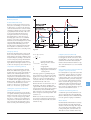
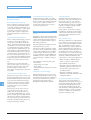
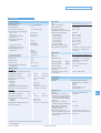
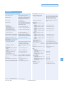
Restart inhibit for motors (ANSI 66)
Thermal overload protection (ANSI 49)
Setting ranges
Setting ranges
Motor starting current relative
to rated motor current
IMOTOR START/IMotor Nom
Rated motor current IMotor Nom
Max. permissible starting time
TStart Max.
Equilibrium time TEqual
Minimum inhibit time
TMIN. INHIBIT TIME
Max. permissible number of
warm startups nWARM
Difference between cold and
warm startups nCOLD – nWARM
Extension of time constant at
stop kτ at STOP
Extension of time constant at
running kτ at RUNNING
1.1 to 10 (in steps of 0.1)
1 to 6 A1) (in steps of 0.01 A)
1 to 320 s (in steps of 1 s)
0 min to 320 min (in steps of 0.1 min)
0.2 min to 120 min (in steps of 0.1 min)
Factor k
0.1 to 4 (in steps of 0.01)
Time constant
1 to 999.9 min (in steps of 0.1 min)
Thermal alarm ΘAlarm /ΘTrip
50 to 100 % of the trip excessive
temperature (in steps of 1 %)
Current warning stage IAlarm
0.5 to 20 A (in steps of 0.01 A)
Extension factor when stopped
kτ factor
1 to 10 with reference to the time
constant with the machine running
(in steps of 0.1)
1 to 4 (in steps of 1)
Rated overtemperature (for Inom)
1 to 2 (in steps of 1)
Tripping characteristic
For (I/k · Inom) ≤ 8
0.2 to 100 (in steps of 0.1)
40 to 200 °C (in steps of 1 °C)
Restart threshold
Where:
ΘRESTART
kR
ISTARTUP
IMOT Nom
TSTART max
τR
ncold
⎞
⎟
⎟
⎠
= Temperature limit
below which restarting
is possible
= k-factor for the rotor
= Startup current
= Motor rated current
= Max. startup time
= Thermal rotor time
constant
= Max. number of cold
starts
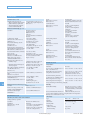
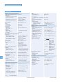
Undercurrent monitoring (ANSI 37)
Signal from the operational
measured values
Predefined with programmable logic
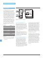
Temperature detection
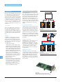
Temperature detection through internal module (only 7SK805/7SK806)
Number of temperature detectors 5
Measuring method
Pt 100 Ω or Ni 100 Ω or Ni 120 Ω
3-wire connection, shielded cable
Installation identification
“Oil” or “Ambient” or “Stator” or
“Bearing” or “Other”
Temperature detection through external RTD boxes
Connectable RTD-boxes
1 or 2
Number of temperature detectors Max. 6
per RTD-box
Pt 100 Ω or Ni 100 Ω or Ni 120 Ω
Selectable 2- or 3-phase connection,
shielded cable
Mounting identification
“Oil” or “Ambient” or “Stator” or
“Bearing” or “Other”
Thresholds for indications
For each measuring detector
Stage 1
Stage 2
Siemens SIP · 2008
Dropout ratios
Θ/ΘTrip
Θ/ΘAlarm
I/IAlarm
Tolerances
With reference to k · Inom
With reference to tripping time
Drops out with ΘAlarm
Approx. 0.99
Approx. 0.97
3 % or 75 mA1)
2 % class acc. to IEC 60255-8
3 % or 1 s for I/(k · Inom) > 1.25
3 % class acc. to IEC 60255-8
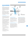
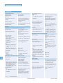
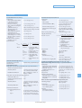
(Sensitive) ground-fault protection (ANSI 64, 50Ns, 51Ns, 67Ns)
Displacement voltage element for all types of ground fault (ANSI 64)
Setting ranges
Displacement voltage (measured)
Displacement voltage (calculated)
Delay time TDelay pickup
Additional trip delay TV Delay
V0> 1.8 to 200 V (in steps of 0.1 V)
3V0> 10 to 225 V (in steps of 0.1 V)
0.04 to 320 s or ∞ (in steps of 0.01 s)
0.1 to 40,000 s or ∞ (in steps of 0.01 s)
Operating time
Approx. 50 ms
Dropout ratio
0.95 or (pickup value –0.6 V)
Tolerances (measurement)
Pickup threshold V0 (measured) 3 % of setting value or 0.3 V
Pickup threshold 3V0 (calculated) 3 % of setting value or 3 V
Delay times
1 % of setting value or 10 ms
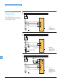
Phase detection for ground fault in an ungrounded system
Measuring method
–50 °C to 250 °C (in steps of 1 °C)
–58 °F to 482 °F or ∞ (no indication)
2
t = Tripping time in minutes
τth = Temperature-rise time
constant
I = Actual load current
Ipre = Preload current
k = Setting factor acc. to
IEC 60255-8
Inom = Rated (nominal) current of
the protected object
0.2 to 100 (in steps of 0.1)
2
( n cold − 1 ) ⋅ TSTART max
⎛ I STARTUP ⎞ ⎛
τR
ΘRESTART = ⎜
⎟ ⋅ ⎜⎜ 1– e
⎝ I Motor Nom ⋅ k R ⎠ ⎝
(I / k ⋅ I nom ) − (I pre / k ⋅ I nom )
2
(I / k ⋅ I nom ) − 1
2
t = τ th ⋅ ln
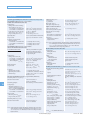
Measuring principle
Setting ranges
Vph min (ground-fault phase)
Vph max (healthy phases)
Tolerance
Measurement tolerance
acc. to VDE 0435, Part 303
–50 °C to 250 °C (in steps of 1 °C)
–58 °F to 482 °F or ∞ (no indication)
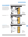
Technical Data page 7
Voltage measurement
(phase-to-ground)
10 to 100 V (in steps of 1 V)
10 to 100 V (in steps of 1 V)
3 % of setting value or 1 V
12