1
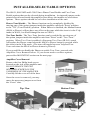
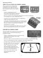
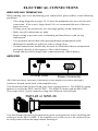
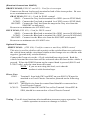
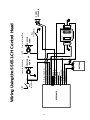
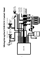
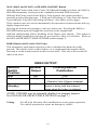
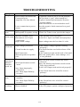
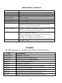
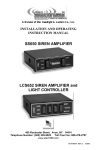
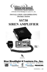
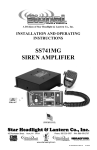
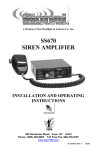
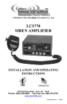
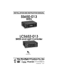
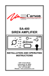
A Division of Star Headlight & Lantern Co., Inc.
INSTALLATION AND OPERATING
INSTRUCTION MANUAL
SS651 & SS651MT SIREN AMPLIFIER
LCS653 SIREN AMPLIFIER AND
LIGHT CONTROLLER
455 Rochester Street Avon, NY 14414
Phone: (585) 226-9025 Toll Free Fax: 888-478-2797
www.star1889.com
PLITSTR248 REV D 1/26/05
This page intentionally left blank.
INSTALLATION INFORMATION
MODELS:
SS651-008
SS651MT-008
LCS653
SERIAL NO: _________________________
PURCHASE DATE: ___________________
OPTIONS
DEALER: ___________________________
_____ Phaser Disabled
INSTALLATION DATE: ________________
_____ Two-Tone Enabled
INSTALLER: ________________________
Model and serial number located on the top of the amplifier unit
TABLE OF CONTENTS
GENERAL DESCRIPTION
INSTALLATION
2
3-11
GENERAL INSTALLATION
3
INSTALLER-SELECTABLE OPTIONS
3
MOUNTING........................................................................................ 4-5
Amplifier ......................................................................................4
Control Heads .............................................................................5
ELECTRICAL CONNECTIONS ...............................................6-11
SS651 Wiring Diagram.............................................................9
SS651MT Wiring Diagram....................................................10
LCS653 Wiring Diagram.......................................................11
OPERATION
12-13
Selector Switch..............................................................................12
Manual/Phaser..............................................................................13
Horn .................................................................................................13
Siren Output Chart.....................................................................13
SERVICE
14-16
TROUBLESHOOTING.....................................................................14
SPECIFICATIONS .............................................................................15
PARTS ....................................................................................................15
LIMITED WARRANTY ...................................................................16
RETURNS ..............................................................................................16
Installation Notes..................................................................................17
NOTICE
Due to continuous product improvements, we must reserve the right to change any specifications and
information contained in this manual at any time without notice. Signal Vehicle Products, Inc. makes
no warranty of any kind with regard to this manual, including, but not limited to, the implied
warranties of merchantability and fit ness for a particular purpose. Signal Vehicle Products, Inc. shall
not be liable for errors contained herein or for incidental or consequential damages in connection with
the furnishing, performance, or use of this manual.
-1-
Important:
Improper installation and/or use of these products may result in
vehicular collision, personal injury and/or death. Star Headlight & Lantern Co.,
Inc., and its subsidiaries shall not be held responsible for damages directly or
indirectly caused by improper installation or use of this product.
GENERAL DESCRIPTION
The SS651, SS651MT, and LCS653 Sirens are designed for single 100W speaker use. They
come standard with the amplifier unit as well as a remote control head (switch panel). The
primary operating modes are Wail, Yelp, Standby, Manual, and Horn. Both the Manual
Control and the Horn function will override all other functions, and can be utilized at any
time via a rocker switch. The Phaser function can be optionally disabled entirely with a
program jumper.
The SS651, SS651MT, and LCS653 units are designed to allow maximum versatility in
mounting. The control head is remote from the siren amplifier box creating a compact user
interface panel that can be easily mounted under the dashboard. The amplifier box can then
be mounted remotely in the trunk, under the dashboard, under the seat, or wherever
convenient. The SS651MT offers a waterproof switch assembly for motorcycle and marine
applications.
The siren amplifier has been designed with several protection features to provide exceptional
field service. Excessively high voltage detection will disable the siren output to protect both
the amplifier and the speaker. Fused inputs provide safety against reverse polarity. Speaker
protection shuts down the output if the speaker output becomes electrically shorted.
CAUTION: These protection features will not guard against overloading the outputs.
GENERAL INSTALLATION
Proper installation of the unit is essential for years of safe, reliable operation.
Please read all instructions before installing the unit. Failure to follow these
instructions can cause serious damage to the unit or vehicle and may void
warranties.
Qualifications - The installer must have a firm knowledge of basic electricity,
vehicle electrical systems and emergency equipment.
Keep These Instructions -
Unpacking -
Keep these instructions in the vehicle or other safe
place for future reference. Advise the vehicle operator
of the location.
Inspect contents for shipping damage. If any damage is found,
alert the carrier immediately. SS651and LCS653 contents should
include: an amplifier box with wiring pigtail, a control head
(switch panel), (6) six 1/4" quick connect terminals, and these
instructions. (Remote Panel with switches and terminals is not
supplied with SS651-AMP version). SS651MT contents should
include: an amplifier box with wiring pigtail, a weatherproof
control head (switch panel), and these instructions. Please contact
your supplier immediately if any components are missing.
-2-
INSTALLER-SELECTABLE OPTIONS
The SS651, SS651MT and LCS653 have Phaser Tone Disable and Two-Tone
Enable options that can be selected during installation. An internal jumper on the
printed circuit board inside the amplifier case allows the installer to select these
options. These options should be set before installation of the unit.
Phaser Tone Disable – The Phaser function can be completely disabled by
moving one of the option jumpers inside the amplifier unit from "Extra" position
to the "TD" (Tone Disable) position. When Phaser is disabled, the Manual button
(MAN or Phaser) will not have any effect on the tone while the siren is in the Yelp
mode (in WAIL, it will still change the tone to YELP).
Two-Tone Enable - The Two-Tone function can be enabled by moving one of
the option jumpers inside the amplifier unit from "Extra" to the "Two-Tone"
position. When Two-Tone is enabled, a European Two-Tone (HI-LO) sound
will replace the Phaser sound when the MAN or Phaser button is pressed while
the siren is in the Yelp mode. (The tone will toggle between Yelp and TwoTone each time the MAN or Phaser button is pressed).
If you would like to disable the Phaser or enable Two-Tone, proceed with
Amplifier Cover Removal below. If you do not need to set these options,
proceed the MOUNTING section on the next page.
Amplifier Cover Removal
Remove the four Philip head screws
located on the side of the amplifier unit.
DO NOT REMOVE THE TWO
RECESSED SCREWS ON THE
UNDERSIDE OF THE AMPLIFIER.
Carefully lift the cover off of the base.
Once the cover is removed, you may
move the necessary jumpers over from
the “Extra” slots.
Top View
Bottom View
-3-
MOUNTING
SAFETY PRECAUTIONS
For the safety of the installer, vehicle operator, passengers and the community
please observe the following safety precautions. Failure to follow all safety
precautions and instructions may result in property damage, injury or
death.
DO NOT mount in air bag deployment area.
Devices should be mounted only in locations listed in
SAE standard J1849.
Controls should be placed within convenient reach of
the driver.
Assure clearances before drilling in vehicle.
Sound levels produced by attached speakers can
cause permanent hearing loss.
Never operate this unit without adequate hearing
protection for you and others in the area.
(OSHA 1910.95)
AMPLIFIER
The SS651-AMP (used in the SS651, SS651MT and the LCS653) should be
mounted in a location such as the firewall, under the seat, in the trunk, or in the
saddlebag. It is not recommended to mount the amplifier in the engine
compartment or in an area that would be allowed direct exposure to weather
elements. Choose a mounting location away from any air bag deployment areas.
Assure adequate ventilation to prevent overheating.
The amplifier unit is provided with four mounting flanges with 1/4" holes. Using
the amplifier unit itself as a template, mark the location of the four mounting holes
to be drilled. Be sure to check for obstructions behind the mounting hole locations.
Drill the four mounting holes and secure the amplifier using appropriate hardware
(not supplied).
MOTORCYCLE/MARINE INSTALLATIONS (SS651MT ONLY!)
This SS651-AMP can be used on a motorcycle or for marine applications by
sealing the case with silicone sealant along the mating edges and around the
wire connector. In order to reduce water entry, the amplifier should be oriented
with the wire connector faced down. Only the waterproof switch assembly
found in the SS651MT (SS651MT-CH) should be used for wet location
operation.
-4-
(Mounting CONT’D)
SS651-CH and LCS653-CH CONTROL HEADS
The control head is designed for
mounting in an easily accessible
location such as under the dash, in
the overhead console, or in a center
console.
- Choose a mounting location
convenient to the operator and away
from any air bag deployment areas.
SS651-CH
LCS653-CH
- Be sure to choose a location that has at least two inches of depth to
accommodate the control head and cables.
- Consider wire routing and access to connections
when selecting location as well.
- Using the switch panel unit itself as a template, mark
the location of the two mounting holes to be drilled.
Be sure to check for obstructions behind the
mounting hole locations.
- Drill the two mounting holes and secure the switch
panel using appropriate hardware (not supplied).
SS651MT-CH CONTROL HEAD
The SS651MT-CH weatherproof control head is
designed for use in locations that may be
exposed to water.
- Choose a mounting location convenient to the
operator and away from any air bag
deployment areas.
SS651MT-CH
- Be sure to choose a location that has at least two inches of space on the right
side to accommodate the cable exiting the side of the control head.
- Consider wire routing when selecting location as well.
- The SS651MT-CH can be mounted
through the two holes in the rear
cover. To gain access to the
mounting holes, detach the rear
cover by removing the four screws
affixing it to the control head.
Remove these four screws
Mounting Holes
- Secure the switch panel using
appropriate hardware (not
supplied).
Rear of SS651MT-CH
-5-
ELECTRICAL CONNECTIONS
WIRE SIZE AND TERMINATION
When running your wires and making your connections, please adhere to the following
guidelines:
- The wiring diagrams on pages 12-13 show the minimum wire size used for each
connection. If the wire is longer than 10 ft. we recommend the use of the next
larger wire size.
- If using your own connectors, use only high quality crimp connectors.
- Make sure all connections are tight.
- Route wiring to prevent wear, overheating and interference with air bag
deployment.
- Use grommets and sealant when passing through compartment walls.
- Minimize the number of splices to reduce voltage drop.
- Ground connections should only be made to substantial chassis components,
preferably directly to the negative of the vehicle battery.
- Install and check all wiring before connection to the vehicle battery.
AMPLIFIER
-- 15 --
15 Amp Fuse
10 7
11 8
4
5
1
2
12 9
6
3
Power Connector
All of the necessary electrical connections to the amplifier are made through a
connector located on the back of the amplifier case.
You should also find enclosed with your siren a wiring harness. The SWH-28 wiring
harness is used in the SS651 and LCS653. The SWH-36 comes with the SS651MT.
They come with a 12-port connector using nine different colored leads.
SWH-28 or SWH-36
1 2 3
4 5 6
7 8 9
10 11 1 2
You should make all electrical connections to the wiring harness before installing the
connector on the SS651-AMP. If the amplifier ever needs service, the connector can
be easily removed from the amp without unwiring it.
-6-
(Electrical Connections CONT’D)
CONTROL HEADS
SS651-CH and LCS653-CH
Electrical power connections to the SS651-CH and LCS653-CH control heads are
made using the 1/4" quick connect terminals provided. After your wires are run, the
terminals can be crimped on to the ends, then plugged into the appropriate terminals
on the back of those control heads.
SS651MT-CH
The SS651MT-CH control head comes with 8’ leads. They will be connected to the
appropriate wires from the SWH-36 or lights by soldering or using appropriate
connectors (user supplied) and/or additional wire when necessary.
CONNECTION OF WIRES FROM THE AMP
The wiring diagrams on pages 9-11 show the specific details of how to connect the
wiring harness from the amplifier, and the different control heads, to each other and
to the vehicle.
RED LEAD (PIN #1) – Used for Power
Connect the red wire from the amplifier to +12 VDC. It is strongly
recommended that you connect to a 12 VDC source that is present only when
the vehicle ignition is in the on position. A power relay may also be used. Be
sure to use a minimum size #16 AWG wire. The power supply of the unit must
be capable of delivering peak currents up to 50 amps for adequate short circuit
protection and reliable operation. The unit is internally fused.
BLACK LEAD (PIN #2) - Ground
Connect the black wire from the amplifier to the negative side of the battery or
to a good chassis ground. Be sure to use minimum size #16 AWG.
ORANGE LEAD (PIN #3) - Used for HORN control
SS651: Connect the Orange lead to terminal 1a (MAN) of SW2
LCS653: Connect the Orange lead to terminal 1a of SW4.
For the SS651, SS651MT and LCS653 on vehicles with ground-side (negative)
switched horns, also connect the Orange wire to the wire between the horn
switch on the vehicle and the horn itself (see wiring diagrams). Be sure to use a
minimum size #18 AWG. The HORN button on your control head and the
horn switch on your vehicle will act identically. Either one will activate both
the vehicle horn and the siren horn at the same time. For the SS651MT, there
is no HORN button on the control head. On motorcycles with ground-side
switched horns, pressing the horn button on the motorcycle will activate both
the motorcycle horn and the siren horn.
YELLOW LEAD (PIN #6) - Used for MANUAL control
SS651: Connect the Yellow lead to terminal 1b (HORN) of SW2
LCS653: Connect the Yellow lead to terminal 1b of SW4.
SS651MT: Connect the Yellow lead from the amp to the Yellow lead from
the control head.
Be sure to use a minimum size #18 AWG wire.
-7-
(Electrical Connecti ons CONT’D)
BROWN LEADS (PINS #7 and #12) - Used for siren output
Connect one Brown lead to each terminal or lead of the siren speaker. Be sure
to use a minimum size #16 AWG wire.
GRAY LEAD (PIN #9 ) - Used for WAIL control
SS651: Connect the Gray lead to terminal 1a of SW1 (next to YELP label)
LCS653: Connect the Gray lead to terminal 1a of SW3 (next to YELP label)
SS651MT: Connect the Gray lead from the amp to the Gray wire from the
SS651MT switch panel.
Be sure to use minimum size #18 AWG wire.
BLUE LEAD (PIN #11) - Used for YELP control
SS651: Connect the Blue lead to terminal 1b of SW1 (next to WAIL label)
LCS653: Connect the Blue lead to terminal 1b of SW3 (next to WAIL label)
SS651MT: Connect it to the Blue wire from the SS651MT switch panel.
Be sure to use minimum size #18 AWG wire.
Optional Connections:
GREEN LEAD: (PIN #10)- Used for remote or auxiliary HORN control
This wire is used in vehicles with a positive-side switched horn to synchronize
the vehicle horn and the siren horn (similar to the Orange wire on vehicles with
negative [ground-side] switched horns).
Connect the Green wire to the +12vdc switched horn ring circuit. Both the
vehicle horn and the siren horn will be activated when the horn in the vehicle is
pressed. When the HORN button on the control head is pressed (SS651 and
LCS653 only), only the siren horn will sound.
NOTE: If you are not using this lead, cut it short &
insulate it with electrical tape.
Please Note:
SS651 : Terminal 1 from both SW1 and SW2 on your SS651-CH must be
attached to a Good Chassis Ground as pictured on the following
page.
SS651MT: The Black wire from the control head should be connected to a
Good Chassis Ground.
LCS653: Terminal 3 from SW1 & SW2 as well as Terminal 1 from SW3 &
SW4, should be connected to a Good Chassis Ground.
Testing - Test all siren functions after installation to assure proper operation. Test
vehicle operation to assure no damage to vehicle.
-8-
-9-
SS651-AMP
-
BATTERY
+
VEHICLE
OR
HORN
Positive Switching Horn
12 - Brown (#16 AWG)
11 - Blue (#18 AWG)
10 - Green (#18 AWG)
9 - Gray (#18 AWG)
8 - No Connection
7 - Brown (#16 AWG)
6 - Yellow (#18 AWG)
5 - No Connection
4 - No Connection
3 - Orange (#18 AWG)
2 - Black (#16 AWG)
1 - Red (#16 AWG)
Horn
Switch/Relay
+12V
+12V
SW2
1a
MAN
1a
YELP
1
1
SW1
1b
1b
HORN
Horn
Switch/Relay
WAIL
VEHICLE
HORN
Negative Switching Horn
Wiring Using the SS651-CH Control Head
+
11 OHM
SPEAKER
SS651-AMP
+
BATTERY
-
VEHICLE
OR
HORN
Positive Switching Horn
12 - Brown (#16 AWG)
11 - Blue (#18 AWG)
10 - Green (#18 AWG)
9 - Gray (#18 AWG)
8 - No Connection
7 - Brown (#16 AWG)
6 - Yellow (#18 AWG)
5 - No Connection
4 - No Connection
3 - Orange (#18 AWG)
2 - Black (#16 AWG)
1 - Red (#16 AWG)
Horn
Switch/Relay
+12V
+12V
PHASER
LIGHTS
FRONT
BEACON
Black (#18AWG)
Red (#12 AWG)
Yellow (#18 AWG)
Gray (#18 AWG)
LCS653-CH (Front View)
YELP
WAIL
Horn
Switch/Relay
Blue (#18 AWG)
VEHICLE
HORN
Negative Switching Horn
+
Power To
Beacon
Power To
Front Lights
11 OHM
SPEAKER
Wiring Using the SS651MT-CH Control Head
Red (#18 AWG)
Red (#18 AWG)
-10-
-11-
SS651-AMP
+
BATTERY
-
20 AMP
MAX
FUSE
+12V
User
Supplied
Fuses
20 AMP
MAX
FUSE
VEHICLE
OR
HORN
Positive Switching Horn
12 - Brown (#16 AWG)
11 - Blue (#18 AWG)
10 - Green (#18 AWG)
9 - Gray (#18 AWG)
8 - No Connection
7 - Brown (#16 AWG)
6 - Yellow (#18 AWG)
5 - No Connection
4 - No Connection
3 - Orange (#18 AWG)
2 - Black (#16 AWG)
1 - Red (#16 AWG)
Horn
Switch/Relay
+12V
SW2
SW1
OFF
1
2
3
ON
OFF
SW2
SW1
ON
OFF
ON
SW3
YELP
SW4
MAN
WAIL HORN
LCS653-CH (Front View)
SW3
SW4
OFF
1
1a
YELP
1a
MAN
2
1
1
3
ON
1b
WAIL
Horn
Switch/Relay
1b
HORN
VEHICLE
HORN
Negative Switching Horn
REAR VIEW OF
LCS653-CH
Power To Lights
Controlled by SW2
Power To Lights
Controlled by SW1
+
11 OHM
SPEAKER
Wiring Using the LCS653-CH Control Head
OPERATION
These units are designed for easy operation under the stress associated with highspeed pursuit. Most siren functions are accessible with one simple motion without
repetitive activation of switches or automatic timed switching that can interfere with
desired operation.
SELECTOR SWITCHES
There are three different control heads (switch panels) that work in conjunction with
the SS651-AMP siren amplifier. The SS651-CH is used for the SS651 Siren. The
SS651MT-CH is used for the SS651MT Siren. The LCS653-CH is used in the
LCS653 Siren.
All three switch panels will contain a three-position switch labeled WAIL/YELP.
This switch will control the primary operating function of the siren.
Wail - A normal rise-fall tone used on highways and areas with low traffic
or constant traffic flow.
Center Off – (Manual/Standby) –
A silent/standby mode that allows momentary push-button Manual
(MAN) or Phaser and momentary push-button Horn. The siren
output winds down when the Manual momentary switch is released.
Yelp - A rapid warble tone used in light to moderately congested areas.
SS651MT-CH
SS651-CH
LCS653-CH
-12-
MAN (SS651 and LCS653) or PHASER (SS651MT) Button
With the Wail/Yelp switch in the Center Off (Manual/Standby) position, the MAN or
PHASER momentary switch provides a manually activated Wail siren tone.
With the Wail/Yelp switch in the Wail or Yelp position, this switch provides a
generally quicker changing tone. A Wail tone will change to Yelp when this button
is pressed and a Yelp tone will change to Phaser. (See tables on next page).
These quicker tones are used to momentarily alert motorists at intersections and very
highly congested areas.
Pressing the button once changes t o the next faster tone. Pressing the MAN or
PHASER button again will toggle the siren back to the original tone.
Optional configuration allows disabling of the Phaser tone entirely. This option is
selected during installation and may be governed by State or Local laws. (Refer to
the INSTALLER SELECTABLE OPTIONS section on page 3).
HORN Button (SS651 and LCS653 only)
This momentary push-button switch provides a simulated air-horn tone while
pressed. This can be used to either replace, or to supplement the normal vehicle
horn and is useful at intersections or in low noise areas. This tone will override all
other siren tones.
Selector
Switch
Position:
Wail
Yelp
Manual
(Standby)
SIREN OUTPUT:
Speaker
Pressing Manual
Output
Pushbutton
Wail
Yelp
No Output
Yelp
Phaser
(Remains Yelp if Phaser disabled)
Creates a manual WAIL tone while
button is being held that sweeps
down when the button is released.
(NOTE: PHASER may be optionally disabled via program jumpers.
See INSTALLER-SELECTABLE OPTIONS on page 3.)
Testing -
Test all siren functions after installation to assure proper operation.
Test vehicle operation to assure no damage to vehicle.
-13-
TROUBLESHOOTING
Symptom
No power
Possible Cause
Power source not turned on
Connector loose
Amplifier 15A fuse blown
Loose connection at power
source
No siren
tone
Distorted
siren sound
Speaker assembly loose
Intermittent Aux. Input
connection
High vehicle voltage
Circuit breaker in supply
Bad Connection
Shorted speaker or speaker
wire
Horn switch stuck
MAN push-button switch
stuck
Aux. Input improperly
connected
Aux. Horn Input Polarity
reversed
Wrong siren Two-Tone option jumper
tone
installed
Aux. Horn Input Polarity
reversed
Phaser not
working
Is ignition switch in AUX or ON position?
Do you hear a “pop” when turned on?
Is power hooked up backwards? Positive
ground vehicle?
Is an external fuse or circuit breaker used?
Are the negative leads connected to a good
ground?
High voltage protection
Input voltage must be less than 16 volts.
Bad speaker or speaker wiring Check for a short or an open in the output.
Intermittent High voltage protection
siren tone
Horn
function or
Manual
function
stuck on
Check
Phaser disabled
Is the speaker bell or tip loose?
Is the Aux. Input used and wired properly?
Input voltage must be less than 16 volts.
Is the vehicle voltage regulator working
properly?
Is a circuit breaker used with at least a 50A
rating?
Is the connector tight on the back of the unit?
Does the speaker have water damage, or is
a wire pinched?
Does the horn switch return fully when
released?
Does the MAN push-button switch return
fully when released?
Is the AUX Input used and wired properly?
Is the Green horn wire wired for correct
polarity?
Is the TT jumper option properly configured?
Is the Green horn wire wired for correct
polarity?
Is the TD jumper option configured properly?
-14-
SPECIFICATIONS
Input Voltage
Input Current
Standby Current
Output Power
Siren Frequency
High Voltage Protection
Short Circuit Current
Operating Temperature
Controls
Connections
(12-Pin Connector)
Size
Boxed Weight
10 - 16 VDC (negative ground)
8 Amps @ 13.6 VDC (100W speaker)
Less than 20 mA
105 WATTS RMS MAX. (15.0 VDC - single 100W speaker)
675Hz - 1633Hz
16 - 18 VDC will cause siren output to cease, resume at normal
50 AMPS (supply circuit must be capable of supplying this)
-15° F to +140°F
3-position primary mode rocker switch (Wail, Yelp, and Standby)
Momentary 3-position rocker switch (Horn and Manual)
Phaser disable (jumper programmable)
Detachable, 12-pin, positive locking connector with pigtail leads for
Amplifier. (1) Positive, (1) Negative, (2) Speaker, Wail, Yelp, Horn,
Manual, and auxiliary positive switching Horn.
Amplifier: 2” High, 6” Wide, 5¼” Deep
(plus 3/4" flange on each side)
SS651-CH and LCS653-CH- Control Head (Switch Panel):
3" High x 2-1/4" Wide, x 1-1/2" Deep
SS651MT-CH - Weatherproof Control Head:
2.5" High x 4.5" Wide x 2-1/8" Deep (3" Deep with switches)
SS651and LCS653 - 3.5 lbs.
SS651MT - 4.4 lbs.
PARTS
The following parts are available from Signal Vehicle Products:
Part
Description
P30235-18P
Amplifier Top Cover
P30234-18P
Amplifier Bottom Mounting Plate
SWH-28
SS651 and LCS653 Wiring Harness
SWH-36
SS651MT Wiring Harness
30050-28
Amplifier Case Screws
30028-6
15 Amp Automotive Blade Fuse for Amplifier
30032-8
TIP36C Power Transistor
30007-41
3-Position Rocker Selector Switch (WAIL/YELP)
30007-42
Momentary Rocker Switch (HORN/MAN)
SW-40
Lighted ON/OFF Rocker Switch (LCS653-CH)
-15-
LIMITED WARRANTY
Signal Vehicle Products warrants this new product to be free from
defects in material and workmanship, under normal use and service,
for a period of one (1) year from the date of delivery to the first userpurchaser.
During this warranty period the obligation of Signal Vehicle
Products is limited to repairing or replacing, as Signal Vehicle
Products may elect, any part or parts of such product which after
examination by Signal Vehicle Products is determined to be defective
in material and/or workmanship.
This warranty does not cover labor charges for removal or reinstallation of the product. Fuses and lamps are not covered under
this warranty.
This warranty does not extend to any unit that has been subjected to
abuse, misuse, improper installation or which has not been
adequately maintained, nor to units which have problems related to
service or modification at any facility other than the manufacturer.
THERE ARE NO OTHER WARRANTIES, EXPRESSED OR
IMPLIED, INCLUDING BUT NOT LIMITED TO, ANY IMPLIED
WARRANTIES OF MERCHANTABILITY OR FITNESS FOR A
PARTICULAR PURPOSE. IN NO EVENT SHALL SIGNAL
VEHICLE PRODUCTS BE LIABLE FOR ANY LOSS OF PROFITS
OR ANY INDIRECT OR CONSEQUENTIAL DAMAGES ARISING
OUT OF ANY SUCH DEFECT IN MATERIALS OR
WORKMANSHIP.
If you have any questions concerning this or any other SVP product,
please contact our Customer Service Department at (585) 226-9025.
RETURN
If a product must be returned for any reason, please call 585-226-9025 and ask for
the Repair Department. At that time the necessary paperwork can be filled out and
you can obtain a Returned Goods Authorization number (RGA#) before you ship
the product to SVP. Please write the RGA# clearly on the package near the mailing
label.
-16-
Installation Notes
__________________
__________________
__________________
__________________
__________________
__________________
__________________
__________________
__________________
-17-
A Division of Star Headlight & Lantern Co., Inc.
www.star1889.com
-18-