1
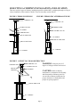
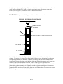
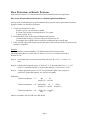
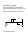
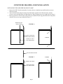
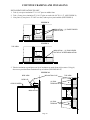
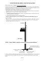
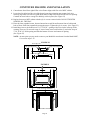
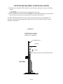
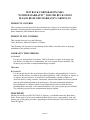
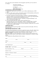
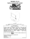
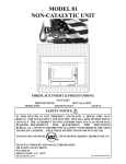
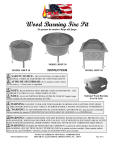
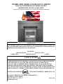
MODEL 80ZC ZERO CLEARANCE CABINET
FOR USE WITH FIREPLACE MODEL 80 ONLY
RESIDENTIAL INSTALLATION ONLY
Contact your insurance company for coverage and installation inspection.
WARNING
Do not attempt to build a fire in this product. It has been designed and safety tested for use
only with Model 80 manufactured by NEW BUCK CORPORATION. Read and follow the
installation and operating instructions for this model.
FEATURES
PREPARATIONS
INSTALLATION
OPERATION
MAINTENANCE
SAFETY
SAFETY NOTICE
IF THIS HEATER IS NOT PROPERLY INSTALLED, A HOUSE FIRE MAY RESULT.
FOR YOUR SAFETY, FOLLOW THE INSTALLATION INSTRUCTIONS.
CONTACT THE AUTHORITY HAVE JURISDICTION ( SUCH AS MUNICIPAL
BUILDING DEPARTMENT, FIRE DEPARTMENT, FIRE PREVENTION BUREAU,
ETC.) SHOULD BE CONSULTED BEFORE INSTALLATION TO DETERMINE THE
NEED TO OBTAIN A PERMIT. KEEP THESE INSTRUCTIONS FOR FUTURE USE.
TESTED AND LISTED BY:
ITS/WARNOCK HERSEY, MIDDLETON, WI
MANUFACTURED BY NEW BUCK CORPORATION
200 ETHAN ALLEN DRIVE,
SPRUCE PINE, N.C. 28777
www.buckstove.com
January 2013
TABLE OF CONTENTS
Cabinet Identification.................................................................................................................... 3
Caution and Warnings................................................................................................................... 4
Installation Precautions ................................................................................................................. 5
Selecting Chimney Installation and Location ............................................................................ 6-7
Alternate Floor Protector .............................................................................................................. 8
Framing Construction and Installation:
Choosing 80ZC Cabinet Installation location ............................................................................... 9
Installing Top and Side Panels .................................................................................................... 10
Installing Insulation .................................................................................................................... 11
Installing 80ZV Cabinet, Flat On Floor Installation ................................................................... 12
Floor Protector or Finished Hearth Flat On Floor Installation ................................................... 13
Installing 80ZV Cabinet, Optional raised Base Installation ....................................................... 14
Floor Protector or Finished Hearth Optional raised Base Installation ........................................ 15
Installing Chimney ...................................................................................................................... 16
Electrical Installation .................................................................................................................. 17
Framing Construction Installation .............................................................................................. 18
Framing Construction Exterior or Chase .................................................................................... 19
Framing Construction Corner Location ..................................................................................... 20
Installing Model 80 into 80ZC Cabinet ................................................................................. 21-23
Cleaning Unit / Safety Precaution .............................................................................................. 24
Preventive Maintenance / Chimney Cleaning............................................................................. 25
Warranty ..................................................................................................................................... 26
MODEL 80 ROOM HEATER AND MODEL 80ZC
CABINET IDENTIFICATION
The following manual is for the 80ZC cabinet ONLY. If you require information on the Model 80
unit that fits inside this cabinet, consult your Model 80 wood stove installation manual or please
download the Model 80 wood stove manual from the “Product Manuals” section of our website.
Thank you for choosing Buck Stove!
(31)
(1)
(30)
(29)
(32)
(33)
(28)
(2)
(3)
(4)
(27)
(5)
(6)
(7)
(8)
(26)
(25)
(24)
(9)
(10)
(11)
(23)
Buck Stove
(22)
(12)
(13)
(14)
(21)
1.
2.
3.
4.
8" Flue Exit
Hot Air Vent
Catalyst Probe
By Pass Damper & Spring
Handle
5. Air Wash Screen
6. Lower Heat Shield
7. Door
8. Side Trim Panel (Left)
9. Door Handle & Spring Handle
10. Expanded Metal Screen
(Right Side)
(20) (19) (18)
(17) (16) (15)
11. Primary Air Control
(Right Side)
12. Automatic / Off / Man.Switch
13. Blower Control (Rheostat)
14. Power Cord
15. Right Access Cover Door
16. Hearth
17. Shot Gun Air Control
18. Left Access Cover Door
19. Front Bottom Frame
20. Bottom Trim Panel
21. Expanded Metal Screen
(Left Side)
Page 2
22. Primary Air Control
(Left Side)
23. Hinge Block
24. Hinge Pin Cap
25. Side Trim Panel (Right)
26. Side Outside Trim Panel (Left)
27. Trim Left Side (Black)
28. Louver
29. Front
30. Top Outside Trim Panel
31. Trim Top (Black)
32. Trim Right Side (Black)
33. Side Outside Trim Panel (Right)
RESIDENTIAL INSTALLATION
Listed NEW BUCK CORPORATION:
Model 80ZC Zero Clearance Cabinet Assembly for use with Model 80 only.
CAUTION: Read through all of these instructions carefully. Follow approved Chimney Manufacturer’s Installation exactly. Failure to install the Cabinet Fireplace, Stove and Chimney as described in
the instructions will void the manufacturer’s warranty and may have an effect on your Homeowner’s
Insurance. A major cause of chimney related fires is failure to maintain required clearances (air spaces)
to combustible materials. It is of the utmost importance that these parts be installed only in accordance
with these instructions.
DO NOT USE CHEMICALS OR FLUIDS TO START THE FIRE.
DO NOT BURN GARBAGE OR FLAMMABLE FLUIDS.
DO NOT BUILD A FIRE DIRECTLY INSIDE THE ZC CABINET. IT IS DESIGNED
SOLELY FOR HOUSING THE MODEL 80 STOVE.
WARNING: THIS FIREPLACE HAS NOT BEEN TESTED WITH AN UNVENTED
GAS LOG SET. TO REDUCE THE RISK OF FIRE OR INJURY DO NOT INSTALL
AN UNVENTED GAS LOG SET INTO THIS FIREPLACE.
CAUTION: Never use gasoline, gasoline-type lantern fuel , kerosene, charcoal lighter fluid
or similar liquids to start or “freshen up” a fire in this fireplace. Keep all such liquids well away
from the fireplace while it is in use.
Disposal of Ashes:
Ashes should be placed in a metal container with a tight fitting lid. The closed container of
ashes should be placed on a noncombustible floor or on the ground, well away from all combustible materials, pending final disposal. If the ashes are disposed of by burial in soil or otherwise
locally dispersed, they should be retained in the closed container until all cinders have thoroughly cooled.
Do Not Use Grate or Elevate Fire-Build Wood Fire Directly on Hearth in Stove.
For operation and use of air and damper controls, see stoves Owners Manual for use of air and
damper control.
For operation and use of electrical assemblies, see stoves Owners Manual for use of electrical
assemblies
USE SOLID WOOD FUEL ONLY.
The Zero-Clearance Cabinet and the Model 80 Installed (hereafter referred to as the 80ZC) is designed
for installation in a family dwelling, where minimum clearance is desired.
Page 3
INSTALLATION PRECAUTIONS
The following precautions are mandatory for a safe installation.
(A) Compliance with local building codes and regulations is mandatory.
(B) Be careful not to damage the unit in handling and unpacking component parts and accessories.
(C) Model 80ZC Cabinet, use only 8"listed 2100º UL 103 HT TYPE Chimney with the 80ZC
Cabinet (ONLY AFTER) New Buck Corparation Stove 80 has been installed into the 80ZC
Cabinet.
(D) The chimney must extend a minimum of three feet (3') above the highest point where it penetrates
the roof (three feet (3') above a flat roof or up to a 2 /12 pitch roof ) and the chimney must extend a
minimum of two feet (2') higher than any portion of the building within ten feet (10') of the chimney. The minimum height is fourteen and one half feet (14 1/2'). The maximum height is forty two
feet (42'). A two-inch (2") clearance must be maintained between the chimney and any combustible
materials at all points.
(E) A rain cap must be used to terminate the chimney to prevent down-draft. Use the factory approved
rain cap which is approved for the type chimney being installed.
(F) DO NOT CONNECT THIS UNIT TO A CHIMNEY FLUE SERVING ANOTHER
APPLIANCE. DO NOT USE A FLUE INTENDED FOR A GAS APPLIANCE.”DO
NOT CONNECT TO ANY DISTRIBUTION DUCT OR SYSTEM.
CAUTION
THE STRUCTURAL INTEGRITY OF THE HOME, FLOOR, WALL AND
CEILING/ROOF MUST BE MAINTAINED. (MOVE OPENING AND/OR
REPOSITION HEATER LOCATION IF NECESSARY)
Page 4
SELECTING A CHIMNEY INSTALLATION AND LOCATION
There are two basic types of chimney installation possible with the 80ZC; straight up through a ceiling or
a chase installation, either outside or inside. These are normally used as follows:
FIGURE 1 THROUGH CEILING
FIGURE 2 THROUGH CATHEDRAL CEILING
CHIMNEY CAP
CHIMNEY CAP
CHIMNEY PIPE
STORM COLLAR
FLASHING
STORM COLLAR
CHIMNEY PIPE
METAL FIRE STOP
FLASHING
METAL FIRE STOP
METAL FIRE STOP
Z.C. CABINET
Z.C. CABINET
FIGURE 3 OFFSET TO CLEAR OBSTRUCTION
WARNING: Only one pair of 15
CHIMNEY CAP
CHIMNEY PIPE
degree or 30 degree offsets can be used.
STORM COLLAR
ADJUSTABLE
CHIMNEY
FLASHING
CAUTION: Refer to chimney
manufacturer’s instructions for assembly
and disassembly of chimney parts. Be
sure to follow chimney instructions for
proper clearances to combustibles and
proper air spacing required.
ELBOWS
METAL FIRE STOP
Z.C. CABINET
Page 5
A. Straight up through ceiling (See Page 6 Figures 1 and 2). This is a simple installation normally used
when installing a Model 80ZC inside an existing room and in some cases, in new construction.
Refer to (Page 6 Figure 3) if an offset to clear an obstruction is needed.
WARNING: Only one pair of 15 degree or 30 degree offsets can be used.
FIGURE 4 EXTERIOR WALL CHASE
CHIMNEY CAP
STORM COLLAR
FLASHING
CHIMNEY PIPE
OPTIONAL METAL FIRESTOP RADIATION
SHIELD
WALL BAND
Z.C. CABINET
B. Exterior Chase Installation: (See Figure 4). A chase is an enclosure built specifically to house a
chimney. The interior of a chase is open from Model 80ZC to the roof, eliminating the need to cut
through ceilings and the roof. Normally, a chase is built through the wall and the Model 80ZC is
located in the bottom of the chase, with the front of the unit flush with the interior wall. Chases are
commonly veneered on the outside with brick, stone or wood to give the appearance of a
conventional fireplace flue. Occasionally, they are built inside and boxed in, similar to a stairwell.
When making a chase installation, it is important to read the chimney manufacturer’s instructions
prior to building, as there are specific requirements for bracing a free standing flue that must be
planned for. There are also occasions where offsets are used within a chase to accommodate unusual
building designs or to locate the Model 80ZC further into a room.
Page 6
Floor Protection: or Hearth Protector
Floor protection must be 3/8” minimum thickness non-combustible material or equivalent.
How to use alternate materials and how to calculate equivalent thickness.
An easy means of determining if a proposed alternate floor protector meets requirements listed in the
appliance manual is to follow this procedure:
1. Convert specification to R-value:
R-value is given—no conversion is needed.
K– factor is given with a required thickness (T) in inches:
C-factor is given: R=1/C
2. Determine the R-value of the proposed alternate floor protector.
Use the formula in step (1) to convert values not expressed as “R”
For multiple layers, add R-values of each layer to determine the overall R-value.
3. If the overall R-value of the system is grater than the R-value of the specified floor protector, the
alternate is acceptable.
Example:
The specified floor protector should be 3/4” thick material with a K-factor of 0.84.
The proposed alternate is 4” brick with a C-factor of 1.25 over 1/8” mineral board with a
K-factor of 0.29.
Step (a): Use formula above to convert specification to R-value. R= 1/K x T = 1/0.84 x .75 =
0.893
Step (b): Calculate R of proposed system. 4” brick of C=1.25, therefore Rbrick = 1/C = 1/1.25
=0.80 1/8” mineral board of K = 0.29, therefore Rmin.bd. =1/029 x0.125 = 0.431
Step (c): Compare proposed system R of 1.231 to specified R of 0.893. Since proposed
system R is greater than required , the system is acceptable.
Definitions:
Thermal conductance = C =
Btu =
W
(hr)(ft²)(°F) (m²)(°K)
Thermal conductance = K = (Btu)(inch) = W =
(Btu)
(hr)(ft²)(°f) (m)(°K) (hr)(tf)(°F)
Thermal conductance = R = (ft²)(hr)(°F) = (m²)(°K)
Btu
W
Install in accordance with 24 CFR, Part 3280 (HUD).
Page 7
FRAMING CONSTRUCTION AND INSTALLATION
CHOOSING 80ZC CABINET INSTALLATION LOCATION
Except as noted, the 80ZC can be installed almost anywhere you desire. There are, however, a few clearance
and framing restrictions that must be followed. See Figure 17, Figure 18, and Figure 19 to make sure that
these clearance restrictions are met. It is much wiser to place your Model 80ZC correctly at the start.
You must ensure that the floor is of adequate strength to accept the load of this unit. If inadequate, the floor
will require additional support, such as bracing. NOTE: A wooden base constructed of plywood or 2" x 4"
boards is required in order to get proper clearance above the extended hearth (millboard, rock stone, etc.).
Good planning is essential for a satisfactory installation, therefore, at this point you should have decided
where the 80ZC is to be located and the route the chimney will follow to the roof-straight up or chase. If
you cannot decide the best route, contact your dealer for assistance with the planning.
29
"
FIGURE 5
29"
C
LO ORN
C A ER
TI
ON
ADJACENT ROOM OF
EXTERIOR CHASE
29"
INTERIOR LOCATION
Above (Figure 5) are framing location examples with depth dimensions for some typical configurations.
These are finished measurements so install accordingly.
Page 8
CONTINUED FRAMING AND INSTALLATION
INSTALLING TOP AND SIDE PANELS TO 80ZC
1. Remove the 80ZC from box and pallet. Lay brass louvers, insulation cap and front side screens to
side for use later.
2. Take Left Side Panel and place front of Left Side Panel against back of left front side, with the
(2) two screws provided fasten Left Side Panel to Cabinet. Repeat process for right side.(See Figure 6)
3. Place top panel over and in front of side panels just installed. Fasten top panel ends to the side panels
with the (2) two screws provided (See Figure 7).
REAR OF LEFT
FRONT SIDE
FIGURE 6
BACK OF FRONT
LEFT SIDE PANEL
SCREWS
FRONT OF LEFT
OUT SIDE PANEL
TOP OUT SIDE PANEL
FIGURE 7
FRONT 80ZC BOX
FRONT OF LEFT
OUT SIDE PANEL
Page 9
SCREWS
CONTINUE FRAMING AND INSTALLING
INSTALLING INSULATION TO 80ZC
1. Take (1) one piece insulation 8" X 11 1/2" place in middle front.
2. Take (2) two pieces insulation 8" X 10 1/2" place on each side of 8" X 11 1/2". (SEE FIGURE 8)
3. Now place (2) two pieces 8" X 48" over the (3) three pieces just installed. (SEE FIGURE 9)
FIGURE 8
INSULATION - (3) THREE PIECES
SIDE BY SIDE
8" X 10"
8" X 11 1/2"
8" X 10"
FIGURE 9
TOP VIEW
INSULATION - (2) TWO PIECES
ON TOP OF OTHER INSULATION
8" X 48"
3. Take the insulation cap and place rear lip of insulation cap under front of pipe starter. Using (4)
four screws provided fasten insulation to top of cabinet. (SEE FIGURE 10)
FIGURE 10
SIDE VIEW
INSULATION CAP
REAR LIP
(2) TWO
SCREWS
PIPE STARTER
INSULATION
(2) TWO
SCREWS
Page 10
TOP VIEW
CONTINUED FRAMING AND INSTALLATION
INSTALLING 80ZC CABINET FLAT ON THE FLOOR
Framing must be accomplished after the Model 80ZC is set in place. The chimney can be installed after
framing, but installation is considerably more difficult and in some cases, impossible. Therefore, it is recommended that the chimney be installed prior to framing when a choice exists.
POSITIONING 80ZC CABINET FOR INSTALLATION AS FOLLOWS
Thoroughly clean the area where the unit and hearth extension will be placed. Remove any carpeting/
padding from the area where the 80ZC cabinet will be installed.
1. Layout the location on the floor for the ZC cabinet .The structural integrity of the home, floor, wall
and ceiling/roof must be maintained.
2. Now place the Model 80ZC cabinet in desired location.
NOTE: If a optional raised base is to be installed, see OPTIONAL RAISED BASE (Page 14).
SAFETY SHIELD
One (1) 6” X 47 1/2” sheet metal safety shield is supplied, place 4" under the cabinet and 2” forward
in front of unit, out under the floor protector or finished hearth. Attach 6” X 47 1/2” safety shield
using sheet metal screws. (See Figure 11).
FIGURE 11
SIDE VIEW
80ZC CABINET
NOTE: “Safety Shield for hearth extension must be used on installation.”
FLOOR PROTECTOR OR
FINISH HEART EXTENSION
1-A SAFETY SHIELD
6” X 47 1/2”
4”
4" BACK FROM
FRONT OF UNIT
2”
2" FORWARD FROM
FRONT OF UNIT
1-A Safety shield for millboard hearth extension for flat on the floor installation. Place (4") four inches of
safety shield under the ZC Cabinet. Place floor protector or finished hearth extension on top of safety
shield.
Page 11
CONTINUED FRAMING AND INSTALLATION
FLOOR PROTECTOR OR FINISHED HEARTH EXTENSION FLAT ON THE FLOOR
You must use a non-combustible material or a UL listed floor protector R-Value 0.6 .( SEE FLOOR
PROTECTION Page 8) All the way against front of cabinet and a minimum of 16" in front of stove feed
door opening and 47 1/2" the width of the cabinet (See Figure 12)
Construct the hearth extension (floor protector or finished hearth) out of non-combustible inorganic
building materials as follows:
a. The hearth extension must extend 16" from the stove feed door opening and against front of
80ZC cabinet. (See Figure 12).
b. The hearth extension width must be at least 47 1/2". (See Figure 12).
c. The hearth extension must be made of brick 2” thick or a listed “Floor Protector” or “Hearth
Extension” with R- value of: R=0.6 , or a hearth extension made of non-combustible inorganic
material with a K * factor of K=2.5 BTU ( (HR)(ft2)(F/in.) (See Page 8)
WARNING:
Install the floor protector or finished hearth extension only as specified. The hearth
extension must be a minimum of 16" in front of the stove feed door opening and must be 47 1/2" wide
minimum. NOTE: Be sure to place safety shield under 80ZC and hearth protector or finished
hearth.
NOTE: No floor protector or finished hearth extension is needed directly under the Model 80ZC Cabinet, only the safety shield .
FIGURE 12
16”
47 1/2”
FLOOR PROTECTOR OR FINISH HEARTH EXTENSION
Page 12
CONTINUED FRAMING AND INSTALLATION
INSTALLING 80ZC CABINET WITH OPTIONAL RAISED BASE
WOODEN RAISED BASE
A wooden raised base constructed of plywood or 2" x 4" boards is required in order to get proper
clearance above the extended hearth (millboard, rock stone, etc.).
The base for the Model 80ZC must be level with or slightly higher than the “finished” hearth height
dimension (A) See Figure 13.
SAFETY SHIELDS
a. One (1) 6” X 47 1/2” sheet metal safety shield is supplied. Place 4" of shield under the raised base
under cabinet and 2” forward in front of unit, under the floor protector or finished hearth.
Attach 6” X 47 1/2” safety shield using sheet metal screws. (See Figure 11).
b. Purchase One (1) 24 gauge galvanized sheet metal safety shield to be bent and placed in front of
raised combustible base and placed under floor protector or finished hearth. The top of the bent sheet
metal safety shield must be the same height as the raised base and touching the bottom of 80ZC
cabinet. The rest of the safety shield is bent under the floor protector or finished hearth.
Attach bent safety shield using sheet metal screws. (See Figure 20).
FIGURE 13
SIDE VIEW
80ZC CABINET
NOTE: Safety Shields for hearth extension must be used on installation.
1-A SAFETY SHIELD BENT 90˚ SAME HEIGHT AS
RAISED BASE AND PLACED UNDER FLOOR
PROTECTOR OR FINISH HEART EXTENSION
DIMENSION
(A)
WOODEN RAISED BASE
1-B SAFETY SHIELD
6” X 47 1/2”
4" BACK FROM
FRONT OF UNIT
RAISED FLOOR PROTECTOR
OR FINISH HEART EXTENSION
4”
2”
2" FORWARD FROM
FRONT OF UNIT
1-A First safety shield for millboard hearth extension in front of raised base and under floor protector or
finished hearth extension
1-B Second safety shield for millboard hearth extension for optional raised base installation. Place (4")
four inches of safety shield under the raised base. Place floor protector or finished hearth extension on top
of safety shield.
Page 13
CONTINUED FRAMING AND INSTALLATION
FLOOR PROTECTOR OR FINISHED HEARTH EXTENSION WITH OPTIONAL RAISED BASE
You must use a non-combustible material or a UL listed floor protector R-Value 0.6 .( SEE FLOOR
PROTECTION Page 8) All the way against front of cabinet and a minimum of 16" in front of stove feed
door opening and 47 1/2" the width of the cabinet (See Figure 14)
Construct the hearth extension (floor protector or finished hearth) out of non-combustible inorganic
building materials as follows
a. The hearth extension must extend 16" from the stove feed door opening and against front of
80ZC cabinet. (See Figure 14).
b. The hearth extension width must be at least 47 1/2". (See Figure 14).
c. The hearth extension must be made of brick 2” thick or a listed “Floor Protector” or “Hearth
Extension” with R- value of: R=0.6 , or a hearth extension made of non-combustible inorganic
material with a K * factor of K=2.5 BTU ( (HR)(ft2)(F/in.) (See Page 8)
WARNING:
Install the floor protector or finished hearth extension only as specified. The hearth
extension must be a minimum of 16" in front of the stove feed door opening and must be 47 1/2" wide
minimum. NOTE: Be sure to place safety shield under 80ZC and hearth protector or finished
hearth
NOTE: No floor protector or finished hearth extension is needed directly under the Model 80ZC Cabinet, only the safety shield .
FIGURE 14
SAFETY SHIELD
BENT 90˚
UNDER FLOOR
PROTECTOR
16”
47 1/2”
FLOOR PROTECTOR OR FINISH HEARTH EXTENSION
Page 14
CONTINUED FRAMING AND INSTALLATION
INSTALLING CHIMNEY
1. Now you are ready to install the chimney system for the 80ZC. If you are building an outside chase, follow approved Chimney Manufacturer’s instructions. If you are penetrating a ceiling, install the chimney
as follows:
a. Drop a plumb line, locate and mark the point on the ceiling directly over the center of the 80ZC
chimney adapter.
b. After locating the center of the hole, install the fire stop spacer, per chimney manufacturer’s instructions.
2. Obtain the listed and approved chimney installation instructions and follow exactly.
a. Obtain the first section of pipe and install on the 80ZC cabinet. It may be necessary to crimp the inside of the starter pipe to ease installation into the 80ZC cabinet.
b. Obtain the two short sheet metal “ell” brackets and sheet metal screws provided with the 80ZC and
secure the starter section of pipe to the 80ZC cabinet. (See Page 15 )
c. Continue adding lengths of chimney until you are ready to penetrate another ceiling or the roof.
d. Now, plumb bob the center of the ceiling or roof above the chimney and install another firestop for
another ceiling penetration or follow pipe manufacturer’s instructions for attic and roof penetration.
e. Once the roof penetration is made, install the flashing.
f. Add applicable lengths of chimney, extending through the roof until the following conditions are met:
1. Chimney height is at least 14 1/2' minimum.
2. The chimney must extend a minimum of 3' above the highest point where it penetrates the roof.
3. The chimney must extend a minimum of 2' higher than any portion of the building within 10' of
the chimney.
g. Install the chimney cap and storm collar.
LISTED 2100˚ UL 103 HT CHIMNEY
Maintain a 2" minimum clearance.
Install pipe by pushing down over
the starter section of pipe on the
80ZC Cabinet.
WARNING: Do not pack
required air spaces on top of
cabinet or around pipe starter
section with insulation or other
materials.
First Section Pipe
L - Brackets
Top Standoffs
FIGURE 15
Page 15
ELECTRICAL INSTALLATION
NOTE: 80ZC is not prewired, an electrician must wire the cabinet into the home wiring system using
No.14 AWG (with ground wiring) as minimum or in accordance with local wiring codes.
(See Below).
a. Now an electrician must do the wiring.
b. Look for receptacle and electrical box inside lower right side of cabinet .
c. After wiring 80ZC, pug heater into receptacle.
TOP FRONT TRIM PANEL
RECEPTACLE BOX
BLACK TRIM
REAR COVER PLATE
RECEPTACLE COVER PLATE
BLACK
WHITE
HEATER POWER CORD
GROUND
HEATER RUNNER STOPS
Buck
Page 16
CONTINUED FRAMING AND INSTALLATION
FRAMING CONSTRUCTION INSTALLATION
1. The 80ZC cabinet is now ready for framing as follows:
a. Frame the 80ZC using 2" x 4" studs or local building code framing. Some minor framing
restrictions are required. For optional Mantel Height see page 23 figure 23.
b. Adjacent side walls must be at least 16" from the outer edge of the 80ZC trim panel.
(See Figure 17 )
NOTE: Maintain 2" clearance at the side walls and rear of the cabinet and any combustible
material (See Figure 17).
c. The overall opening dimensions must be at least 47 1/2" wide and 41 1/2" high.
d. 2" x 4" framing above the unit must be turned flat. This allows proper clearance from framing to
chimney (2” minimum). (See Page 19 Figure 18, Page 20 Figure 19)
Exterior Roof or Chase framing (Page 19).
Corner Location framing (Page 20).
CAUTION: Maintain a 2" air space between the rear and side of cabinet to
combustible materials.
FIGURE 17
MIN 2”
MIN 2”
MIN 2”
MIN 16”
Page 17
CONTINUED FRAMING AND INSTALLATION
FRAMING CONSTRUCTION EXTERIOR ROOF OR CHASE
2. The 80ZC cabinet exterior roof or chase framing as follows:
FIGURE 18
CHIMNEY
STORM COLLAR
ROOF FLASHING
CHIMNEY PIPE
USE FIRE CODE SHEET ROCK
2" X 4" STUDDING
DOUBLE HEADER: A DOUBLE HEADER
MUST BE USED ON A LOAD BEARING WALL.
THIS MUST BE DONE 12"
ABOVE CABINET.
SINGLE HEADER: A SINGLE HEADER MUST BE
USED AS PAT OF FRONT FRAMING. VERTICAL
2" X 4"‘s MUST BE TURNED FLAT.
47 1/2"
41 1/2"
NOTE: No floor protector or finished hearth is needed directly under the Model 80ZC Cabinet, only the
hearth protector is needed.
WARNING: Install the hearth protector or finished hearth extension only as specified. The extension must extend a minimum of 16" in front of the stove door opening and must be 47 1/2" wide minimum. Refer to (Page 6) for calculation of R, and K values. (See Page 19).
Page 18
CONTINUED FRAMING AND INSTALLATION
FRAMING CONSTRUCTION CORNER LOCATION
3. The 80ZC cabinet exterior roof or chase framing as follows:
FIGURE 19
CHIMNEY CAP
STROM COLLAR
ROOF FLASHING
2" X 4" STUDDING
CHIMNEY PIPE
METAL FIRE STOP
USE FIRE CODE SHEET ROCK
2" X 4" STUDDING
i
A SINGLE HEADER MUST BE INSTALLED
ABOVE CABINET. VERTICAL 2" X 4"‘s MUST BE TURNED FLAT.
47 1/2"
41 1/2"
NOTE: FINISHED WALL MUST BE 2 1/2" IN FRONT OF FACE
OF ZC CABINET (WITHOUT HOOD TRIM ATTACHED).
.
NOTE: A DOUBLE HEADER MUST BE USED ON A LOAD
BEARING WALL.
NOTE: No floor protector or finished hearth is needed directly under the Model 80ZC Cabinet, only the
hearth protector is needed.
WARNING: Install the hearth protector or finished hearth extension only as specified. The extension must extend a minimum of 16" in front of the stove door opening and must be 47 1/2" wide minimum. Refer to page 6 for calculation of R and K values. (See Page 19).
Page 19
CONTINUED FRAMING AND INSTALLATION
INSTALLING MODEL 80 INTO 80ZC CABINET
5. Before installing heater into 80ZC you must remove front. Remove (6) six screws, (3) three on each
side of front. Lay front aside for future use. (See Figure 20)
NOTE: Place drop cloth in front of 80ZC opening before installing heater to protect the floor from
damage.
6. Place heater in front of 80ZC cabinet, lift heater up and into 80ZC cabinet onto the heater runners,
slide heater back until it stops against heater stops. (See Figure 20 and Figure 21)
7. Plug the power cord into receptacle inside lower right side of cabinet. (See Figure 21)
FIGURE 20
HEATER
STOPS
HEATER
RUNNER
STOPS
Buck
FRONT SCREWS
LEFT SIDE
FRONT SCREWS
RIGHT SIDE
FRONT VIEW
80ZC CABINET
FIGURE 21
Buck
RECEPTACLE
Page 20
CONTINUED FRAMING AND INSTALLATION
8. Center heater from left to right till flue exit of heater aligns with flue exit of 80ZC cabinet.
9. Lower the slip collar into flue exit of the heater by turning poisoning nuts counter clock wise
allowing slip collar to be lowered, push down and fit evenly until recessed in the flue exit opening.
Continue to lower bolts to a snug fit to hold slip collar in place.(See Figure 22)
10. Replace front on to 80ZC cabinet with the (6) six screws removed earlier. DO NOT TIGHTEN
SCREWS ALL THE WAY.
11. Place the front expanded screen, bent end toward stove and flat end between front of cabinet and
back of front. Slide front expanded screen against stove. Tighten the (6) six screws. (See Figure 23)
12. Install brass louver, the front has an 3 3/4” X 28 3/8” opening with (2) two holes in the top of the
opening. There are (2) two rods at top of louver. Insert louver rods into the (2) two holes in top of
3 3/4” X 28 3/8” front opening and slide the bottom of louver into bottom of opening.
(See Figure 23)
NOTE: At some point you may need to remove your Model 80 room heater from the Model 80ZC,
if so reverse steps 5-12.
SLIP COLLAR
FIGURE 22
SLIP COLLAR NUTS
SLIP COLLAR NUTS
FLUE EXIT
FIGURE 23
CL
Buck
Buck
3 3/4” X 28 3/8” OPENING
FRONT
BRASS LOUVER
EXPANDED SCREEN
Page 21
CONTINUED FRAMING AND INSTALLATION
13. Finish the wall around the 80ZC using brick, rock, sheetrock, paneling or any type of finishing
material.
CAUTION: Do not block any openings designed into the unit.
14. Install a mantel above the unit if desired. NOTE that a combustible mantel must be positioned at
least 14" above the top of the Top Front Outside Trim Panel. (See Figure 23)
.
The 80ZC and Model 80 fireplace are now ready for use. Refer to the stove owners manual for
operation, safety and chimney maintenance. Refer to the back of this manual for 80ZC warranty
registration information
FIGURE 23
“A MINIMUM OF 14" FROM
TOP OF UNIT TO TRIM OF
MANTEL OR SUPPORTS”
FINISHED WALL
MANTEL
14" MIN.
TOP FRONT OUTSIDE TRIM PANEL
SIDE VIEW
80ZC CABINET
Page 22
CLEANING THE UNIT
A. The unit should be lightly sanded with fine sandpaper or steel wool, then repainted or touched up
with high temperature black paint.
B. If the unit is located in a moist or damp location, check thoroughly for signs of condensation during
times when the unit is not in use.
C. When the heating season is over, the unit can be cleaned out completely with a wire brush or cloth to
help eliminate ash and burned wood smell.
SAFETY PRECAUTIONS
1. Use smoke detectors around the stove as well as in sleeping areas.
2. Keep a fire extinguisher rated for Class “A” fires near the stove.
3. Check with your insurance company to be sure your policy covers the installation and use of a wood
burning appliance.
4. Creosote-Formation and Need for Removal: When wood is burned slowly, it produces tar and other
organic vapors, which combine with expelled moisture to form creosote. The creosote vapors
condense in the relatively cool chimney flue of a slow-burning fire. As a result, creosote residue
accumulates on the flue lining. When ignited this creosote makes an extremely hot fire.
The connector and/or chimney should be inspected at least once every two months during the
heating season to determine if a creosote buildup has occurred.
If creosote has accumulated, it should be removed to reduce the risk of a chimney fire.
5. Relocate furniture and any other combustibles away from the stove.
6. Store firewood at a safe distance from the stove.
7. Disposal of Ashes: Ashes should be placed in a metal container with a tight fitting lid. The closed
container of ashes should be placed on a non-combustible floor or on the ground well away from all
combustible materials, pending final disposal. If the ashes are disposed of by burial in soil or
otherwise locally dispersed, they should be retained in the closed container until all cinders have
thoroughly cooled.
8. Always exercise caution when using your fireplace. Be particularly careful when there are children
around an operating fireplace.
CAUTION: NEVER use gasoline, gasoline-type lantern fuel, kerosene, charcoal lighter fluid or
similar liquids to start or “freshen-up” a fire in the fireplace. Keep all such liquids well
away from the stove when it is in use. All fluids of this type give off highly volatile
fumes and can and WILL EXPLODE! Don’t take a chance with the safety of your
home and family.
Page 23
PREVENTIVE MAINTENANCE/
SAFETY PRECAUTIONS
CHIMNEY
A. The chimney should be cleaned as necessary to remove creosote, soot, leaves, birds nests, etc.
CREOSOTE-FORMATION AND NEED FOR REMOVAL
When wood is burned slowly, it produces tar and other organic vapors, which combine with expelled
moisture to form creosote. The creosote vapors condense in the relatively cool chimney flue of a slowburning fire. As a result, creosote residue accumulates on the flue lining. When ignited this creosote
makes an extremely hot fire.
The chimney connector and chimney should be inspected at least once every two months. More frequent
inspection and cleaning may be necessary. Under certain conditions of use creosote build-up may occur
rapidly.
Creosote is caused by low temperatures in the chimney, which is controlled by the operator of the stove.
B. A neglected chimney can eventually cause a draw restriction or can ignite and burn hot enough to
cause damage to the chimney.
C. For proper inspection the chimney should be cleaned.
CHIMNEY CLEANING:
1. Access-Chimneys must be installed so that access is provided for inspection and cleaning.
2. When to Clean-The chimney should be inspected at least once every two months during the heating
season to determine if creosote or soot has built up. Check spark arrestor screens every 2-4 weeks.
If creosote or soot has accumulated, it should be removed to reduce the risk of chimney fire.
3. How to Clean-Have your chimney cleaned by a professional chimney sweep if you have doubts
about your ability to clean it, using a plastic, wood, or steel brush. Do not use a brush that will
scratch the stainless steel liner of your chimney. Scrub the spark arrestor with a wire brush.
To remove the chimney cap for cleaning, unscrew the four screws that attach the cap’s support legs
to the cap base. The top cleanout cap can be removed once the screws are unscrewed. Remember to
replace the screws when you are through cleaning the chimney.
4. No Chemical Cleaners-Do not use chemical chimney cleaners. Their use does not eliminate the
need for mechanical cleaning and they may be highly corrosive.
5. In Case of Fire-If a flue fire occurs, close all appliance draft openings and call your Fire
Department. Do not use the chimney again until it is inspected for possible damage.
6. Chimney Protection-Painting. To increase chimney life, coat all exterior metal parts with high
temperature rust-proof paint. This is highly recommended, particularly in areas near the ocean.
Wash the metal with a vinegar and water solution before painting.
Page 24
NEW BUCK CORPORATION (NBC)
"LIMITED WARRANTY" FOR THE BUCK STOVE
PLEASE READ THIS WARRANTY CAREFULLY
PRODUCTS COVERED
This warranty covers the New Buck Stove heating unit, so long as it is owned by the original
purchaser, including optional and standard accessories purchased at the same time, subject to
terms, limitations, and conditions herein set out.
PRODUCTS NOT COVERED
This warranty does not cover the following:
Glass, Refractory Material, Firebrick or Gaskets.
This Warranty will also not cover any damage and/or failure caused by abuse or improper
installation of the products covered.
WARRANTY TIME PERIODS
A) Period I
For one year from the date of purchase, NBC will replace or repair, at its option, any
part defective in materials or workmanship. The costs of parts only are included. The
customer pays any labor or transportation charges required.
Thereafter
B) Period II
For the period after the first year from the date of purchase and extending for 5 years as
long as the Buck Stove is owned by the original purchaser, NBC will repair or replace, at
its option, any part defective in materials or workmanship, with the exception of:
electrical motors, wiring, switches, components, optional and standard accessories and all
parts not permanently attached to the heating unit. Parts not permanently attached to
the heating unit are defined as those items designed to be removed from the stove,
including those removable with common hand tools. The costs of parts only are included.
The customer pays any labor or transportation charges required.
.
PROCEDURE
Should you feel that your BUCK STOVE is defective, you should contact any Buck Stove
dealer for the name of your nearest authorized Buck Stove service representative, who will
instruct you on the proper procedure, depending on which Warranty Time Period (Period I or
Period II) applies.
Page 25
If for any reason you are dissatisfied with the suggested procedures, you may contact us
in writing at:
New Buck Corporation
Customer Service Department
P. O. Box 69
Spruce Pine, NC 28777
Email: [email protected]
CONDITIONS AND EXCLUSIONS
A. Replacement of parts may be in the form of new or fully reconditioned parts, at NBC's
option.
B There is no other express warranty. All implied warranties of Merchantability and Fitness for
Use are limited to the duration of the Express Warranty.
C. New Buck Corporation is not liable for indirect, incidental, or consequential damages in
connection with the use of the product including any cost or expense of providing substitute
equipment or service during periods of malfunction or non-use.
*Some states do not allow the exclusion of incidental or consequential damages, so the
above exclusion may not apply to you.
D. All warranty repairs under this warranty must be performed by an
authorized Buck Stove service representative. Repairs or attempted repairs by anyone
other than an authorized service representative are not covered under this warranty.
In addition, these unauthorized repairs may result in additional malfunctions, the correction
of which is not covered by warranty.
OTHER RIGHTS
This warranty gives you specific legal rights, and you may also have other rights, which vary
from state to state.
OWNER REGISTRATION CARD
The attached Owner Registration Card must be completed in entirety and mailed within 30 days
from the date of purchase or from the date of installation, if installed by a factory certified
installer, to New Buck Corporation in order for warranty coverage to begin.
PLEASE NOTE: The Owner Registration Card must contain the Authorized Buck Stove
Dealer Code Number and the Certified Installer's number (if applicable) for warranty coverage
to begin.
To be completed by selling distributor/ dealer/ customer:
Name _______________________________________________________________________
(Last)
(First)
Address _____________________________________________________________________
City________________________________________ State ________ Zip ________________
CUSTOMER EMAIL::_________________________________________________________
MODEL 80ZC - Serial Number __________________________________________________
Date of Installation: Day ________________ Month ________________ Year _____________
Installer’s Name _______________________________________________________________
Installer’s Certification Number __________________________________________________
Dealer’s Name ________________________________________________________________
City________________________________________ State ________ Zip ________________