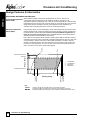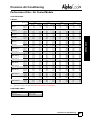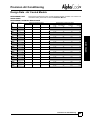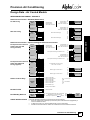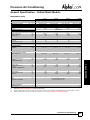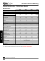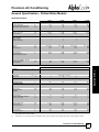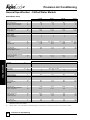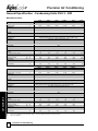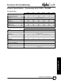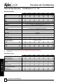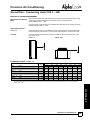
1
.COVER
Upflow – Precision Air Conditioning
8kW - 101kW
TECHNICAL MANUAL
-V
Precision Air Conditioning
AB OUT AIR ED AL E
About Airedale Products & Customer Services
WARRANTY
All AIAC products or parts (non consumable) supplied for installation within the UK mainland and
commissioned by an AIAC engineer, carry a full Parts & Labour warranty for a period of 12 months
from the date of commissioning or 18 months from the date of despatch, whichever is the sooner.
Parts or Equipment supplied by AIAC for installation within the UK or for Export that are properly
commissioned in accordance with AIAC standards and specification, not commissioned by an AIAC
engineer; carry a 12 month warranty on non consumable Parts only from the date of commissioning
or 18 months from the date of despatch, whichever is the sooner.
Parts or equipment installed or commissioned not to acceptable AIAC standards or specification
invalidate all warranty.
Warranty is only valid in the
event that
In the period between delivery and commissioning the equipment: is properly protected & serviced as
per the AIAC installation & maintenance manual provided where applicable the glycol content is
maintained to the correct level.
In the event of a problem being reported and once warranty is confirmed as valid under the given
installation and operating conditions, the Company will provide the appropriate warranty coverage
(as detailed above) attributable to the rectification of any affected Airedale equipment supplied
(excluding costs for any specialist access or lifting equipment that must be ordered by the customer).
Any spare part supplied by Airedale under warranty shall be warranted for the unexpired period of
the warranty or 3 months from delivery, whichever period is the longer.
To be read in conjunction with the Airedale Conditions of Sale - Warranty and Warranty Procedure,
available upon request.
CAUTION
Warranty cover is not a substitute for maintenance. Warranty cover is conditional to maintenance
being carried out in accordance with the recommendations provided during the warranty period.
Failure to have the maintenance procedures carried out will invalidate the warranty and any liabilities
by Airedale International Air Conditioning Ltd.
SPARES
A spares list for 1, 3 and 5 years will be supplied with every unit and is also available from our
Spares department on request.
TRAINING
As well as our comprehensive range of products, Airedale offers a modular range of Refrigeration
and Air Conditioning Training courses, for further information please contact Airedale.
CUSTOMER SERVICES For further assistance, please e-mail: [email protected] or telephone:
Custom er Services
UK Sales Enquiries
International Enquiries
Spares Hot Line
Airedale Service
Technical Support
Training Enquiries
+ 44 (0) 113 239 1000
+ 44 (0) 113 239 1000
+ 44 (0) 113 238 7878
+ 44 (0) 113 239 1000
+ 44 (0) 113 239 1000
+ 44 (0) 113 239 1000
[email protected]
[email protected]
[email protected]
[email protected]
[email protected]
[email protected]
For information, visit us at our Web Site: www.airedale.com
Legal Notices
AIAC Ltd endeavours to ensure that the information in this document is correct and fairly stated, but
none of the statements are to be relied upon as a statement or representation of fact. AIAC Ltd does
not accept liability for any error or omission, or for any reliance placed on the information contained
in this document.
The development of Airedale products and services is continuous and the information in this
document may not be up to date. It is important to check the current position with AIAC Ltd at the
address stated. This document is not part of a contract or licence unless expressly agreed.
No part of this document may be reproduced or transmitted in any form or by any means, electronic
or mechanical, including photocopying, recording, or information storage and retrieval systems, for
any purpose other than the purchaser’s personal use, without the express written permission of
AIAC Ltd.
ã 2012 Airedale International Air Conditioning Limited. All rights reserved. Printed in the UK.
2
Precision Air Conditioning
Technical Manual : 6258867 F 07/2012
Precision Air Conditioning
-V
CONTENT S
Contents
INDOOR UNIT
4
General Description ................................................................................................................4
Unit Identification.................................................................................................................... 4
Introduction ............................................................................................................................ 4
Standard Features ................................................................................................................. 5
Optional Extras - Energy Saving ............................................................................................ 8
Optional Extras - General....................................................................................................... 9
Dimensional & Installation Data ..........................................................................................14
Dimensions .......................................................................................................................... 14
Weights ................................................................................................................................ 16
Positioning ........................................................................................................................... 17
Controls .................................................................................................................................18
Sound Measurement Method...............................................................................................21
Design Features & Information............................................................................................22
Electronic Expansion Valves (EEV) ..................................................................................... 22
Condensate Pump (Optional Extra) ..................................................................................... 23
Rapid De-humidification ....................................................................................................... 24
Humidification ...................................................................................................................... 25
AIR COOLED (A & X) MODELS ............................................................................................26
Performance Data - Air Cooled Models ..............................................................................26
General Specification - Air Cooled Models ........................................................................28
Sound Data - Air Cooled Models .........................................................................................38
Design Data - Air Cooled Models ........................................................................................42
CHILLED WATER (CW) MODELS ........................................................................................51
Performance Data - Chilled Water Models .........................................................................52
General Specification - Chilled Water Models ...................................................................53
Sound Data - Chilled Water Models ....................................................................................59
Design Data - Chilled Water Models....................................................................................61
OUTDOOR UNIT (CUS & C)
65
General Description ..............................................................................................................65
Dimensional & Installation Data - Condensing Units CUS 3 - 30D.....................................69
Dimensional & Installation Data - Condensers C 11 - 50 ..................................................71
General Specification - Condensing Units CUS 3 - 30D....................................................72
General Specification - Condensers C 11 - 50 ...................................................................74
Sound Data - Condensing Units CUS 3 - 30D ....................................................................75
Sound Data - Condensers C 11 - 50 ....................................................................................76
Precision Air Conditioning
Technical Manual : 6258867 F 07/2012
3
Precision Air Conditioning
-V
Indoor Un it
General Description
GENERAL
UNIT IDENTIFICATION
ALPHACOOL PRECISION AIR CONDITIONING RANGE
V
Upflow Configuration
9 - 95
Model Size (Expressed as Nominal Cooling in kW)
A
Air Cooled Remote Condensing Unit
X
Air Cooled Remote Condenser
CW
Chilled Water
D
Dual Circuit
AT
Example
INTRODUCTION
Controls
V31AD-AT
Designed to provide environmental Precision air conditioning tolerances within the
conditioned space, such as Telecommunication Facilities, Computer Rooms and Clean
Rooms, the AlphaCool range is available with a choice of direct expansion air cooled or
chilled water and comprises 48models. Full function units provide full control of
temperature, humidity and filtration.
A full range of Airedale air cooled condensing units and condensers are available with the
direct expansion indoor units to provide matched system and Airedale air cooled water
chillers are available to complement the chilled water indoor units.
Free Cooling energy saving can be achieved using the chilled water unit matched with the
Airedale Ultima Free Cooling Chiller.
The unit is designed for the use of R407C, please refer to Optional Extras - General for
alternative refrigerants.
This manual covers the full range of Upflow configured models. For Downflow
-DF Technical Manual.
configured models, please refer to the
The Downflow configured models benefit from the addition of the energy saving Glycol
Free Cooling system, designed to reduce operating costs during cooler periods of
the year.
CE DIRECTIVE
Airedale certify that the equipment detailed in this manual conforms with the following
EC Directives:
Electromagnetic Compatibility Directive (EMC)
Low Voltage Directive (LVD)
Machinery Directive (MD)
Pressure Equipment Directive (PED)
2004/108/EC
2006/95/EC
89/392/EC in the version
2006/42/EC
97/23/EC
To comply with these directives appropriate national & harmonised standards have been
applied. These are listed on the Declaration of Conformity, supplied with each product.
4
Precision Air Conditioning
Technical Manual : 6258867 F 07/2012
Precision Air Conditioning
-V
General Description
STANDARD FEATURES
Unit cabinets are manufactured from galvanised sheet steel coated with epoxy baked
powder paint to provide a durable finish.
Standard unit colour is Light Grey (RAL 7035).
Internal strength and rigidity is provided by a welded space frame constructed of channel
profile folded steel.
Cabinets are lined internally with fire resistant 20mm foam (UL94 V0) for thermal and
acoustic insulation.
The cabinet doors are full height, hinged and key lock secured. Hinge arrangement allows
flexible door opening/removal for improved access.
Rubberised door seals reduce sound breakout and eradicate leakage.
For ease of maintenance, the front left hand control panel door may be safely opened
while the unit is in operation.
Unit design incorporates a series of M6/M8 fixings to the top face for offering up customer
ductwork, please contact Airedale for further details.
Sizes 9 - 55
As standard the units are supplied with a louvred grille to the cabinet doors for front return
air configuration in matching cabinet colour.
Size 65 - 95
As standard the units are supplied with an egg crate grille to the cabinet doors for front
return air configuration in matching cabinet colour.
Refer to Optional Extras - General for discharge and return options.
Evaporator
(A & X Models)
Large surface area coil(s) ideally positioned to optimise airflow and heat transfer,
manufactured from refrigeration quality copper tubes with mechanically bonded
aluminium fins.
The copper tube is internally rifled for improved heat transfer.
Fins are coated with a non-stick acrylic film (hydrophilic) which provides additional
corrosion protection and efficient surface water removal for improved performance.
The cooling coil is mounted over a full width stainless steel condensate tray.
Factory pressure tested to 40Bar.
Sweat copper pipe for brazed connection as standard.
Precision Air Conditioning
Technical Manual : 6258867 F 07/2012
5
GENERAL
Construction
-V
Precision Air Conditioning
General Description
GENERAL
STANDARD FEATURES
Chilled Water Coil
(CW Models)
Large surface area coil(s) ideally positioned to optimise airflow and heat transfer,
manufactured from refrigeration quality copper tubes with mechanically bonded
aluminium fins.
Fins are coated with a non-stick acrylic film (hydrophilic) which provides additional
corrosion protection and efficient surface water removal for improved performance.
Coil headers are circuited to ensure low water pressure drops.
The cooling coil is mounted over a full width stainless steel condensate tray.
For control of water flow, a 3 port, raise/lower type, modulating mixing control valve is
fitted as standard.
Maximum operating pressure 10Bar. Factory pressure tested to 20Bar.
Sweat copper pipe for brazed connection as standard. Optional threaded connections
available refer to General Specification - Chilled Water Models.
Fan & Motor Assembly - Standard
Sizes 9 - 19
(Direct Drive)
Units utilise a double inlet, forward curved, direct drive centrifugal fan with integral shaft
mounted motor which is statically and dynamically balanced for quiet operation. Impellers
and casings are galvanised for protection against corrosion. The integral motor runs in
sealed for life, lubricated bearings and features automatic thermal overload protection.
Fan speed, airflow and external static pressure are controlled by the use of a voltage
controller via the microprocessor display keypad which maintains optimum performance
and offers easy on site adjustment.
Adjustable by increments of 0.1 VDC between 2 - 10 VDC.
Sizes 23 - 95
(Belt & Pulley)
Double inlet forward curved centrifugal fan(s) with galvanised impellers and casing.
Mild steel fan shaft with lifetime lubricated ball bearings.
Fan and drive assembly design is based on a minimum of 25,000 hours life expectancy.
Each fan assembly separately driven by a high efficiency air cooled motor through a
pulley and ‘V’ belt drive. The complete motor assembly is mounted on a fully adjustable
platform for belt tensioning. Motor specification conforms to IE2 (EFF1).
Fan motors up to 2.2kW use adjustable pitch pulleys on the motor with a fixed pitch pulley
on the fan shaft, 3kW fan motors and above use fixed pitch pulleys to both the fan motor
and fan shaft to vary air volumes.
Fan(s) from 4kW and above have twin belt drives and plummer block bearings.
6
Precision Air Conditioning
Technical Manual : 6258867 F 07/2012
Precision Air Conditioning
-V
General Description
STANDARD FEATURES
An adjustable differential pressure switch activates a visual alarm at the status panel and
breaks the power supply in the event of a fan or motor failure.
Compressor
Compressor(s) are mounted on the base via the use of vibration isolators. Each
compressor is designed for use with R407C refrigerant.
(X Models)
Sizes 9, 13, 19, 23D & 41D
Utilise hermetic scroll compressors fitted as standard with:
·
Internal thermal motor protection
Sizes 16, 31 & 35
Utilise hermetic scroll compressors fitted as standard with:
·
Internal thermal motor protection
·
ECA Approved
Sizes 23, 25, 50D, 55D, 65D, Utilise hermetic scroll compressors fitted as standard with:
80D & 90D
·
Internal thermal motor protection
·
Sight glass
·
Internal thermal motor protection
·
High discharge gas thermostat
·
Oil sump heaters, to guard against refrigerant migration and to eliminate oil foaming
on start-up
Refrigeration
Each refrigeration circuit features as standard:
A Models
·
·
·
·
Externally equalised thermostatic expansion valve (TEV)
Sight glass (loose)
Filter drier (loose) (supplied with Airedale matched outdoor units)
Holding charge of inert gas
X Models
·
·
·
·
·
·
Externally equalised thermostatic expansion valve (TEV)
Sight glass (loose)
Filter drier (loose) (supplied with Airedale matched outdoor units)
Low pressure switch - manual reset
High pressure switch - manual reset
Holding charge of inert gas
Filters
97mm pleated disposable panel filters in a rigid frame. Conform to BS EN 779-G4.
Access and removal from unit front.
An adjustable diaphragm pressure switch is fitted across the filter assembly to monitor
pressure drop, which will initiate a filter dirty alarm.
Precision Air Conditioning
Technical Manual : 6258867 F 07/2012
7
GENERAL
Airflow Switch
-V
Precision Air Conditioning
General Description
GENERAL
STANDARD FEATURES
Electrical
The control panel contains the necessary fan motor contactors and overloads,
compressor starter (X type units) contactors, transformer, sub circuit protection, volt free
contacts, mains and inter-connecting terminals. The panel is situated within the cabinet
and is hinged for easy access to other components within the unit. The electrical control
panels are wired to the latest European standards and codes of practice.
Main Electric Isolator
To ensure complete unit isolation of the electrical panel during adjustment and
maintenance a door interlocking isolator is provided as standard.
Controls
microprocessor controller which offers powerful
Units are fitted with the
analogue and digital control to meet a wide range of monitoring and control features
including a real time clock and a communication port plus networking and
BMS connections.
A 4 x 20 character backlit LCD door mounted display keypad assembly is used to view
the unit status and allow operator adjustment.
For further details, please refer to the Controls section.
Head Pressure Control Stand Alone
Refer to the Outdoor Unit section, General Description.
OPTIONAL EXTRAS - ENERGY SAVING
Electronic Expansion
Valves (EEV)
(A & X Models)
Electronic expansion valves differ to the normal thermostatic expansion valves in their
ability to maintain control of the suction superheat at reduced head pressures. This can
lead to significant energy savings particularly at reduced loading and low ambient
temperatures.
EEV step position, superheat setpoint, head pressure set point and other features can be
viewed and adjusted via the microprocessor display keypad.
Factory fitted, for full details refer to Design Features & Information.
CAUTION
Head Pressure Control Intelligent
(A & X Models)
As standard, the Intelligent Head Pressure Control option is included when the EEV
option is selected.
As an alternative to the stand alone head pressure control fitted to the outdoor
condensing unit or condenser, the system can be fitted with a voltage regulating fan
speed controller which allows set point adjustment and system monitoring via the indoor
microprocessor controller.
unit
A pressure transducer is fitted to the liquid line which in turn feeds back the head
pressure to the microprocessor. The condenser fan speed can then modulate via the
controller to provide optimum control under varying ambient conditions. The head
pressure can be monitored via the display keypad.
With the head pressure factory set to 14 Barg (203 psig) part load, EER values are
significantly improved, which in turn lowers energy consumption.
8
Precision Air Conditioning
Technical Manual : 6258867 F 07/2012
Precision Air Conditioning
-V
General Description
OPTIONAL EXTRAS - GENERAL
This feature is included as part of the Intelligent Head Pressure Control option, as
detailed above and comes as standard when the EEV options is selected.
(A & X Models)
Specifically designed for night time operation as optimum low noise levels are achieved
with reduced ambient temperature and room loads, this feature is also ideal for residential
and other outdoor noise critical applications.
Initiated by setting the microprocessor programmable time clock, the head pressure set
point changes from the standard 14 Barg (203 psig) to 22 Barg (319 psig), reducing the
outdoor unit fan speed and corresponding operating sound levels.
Humidifier - Intelligent
Modulation
Humidification is provided by an electrode boiler. The sealed humidifier design ensures
that only clean sterile steam is supplied to the conditioned area and corrosive salts and
minerals are held in the disposable bottle. The steam is distributed through a sparge pipe
fitted to the coil assembly.
Featuring modulating capacity output control as standard, the system provides
continuous modulation of steam output in response to a proportional control signal. The
output control range is 20%-100% of the humidifier rated value and is designed to give an
approximate steam output of +/- 3%, at the sensor, thus ensuring precise control of the
conditioned space.
The cylinder operating life time is automatically optimised via the integrated water
controls monitors and
conductivity sensor, which combined with the
regulates the water refill cycle to reduce excessive salt deposits and the progressive wear
of the cylinder. For further details, refer to Design Features & Information.
All humidifier parameters and alarms are accessible and adjustable via the
microprocessor display keypad unit, main features include:
·
·
·
·
·
·
Supply water conductivity (mS/cm)
Actual steam output (kg/h)
Required steam output (kg/h)
Actual current rating (A)
Required current rating (A)
Status mode (Start Up, Running, Filling, Draining)
Precision Air Conditioning
Technical Manual : 6258867 F 07/2012
9
GENERAL
Low Noise Feature for
Condenser Fan
Precision Air Conditioning
-V
General Description
GENERAL
OPTIONAL EXTRAS - GENERAL
Water Conductivity &
Cylinder Type
Conductivity is a measure of the ability of water to pass an electric current, measured in
micro Siemens / centimetre (mS/cm). 3 different cylinders are available which correspond
to the supply water conductivity.
Matching the correct cylinder type with the conductivity of the supply water ensures
optimum performance and increases the life span of the cylinder.
1
2
3
Low Conductivity
Standard Conductivity
High Conductivity
(Soft Water)
- 100 to 350 mS/cm
(Moderate/Hard Water) - 350 to 750 mS/cm
(Very Hard Water)
- 750 to 1250 mS/cm
As standard the humidifier is fitted with the standard conductivity cylinder which covers
the majority of water supplies. Where the water conductivity is known, please specify at
order. For further details please contact Airedale.
Cleanable Humidifier
Cylinder
The humidifier can be fitted with a take apart cylinder enabling the bottle and the
electrodes to be cleaned and reused. The cylinder can typically be cleaned 3 times before
replacing either the electrodes or the entire cylinder.
The cleanable humidifier cylinders are available in 8kg and 15kg bottle sizes with
standard or high conductivity levels only. For further details please contact Airedale.
CAUTION
The supply water pressure to the humidifier assembly must be between 1 - 8 Barg.
Heating Options
Electric Heating
Multi-stage finned electric heating elements complete with auto and manual reset
overheat cut-out protection, phase balanced for increased efficiency.
or
Low Pressure Hot Water
A low pressure hot water coil constructed of refrigeration quality copper tube and
mechanically bonded aluminium fins can be factory fitted.
Frost protection is fitted to prevent freezing of the low pressure hot water coil assembly.
Proportional heating control is provided by a factory fitted 3 port, raise/lower type,
modulating valve.
10
Precision Air Conditioning
Technical Manual : 6258867 F 07/2012
Precision Air Conditioning
-V
General Description
OPTIONAL EXTRAS - GENERAL
97mm, pleated disposable panel filters conforming to BS EN 779-F6. Protected by 22mm,
disposable, synthetic type pre filters conforming to BS EN 779 G3.
(Except Sizes 35, 55, 90 &
95)
To maintain design ESP, fan selection may alter with high efficiency filters, please refer to
General Specification.
Fan & Motor Assembly
Where higher external static pressure is required units can be fitted with the traditional
belt and pulley, separate fan and motor assembly.
(Sizes 9 - 19)
Double inlet forward curved centrifugal fan(s) with galvanised impellers and casing.
Mild steel fan shaft with lifetime lubricated ball bearings.
Fan and drive assembly design is based on a minimum of 25,000 hours life expectancy.
Each fan is separately driven by a high efficiency air cooled motor through a pulley and
‘V’ belt drive. The complete motor assembly is mounted on a fully adjustable platform for
belt tensioning. Motor specification conforms to Efficiency Class 2 (EFF1 (IE2)).
Fan motors up to 2.2kW use adjustable pitch pulleys on the motor with a fixed pitch pulley
on the fan shaft, 3kW fan motors and above use fixed pitch pulleys to both the fan motor
and fan shaft to vary air volumes.
Fan(s) from 4kW and above have twin belt drives and plummer block bearings.
Larger & Next Larger
Fan Motor
Motor specification conforming to Efficiency Class 2. For applications where higher static
air pressures are required, a larger motor size can be fitted to replace the standard motor.
High Efficiency Fan
Motors
Belt and pulley fan and motor assemblies only.
High efficiency motors can be fitted that operate at lower running currents providing the
benefit of lower running costs.
Conform to Efficiency Class 1 (EFF1) according to EN60034-2.
For technical data, please contact Airedale.
Higher External Static
(Sizes 9 - 55)
A higher external static can be achieved on standard configuration front return air models
by replacing the louvred front grille with an egg crate type, for technical data please refer
to Airedale.
Precision Air Conditioning
Technical Manual : 6258867 F 07/2012
11
GENERAL
High Efficiency
& Pre Filters
-V
Precision Air Conditioning
General Description
GENERAL
OPTIONAL EXTRAS - GENERAL
Fan & Motor Anti
Vibration Mounts
Spring type vibration isolators can be fitted between the fan and motor mounting plate
and the unit chassis.
Condensate Pump
The condensate pump has a 6 litre reservoir with a capacity of 5 l/m at a head of 10.8m
and is mounted in the unit base, for pump performance; refer to Design Features &
Information.
On units with optional base return air, the condensate pump is supplied loose and must
be mounted in the floor void beneath the service connections.
Water Detector
2 methods are available:
1 A solid state (probe) sensor is supplied loose for remote mounting on site.
2 Tape suitable for sensing water droplets is supplied loose for remote mounting on
site. Standard tape length 10m.
Firestat
Installed in the return air stream to shut down the unit in the event of an unusually high
return air temperature.
Smoke Detector
Supplied loose for remote mounting to shut down the unit and activate the alarm upon
sensing the presence of smoke.
Take Apart Structure
If required, units can be supplied in 2 pieces for sites where access is restricted, the
overall height of the unit increases to 2040mm, refer to Dimensional & Installation Data in
this section.
Return Air Configuration Standard unit configuration is front return air, the following options are available, please
specify at order:
A, X & CW Models
(Sizes 9 - 95)
Rear return air.
A & CW Models
(Sizes 19 - 95)
Base return air.
Open & Enclosed
Floorstand
Open or enclosed floorstands are available, complete with adjustable feet and floor tile
lip. The height of the floor stand can be specified at the time of order.
12
Precision Air Conditioning
Technical Manual : 6258867 F 07/2012
Precision Air Conditioning
-V
General Description
OPTIONAL EXTRAS - GENERAL
Constructed to match main cabinet design Light Grey (RAL 7035) available:
·
Front only or 3 way discharge air
·
Egg crate or double deflection grilles
Discharge Air
Configuration
Standard configuration is top forward air discharge. Top reverse air discharge is
available, please specify at order.
Ceiling Duct Extension
Straight and ‘L’ shaped duct extensions up to a height of 1350mm constructed and
finished to match the unit are available.
GENERAL
Discharge Air Plenums
For extensions greater than 1350mm, please contact Airedale.
Height, please specify at order.
Chilled Water Bypass
Balancing Valves
Bypass balancing valves can be fitted to aid commissioning and unit operation by
creating the same pressure drop through the bypass as through the chilled water coil.
2 Port Chilled Water
Control Valve
For systems with variable speed pumps and water flow, a 2 port control valve can be
fitted in place of the standard 3 port valve.
Threaded Connection
BSP brass male taper threaded connections can be factory fitted.
(CW Models)
Sub Fusing
(A & X Models)
The electrical mains supply for the system’s outdoor unit(s) can be supplied via the
indoor unit.
Alternative Refrigerant
For applications outside the EU, units can be supplied for use with R22, please specify
at order.
Export Packing
Units can be supplied packed inside a wooden crate or case to provide additional
protection during transportation, (not required for container delivery).
Precision Air Conditioning
Technical Manual : 6258867 F 07/2012
13
Precision Air Conditioning
-V
Dimensional & Installation Data
MODELS: A, X OR CW - STANDARD AIRFLOW CONFIGURATION (MM)
A
B
E
A
B
A
B
C
D
A
B
800
9 - 16
D
(1)
19 - 35
41 - 55
1450
G
65 - 95
A, X & CW
A, X & CW
A, X & CW
A, X & CW
A, X & CW
CW
G
mm
mm
mm
mm
mm
mm
2000
G
HxDxW
1940 x 800 x 900
1940 x 800 x 1450
1940 x 800 x 1450
1940 x 800 x 2000
1940 x 800 x 2550
1940 x 800 x 2550
2550
G
A(4)
282 (258)
282 (258)
596 (N/A)
478 (N/A)
698 (N/A)
698 (N/A)
B(4)
337 (311)
401 (477)
477 (N/A)
377 (N/A)
477 (N/A)
477 (N/A)
C
350
350
350
D
377
477
477
E(4) & (5)
112 ( 82)
112 (70)
70 (N/A)
82 (N/A)
82 (N/A)
82 (N/A)
Unit diagrams can be supplied on request, please contact Airedale.
(1)
(2)
(3)
(4)
(5)
(6)
14
(2)
(3)
900
V 9 - 16
V 19
V 23 - 35
V 41 - 55
V 65 - 90
V 95
C
F
1940
GENERAL
DIMENSIONS
Standard Forward Airflow Direction.
Optional Reverse Airflow Direction.
Models sizes 9 - 55 have louvred front return grilles and Models 65 - 95 have egg crate front return grilles as standard.
Figures in brackets represent position of Fan Discharge Aperture when Larger Fan Motor Option is fitted.
Dimension will vary with some optional extras, please refer to Airedale.
Dimension represents the area in the base available for customer connections.
Precision Air Conditioning
Technical Manual : 6258867 F 07/2012
F(4)
295 (344)
348 (407)
407 (N/A)
407 (N/A)
407 (N/A)
407 (N/A)
G(6)
180
280
280
280
280
280
H
900
1450
1450
2000
2550
2550
Precision Air Conditioning
-V
Dimensional & Installation Data
DIMENSIONS
1280
1
760
2040
(1)
A, X & CW
A, X & CW
AD, XD & CW
AD, XD & CW
AD, XD & CW
CW
mm
mm
mm
mm
mm
mm
A
900
1450
1450
2000
2550
2550
V 9 - 23
V 23 - 55
V 65 - 90
V 95
A, X & CW
AD, XD & CW
AD, XD & CW
CW
mm
mm
mm
mm
A
350
450
550
550
V 9 - 16
V 19 - 23
V 23 - 35
V 41 - 55
V 65 - 90
V 95
A, X & CW
A, X & CW
AD, XD & CW
AD, XD & CW
AD, XD & CW
CW
mm
mm
mm
mm
mm
mm
A
820
1370
1370
1920
2470
2470
V 9 - 16
V 19 - 25
V 23 - 35
V 41 - 55
V 65 - 90
V 95
GENERAL
2 Way Optional Split Case (mm)
2
800
A=
(1)
(2)
Note additional height.
Split case assembly/disassembly instructions supplied with unit.
Optional Discharge Air Plenum
A=
Optional Rear Return Air Aperture
40 (2)
557 (657)
(1)
51 (2)
40
(2)
(1)
(2)
A=
40
(2)
Figures in brackets represent split case optional dimensions only.
Dimensions represent the usable area for duct flange attachment.
Precision Air Conditioning
Technical Manual : 6258867 F 07/2012
15
Precision Air Conditioning
-V
Dimensional & Installation Data
GENERAL
WEIGHTS
1 PIECE DELIVERY
V9A
V13A
V16A
V19A
V23A
V25A
V23AD
V31AD
V35AD
V41AD
V45AD
V50AD
V55AD
V65AD
V80AD
V90AD
V9X
V13X
V16X
V19X
V23X
V25X
V23XD
V31XD
V35XD
V41XD
V45XD
V50XD
V55XD
V65XD
V80XD
V90XD
V9CW
V13CW
V16CW
V19CW
V23CW
V25CW
V31CW
V35CW
V41CW
V45CW
V50CW
V55CW
V65CW
V80CW
V90CW
V95CW
kg
kg
kg
kg
kg
kg
kg
kg
kg
kg
kg
kg
kg
kg
kg
kg
kg
kg
kg
kg
kg
kg
kg
kg
kg
kg
kg
kg
kg
kg
kg
kg
kg
kg
kg
kg
kg
kg
kg
kg
kg
kg
kg
kg
kg
kg
kg
kg
Total Machine
Total Machine
266
270
276
341
356
366
394
400
428
546
576
552
588
617
632
679
286
291
296
396
451
469
466
482
516
616
712
674
726
816
843
924
251
256
256
332
370
374
515
550
542
568
557
576
635
659
686
704
286
290
297
360
376
386
415
421
449
586
616
589
625
661
697
744
290
300
305
406
477
495
503
519
553
637
733
730
782
826
863
944
255
260
260
336
375
378
521
556
547
573
566
585
644
673
699
717
OPTIONAL PLENUM
V 9 - 16
V 19 - 25
V 23 - 35
V 41 - 55
V 65 - 90
V 95
16
A, X & CW
A, X & CW
AD, XD & CW
AD, XD & CW
AD, XD & CW
CW
kg
kg
kg
kg
kg
Total Plenum Weight
26
36
41
52
70
70
Precision Air Conditioning
Technical Manual : 6258867 F 07/2012
SPLIT DELIVERY
Split Module 1
(Fan/Coil Section)
205
208
212
258
269
276
297
301
322
419
450
422
458
472
490
523
176
181
185
260
306
318
326
332
361
363
418
417
446
470
491
537
183
186
186
241
268
271
373
398
383
409
378
397
460
473
492
505
Split Module 2
(Filter Section)
81
83
84
103
107
110
118
120
128
167
167
168
168
189
206
220
114
118
120
146
171
178
177
187
193
274
315
314
336
357
373
408
73
74
74
96
107
108
148
158
164
164
188
188
184
199
207
213
Precision Air Conditioning
-V
Dimensional & Installation Data
POSITIONING
Standard Front Return
(1)
(2)
The unit is designed for use with
either ducted discharge or a plenum.
If neither is used, protection from
rotating parts in the form of a grille must
be used on the discharge air outlet.
Placing objects near an unguarded fan
may cause injury.
A
Optional Base or Rear
Return
(1)
(2)
(6)
V 9 - 16
V 19 - 35
V 41 - 55
V 65 - 90
V 95
(1)
(2)
(3)
(4)
(5)
(6)
(7)
A, X & CW
A, X & CW
A, X & CW
A, X & CW
CW
mm
mm
mm
mm
mm
A
900
1450
2000
2550
2550
B
900
900
900
900
900
C - FLOORSTAND(7)
Min 350
(+ 50mm Feet
Adjustable +/- 20mm)
Reversed discharge air.
Forward discharge air.
Shaded area indicates minimum service and maintenance requirements
Shown with optional open floor stand.
Optional base return.
Optional rear return.
Dimension C denotes recommended minimum floorstand height, refer to Airedale for special applications.
Precision Air Conditioning
Technical Manual : 6258867 F 07/2012
17
GENERAL
Models A, X & CW
Precision Air Conditioning
-V
Controls
GENERAL
GENERAL
As standard the units are supplied with an
connected to a 4x20 back-lit LCD display keypad.
microprocessor controller
The
microprocessor controller can be linked together locally to provide
run/standby operation. Windows based supervisor software is also available for local or
remote networking. This modular approach provides great flexibility while at the same
time reducing installation and maintenance costs.
A real time clock card is fitted as standard to provide date and time stamping on alarms.
The display keypad features a simple array of keys to navigate through the in
built menus.
TEMPERATURE
CONTROL
A combined temperature and humidity sensor is mounted in the return air with an option
for remote mounting within the conditioned space.
The temperature sensor is a NTC type thermistor accurate up to +/- 0.25°C and the
humidity sensor accurate to +/- 3%.
The Airedale microprocessor senses the Return Air conditions and maintains the Return
air Temperature and Humidity conditions by controlling cooling, heating, humidification
and dehumidification outputs accordingly. The supply air temperature is monitored by the
controller providing an option of Supply Air temperature limiting.
The microprocessor monitors and displays the following values:
MONITORING
·
·
·
·
·
Return Air Temperature
Return Air Humidity
Supply Air Temperature
Condensing Pressure
(Optional on [DX] units only)
Glycol Temperature
(Glycol free cooling units only)
·
·
Chilled Water Flow Temperature
(Chilled Water units only)
Chilled Water Return Temperature
(Chilled Water units only)
ALARM HANDLING
An Visual alarm will be generated under the following conditions:
·
Return air temperature high limit
·
Low pressure trip (DX units only)
·
Return air temperature low limit
·
Electric Heating Overheat cut-out
·
Return air humidity high limit
·
Filter change alarm
·
Return air humidity low limit
·
Manual override
·
Supply air temperature high limit
·
Fire/smoke alarm
·
Supply air temperature low limit
·
Water Flood
·
Glycol temperature low limit
·
Power fail reset
(DX free cooling units only)
·
Communications failure
·
Frost protection low limit
·
Humidifier alarm (low production, no
(LPHW option only)
water supply etc)
·
Airflow failure
·
Maintenance - fan and compressor
·
Compressor failure (DX units only)
(once hours run limit exceeded)
ALARM LOG
The controller logs and allows viewing of the last 100 conditions recorded in descending
chronological order through the keypad display
18
Precision Air Conditioning
Technical Manual : 6258867 F 07/2012
Precision Air Conditioning
-V
Controls
STANDARD FEATURES
The default screen shows the unit status and room condition (°C/RH %) without the need
for interrogation and an easy to navigate menu structure for further interrogation
and adjustment.
Password Protection
The control system integrity can be maintained by restricting access with a password
PIN number.
CAUTION
IMPORTANT: To change the PIN number; please contact Airedale at time of order
with the preferred 4 digit number.
Remote On/Off
Terminals for interlocking are provided to enable or disable the unit remotely.
Fire Shut Down
Terminals for interlocking are provided to shut down the unit in the event of fire.
Compressor Anti-Cycle
Control
Programmed to provide automatic anti-cycling delays of up to 10 starts per hour with a
minimum off time of 3 minutes.
Compressor Rotation
On dual and triple circuit units the controller is programmed to provide automatic
compressor rotation to ensure equal compressor running times. In the event of a
compressor fault the controller is programmed to automatically select the next
compressor in order of running hours.
Compressor Hours Run
Log & Reset
Allows the user to monitor the running times of each compressor and reset
after maintenance.
Evaporator Fan Hours
Run Log & Reset
Allows the user to monitor the running times of the evaporator fans and reset
after maintenance.
Networking
A Local Area Network (
) can be used to connect upto 6 units to offer
intercommunication and Duty/Standby control. This also allows the connection of
computers, printers and modems on the same communications ring. For further details,
please contact Airedale Controls.
CAUTION
When adding to an existing network, please consult Airedale to ensure
strategy compatibility.
Precision Air Conditioning
Technical Manual : 6258867 F 07/2012
19
GENERAL
User Friendly Display
Keypad
-V
Precision Air Conditioning
Controls
GENERAL
STANDARD FEATURES
Duty/Standby Operation
The controller enables units to operate in run/standby mode, with up to 6 units networked
together, without the need for additional hardware or controllers. Standby units can be
configured to start when the run unit has a critical alarm and/or a high/low return air
temperature alarm.
Duty Rotation
Networked units can be configured to duty rotate, providing equal hours run of fans
and compressors.
(Network Units)
Head Pressure Control
and Condenser Fan
Speed Controller
Each refrigerant circuit is fitted with condenser pressure transducers and a modulating
condenser fan speed controller to allow the designed head pressure to be monitored and
maintained under varying ambient conditions. Condenser fan speed control settings are
adjustable via the display keypad.
As standard, the Intelligent Head Pressure Control option is included when the EEV
option is selected.
NTC type thermistors are provided to monitor the chilled water entering and
Chilled Water
Temperature Monitoring leaving temperatures.
Evaporator Fan Speed
Controller
Evaporator fan speed control is easily set via the display keypad and can be
incrementally increased or decreased to meet on site airflow requirements.
(Sizes 9 - 19)
Occupied / Unoccupied
Set Points
Occupied and unoccupied set points are provided for temperature, humidity and head
pressure control settings.
OPTIONAL EXTRAS
LPHW Frost Protection
(DX units with LPHW
option)
The frost protection thermostat provided, is mounted between the DX and LPHW coils
and has a fixed 3°C setting to disable DX cooling.
BMS Interface Card
Controlled units to be interfaced with most BMS, factory fitted,
Enables
please contact Airedale.
A wide range of protocols can be accommodated through the use of interface devices.
Available as a standard option are: ModBus/Jbus, Carel and Trend.
For interfaces such as SNMP, LonWorks, Metasys and BACnet, please contact Airedale.
Also available is Airedale’s own supervisory plug-in BMS card pCOWEB.
Based on Ethernet TCP/IP secure technology with SNMP features.,
Requires no proprietary cabling or monitoring software and supplied pre programmed with
an IP address for ease of set up.
GSM Modem Kit
20
Allows remote alarm monitoring by sending alarm text messages to a nominated mobile
phone, factory set.
Precision Air Conditioning
Technical Manual : 6258867 F 07/2012
Precision Air Conditioning
-V
Sound Measurement Method
MEASUREMENT OF
SOUND DATA
All Sound Power Levels quoted are calculated from measured sound intensity according
to BS EN ISO9614 Part 1 : 1995.
SEMI HEMISPHERICAL
Sound Pressure Levels are calculated from sound power using the semi-hemispherical
method where the noise source is in junction with 2 boundaries i.e. the floor and 1 wall.
FREE FIELD
For comparison, the semi hemispherical figures can typically be reduced by 3dB to
provide free field conditions.
IMPORTANT
The sound data quoted is based on the unit having return air application with
ducted discharge air.
Case breakout sound data is therefore independent of the discharge air
sound data.
For non-ducted discharge air applications, the overall case breakout sound levels
may increase, due to the discharge sound being predominant.
Within the conditioned space, sound from in-room ducted discharge air grilles and
other equipment will contribute to the overall sound level and should therefore be
considered as part of sound calculations.
Specialist acoustic advice is recommended for noise critical applications.
Front Return Air Configuration
(3)
Rear / Base Return Air Configuration
(Optional)
(4)
(2)
(3)
(1)
(1)
(1)
(2)
(3)
Return Air
Case Breakout & Front Return Air
Discharge Air
(2)
(1)
(2)
(2)
(4)
Return Air Option or
Base Return Air Option
Case Breakout
Discharge Air
Precision Air Conditioning
Technical Manual : 6258867 F 07/2012
21
GENERAL
All sound data quoted has been measured in the third-octave band limited values, using a
Real Time Analyser calibrated sound intensity meter in accordance with BS EN ISO9614
Part 1 : 1995.
Precision Air Conditioning
-V
Design Features & Information
Thermostatic Expansion Whilst offering versatile control at the full design duty of the unit, TEVs do not
automatically optimise themselves to all operating conditions. Therefore, if the
Valves (TEV)
refrigeration system is operating at 40% or 50% of full load, especially at a lower ambient
temperature than that for which the valve was sized, the conventional TEV must have the
design head pressure available to ensure good refrigerant control. Maintaining an
artificially high condensing pressure is normal in conventional systems.
Electronic Expansion
Valves (EEV)
Using an EEV allows for good refrigeration control whilst operating at part load and lower
ambient conditions with a reduced condensing pressure. By fitting an EEV and adjusting
the head pressure control setting an increase in the system EER (Energy Efficiency
Ratio) of up to 30% can typically be seen. The Mollier diagram shown below helps to
illustrate how this increase in efficiency is achieved.
Dew
Bubble
EEV’s differ to normal thermostatic expansion valves in their ability to maintain control of
refrigerant flow and the suction superheat at reduced head pressures. The turn-down rate
of a typical EEV is superior to that of it’s thermostatic equivalent, such that a reduced
optimum condensing pressure can be maintained at low compressor load. However low
the load is on the compressor, from zero to 100%, there will not be a problem with turn
down, even down to 10% of the valves rated capacity.
Reduced Condensing
Pressure
Pressure (Bara)
2
1
2
3
4
1
3
4
Compression
Condensation
Expansion
Evaporation
Enthalpy (kJ/kg)
Reduction in
Compressor
Input Power
Evaporating Pressure
Increase in
Cooling Duty
GENERAL
ELECTRONIC EXPANSION VALVES (EEV)
Key
Cooling Cycle @ 22°C ambient with a conventional TEV fitted.
Cooling cycle @ 22°C ambient, demonstrating a typical EEV condensing
temperature taking full advantage of lower ambient air temperatures (below 35°C).
22
Precision Air Conditioning
Technical Manual : 6258867 F 07/2012
Precision Air Conditioning
-V
Design Features & Information
CONDENSATE PUMP (OPTIONAL EXTRA)
The following illustrates the TOTAL static (head) pressure available. The system
horizontal pipe losses and vertical lift should be factored in when calculating the
condensate pump performance.
GENERAL
12
10
8
Head (m)
Performance
6
4
2
0
5
7
9
11
13
15
Pump Flow Rate (l/min)
Precision Air Conditioning
Technical Manual : 6258867 F 07/2012
23
Precision Air Conditioning
-V
Design Features & Information
Controlled by the
microprocessor, electronic expansion valves are unlike
their conventional thermostatic counterparts in that they can modulate independently of
controller to
the suction line temperature. This unique feature allows the
(Only available with
raise
the
superheat
set-point,
in
turn
dropping
the
evaporating
temperature
to a point at
Electronic Expansion Valves
which considerable de-humidification takes place.
(EEV))
Effect of Superheat on
Evaporating Temperature
and SHR
(1)
8
7
6
5
4
3
2
0
5
10
15
Superheat Set Point (°C)
(1)
(2)
24
Normal Operating Conditions
Rapid De-hum Condition
Precision Air Conditioning
Technical Manual : 6258867 F 07/2012
(2)
1.00
1.00
0.98
0.98
0.96
0.96
0.94
0.94
0.92
0.92
0.90
0.90
0.88
0.88
0.86
0.86
0.84
0.84
0.82
0.82
20
Sensible Heat Ratio
This increase in the de-humidification rate means that time taken to reduce the room
humidity to the required level is drastically decreased, along with the energy required to
do so. The graph below shows the typical effect that the superheat set-point has on the
evaporating temperature and sensible heat ratio.
Mean Evaporating
Temperature (°C)
GENERAL
RAPID DEHUMIDIFICATION
Precision Air Conditioning
-V
Design Features & Information
HUMIDIFICATION
In a humidifier with electrodes, steam is produced by passing a current between electrode
plates to generate heat. The higher the current being passed between the electrodes, the
greater the quantity of steam that is produced.
To modulate the rate of steam production, this system varies the level of water within the
cylinder, thereby increasing the immersion level of the electrodes and the current being
passed between them. The more conducting area that is available to pass current
between the electrodes, the larger the amount of steam that is produced.
controller, the water level is varied so that the level of
Modulated by the
steam being produced ensures that the room humidity set-point is continually maintained
within a tight tolerance.
Optimised Lifetime
The life span of the Airedale humidification system is optimised by the inclusion of a water
conductivity sensor into the bottle feed. This sensor determines the conductivity level of
software,
the supply water and by using an algorithm embedded in the
determines the frequency that the bottle should be drained.
EXAMPLE: As liquid water is boiled off into steam, mineral deposits are left in solution increasing the
(Optimised Lifetime with conductivity of the water. To counter this, the intelligent software increases the frequency
High Water Conductivity of drain meaning that the replenishing supply water keeps the concentration of minerals
Supply) diluted. By maintaining an acceptable mineral concentration, the bottle life span
is maximised.
Precision Air Conditioning
Technical Manual : 6258867 F 07/2012
25
GENERAL
Control Principles
Precision Air Conditioning
-V
AIR C OOLED (A & X) MOD ELS
Performance Data - Air Cooled Models
COOLING DUTIES
A Models
Cooling Capacity (1)
V9A / CUS3
V13A / CUS4
V16A / CUS5
AIR COOLED
V19A / CUS6
V23A / CUS7.5
V25A / CUS8.5
V23AD / CUS4 x 2
V31AD / CUS5 x 2
V35AD / CUS5.5 x 2
V41AD/ CUS6 x 2
V45AD / CUS6.5 x 2
V50AD / CUS7.5 x 2
V55AD / CUS8.5 x 2
V65AD / CUS10 x 2
V80AD / CUS12 x 2
V90AD / CUS30D
TC = Total Cooling
(1)
26
Ambient
Air On °C DB
/%RH
22 / 50
24 / 45
26 / 40
22 / 50
24 / 45
26 / 40
22 / 50
24 / 45
26 / 40
22 / 50
24 / 45
26 / 40
22 / 50
24 / 45
26 / 40
22 / 50
24 / 45
26 / 40
22 / 50
24 / 45
26 / 40
22 / 50
24 / 45
26 / 40
22 / 50
24 / 45
26 / 40
22 / 50
24 / 45
26 / 40
22 / 50
24 / 45
26 / 40
22 / 50
24 / 45
26 / 40
22 / 50
24 / 45
26 / 40
22 / 50
24 / 45
26 / 40
22 / 50
24 / 45
26 / 40
22 / 50
24 / 45
26 / 40
25°C
TC (kW)
9.0
9.2
9.5
11.5
12.0
12.3
14.0
14.4
15.0
17.6
18.0
18.6
20.8
21.7
22.5
26.1
27.1
28.1
21.7
22.5
23.3
26.2
27.4
28.6
28.9
30.3
31.4
39.6
41.1
42.5
42.4
44.1
45.8
42.3
44.2
46.2
51.5
53.9
56.3
58.7
60.9
63.2
72.8
75.4
78.5
88.7
91.8
94.9
SC (kW)
8.1
8.7
9.2
10.5
11.4
12.1
12.9
13.9
14.7
14.7
16.0
17.3
19.7
21.1
22.4
23.8
25.6
27.4
20.6
22.0
23.3
25.2
26.9
28.6
27.9
29.7
31.4
37.5
40.1
42.3
40.2
42.9
45.4
40.9
43.8
46.2
48.7
52.5
56.1
55.6
59.6
63.2
68.2
72.9
77.6
80.5
87.0
92.6
30°C
TC (kW)
8.6
8.8
9.1
11.0
11.4
11.8
13.4
13.9
14.4
16.9
17.3
17.9
20.0
20.9
21.7
25.2
26.1
27.2
20.7
21.5
22.4
25.2
26.4
27.6
27.9
29.2
30.4
37.0
38.5
39.9
39.8
41.4
43.1
39.6
41.6
43.5
48.6
50.9
53.2
55.0
57.1
59.4
68.4
70.9
73.9
83.3
86.3
89.3
SC (kW)
7.9
8.4
8.9
10.2
11.0
11.7
12.6
13.5
14.3
14.4
15.7
16.9
19.2
20.5
21.6
23.3
25.0
26.6
20.0
21.2
22.4
24.4
26.1
27.6
27.0
28.8
30.4
35.5
38.0
39.9
38.1
40.6
42.9
38.7
41.4
43.5
46.3
49.8
53.2
52.6
56.4
59.4
64.8
69.1
73.5
76.7
82.6
87.8
SC = Sensible Cooling
Deduct fan motor gain for nett duties, refer to General Specification - Air Cooled Models.
Precision Air Conditioning
Technical Manual : 6258867 F 07/2012
35°C
TC (kW)
8.2
8.4
8.7
10.5
10.9
11.2
12.9
13.4
13.9
16.2
16.6
17.2
19.2
20.0
20.8
24.3
25.2
26.2
19.8
20.5
21.4
24.2
25.4
26.6
26.8
28.0
29.4
34.5
36.0
37.3
37.3
38.8
40.4
37.1
38.9
40.8
45.7
48.0
50.2
51.4
53.4
55.7
64.1
66.6
69.4
78.0
80.8
83.7
SC (kW)
7.6
8.1
8.6
9.9
10.6
11.2
12.2
13.0
13.8
14.1
15.3
16.4
18.6
19.9
20.8
22.7
24.3
25.9
19.2
20.4
21.4
23.6
25.2
26.6
26.1
27.8
29.4
33.4
35.7
37.3
36.0
38.3
40.4
36.4
38.9
40.8
44.0
47.1
50.2
49.8
53.1
55.7
61.3
65.4
69.4
72.9
78.1
82.9
40°C
TC (kW)
7.8
8.1
8.3
10.0
10.4
10.7
12.3
12.8
13.3
15.4
15.9
16.4
18.4
19.2
19.9
23.4
24.2
25.3
18.8
19.5
20.3
23.2
24.3
25.6
25.6
26.8
28.4
32.1
33.5
34.8
34.7
36.2
37.7
34.6
36.3
38.2
42.9
45.1
47.2
47.9
49.7
52.2
59.9
62.3
65.0
72.9
75.4
78.2
SC (kW)
7.3
7.8
8.2
9.5
10.1
10.7
11.8
12.6
13.3
13.8
14.8
15.9
17.9
19.2
19.9
22.1
23.6
25.1
18.4
19.6
20.3
22.7
24.2
25.6
25.1
26.7
28.4
31.4
33.5
34.8
33.8
36.0
37.7
34.2
36.3
38.2
41.6
44.4
47.2
46.9
49.8
52.2
57.8
61.6
65.0
69.0
73.6
77.9
Precision Air Conditioning
-V
Performance Data - Air Cooled Models
COOLING DUTIES
X Models
Cooling Capacity (1)
Ambient
V9X / C11
V13X / C15
V16X / C20
V19X / C25
V23X / C35
V25X / C45
V23XD / C15 x 2
V31XD / C20 x 2
V35XD / C25 x 2
V41XD / C25 x 2
V45XD / C35 x 2
V50XD / C35 x 2
V55XD / C45 x 2
V65XD / C45 x 2
V80XD / C45 x 2
V90XD / CS50 x 2
TC = Total Cooling
(1)
25°C
TC (kW)
9.2
9.4
9.8
11.5
12.0
12.3
13.9
14.4
15.0
19.5
20.1
20.6
22.6
23.5
24.4
27.8
28.8
29.9
21.8
22.6
23.5
26.1
27.4
28.6
29.4
30.8
31.9
41.8
43.3
44.8
44.2
46.0
47.7
44.4
46.3
48.2
52.5
54.9
57.1
58.6
60.9
63.2
72.9
75.5
78.6
89.2
92.4
95.5
SC (kW)
8.2
8.8
9.4
10.5
11.4
12.1
12.9
13.8
14.7
15.1
16.5
18.0
21.1
22.7
24.0
24.9
27.0
28.9
20.7
22.1
23.4
25.2
26.9
28.6
28.2
30.2
31.9
38.3
41.4
43.8
40.7
43.9
46.7
42.1
45.1
48.2
48.6
52.7
56.1
55.6
59.6
63.2
68.2
73.0
77.8
80.8
87.4
93.1
30°C
TC (kW)
8.8
9.1
9.4
11.0
11.5
11.8
13.4
13.9
14.4
18.8
19.3
19.9
21.8
22.7
23.6
26.9
27.9
28.9
20.9
21.7
22.5
25.2
26.4
27.7
28.3
29.7
31.0
39.2
40.7
42.1
41.7
43.4
45.1
41.7
43.7
45.5
49.6
52.0
54.2
55.0
57.1
59.5
68.6
71.2
74.2
84.0
86.9
90.0
SC (kW)
8.0
8.6
9.1
10.2
11.1
11.7
12.6
13.5
14.3
14.8
16.2
17.7
20.5
22.0
23.4
24.4
26.4
28.2
20.1
21.4
22.6
24.4
26.1
27.7
27.4
29.2
31.0
36.4
39.2
41.5
38.8
41.7
44.3
39.9
42.7
45.5
46.4
50.2
53.5
52.6
56.4
59.5
64.9
69.2
73.8
77.0
83.1
88.3
35°C
TC (kW)
8.4
8.7
9.0
10.5
11.0
11.3
12.9
13.4
13.9
18.1
18.5
19.1
21.0
21.8
22.7
26.0
26.9
28.0
19.9
20.7
21.6
24.2
25.4
26.7
27.3
28.6
30.0
36.7
38.1
39.5
39.2
40.8
42.4
39.1
41.0
42.8
46.8
49.1
51.3
51.5
53.5
55.8
64.4
66.9
69.8
78.7
81.5
84.5
SC (kW)
7.8
8.3
8.8
9.9
10.6
11.3
12.2
13.0
13.8
14.5
15.9
17.2
20.0
21.4
22.6
23.9
25.7
27.4
19.4
20.6
21.6
23.6
25.2
26.7
26.5
28.3
30.0
34.5
37.1
39.2
36.9
39.5
41.8
37.7
40.4
42.8
44.2
47.7
51.0
49.8
53.2
55.8
61.5
65.6
69.7
73.3
78.6
83.5
40°C
TC (kW)
8.0
8.3
8.6
10.1
10.4
10.8
12.3
12.8
13.3
17.3
17.8
18.4
20.1
21.0
21.8
25.0
25.9
27.0
19.0
19.8
20.6
23.2
24.4
25.7
26.1
27.4
29.0
34.2
35.6
37.0
36.7
38.2
39.8
36.6
38.4
40.3
44.0
46.2
48.3
47.8
49.7
52.1
59.5
61.8
64.5
73.6
76.2
79.0
SC (kW)
7.5
8.0
8.5
9.6
10.2
10.8
11.8
12.6
13.3
14.2
15.5
16.9
19.3
20.7
21.8
23.3
25.0
26.6
18.6
19.8
20.6
22.8
24.3
25.7
25.6
27.2
29.0
32.6
34.9
36.9
34.9
37.3
39.5
35.6
38.1
40.3
42.0
45.1
48.3
46.8
49.7
52.1
57.4
61.3
64.5
69.5
74.2
78.6
SC = Sensible Cooling
Deduct fan motor gain for nett duties, refer to General Specification - Air Cooled Models.
OPERATING LIMITS
Cooling
Indoor Air Temperature
Indoor RH%
Outdoor Temperature
+18°C to +26°C
+40% to +50%
-20°C to +40°C
Precision Air Conditioning
Technical Manual : 6258867 F 07/2012
27
AIR COOLED
Air On °C DB
/%RH
22 / 50
24 / 45
26 / 40
22 / 50
24 / 45
26 / 40
22 / 50
24 / 45
26 / 40
22 / 50
24 / 45
26 / 40
22 / 50
24 / 45
26 / 40
22 / 50
24 / 45
26 / 40
22 / 50
24 / 45
26 / 40
22 / 50
24 / 45
26 / 40
22 / 50
24 / 45
26 / 40
22 / 50
24 / 45
26 / 40
22 / 50
24 / 45
26 / 40
22 / 50
24 / 45
26 / 40
22 / 50
24 / 45
26 / 40
22 / 50
24 / 45
26 / 40
22 / 50
24 / 45
26 / 40
22 / 50
24 / 45
26 / 40
Precision Air Conditioning
-V
General Specification - Air Cooled Models
AIR COOLED
MECHANICAL DATA
Single Circuit
A Model - Matched Condensing Unit
X Model - Matched Condenser
Capacity
Nom Cooling (Gross) - A
(1)
Nom Cooling (Gross) - X
(1)
Capacity Steps
Fan Gain
Dimensions - H x D x W
(2)
Weight - Machine - A
(2)
Weight - Machine - X
(2)
Construction - Material / Colour
Evaporator
Coating
Cooling/Dehum Stages
Fan & Motor
(3)
Motor / Filter Type
Quantity / Motor Size
Speed @ 50Pa ESP
Maximum ESP
Speed @ Maximum ESP
Nominal Airflow
Compressor - X
Quantity
Oil Charge Volume (Total)
Refrigeration
Refrigeration Control
Refrigeration Type
(4)
Holding Charge
Connections
Liquid (Sweat) - A & X
Suction (Sweat) - A
Discharge (Sweat) - X
Condensate Drain Hose
Filtration
Quantity
OPTIONAL EXTRAS
Electric Heating
Humidifier
Feed/Drain
HE & Pre Filters
Quantity
HE & Pre Filter Motor Selection
Motor / Filter Type
Quantity / Motor Size
Speed @ 50Pa ESP
Maximum ESP
Speed @ Maximum ESP
Fan Gain
Larger Fan Motor Size
(3)
Motor / Filter Type
Quantity / Motor Size
Maximum ESP
Speed @ Maximum ESP
Fan Gain
Next Larger Fan Motor Size
(3)
Motor / Filter Type
Quantity / Motor Size
Maximum ESP
Speed @ Maximum ESP
Fan Gain
Condensate Pump
Head
Flow
Drain
Low Pressure Hot Water
Capacity Gross
(5)
Water Flow (Nominal)
LPHW Connection Sizes
(1)
(2)
(3)
(4)
(5)
28
V9A
V9X
CUS3
C11
kW
kW
kW
mm
kg
kg
kW
rpm
Pa
rpm
m³/s
l
V13A
V13X
CUS4
C15
V16A
V16X
CUS5
C20
8.4
10.9
13.4
8.7
11.0
13.4
1
1
1
1 x 0.35
1 x 0.35
1 x 0.35
1940 x 800 x 900
1940 x 800 x 900
1940 x 800 x 900
270
276
266
286
291
296
Galvanised Sheet Steel, Epoxy Baked Powder Paint - Light Grey (RAL 7035)
Rifled Copper Tube/Turbulated Aluminium Fins
Plain
Plain
Plan
1/1
1/1
1/1
Centrifugal - Designed to 50Pa ESP
Direct / Standard
Direct / Standard
Direct / Standard
1 x 0.60
1 x 0.60
1 x 0.60
N/A
N/A
N/A
425
330
200
N/A
N/A
N/A
0.65
0.87
1.09
Single - Scroll / Polyol Ester Oil Single - Scroll / Polyolvinyl Oil Single - Scroll / Polyol Ester Oil
1
1
1
1.10
1.85
1.85
Single Circuit
Thermostatic Expansion Valve (Optional EEV)
R407C (Optional R22)
Inert Gas
in
in
in
mm
kW
kg/hr
1/2
1/2
3/4
7/8
1/2
1/2
19
19
Disposable to BS EN 779 - G4 - 97mm
2
2
1/2
7/8
5/8
19
2
15.0
15.0
7.5
0.6 - 3.0
0.6 - 3.0
0.6 - 3.0
3/4” BSPF Braided flexible hose / 19mm hose connection
Disposable to BS EN 779 - F6 - 97mm + Disposable to BS EN 779 - G3 - 22mm
2+2
2+2
2+2
Direct / HE
1 x 0.60
N/A
385
N/A
1 x 0.35
Direct / HE
1 x 0.60
N/A
240
N/A
1 x 0.35
Direct / HE
1 x 0.60
N/A
30
N/A
1 x 0.35
Belt / Standard
1 x 0.75
545
1257
1 x 0.44
Belt / Standard
1 x 0.75
425
1178
1 x 0.44
Belt / Standard
1 x 1.10
420
1262
1 x 0.65
kW
Pa
rpm
kW
N/A
N/A
N/A
N/A
N/A
Belt / Standard
1 x 1.10
645
1410
1 x 0.65
Belt / Standard
1 x 1.50
650
1491
1 x 0.88
m
l/m
10.8
5
10.8
5
10mm S/Steel Stub Connection
Copper Tube/Aluminium Fin
11
13
0.25
0.29
22
22
10.8
5
kW
rpm
Pa
rpm
kW
kW
Pa
rpm
kW
kW
kW
l/s
mm
15
0.34
22
Entering air 24°C/45% RH ambient 35°C.
Refer to Dimensional & Installation Data Split case information.
Based on standard front return air and grilles. HE & Pre filters may alter the motor selection, see Optional Extras or contact Airedale for details.
For refrigerant charges, refer to Design Data - Air Cooled Models.
Based upon low pressure hot water 82°C inlet/71°C outlet. Air on 20°C. Refer to Design Data - Air Cooled Models.
Precision Air Conditioning
Technical Manual : 6258867 F 07/2012
Precision Air Conditioning
-V
General Specification - Air Cooled Models
MECHANICAL DATA
Single Circuit
(1)
(2)
(3)
(4)
(5)
kW
kW
kW
mm
kg
kg
kW
rpm
Pa
rpm
m³/s
l
in
in
in
mm
kW
kg/hr
V23A
V23X
CUS7.5
C35
V25A
V25X
CUS8.5
C45
16.6
20.0
25.2
18.5
21.8
26.9
1
1
1
1 x 0.44
1 x 0.88
1 x 1.29
1940 x 800 x 1450
1940 x 800 x 1450
1940 x 800 x 1450
356
366
341
396
451
469
Galvanised Sheet Steel, Epoxy Baked Powder Paint - Light Grey (RAL 7035)
Rifled Copper Tube/Turbulated Aluminium Fins
Plain
Plain
Hydrophilic
1/1
1/1
1/1
Centrifugal - Designed to 50Pa ESP
Direct / Standard
Belt / Standard
Belt / Standard
1 x 0.74
1 x 1.5
1 x 2.2
N/A
790
872
50
180
260
N/A
932
1079
1.50
1.9
2.1
Single - Scroll / Polyol Ester Oil
1
1
1
1.65
3.25
3.80
Single Circuit
Thermostatic Expansion Valve (Optional EEV)
R407C (Optional R22)
Inert Gas
5/8
5/8
7/8
1 1/8
3/4
3/4
19
19
Disposable to BS EN 779 - G4 - 97mm
3
3
5/8
1 1/8
7/8
19
3
15.0
15.0
15.0
1.6 - 8.0
1.6 - 8.0
1.6 - 8.0
3/4” BSPF Braided flexible hose / 19mm hose connection
Disposable to BS EN 779 - F6 - 97mm + Disposable to BS EN 779 - G3 - 22mm
3+3
3+3
3+3
kW
rpm
Pa
rpm
kW
Belt / HE
1 x 1.10
575
175
826
1 x 0.65
Belt / HE
1 x 1.50
898
80
930
1 x 0.88
Belt / HE
1 x 2.20
997
140
1082
1 x 1.29
kW
Pa
rpm
kW
Belt / Standard
1 x 1.10
205
865
1 x 0.65
Belt / Standard
1 x 2.20
395
1143
1 x 1.29
Belt / Standard
1 x 3.00
475
1265
1 x1.76
kW
Pa
rpm
kW
Belt / Standard
1 x 1.50
380
1022
1 x 0.88
Belt / Standard
1 x 3.00
560
1284
1 x 1.76
N/A
N/A
N/A
N/A
N/A
10.8
5
10mm S/Steel Stub Connection
Copper Tube/Aluminium Fin
20
23
0.43
0.50
22
22
10.8
5
m
l/m
kW
l/s
mm
10.8
5
24
0.52
22
Entering air 24°C/45% RH ambient 35°C.
Refer to Dimensional & Installation Data Split case information.
Based on standard front return air and grilles. HE & Pre filters may alter the motor selection, see Optional Extras or contact Airedale for details.
For refrigerant charges, refer to Design Data - Air Cooled Models.
Based upon low pressure hot water 82°C inlet/71°C outlet. Air on 20°C. Refer to Design Data - Air Cooled Models.
Precision Air Conditioning
Technical Manual : 6258867 F 07/2012
29
AIR COOLED
A Model - Matched Condensing Unit
X Model - Matched Condenser
Capacity
Nom Cooling (Gross) - A
(1)
Nom Cooling (Gross) - X
(1)
Capacity Steps
Fan Gain
Dimensions - H x D x W
(2)
Weight - Machine - A
(2)
Weight - Machine - X
(2)
Construction - Material / Colour
Evaporator
Coating
Cooling/Dehum Stages
Fan & Motor
(3)
Motor / Filter Type
Quantity / Motor Size
Speed @ 50Pa ESP
Maximum ESP
Speed @ Maximum ESP
Nominal Airflow
Compressor - X
Quantity
Oil Charge Volume (Total)
Refrigeration
Refrigeration Control
Refrigeration Type
(4)
Holding Charge
Connections
Liquid (Sweat) - A & X
Suction (Sweat) - A
Discharge (Sweat) - X
Condensate Drain Hose
Filtration
Quantity
OPTIONAL EXTRAS
Electric Heating
Humidifier
Feed/Drain
HE & Pre Filters
Quantity
HE & Pre Filter Motor Selection
Motor / Filter Type
Quantity / Motor Size
Speed @ 50Pa ESP
Maximum ESP
Speed @ Maximum ESP
Fan Gain
Larger Fan Motor Size
(3)
Motor / Filter Type
Quantity / Motor Size
Maximum ESP
Speed @ Maximum ESP
Fan Gain
Next Larger Fan Motor Size
(3)
Motor / Filter Type
Quantity / Motor Size
Maximum ESP
Speed @ Maximum ESP
Fan Gain
Condensate Pump
Head
Flow
Drain
Low Pressure Hot Water
Capacity Gross
(5)
Water Flow (Nominal)
LPHW Connection Sizes
V19A
V19X
CUS6
C25
Precision Air Conditioning
-V
General Specification - Air Cooled Models
MECHANICAL DATA
Dual Circuit
AIR COOLED
A Model - Matched Condensing Unit
X Model - Matched Condenser
Capacity
Nom Cooling (Gross) - A
(1)
Nom Cooling (Gross) - X
(1)
Capacity Steps
Fan Gain
Dimensions - H x D x W
(2)
Weight - Machine - A
(2)
Weight - Machine - X
(2)
Construction - Material / Colour
Evaporator
Cooling/Dehum Stages
Fan & Motor
Motor / Filter Type
Quantity / Motor Size
Speed @ 50Pa ESP
Maximum ESP
Speed @ Maximum ESP
Nominal Airflow
Compressor - X
Quantity
Oil Charge Volume (Total)
Refrigeration
Refrigeration Control
Refrigeration Type
Holding Charge
Connections
Liquid (Sweat) - A & X
Suction (Sweat) - A
Discharge (Sweat) - X
Condensate Drain Hose
Filtration
Quantity
OPTIONAL EXTRAS
Electric Heating
Humidifier
Feed/Drain
HE & Pre Filters
Quantity
HE & Pre Filter Motor Selection
Motor / Filter Type
Quantity / Motor Size
Speed @ 50Pa ESP
Maximum ESP
Speed @ Maximum ESP
Fan Gain
Larger Fan Motor Size
Motor / Filter Type
Quantity / Motor Size
Maximum ESP
Speed @ Maximum ESP
Fan Gain
Next Larger Fan Motor Size
Motor / Filter Type
Quantity / Motor Size
Maximum ESP
Speed @ Maximum ESP
Fan Gain
Condensate Pump
Head
Flow
Drain
Low Pressure Hot Water
Capacity Gross
Water Flow (Nominal)
LPHW Connection Sizes
(1)
(2)
(3)
(4)
(5)
30
V23AD
V23XD
CUS4 x 2
C15 x 2
kW
kW
kW
mm
kg
kg
(3)
kW
rpm
Pa
rpm
m³/s
l
(4)
V31AD
V31XD
CUS5 x 2
C20 x 2
V35AD
V35XD
CUS5.5 x 2
C25 x 2
V41AD
V41XD
CUS6 x 2
C25 x 2
V45AD
V45XD
CUS6.5 x 2
C35 x 2
20.5
25.4
28.0
36.0
38.8
20.7
25.4
28.6
38.1
40.8
2
2
2
2
2
1 x 0.88
1 x 1.76
1 x 2.35
2 x 1.29
2 x 1.29
1940 x 800 x 1450 1940 x 800 x 1450 1940 x 800 x 1450 1940 x 800 x 2000 1940 x 800 x 2000
400
428
546
576
394
466
482
516
616
712
Galvanised Sheet Steel, Epoxy Baked Powder Paint - Light Grey (RAL 7035)
Rifled Copper Tube/Turbulated Aluminium Fins
Plain
Plain
Hydrophilic
Plain
Plain
2/1
2/1
2/1
2/1
2/1
Centrifugal - Designed to 50Pa ESP
Belt / Standard
Belt / Standard
Belt / Standard
Belt / Standard
Belt / Standard
1 x 1.5
1 x 3.0
1 x 4.0
2 x 2.2
2 x 2.2
766
953
1048
913
1016
115
160
175
380
175
834
1045
1141
1212
1126
2.2
2.8
3.1
3.4
3.8
Polyolvinyl Oil
Single - Scroll / Polyol Ester Oil
2
2
2
2
2
1.85 + 1.85
1.85 + 1.85
1.65 + 1.65
1.65 + 1.65
4.10 + 4.10
Dual Circuit
Thermostatic Expansion Valve (Optional EEV)
R407C (Optional R22)
Inert Gas
in
in
in
mm
1/2
7/8
1/2
19
3
1/2
1/2
7/8
7/8
5/8
5/8
19
19
Disposable to BS EN 779 - G4 - 97mm
3
3
5/8
7/8
3/4
19
5/8
1 1/8
3/4
19
4
4
15.0
15.0
15.0
15.0
1.6 - 8.0
1.6 - 8.0
3.0 - 15.0
3.0 - 15.0
3/4” BSPF Braided flexible hose/19mm hose connection
Disposable to BS EN 779 - F6 - 97mm + Disposable to BS EN 779 - G3 - 22mm
3+3
3+3
N/A
4+4
4+4
kW
kg/hr
15.0
1.6 - 8.0
kW
rpm
Pa
rpm
kW
Belt / HE
1 x 2.20
870
235
1050
1 x 1.29
Belt / HE
1 x 4.00
1091
240
1240
1 x 2.35
N/A
N/A
N/A
N/A
N/A
N/A
Belt / HE
2 x 2.20
1044
245
1214
2 x 1.29
Belt / HE
2 x 3.00
1202
235
1340
2 x 1.76
kW
Pa
rpm
kW
Belt / Standard
1 x 2.20
330
1046
1 x 1.29
Belt / Standard
1 x 4.00
410
1242
1 x 2.35
N/A
N/A
N/A
N/A
N/A
Belt / Standard
2 x 3.00
675
1422
2 x 1.76
Belt / Standard
2 x 3.00
450
1339
2 x 1.76
kW
Pa
rpm
kW
Belt / Standard
1 x 3.00
550
1238
1 x 1.76
N/A
N/A
N/A
N/A
N/A
N/A
N/A
N/A
N/A
N/A
Belt / Standard
2 x 4.00
1055
1591
2 x 2.35
Belt / Standard
2 x 4.00
795
1528
2 x 2.35
(3)
(3)
(5)
m
l/m
10.8
5
kW
l/s
mm
13
0.28
22
10.8
10.8
5
5
10mm S/Steel Stub Connection
Copper Coil/Aluminium Fin
15
16
0.33
0.35
22
22
10.8
5
10.8
5
20
0.43
22
22
0.48
22
Entering air 24°C/45% RH ambient 35°C.
Refer to Dimensional & Installation Data Split case information.
Based on standard front return air and grilles. HE & Pre filters may alter the motor selection, see Optional Extras or contact Airedale for details.
For refrigerant charges, refer to Design Data - Air Cooled Models.
Based upon low pressure hot water 82°C inlet/71°C outlet. Air on 20°C. Refer to Design Data - Air Cooled Models.
Precision Air Conditioning
Technical Manual : 6258867 F 07/2012
Precision Air Conditioning
-V
General Specification - Air Cooled Models
MECHANICAL DATA
Dual Circuit
A Model - Matched Condensing Unit
X Model - Matched Condenser
Capacity
Nom Cooling (Gross) - A
(1)
Nom Cooling (Gross) - X
(1)
Capacity Steps
Fan Gain
Dimensions - H x D x W
(2)
Weight - Machine - A
(2)
Weight - Machine - X
(2)
Construction - Material / Colour
Evaporator
(1)
(2)
(3)
(4)
(5)
kW
kW
kW
mm
kg
kg
(3)
kW
rpm
Pa
rpm
m³/s
l
(4)
in
in
in
mm
V55AD
V55AX
CUS8.5 x 2
C35 x 2
V65AD
V65XD
CUS10 x 2
C45 x 2
V80AD
V80XD
CUS12 x 2
C45 x 2
V90AD
V90AX
CUS30D x 1
CS50 x 2
38.9
48.0
53.4
66.6
80.8
41.0
49.1
53.5
66.9
81.5
2
2
2
2
2
2 x 1.29
2 x 1.76
2 x 1.76
2 x 2.35
2 x 3.24
1940 x 800 x 2000 1940 x 800 x 2000 1940 x 800 x 2550 1940 x 800 x 2550 1940 x 800 x 2550
588
617
632
679
552
674
726
816
843
924
Galvanised Sheet Steel, Epoxy Baked Powder Paint - Light Grey (RAL 7035)
Rifled Copper Tube/Turbulated Coated Aluminium Fins
Plain
Hydrophilic
Plain
Plain
Hydrophilic
2/1
2/1
2/1
2/1
2/1
Centrifugal - Designed to 50Pa ESP
Belt / Standard
Belt / Standard
Belt / Standard
Belt / Standard
Belt / Standard
2 x 2.2
2 x 3.0
2 x 3.0
2 x 4.0
2 x 5.5
1069
1175
945
1089
1216
65
90
275
205
145
1082
1206
1142
1209
1284
4.0
4.4
5.0
5.8
6.5
Single - Scroll / Polyol Ester Oil
2
2
2
2
2
3.25 + 3.25
3.80 + 3.80
3.80 + 3.80
3.30 + 3.30
6.20 + 6.20
Dual Circuit
Thermostatic Expansion Valve (Optional EEV)
R407C (Optional R22)
Inert Gas
5/8
1 1/8
3/4
19
4
5/8
5/8
1 1/8
1 1/8
3/4
3/4
19
19
Disposable to BS EN 779 - G4 - 97mm
4
6
7/8
1 1/8
7/8
19
7/8
1 3/8
1 1/8
19
6
6
15.0
22.5
22.5
30.0
3.0 - 15.0
3.0 - 15.0
3.0 -15.0
3.0 -15.0
3/4” BSPF Braided flexible hose/19mm hose connection
Disposable to BS EN 779 - F6 - 97mm + Disposable to BS EN 779 - G3 - 22mm
4+4
N/A
6+6
6+6
N/A
kW
kg/hr
15.0
3.0 - 15.0
kW
rpm
Pa
rpm
kW
Belt / HE
2 x 3.00
1282
70
1296
2 x 1.76
N/A
N/A
N/A
N/A
N/A
N/A
Belt / HE
2 x 3.00
1105
95
1143
2 x 1.76
Belt / HE
2 x 5.50
1231
120
1284
2 x 3.24
N/A
N/A
N/A
N/A
N/A
N/A
kW
Pa
rpm
kW
Belt / Standard
2 x 3.00
335
1296
2 x 1.76
Belt / Standard
2 x 4.00
405
1422
2 x 2.35
Belt / Standard
2 x 4.00
450
1283
2 x 2.35
Belt / Standard
2 x 5.50
300
1280
2 x 3.24
N/A
N/A
N/A
N/A
N/A
kW
Pa
rpm
kW
Belt / Standard
2 x 4.00
665
1496
2 x 2.35
N/A
N/A
N/A
N/A
N/A
N/A
N/A
N/A
N/A
N/A
N/A
N/A
N/A
N/A
N/A
N/A
N/A
N/A
N/A
N/A
10.8
5
10.8
5
32
0.69
22
34
0.74
22
(3)
(3)
(5)
m
l/m
10.8
5
kW
l/s
mm
22
0.48
22
10.8
10.8
5
5
10mm S/Steel Stub Connection
Copper Coil/Aluminium Fin
24
29
0.52
0.63
22
22
Entering air 24°C/45% RH ambient 35°C.
Refer to Dimensional & Installation Data Split case information.
Based on standard front return air and grilles. HE & Pre filters may alter the motor selection, see Optional Extras or contact Airedale for details.
For refrigerant charges, refer to Design Data - Air Cooled Models.
Based upon low pressure hot water 82°C inlet/71°C outlet. Air on 20°C. Refer to Design Data - Air Cooled Models.
Precision Air Conditioning
Technical Manual : 6258867 F 07/2012
31
AIR COOLED
Cooling/Dehum Stages
Fan & Motor
Motor / Filter Type
Quantity / Motor Size
Speed @ 50Pa ESP
Maximum ESP
Speed @ Maximum ESP
Nominal Airflow
Compressor - X
Quantity
Oil Charge Volume (Total)
Refrigeration
Refrigeration Control
Refrigeration Type
Holding Charge
Connections
Liquid (Sweat) - A & X
Suction (Sweat) - A
Discharge (Sweat) - X
Condensate Drain Hose
Filtration
Quantity
OPTIONAL EXTRAS
Electric Heating
Humidifier
Feed/Drain
HE & Pre Filters
Quantity
HE & Pre Filter Motor Selection
Motor / Filter Type
Quantity / Motor Size
Speed @ 50Pa ESP
Maximum ESP
Speed @ Maximum ESP
Fan Gain
Larger Fan Motor Size
Motor / Filter Type
Quantity / Motor Size
Maximum ESP
Speed @ Maximum ESP
Fan Gain
Next Larger Fan Motor Size
Motor / Filter Type
Quantity / Motor Size
Maximum ESP
Speed @ Maximum ESP
Fan Gain
Condensate Pump
Head
Flow
Drain
Low Pressure Hot Water
Capacity Gross
Water Flow (Nominal)
LPHW Connection Sizes
V50AD
V50XD
CUS7.5 x 2
C35 x 2
Precision Air Conditioning
-V
General Specification - Air Cooled Models
ELECTRICAL DATA
A Models
AIR COOLED
Single Circuit
A Model - Matched Condensing Unit
Unit Data
(1)
Nominal Run Amps
Maximum Start Amps
Recommended Mains Fuse Size
Max Mains Incoming Cable Size
Mains Supply
(2)
Control circuit
Evaporator Fan - Per Fan
Quantity / Motor Size
Full Load Amps
Locked Rotor Amps
OPTIONAL EXTRAS
Electric Heating
Stage of Reheat
Number of Elements
Rating (Total)
Current Per Phase
Humidifier
Capacity
Rating
Full Load Amps
HE & Pre Filter Motor Selection
Quantity / Motor Size
Full Load Amps
Locked Rotor Amps
Larger Fan Motor - Per Fan
Quantity / Motor Size
Full Load Amps
Locked Rotor Amps
Next Larger Fan Motor - Per Fan
Quantity / Motor Size
Full Load Amps
Locked Rotor Amps
(1)
(2)
(3)
32
V9A
CUS3
V13A
CUS4
V19A
CUS6
V23A
CUS7.5
V25A
CUS8.5
24.2
25.3
25
35
35.1
35.1
40
35
35.1
38.6
35.1
38.6
40
50
35
35
400V / 3PH + N / 50Hz
24
24
34.4
34.4
40
35
35.6
35.6
40
35
24
24
24
24
kW
A
A
1 x 0.60
6.60
16.50
1 x 0.60
6.60
16.50
1 x 0.60
6.60
16.50
1 x 0.74
7.60
19.00
1 x 1.50
3.39
23.1
1 x 2.20
4.64
32.50
kW
A
1
3
7.5
10.9
2
6
15.0
21.8
2
6
15.0
21.8
2
6
15.0
21.8
2
6
15.0
21.8
2
6
15.0
21.8
kg
kW
A
0.60 - 3.00
2.25
3.390
0.60 - 3.00
2.25
3.390
0.60 - 3.00
2.25
3.390
1.60 - 8.00
6.00
8.70
1.60 - 8.00
6.00
8.70
1.60 - 8.00
6.00
8.70
kW
A
A
1 x 0.60
6.60
16.50
1 x 0.60
6.60
16.50
1 x 0.60
6.60
16.50
1 x 1.10
2.53
16.20
1 x 1.50
3.390
23.1
1 x 2.20
4.64
32.50
kW
A
A
1 x 0.75
1.78
8.9
1 x 0.75
1.78
8.9
1 x 1.10
2.53
16.20
1 x 1.10
2.53
16.20
1 x 2.20
4.64
32.50
1 x 3.00
6.18
43.3
kW
A
A
N/A
N/A
N/A
1 x 1.10
2.53
16.20
1 x 1.50
3.39
23.1
1 x 1.50
3.39
23.1
1 x 3.00
6.18
43.3
N/A
N/A
N/A
A
A
A
mm²
V
VAC
V16A
CUS5
Values given for full function units (incl. electric heating and humidification) at ARI conditions with EFF1 (IE2) fan motors and standard filters, for
optional data, please contact Airedale.
Although sizes 9 - 19 are 230V/1/50Hz, a 400/3/50Hz supply is recommended to accommodate 3ph options, contact Airedale for details.
Values given for non sub fused products, for sub-fused values, please contact Airedale.
Precision Air Conditioning
Technical Manual : 6258867 F 07/2012
Precision Air Conditioning
-V
General Specification - Air Cooled Models
ELECTRICAL DATA
A Models
Dual Circuit
(1)
(2)
(3)
V23AD
CUS4 x 2
A
A
A
mm²
V
VAC
34.4
34.4
40
35
24
V31AD
CUS5 x 2
V35AD
CUS5.5 x 2
37.2
46.2
43.8
61.4
40
50
35
35
400V / 3PH + N / 50Hz
24
24
V41AD
CUS6 x 2
V45AD
CUS6.5 x 2
47.4
65.5
50
35
47.4
65.5
50
35
24
24
kW
A
A
1 x 1.5
3.39
21.0
1 x 3.0
6.18
43.3
1 x 4.0
8.12
60.9
2 x 2.2
4.64
32.5
2 x 2.2
4.64
32.5
kW
A
2
6
15.0
21.8
2
6
15.0
21.8
2
6
15.0
21.8
2
6
15.0
21.8
2
6
15.0
21.8
kg
kW
A
1.60 - 8.00
6.00
8.70
1.60 - 8.00
6.00
8.70
1.60 - 8.00
6.00
8.70
3.0 - 15.00
11.25
15.80
3.0 - 15.00
11.25
15.80
kW
A
A
1 x 2.2
4.64
32.5
1 x 4.0
8.12
60.9
N/A
N/A
N/A
2 x 2.2
4.64
32.5
2 x 3.0
6.18
43.3
kW
A
A
1 x 2.2
4.64
32.5
1 x 4.0
8.12
60.9
N/A
N/A
N/A
2 x 3.0
6.18
43.3
2 x 3.0
6.18
43.3
kW
A
A
1 x 3.0
6.18
43.3
N/A
N/A
N/A
N/A
N/A
N/A
2 x 4.0
8.12
60.9
2 x 4.0
8.12
60.9
Values given for full function units (incl. electric heating and humidification) at ARI conditions with EFF1 (IE2) fan motors and standard filters, for
optional data, please contact Airedale.
Although sizes 9 - 19 are 230V/1/50Hz, a 400/3/50Hz supply is recommended to accommodate 3ph options, contact Airedale for details.
Values given for non sub fused products, for sub-fused values, please contact Airedale.
Precision Air Conditioning
Technical Manual : 6258867 F 07/2012
33
AIR COOLED
A Model - Matched Condensing Unit
Unit Data
(1)
Nominal Run Amps
Maximum Start Amps
Recommended Mains Fuse Size
Max Mains Incoming Cable Size
Mains Supply
(2)
Control circuit
Evaporator Fan - Per Fan
Quantity / Motor Size
Full Load Amps
Locked Rotor Amps
OPTIONAL EXTRAS
Electric Heating
Stage of Reheat
Number of Elements
Rating (Total)
Current Per Phase
Humidifier
Capacity
Rating
Full Load Amps
HE & Pre Filter Motor Selection
Quantity / Motor Size
Full Load Amps
Locked Rotor Amps
Larger Fan Motor - Per Fan
Quantity / Motor Size
Full Load Amps
Locked Rotor Amps
Next Larger Fan Motor - Per Fan
Quantity / Motor Size
Full Load Amps
Locked Rotor Amps
Precision Air Conditioning
-V
General Specification - Air Cooled Models
ELECTRICAL DATA
A Models
AIR COOLED
Dual Circuit
A Model - Matched Condensing Unit
Unit Data
(1)
Nominal Run Amps
Maximum Start Amps
Recommended Mains Fuse Size
Max Mains Incoming Cable Size
Mains Supply
(2)
Control circuit
Evaporator Fan - Per Fan
Quantity / Motor Size
Full Load Amps
Locked Rotor Amps
OPTIONAL EXTRAS
Electric Heating
Stage of Reheat
Number of Elements
Rating (Total)
Current Per Phase
Humidifier
Capacity
Rating
Full Load Amps
HE & Pre Filter Motor Selection
Quantity / Motor Size
Full Load Amps
Locked Rotor Amps
Larger Fan Motor - Per Fan
Quantity / Motor Size
Full Load Amps
Locked Rotor Amps
Next Larger Fan Motor - Per Fan
Quantity / Motor Size
Full Load Amps
Locked Rotor Amps
(1)
(2)
(3)
(4)
34
V50AD
V55AD
V65AD
V80AD
CUS7.5 x 2
CUS8.5 x 2
CUS10 x 2
CUS12 x 2
V90AD
(4)CUS30D x 1
65.2
122.3
80
50
81.7
140.1
100
50
24
24
A
A
A
mm²
V
VAC
47.4
65.5
50
35
24
50.5
61.3
87.1
87.1
63
80
35
35
400V / 3PH + N / 50Hz
24
24
kW
A
A
2 x 2.2
4.64
32.5
2 x 3.0
6.18
43.3
2 x 3.0
6.18
43.3
2 x 4.0
8.12
60.9
2 x 5.5
10.9
69.8
kW
A
2
6
15.0
21.8
2
6
15.0
21.8
3
9
22.5
32.7
3
9
22.5
32.7
4
12
30.0
43.6
kg
kW
A
3.0 - 15.00
11.25
15.80
3.0 - 15.00
11.25
15.80
3.0 - 15.00
11.25
15.80
3.0 - 15.00
11.25
15.80
3.0 - 15.00
11.25
15.80
kW
A
A
2 x 3.0
6.18
43.3
N/A
N/A
N/A
2 x 3.0
6.18
43.3
2 x 5.5
10.9
69.8
N/A
N/A
N/A
kW
A
A
2 x 3.0
6.18
43.3
2 x 4.0
8.12
60.9
2 x 4.0
8.12
60.9
2 x 5.5
10.9
69.8
N/A
N/A
N/A
kW
A
A
2 x 4.0
8.12
60.9
N/A
N/A
N/A
N/A
N/A
N/A
N/A
N/A
N/A
N/A
N/A
N/A
Values given for full function units (incl. electric heating and humidification) at ARI conditions with EFF1 (IE2) fan motors and standard filters, for
optional data, please contact Airedale.
Although sizes 9 - 19 are 230V/1/50Hz, a 400/3/50Hz supply is recommended to accommodate 3ph options, contact Airedale for details.
Values given for non sub fused products, for sub-fused values, please contact Airedale.
Unit cannot be sub fused.
Precision Air Conditioning
Technical Manual : 6258867 F 07/2012
Precision Air Conditioning
-V
General Specification - Air Cooled Models
ELECTRICAL DATA
X Models
Single Circuit
(1)
(2)
(3)
V9X
C11
V13X
C15
V16X
C20
V19X
C25
V23X
C35
V25X
C45
27.1
64.1
32
35
36.9
93.6
40
35
39.9
40.9
97.1
130.9
40
50
35
35
400V / 3PH + N / 50Hz
24
24
38.2
123.7
50
35
41.4
146.9
50
35
24
24
24
24
kW
A
A
1 x 0.60
6.60
16.50
1 x 0.60
6.60
16.50
1 x 0.74
7.60
19.00
1 x 1.50
3.39
23.1
1 x 2.20
4.64
32.50
kW
A
A
1 x 2.9
6.4
43.39
1 x 4.1
8.12
61.8
1 x 4.5
1 x 5.9
8.3
11.0
65.5
101.0
Direct On Line
N/A
N/A
1 x 6.8
12.5
98.0
1 x 8.5
14.5
120.0
W
N/A
N/A
50
50
kW
A
1
3
7.5
10.9
2
6
15.0
21.8
2
6
15.0
21.8
2
6
15.0
21.8
2
6
15.0
21.8
2
6
15.0
21.8
kg
kW
A
0.6 - 3.00
2.25
3.390
0.6 - 3.00
2.25
3.390
0.6 - 3.00
2.25
3.390
1.6 - 8.00
6.00
8.70
1.6 - 8.00
6.00
8.70
1.6 - 8.00
6.00
8.70
kW
A
A
1 x 0.60
6.60
16.50
1 x 0.60
6.60
16.50
1 x 0.60
6.60
16.50
1 x 1.10
2.53
16.20
1 x 1.50
3.39
23.1
1 x 2.20
4.64
32.50
kW
A
A
1 x 0.75
1.78
8.9
1 x 0.75
1.78
8.9
1 x 1.10
2.53
16.20
1 x 1.10
2.53
16.20
1 x 2.20
4.64
32.50
1 x 3.00
6.18
43.3
kW
A
A
N/A
N/A
N/A
1 x 1.10
2.53
16.20
1 x 1.50
3.39
23.1
1 x 1.50
3.39
23.1
1 x 3.00
6.18
43.3
N/A
N/A
N/A
(1)
(2)
A
A
A
mm²
V
VAC
1 x 0.60
6.60
16.50
Values given for full function units (incl. electric heating and humidification) at ARI conditions with EFF1 (IE2) fan motors and standard filters, for
optional data, please contact Airedale.
Although sizes 9 - 19 are 230V/1/50Hz, a 400/3/50Hz supply is recommended to accommodate 3ph options, contact Airedale for details.
Values given for non sub fused products, for sub-fused values, please contact Airedale.
Precision Air Conditioning
Technical Manual : 6258867 F 07/2012
35
AIR COOLED
X Model - Matched Condensers
Unit Data
Nominal Run Amps
Maximum Start Amps
Recommended Mains Fuse Size
Max Mains Incoming Cable Size
Mains Supply
Control circuit
Evaporator Fan - Per Fan
Quantity / Motor Size
Full Load Amps
Locked Rotor Amps
Compressor - Per Compressor
Quantity / Motor Size
Nominal Run Amps
Locked Rotor Amps
Type of Start
Oil Sump Heater
OPTIONAL EXTRAS
Electric Heating
Stage of Reheat
Number of Elements
Rating (Total)
Current Per Phase
Humidifier
Capacity
Rating
Full Load Amps
HE & Pre Filter Motor Selection
Quantity / Motor Size
Full Load Amps
Locked Rotor Amps
Larger Fan Motor - Per Fan
Quantity / Motor Size
Full Load Amps
Locked Rotor Amps
Next Larger Fan Motor - Per Fan
Quantity / Motor Size
Full Load Amps
Locked Rotor Amps
Precision Air Conditioning
-V
General Specification - Air Cooled Models
ELECTRICAL DATA
X Models
AIR COOLED
Dual Circuit
X Model - Matched Condensers
Unit Data
Nominal Run Amps
Maximum Start Amps
Recommended Mains Fuse Size
Max Mains Incoming Cable Size
Mains Supply
Control circuit
Evaporator Fan - Per Fan
Quantity / Motor Size
Full Load Amps
Locked Rotor Amps
Compressor - Per Compressor
Quantity / Motor Size
Nominal Run Amps
Locked Rotor Amps
Type of Start
Oil Sump Heater
OPTIONAL EXTRAS
Electric Heating
Stage of Reheat
Number of Elements
Rating (Total)
Current Per Phase
Humidifier
Capacity
Rating
Full Load Amps
HE & Pre Filter Motor Selection
Quantity / Motor Size
Full Load Amps
Locked Rotor Amps
Larger Fan Motor - Per Fan
Quantity / Motor Size
Full Load Amps
Locked Rotor Amps
Next Larger Fan Motor - Per Fan
Quantity / Motor Size
Full Load Amps
Locked Rotor Amps
(1)
(2)
36
V23XD
C15 x 2
V31XD
C20 x 2
V35XD
C25 x 2
V41XD
C25 x 2
V45XD
C35 x 2
47.6
137.6
63
35
51.5
137.5
63
35
24
24
(1)
(2)
A
A
A
mm²
V
VAC
34.4
87.7
40
35
24
37.2
46.2
94.0
104.0
40
50
35
35
400V / 3PH + N / 50Hz
24
24
kW
A
A
1 x 1.5
3.39
21.0
1 x 3.0
6.18
43.3
1 x 4.0
8.12
60.9
2 x 2.2
4.64
32.5
2 x 2.2
4.64
32.5
kW
A
A
2 x 4.1
8.12
61.8
2 x 4.5
8.3
65.5
2 x 5.9
11.0
101.0
2 x 6.7
12.9
99.0
W
N/A
N/A
2 x 5.3
9.1
70.5
Direct On Line
N/A
N/A
N/A
kW
A
2
6
15.0
21.8
2
6
15.0
21.8
2
6
15.0
21.8
2
6
15.0
21.8
2
6
15.0
21.8
kg
kW
A
1.6 - 8.00
6.00
8.70
1.6 - 8.00
6.00
8.70
1.6 - 8.00
6.00
8.70
3.0 - 15.00
6.00
8.70
3.0 - 15.00
11.25
15.80
kW
A
A
1 x 2.2
4.64
32.5
1 x 4.0
8.12
60.9
N/A
N/A
N/A
2 x 2.2
4.64
32.5
2 x 3.0
6.18
43.3
kW
A
A
1 x 2.2
4.64
32.5
1 x 4.0
8.12
60.9
N/A
N/A
N/A
2 x 3.0
6.18
43.3
2 x 3.0
6.18
43.3
kW
A
A
1 x 3.0
6.18
43.3
N/A
N/A
N/A
N/A
N/A
N/A
2 x 4.0
8.12
60.9
2 x 4.0
8.12
60.9
Values given for full function units (incl. electric heating and humidification) at ARI conditions with EFF1 (IE2) fan motors and standard filters, for
optional data, please contact Airedale.
Values given for non sub fused products, for sub-fused values, please contact Airedale.
Precision Air Conditioning
Technical Manual : 6258867 F 07/2012
Precision Air Conditioning
-V
General Specification - Air Cooled Models
ELECTRICAL DATA
X Models
Dual Circuit
(1)
(2)
V50XD
C35 x 2
V55XD
C35 x 2
V65XD
C45 x 2
V80XD
C45 x 2
V90XD
CS50 x 2
78.3
200.4
100
50
90.0
240.9
100
50
24
24
(1)
(2)
A
A
A
mm²
V
VAC
50.6
136.1
63
35
24
57.7
61.7
163.2
165.6
63
80
35
35
400V / 3PH + N / 50Hz
24
24
kW
A
A
2 x 2.2
4.64
32.5
2 x 3.0
6.18
43.3
2 x 3.0
6.18
43.3
2 x 4.0
8.12
60.9
2 x 5.5
10.9
69.8
kW
A
A
2 x 6.8
12.5
98.0
2 x 8.5
14.5
120.0
2 x 11.8
22.9
145.0
2 x 13.6
24.1
175.0
50
50
2 x 9.7
16.1
120.0
Direct On Line
50
50
50
kW
A
2
6
15.0
21.8
2
6
15.0
21.8
3
9
22.5
32.7
3
9
22.5
32.7
4
12
30.0
43.6
kg
kW
A
3.0 -15.00
11.25
15.80
3.0 -15.00
11.25
15.80
3.0 -15.00
11.25
15.80
3.0 -15.00
11.25
15.80
3.0 -15.00
11.25
15.80
kW
A
A
2 x 3.0
6.18
43.3
N/A
N/A
N/A
2 x 3.0
6.18
43.3
2 x 5.5
10.9
69.8
N/A
N/A
N/A
kW
A
A
2 x 3.0
6.18
43.3
2 x 4.0
8.12
60.9
2 x 4.0
8.12
60.9
2 x 5.5
10.9
69.8
N/A
N/A
N/A
kW
A
A
2 x 4.0
8.12
60.9
N/A
N/A
N/A
N/A
N/A
N/A
N/A
N/A
N/A
N/A
N/A
N/A
W
Values given for full function units (incl. electric heating and humidification) at ARI conditions with EFF1 (IE2) fan motors and standard filters, for
optional data, please contact Airedale.
Values given for non sub fused products, for sub-fused values, please contact Airedale.
Precision Air Conditioning
Technical Manual : 6258867 F 07/2012
37
AIR COOLED
X Model - Matched Condensers
Unit Data
Nominal Run Amps
Maximum Start Amps
Recommended Mains Fuse Size
Max Mains Incoming Cable Size
Mains Supply
Control circuit
Evaporator Fan - Per Fan
Quantity / Motor Size
Full Load Amps
Locked Rotor Amps
Compressor - Per Compressor
Quantity / Motor Size
Nominal Run Amps
Locked Rotor Amps
Type of Start
Oil Sump Heater
OPTIONAL EXTRAS
Electric Heating
Stage of Reheat
Number of Elements
Rating (Total)
Current Per Phase
Humidifier
Capacity
Rating
Full Load Amps
HE & Pre Filter Motor Selection
Quantity / Motor Size
Full Load Amps
Locked Rotor Amps
Larger Fan Motor - Per Fan
Quantity / Motor Size
Full Load Amps
Locked Rotor Amps
Next Larger Fan Motor - Per Fan
Quantity / Motor Size
Full Load Amps
Locked Rotor Amps
AIR COOLED
38
Sound Data - Air Cooled Models
Front Return Air
V9A
V13A
V16A
V19A
V23A
V23AD
V31AD
Key:
(1)
(2)
(3)
Overall
dB(A)
70
51
51
36
76
57
57
42
81
62
62
47
86
60
60
45
81
63
63
49
85
67
67
52
83
65
65
50
88
70
70
55
63
62
64
64
50
68
70
70
55
73
75
75
61
73
73
73
58
74
76
76
62
75
77
77
62
76
78
78
63
81
83
83
68
125
64
61
61
46
70
66
66
52
75
72
72
57
79
69
69
55
78
73
73
59
81
76
76
62
79
75
75
60
85
80
80
65
Frequency (Hz) dB
250
500 1000 2000
70
70
64
57
51
47
44
41
51
47
44
41
37
32
30
26
76
75
70
63
57
52
50
46
57
52
50
46
42
38
35
32
81
81
75
68
62
58
55
52
62
58
55
52
48
43
41
37
81
83
81
77
60
55
53
49
60
55
53
49
45
41
38
35
76
77
76
74
61
57
58
54
61
57
58
54
47
42
43
40
79
81
79
78
64
61
60
58
64
61
60
58
50
46
46
44
77
79
78
75
63
58
59
56
63
58
59
55
48
44
45
41
82
84
83
81
68
64
64
61
68
64
64
61
53
49
50
46
4000
56
34
34
19
61
39
39
25
67
45
45
30
75
42
42
28
72
50
50
36
78
56
56
42
73
52
51
37
79
57
57
42
8000
48
20
20
5
54
25
25
11
59
31
31
16
69
28
28
14
67
48
48
34
72
53
53
39
68
50
50
35
73
55
55
40
V35AD
V41AD
V45AD
V50AD
V55AD
V65AD
V80AD
V90AD
Sound
Measurement
DA
RA
CB
S @ 3m
DA
RA
CB
S @ 3m
DA
RA
CB
S @ 3m
DA
RA
CB
S @ 3m
DA
RA
CB
S @ 3m
DA
RA
CB
S @ 3m
DA
RA
CB
S @ 3m
DA
RA
CB
S @ 3m
Overall
dB(A)
92
73
73
59
80
74
74
60
84
78
78
63
84
78
78
63
87
81
81
66
83
74
74
59
86
77
77
63
89
80
80
65
63
78
80
80
66
81
85
85
70
84
88
88
73
84
88
88
74
84
88
88
74
89
86
86
71
93
89
89
75
95
92
92
77
125
87
82
82
67
81
82
82
67
86
87
87
72
85
85
85
71
90
91
91
77
84
82
82
68
87
86
86
71
90
88
88
74
Frequency (Hz) dB
250
500 1000 2000
84
89
85
85
69
68
66
65
69
68
66
65
55
54
52
50
76
78
75
72
72
68
69
66
72
68
69
66
57
54
54
52
79
80
77
76
75
71
70
70
75
71
70
70
60
56
55
55
80
81
79
76
75
72
72
70
75
72
72
70
61
57
58
55
83
83
80
78
78
74
73
72
78
74
73
72
64
59
58
58
81
79
78
75
74
69
68
65
74
69
68
65
59
54
54
50
84
82
81
79
77
72
72
68
77
72
72
68
62
58
57
54
86
85
84
81
79
75
74
71
79
75
74
71
65
60
60
56
4000
85
64
64
49
70
63
63
49
76
69
69
55
74
67
67
52
79
72
72
58
72
61
61
46
75
64
64
49
78
66
66
52
D A = Discharge Air Sound Power
R A = Return Air Sound Power
C B = Case Breakout Sound Power
S @ 3m = Sound Pressure at 3m
dB(A) is the overall sound level, measured on the A scale.
All sound data measured at nominal conditions.
Refer to Sound Measurement Method.
The Sound Pressure data quoted is only valid where the unit is installed on a solid floor (Front and Rear return air only) or false floor (Base return air only) and against a rear wall. If the
equipment is placed adjacent to any other vertical reflective walls, values may vary to those stated, typically increasing by 3dB for each side added. Values stated do not include for room
reverberation conditions.
8000
80
62
62
47
64
61
61
46
69
66
66
51
68
64
64
50
73
70
70
55
66
54
54
40
69
58
58
43
72
60
60
46
Precision Air Conditioningg
V25A
Sound
Measurement
DA
RA
CB
S @ 3m
DA
RA
CB
S @ 3m
DA
RA
CB
S @ 3m
DA
RA
CB
S @ 3m
DA
RA
CB
S @ 3m
DA
RA
CB
S @ 3m
DA
RA
CB
S @ 3m
DA
RA
CB
S @ 3m
-V
Precision Air Conditioning
Technical Manual : 6258867 F 07//2012
A Models
A Models
Rear & Base Return Air (Base Return Air Available on Sizes 19 - 90 Only)
V9A
V13A
V16A
V19A
V23A
V25A
Precision Air Conditioning
Technical Manual : 6258867 F 07/2012
V23AD
V31AD
Key:
(1)
(2)
(3)
Sound
Measurement
DA
RA
CB
S @ 3m
DA
RA
CB
S @ 3m
DA
RA
CB
S @ 3m
DA
RA
CB
S @ 3m
DA
RA
CB
S @ 3m
DA
RA
CB
S @ 3m
DA
RA
CB
S @ 3m
DA
RA
CB
S @ 3m
Overall
dB(A)
70
58
48
34
76
64
54
39
81
69
59
45
79
68
58
43
81
73
62
48
85
77
65
51
83
74
64
49
88
80
69
54
63
62
64
62
48
68
70
68
53
73
75
73
59
71
73
71
56
74
78
72
57
75
78
72
58
76
79
73
59
81
85
78
64
125
64
63
57
42
70
69
63
48
75
74
68
53
73
73
67
52
78
79
72
57
81
82
75
60
79
81
73
59
85
86
79
64
Frequency (Hz) dB
250
500 1000 2000
70
70
64
57
58
54
53
49
51
45
40
35
37
31
26
20
76
75
70
63
64
60
59
55
57
51
46
40
43
36
32
26
81
81
75
68
69
65
64
60
62
56
51
46
48
42
37
31
79
78
73
66
68
64
63
59
61
55
50
44
47
40
36
30
76
77
76
74
71
68
68
66
62
59
56
52
48
44
41
37
79
81
79
78
75
72
70
70
66
62
58
56
51
48
44
42
77
79
78
75
73
70
69
67
64
60
57
53
49
45
43
39
82
84
83
81
78
75
74
72
69
65
62
59
55
51
48
44
4000
56
44
26
11
61
50
32
17
67
55
37
22
64
54
36
21
72
61
45
30
78
67
51
37
73
63
46
32
79
68
52
37
8000
48
40
19
4
54
46
25
10
59
51
30
15
57
50
29
14
67
54
34
20
72
60
40
25
68
56
36
21
73
61
41
26
V35AD
V41AD
V45AD
V50AD
V55AD
V65AD
V80AD
V90AD
Sound
Measurement
DA
RA
CB
S @ 3m
DA
RA
CB
S @ 3m
DA
RA
CB
S @ 3m
DA
RA
CB
S @ 3m
DA
RA
CB
S @ 3m
DA
RA
CB
S @ 3m
DA
RA
CB
S @ 3m
DA
RA
CB
S @ 3m
Overall
dB(A)
92
83
72
57
80
75
65
51
84
78
68
54
84
78
69
54
87
81
72
57
83
75
69
55
86
78
73
58
89
80
75
61
63
78
82
76
61
81
78
73
58
84
80
76
61
84
81
76
62
84
81
76
62
89
83
81
66
93
86
84
70
95
88
87
72
125
87
88
81
66
81
81
74
60
86
86
80
65
85
85
78
63
90
90
84
69
84
81
78
64
87
85
81
67
90
87
84
69
Frequency (Hz) dB
250
500 1000 2000
84
89
85
85
79
80
76
76
70
70
64
63
56
55
50
48
76
78
75
72
72
72
70
65
65
62
59
53
50
48
45
39
79
80
77
76
75
74
71
69
68
65
61
57
53
50
46
42
80
81
79
76
76
75
74
69
68
66
63
57
54
51
48
42
83
83
80
78
79
77
74
71
71
68
64
59
57
53
49
45
81
79
78
75
73
71
69
66
71
64
63
60
57
50
49
45
84
82
81
79
76
74
73
69
74
68
67
63
60
53
52
48
86
85
84
81
78
77
75
71
77
70
69
65
62
56
55
51
4000
85
75
59
44
70
62
50
35
76
68
56
41
74
66
53
39
79
71
59
44
72
62
54
39
75
65
57
42
78
68
59
45
8000
80
68
48
34
64
55
41
27
69
61
46
32
68
59
45
30
73
64
50
36
66
54
45
31
69
57
48
34
72
60
51
36
Precision Air Conditioning
Sound Data - Air Cooled Models
D A = Discharge Air Sound Power
R A = Return Air Sound Power
C B = Case Breakout Sound Power
S @ 3m = Sound Pressure at 3m
dB(A) is the overall sound level, measured on the A scale.
All sound data measured at nominal conditions.
Refer to Sound Measurement Method.
The Sound Pressure data quoted is only valid where the unit is installed on a solid floor (Front and Rear return air only) or false floor (Base return air only) and against a rear wall. If the
equipment is placed adjacent to any other vertical reflective walls, values may vary to those stated, typically increasing by 3dB for each side added. Values stated do not include for room
reverberation conditions.
-V
39
AIR COOLED
40
Sound Data - Air Cooled Models
Front Return Air
V9X
V13X
V16X
V19X
V23X
V23XD
V31XD
Key:
(1)
(2)
(3)
Overall
dB(A)
70
64
64
49
76
70
70
56
81
70
70
56
86
70
70
56
82
71
71
56
85
76
76
62
84
74
74
59
89
75
75
60
63
62
64
64
50
68
70
70
55
73
75
75
61
73
73
73
58
74
77
77
62
75
78
78
63
76
78
78
63
81
83
83
68
125
64
61
61
46
70
66
66
52
75
72
72
57
79
69
69
55
78
73
73
59
81
76
76
62
79
75
75
60
85
80
80
65
Frequency (Hz) dB
250
500 1000 2000
70
70
64
57
52
53
54
56
52
53
54
56
37
39
39
41
76
75
70
63
57
60
66
63
57
60
66
63
43
46
51
48
81
81
75
68
62
64
66
62
62
64
66
62
48
49
52
48
81
83
81
77
60
63
66
62
60
63
66
62
46
49
52
48
76
77
77
75
61
63
66
64
61
63
66
64
47
48
51
50
79
81
79
78
65
71
66
72
65
71
66
72
50
56
52
58
77
79
79
76
63
64
69
66
63
64
69
66
48
49
55
51
82
84
84
82
68
68
70
66
68
68
70
66
53
53
56
52
4000
56
61
61
46
61
63
63
48
67
62
62
48
75
62
62
48
74
64
64
49
78
69
69
54
75
66
66
52
80
66
66
51
8000
48
55
55
40
54
61
61
46
59
60
60
45
69
60
60
46
69
61
61
47
72
64
64
50
70
64
64
50
74
64
64
49
V35XD
V41XD
V45XD
V50XD
V55XD
V65XD
V80XD
V90XD
Sound
Measurement
DA
RA
CB
S @ 3m
DA
RA
CB
S @ 3m
DA
RA
CB
S @ 3m
DA
RA
CB
S @ 3m
DA
RA
CB
S @ 3m
DA
RA
CB
S @ 3m
DA
RA
CB
S @ 3m
DA
RA
CB
S @ 3m
Overall
dB(A)
92
77
77
63
81
77
77
62
84
82
82
68
84
79
79
64
87
83
83
69
84
80
80
66
87
84
84
69
89
85
85
71
63
78
80
80
66
81
85
85
70
84
88
88
73
84
88
88
74
84
88
88
74
89
86
86
72
93
89
89
75
95
92
92
77
125
87
82
82
67
81
82
82
67
86
87
87
72
85
85
85
71
90
91
91
77
84
82
82
68
87
86
86
71
90
88
88
74
Frequency (Hz) dB
250
500 1000 2000
84
89
85
85
69
69
73
69
69
69
73
69
55
55
58
55
76
78
76
73
72
70
72
69
72
70
72
69
57
55
57
54
79
80
77
76
75
78
76
76
75
78
76
76
61
63
61
62
80
81
79
77
75
72
74
72
75
72
74
72
61
58
59
57
83
83
80
78
78
77
74
77
78
77
74
77
64
62
60
62
81
79
78
77
74
75
71
75
74
75
71
75
59
60
57
61
84
83
82
80
77
81
77
77
77
81
77
77
62
66
63
63
86
85
84
81
80
81
80
79
80
81
80
79
65
66
65
64
4000
85
70
70
56
71
68
68
53
76
74
74
59
76
70
70
55
79
75
75
60
74
72
72
57
77
74
74
59
78
75
75
61
D A = Discharge Air Sound Power
R A = Return Air Sound Power
C B = Case Breakout Sound Power
S @ 3m = Sound Pressure at 3m
dB(A) is the overall sound level, measured on the A scale.
All sound data measured at nominal conditions.
Refer to Sound Measurement Method.
The Sound Pressure data quoted is only valid where the unit is installed on a solid floor (Front and Rear return air only) or false floor (Base return air only) and against a rear wall. If the
equipment is placed adjacent to any other vertical reflective walls, values may vary to those stated, typically increasing by 3dB for each side added. Values stated do not include for room
reverberation conditions.
8000
80
65
65
50
66
65
65
51
69
67
67
53
70
67
67
53
73
72
72
57
68
66
66
52
71
67
67
53
72
72
72
58
Precision Air Conditioningll
V25X
Sound
Measurement
DA
RA
CB
S @ 3m
DA
RA
CB
S @ 3m
DA
RA
CB
S @ 3m
DA
RA
CB
S @ 3m
DA
RA
CB
S @ 3m
DA
RA
CB
S @ 3m
DA
RA
CB
S @ 3m
DA
RA
CB
S @ 3m
-V
Precision Ar Conditioning
Technical Manual : 6258867 F 07/2012
X Models
X Models
Rear Return Air(1)
V9X
V13X
V16X
V19X
V23X
V25X
Precision Air Conditioning
Technical Manual : 6258867 F 07/2012
V23XD
V31XD
Key:
(1)
(2)
(3)
(4)
Sound
Measurement
DA
RA
CB
S @ 3m
DA
RA
CB
S @ 3m
DA
RA
CB
S @ 3m
DA
RA
CB
S @ 3m
DA
RA
CB
S @ 3m
DA
RA
CB
S @ 3m
DA
RA
CB
S @ 3m
DA
RA
CB
S @ 3m
Overall
dB(A)
70
58
51
36
76
64
58
43
81
69
61
46
79
68
60
46
82
73
63
49
85
77
67
53
84
74
65
50
89
80
69
55
63
62
64
62
48
68
70
68
53
73
75
73
59
71
73
71
56
74
78
72
57
75
78
73
58
76
79
73
59
81
85
78
64
125
64
63
57
43
70
69
63
48
75
74
68
53
73
73
67
52
78
79
72
57
81
82
75
60
79
81
73
59
85
86
79
64
Frequency (Hz) dB
250
500 1000 2000
70
70
64
57
58
54
53
49
51
47
44
42
37
33
29
27
76
75
70
63
64
60
59
55
57
54
54
48
43
39
39
34
81
81
75
68
69
65
64
60
62
58
56
49
48
43
41
35
79
78
73
66
68
64
63
59
61
57
55
49
47
43
41
35
76
77
77
75
71
68
68
66
63
59
58
54
48
45
43
40
79
81
79
78
75
72
70
70
66
65
59
60
51
50
45
46
77
79
79
76
73
70
69
67
64
61
60
56
49
46
45
41
82
84
84
82
78
75
74
72
69
66
64
59
55
51
49
45
4000
56
44
42
28
61
50
45
30
67
55
45
30
64
54
45
30
74
61
49
35
78
67
55
40
75
63
51
37
80
68
54
39
8000
48
40
34
19
54
46
40
25
59
51
39
24
57
50
39
24
69
54
42
27
72
60
45
31
70
56
45
30
74
61
45
31
V35XD
V41XD
V45XD
V50XD
V55XD
V65XD
V80XD
V90XD
Sound
Measurement
DA
RA
CB
S @ 3m
DA
RA
CB
S @ 3m
DA
RA
CB
S @ 3m
DA
RA
CB
S @ 3m
DA
RA
CB
S @ 3m
DA
RA
CB
S @ 3m
DA
RA
CB
S @ 3m
DA
RA
CB
S @ 3m
Overall
dB(A)
92
83
72
58
81
75
67
52
84
78
72
57
84
78
69
55
87
81
73
59
84
75
74
59
87
78
78
63
89
80
79
65
63
78
82
76
61
81
78
73
58
84
80
76
61
84
81
77
62
84
81
77
63
89
83
81
67
93
86
84
70
95
88
87
72
125
87
88
81
66
81
81
74
60
86
86
80
65
85
85
78
63
90
90
84
69
84
81
78
64
87
85
81
67
90
87
84
69
Frequency (Hz) dB
250
500 1000 2000
84
89
85
85
79
80
76
76
70
70
66
63
56
55
51
49
76
78
76
73
72
72
70
65
65
63
62
56
50
49
47
42
79
80
77
76
75
74
71
69
68
69
65
64
53
55
51
50
80
81
79
77
76
75
74
69
68
66
64
59
54
52
49
45
83
83
80
78
79
77
74
71
71
69
65
65
57
55
50
50
81
79
78
77
73
71
69
66
71
69
66
69
57
54
51
55
84
83
82
80
76
74
73
69
75
74
72
71
60
60
57
57
86
85
84
81
78
77
75
71
77
74
74
73
63
60
59
58
4000
85
75
60
45
71
62
55
40
76
68
61
46
76
66
57
42
79
71
62
47
74
62
63
49
77
65
66
51
78
68
67
53
8000
80
68
49
34
66
55
50
35
69
61
50
35
70
59
51
36
73
64
55
40
68
54
57
43
71
57
58
44
72
60
63
48
Precision air Conditioning
Sound Data - Air Cooled Models
D A = Discharge Air Sound Power
R A = Return Air Sound Power
C B = Case Breakout Sound Power
S @ 3m = Sound Pressure at 3m
Rear return option only available.
dB(A) is the overall sound level, measured on the A scale.
All sound data measured at nominal conditions.
Refer to Sound Measurement Method.
The Sound Pressure data quoted is only valid where the unit is installed on a solid floor (Front and Rear return air only) or false floor (Base return air only) and against a rear wall. If the
equipment is placed adjacent to any other vertical reflective walls, values may vary to those stated, typically increasing by 3dB for each side added. Values stated do not include for room
reverberation conditions.
-V
41
Precision Air Conditioning
-V
Design Data - Air Cooled Models
LOW PRESSURE HOT WATER (OPTIONAL EXTRA)
60
AIR COOLED
Waterside Pressure Drop (kPa)
65D – 90D
50
40
19 - 25
30
41D – 55D
20
9 - 16
23D - 35D
10
Includes coil, 3 port valve and pipework.
To calculate 3 port valve pressure drop
DP valve =
æQ ö
ç ÷
èMø
2
where DP = Pressure Drop in kPa, Q = Water Flow Rate in l/s and M =
M Values
Model Sizes
LPHW
42
9 - 90
0.17
Precision Air Conditioning
Technical Manual : 6258867 F 07/2012
æ Kv ö
ç
÷
è 36 ø
1.0
(1)
(2)
0.9
Waterflow (l/s)
0.8
0.7
0.6
0.5
0.4
0.3
0.2
0.1
0.0
0
Precision Air Conditioning
-V
Design Data - Air Cooled Models
SYSTEM PIPEWORK
SCHEMATIC
Design should be in accordance with good refrigeration practice to ensure good oil return
to the compressor under all normal operating conditions to prolong the life of your unit.
KEY: LP
AIR COOLED
Low Pressure Switch
High Pressure Switch
Liquid Line Pressure Transducer
Suction Line Pressure Transducer
Suction Line Temperature Probe
Thermostatic Expansion Valve
Electronic Expansion valve
Discharge Line
Liquid Line
Schrader Point
Sight Glass (Supplied Loose)
Filter Drier (Supplied Loose)
Shut Off Valve (Optional) (Supplied loose) - Condensers
Condenser Fan & Motor
Condenser Coil
Oil Separators (Optional)
Compressor
HP
LT
ST
TP
TEV
EEV
X MODELS (SHOWN WITH MATCHED CONDENSERS)
Thermostatic Expansion
Valve (TEV)
TEV
EEV
HP LP LP HP
Customer
Interconnecting
Pipework
Electronic Expansion
Valve (EEV)
EEV
LT
ST
TP
ST
TP
LT
HP LP LP HP
Customer
Interconnecting
Pipework
Precision Air Conditioning
Technical Manual : 6258867 F 07/2012
43
Precision Air Conditioning
-V
Design Data - Air Cooled Models
SYSTEM PIPEWORK SCHEMATIC
KEY: LP
AIR COOLED
HP
LT
ST
TP
TEV
EEV
Low Pressure Switch
High Pressure Switch
Liquid Line Pressure Transducer
Suction Line Pressure Transducer
Suction Line Temperature Probe
Thermostatic Expansion Valve
Electronic Expansion valve
Suction Line
Liquid Line
Schrader Point
Sight Glass (Supplied Loose)
Filter Drier (Supplied Loose)
Shut Off Valve - Condensing Units
Condensing Unit Fan & Motor
Condensing Coil
Compressor
A MODELS (SHOWN WITH MATCHED CONDENSING UNITS)
Thermostatic Expansion
Valve (TEV)
TEV
HP
LP
HP
Customer
Interconnecting
LP
Electronic Expansion
Valve (EEV)
EEV
LT
ST
TP
ST
TP
LT
Customer
Interconnecting
44
Precision Air Conditioning
Technical Manual : 6258867 F 07/2012
HP
LP
HP
LP
Precision Air Conditioning
-V
Design Data - Air Cooled Models
REFRIGERANT PIPE
SIZING GUIDE
Pipe lengths calculated for Indoor unit with standard Outdoor unit match. For Outdoor unit
connections sizes, please refer to relevant Installation Manual.
REFRIGERANT PIPEWORK SIZING GUIDE
Indoor
CUS3
C11
CUS4
C15
CUS5
C20
CUS6
C25
CUS7.5
C35
CUS8.5
C45
CUS4 x 2
C15 x 2
CUS5 x 2
C20 x 2
CUS5.5 x 2
C25 x 2
CUS6 x 2
C25 x 2
CUS6.5 x 2
C35 x 2
CUS7.5 x 2
C35 x 2
CUS8.5 x 2
C35 x 2
CUS10 x 2
C45 x 2
CUS12 x 2
C45 x 2
CUS30D
CS50 x 2
Indoor Unit Connection Sizes
Liquid
Suction
Discharge
1/2”
3/4”
1/2”
1/2”
7/8”
1/2”
1/2”
7/8”
5/8”
5/8”
7/8”
3/4”
5/8”
1 1/8”
3/4”
5/8”
1 1/8”
7/8”
1/2”
7/8”
1/2”
1/2”
7/8”
5/8”
1/2”
7/8”
5/8”
5/8”
7/8”
3/4”
5/8”
1 1/8”
3/4”
5/8”
1 1/8”
3/4”
5/8”
1 1/8”
3/4”
5/8”
1 1/8”
3/4”
7/8”
1 1/8”
7/8”
7/8”
1 3/8”
1 1/8”
Equivalent Pipe Lengths with R407C
Equivalent
Liquid
Suction
Length
A & X Models
A Models
0-15m
3/8”
3/4”
15-40m
1/2”
7/8”
0-15m
1/2”
7/8”
15-40m
5/8”
1 1/8”
1/2”
7/8”
0-15m
15-40m
5/8”
1 1/8”
0-15m
1/2”
7/8”
15-40m
5/8”
1 1/8”
0-15m
5/8”
1 1/8”
15-40m
3/4”
1 3/8”
0-15m
5/8”
1 1/8”
15-40m
3/4”
1 3/8”
1/2”
7/8”
0-15m
15-40m
5/8”
1 1/8”
0-15m
1/2”
7/8”
15-40m
5/8”
1 1/8”
0-15m
1/2”
7/8”
15-40m
5/8”
1 1/8”
1/2”
7/8”
0-15m
15-40m
5/8”
1 1/8”
0-15m
5/8”
1 1/8”
15-40m
3/4”
1 3/8”
0-15m
5/8”
1 1/8”
15-40m
3/4”
1 3/8”
5/8”
1 1/8”
0-15m
15-40m
3/4”
1 3/8”
5/8”
1 1/8”
0-15m
15-40m
3/4”
1 3/8”
0-15m
5/8”
1 3/8”
15-40m
3/4”
1 5/8”
0-15m
5/8”
1 3/8”
15-40m
7/8"
1 5/8"
Precision Air Conditioning
Technical Manual : 6258867 F 07/2012
Discharge
X Models
5/8”
5/8”
5/8”
3/4”
5/8”
3/4”
3/4”
7/8”
3/4”
7/8”
7/8”
1 1/8”
5/8”
3/4”
5/8”
3/4”
5/8”
3/4”
3/4”
7/8”
3/4”
7/8”
3/4”
7/8”
7/8"
1 1/8"
7/8”
1 1/8”
7/8”
1 1/8”
1 1/8”
1 3/8"
45
AIR COOLED
V9A
V9X
V13A
V13X
V16A
V16X
V19A
V19X
V23A
V23X
V25A
V25X
V23AD
V23XD
V31AD
V31XD
V35AD
V35XD
V41AD
V41XD
V45AD
V45XD
V50AD
V50XD
V55AD
V55XD
V65AD
V65XD
V80AD
V80XD
V90AD
V90XD
Outdoor
Precision Air Conditioning
-V
Design Data - Air Cooled Models
REFRIGERANT
CHARGING GUIDE
The following information can be used to estimate the refrigerant quantity required in a
split system installation.
Unit Refrigerant Charge
(Kg/Circuit)
The following table shows the refrigerant charge / circuit for the indoor and outdoor units.
Indoor Unit (IR)
V 9 - 16
V 19 - 23
V 25
V 23D - 31D
V 35
V 41D & 50D
V 45D & 55D
V 65D - 80D
V 90D
AIR COOLED
(1)
Liquid Line Refrigerant
Charge (kg/m)
A&X
A&X
A&X
A&X
A&X
A&X
A&X
A&X
A&X
Condenser (OR)
C 11 - 15
C 20
C 25
C 35 - 45
CS 50
kg/Circuit
2.1
2.3
3.1
6.1
10.0
Condensing
Unit (OR)
CUS 3 - 4
CUS 5 - 6
CUS 6.5 - 7.5
CUS 8.5 - 12
CUS 30D
kg/Circuit (1)
1.5
2.4
3.6
4.8
9.0
CUS3-4 models are delivered PRECHARGED with refrigerant.
The following table shows the refrigerant charge / metre for the liquid line, using R407C
and assuming liquid line temperature of 40°C.
Liquid Line (m)
3/8”
1/2”
5/8”
3/4”
7/8”
1 1/8”
IMPORTANT
kg/Circuit
2.1
3.8
4.6
2.7
4.1
4.1
6.1
6.7
8.0
kg/m
0.05
0.10
0.16
0.24
0.33
0.58
The pipe sizes/refrigerant charges quoted are for guidance only. It is the responsibility of
the installing contractor/site engineer to check the pipe sizes/refrigerant charge are correct
for each system installation and application.
Split systems may require additional oil which should be added to the low side of
each compressor.
Design should be in accordance with accepted refrigeration practice to ensure good oil
return to the compressor(s) under all normal operating conditions.
46
Precision Air Conditioning
Technical Manual : 6258867 F 07/2012
Precision Air Conditioning
-V
Design Data - Air Cooled Models
REFRIGERANT CHARGING GUIDE
To Calculate the Liquid
Line Refrigerant Charge
(kg)
The liquid line refrigerant charge can be calculated using the following equation:
LR = L x m
Where:
LR =
L
=
m =
Total Liquid Line Refrigerant charge (kg)
Length of Interconnecting pipework (metres)
Liquid Line Refrigerant charge / metre. Refer to Liquid Line Refrigerant Charge (kg/m) in
this section.
To Calculate the System The system refrigerant charge can be calculated using the following equation:
Refrigerant Charge (kg)
SR = LR + IR + OR
Where:
SR =
LR =
IR =
Example
Indoor Unit Model Ref.
Outdoor Unit Model Ref.
Interconnecting Pipework
AIR COOLED
OR =
Total System Refrigerant charge (kg)
Total Liquid Line Refrigerant charge. (As calculated from above)
Indoor Unit Refrigerant Charge. Refer to Unit Refrigerant Charge (Kg/Circuit) in
this section.
Outdoor Unit Refrigerant Charge. Refer to Unit Refrigerant Charge (Kg/Circuit) in
this section.
= V65AD (Dual Circuit)
= 2 x CUS10 Condensing Units
= 10 metres
Selecting The Liquid Line Size
From the Refrigerant Pipework Sizing Guide table in this section, the liquid line size given for
pipework length of 10 metres is:
Liquid Line Size
= 5/8”
Liquid Line Refrigerant Charge
LR = L x m
Where:
L
= 10 metres
m
= 0.16 kg/m
LR = 10 x 0.16
Liquid Line Charge = 1.6 kg
System Refrigerant Charge
SR = LR + IR + OR
Where:
LR
= 1.6 kg (As calculated from above)
IR
= 6.7 kg
OR
= 4.8 kg
SR = 1.6 + 6.7 + 4.8
System Refrigerant Charge = 13.1kg / Circuit (1)
(1)
CUS3-4 models are delivered PRECHARGED with refrigerant.
Precision Air Conditioning
Technical Manual : 6258867 F 07/2012
47
Precision Air Conditioning
-V
Design Data - Air Cooled Models
INTERCONNECTING WIRING - A MODELS
Head Pressure Control - Standard (Stand Alone)
Sizes 9 - 80AD
No Sub Fusing (1)
INDOOR
UNIT
L1
L2
L3
N
PE
¡
ç
ç
ç
¡
Separate Mains
Incoming Supply
ç 400V / 3PH + N / 50Hz
¡
ç
502
545
¡
è
¡
ç
514
500
¡
¡
è
è
¡
¡
è
¡
Separate Mains è
Incoming Supply è
400V / 3PH + N / 50Hz è
¡
¡
è
¡
è
¡
To Outdoor Unit 1 Trip Terminals
¡
L1
L2
L3
N
PE
ç
¡
502
589
è
è
¡
¡
576
577
è
¡
¡
L1
L2
L3
N
PE
OUTDOOR
1
CIRCUIT 1
Cooling Signal to Outdoor Unit 1
AIR COOLED
Separate Mains è
Incoming Supply è
400V / 3PH + N / 50Hz
¡
è
¡
è
¡
è
¡
ç
¡
è
¡
è
¡
è
¡
è
è
¡
¡
502
546
¡
è
¡
ç
516
500
¡
è
¡
è
267
268
269
N
PE
¡
è
¡
¡
è
è
¡
è
è
¡
¡
è
è
¡
270
271
272
N
PE
¡
è
è
¡
¡
è
è
¡
¡
¡
è
è
è
è
¡
¡
¡
è
è
¡
To Outdoor Unit 2 Trip Terminals
502
589
OUTDOOR
2
CIRCUIT 2
With Sub Fusing
INDOOR
UNIT
CIRCUIT 1
CIRCUIT 2
(1)
CABLE INSTALLATION
48
Cooling Signal to Outdoor Unit 2
Mains Sub Fused Supply
Mains Sub Fused Supply
576
577
L1
L2
L3
N
PE
OUTDOOR
1
L1
L2
L3
N
PE
OUTDOOR
2
Although models 9 - 19 are 230V/1/50Hz, a 400/3/50Hz supply is recommended to
accommodate 3ph options, contact Airedale for details.
In line with IEE Wiring Regulations, the following should be observed:
·
Extra low voltage control cables (ELV) and mains power cable should be segregated by a
minimum distance of 50mm
·
If cables must cross, it is recommended that they cross at right angles
·
Airedale recommends that ELV cables are screened at one end to earthed enclosures
Precision Air Conditioning
Technical Manual : 6258867 F 07/2012
Precision Air Conditioning
-V
Design Data - Air Cooled Models
INTERCONNECTING WIRING - A MODELS
Head Pressure Control - Standard (Stand Alone)
Model V90AD
No Sub Fusing (1)
INDOOR
UNIT
L1
L2
L3
N
PE
¡
¡
¡
¡
¡
ç
ç
ç
ç
ç
502
545
¡
¡
è
ç
514
500
¡
¡
502
546
516
500
è
è
¡
¡
¡
¡
¡
L1
L2
L3
N
PE
To Outdoor CCT 1 Trip Terminals
è
ç
¡
¡
561
562
è
è
Cooling Signal to Outdoor CCT 1
è
è
¡
¡
559
558
¡
¡
è
ç
To Outdoor CCT 2 Trip Terminals
è
ç
¡
¡
561
563
¡
¡
è
è
Cooling Signal to Outdoor CCT 2
è
è
¡
¡
560
558
Separate Mains
Incoming Supply
400V / 3PH + N / 50Hz
Separate Mains è
Incoming Supply è
400V / 3PH + N / 50Hz è
CIRCUIT 1
CIRCUIT 1
CIRCUIT 2
CABLE INSTALLATION
CIRCUIT 2
AIR COOLED
(1)
OUTDOOR
UNIT
CUS30D units cannot be sub-fused.
In line with IEE Wiring Regulations, the following should be observed:
·
Extra low voltage control cables (ELV) and mains power cable should be segregated by a
minimum distance of 50mm
·
If cables must cross, it is recommended that they cross at right angles
·
Airedale recommends that ELV cables are screened at one end to earthed enclosures
Precision Air Conditioning
Technical Manual : 6258867 F 07/2012
49
Precision Air Conditioning
-V
Design Data - Air Cooled Models
INTERCONNECTING WIRING - A MODELS
Head Pressure Control - Optional Intelligent Head Pressure Control(1)
INDOOR
UNIT
CIRCUIT 1
L1
L2
L3
N
PE
¡
¡
¡
ç
ç
ç
¡
ç
¡
ç
502
545
¡
è
¡
ç
514
500
¡
¡
è
500
833
¡
è
¡
è
è
Separate Mains
Incoming Supply
400V / 3PH + N / 50Hz
¡
Separate Mains è ¡
Incoming Supply è ¡
400V / 3PH + N / 50Hz è ¡
To Outdoor Unit 1 Trip Terminals
Cooling Signal to Outdoor Unit 1
è
Fan Speed Control Signal to Outdoor Unit 1
è
¡
è
¡
ç
¡
è
¡
è
¡
è
¡
è
¡
è
¡
AIR COOLED
Separate Mains è ¡
Incoming Supply è ¡
400V / 3PH + N / 50Hz è ¡
CIRCUIT 2
(1)
CABLE INSTALLATION
50
500
832
L1
L2
L3
N
PE
è
¡
è
¡
ç
¡
502
589
502
546
¡
¡
516
500
¡
¡
è
è
Cooling Signal to Outdoor Unit 2
è
è
¡
¡
576
577
500
834
¡
è
Fan Speed Control Signal to Outdoor Unit 2
è
¡
¡
è
è
¡
500
832
To Outdoor Unit 2 Trip Terminals
ç
OUTDOOR
1
576
577
è
560
561
562
563
564
565
¡
¡
¡
¡
¡
¡
è
ç
è
è
ç
è
Volt Free Alarm N/O
Volt Free Alarm Common
Volt Free Alarm N/C
Volt Free Alarm N/O
Volt Free Alarm Common
Volt Free Alarm N/C
502
583
¡
¡
è
Fire Shutdown input
Healthy in N/C Condition
INDOOR
UNIT
502
522
¡
è
¡
ç
INDOOR
UNIT
Rx-/TxRx+/Tx+
GND
INDOOR
UNIT
Run/Standby Network
502
589
OUTDOOR
2
Although models 9 - 19 are 230V/1/50Hz, a 400/3/50Hz supply is recommended to
accommodate 3ph options, contact Airedale for details.
Indoor Controls Only
Remote On/Off
L1
L2
L3
N
PE
ç
¡ çè
¡ çè
¡ çè
Common Alarm
Critical Alarm
Remote On/OFF
Use Awg20/22 twisted pair (with overall shield)
cable, Belden ref. 8762 (Airedale ref: 6110316),
or equivalent, for
network
Rx-/Tx-
çè
¡
çè
¡ Rx+/Tx+
çè
¡
GND
INDOOR
UNIT
N+1
In line with IEE Wiring Regulations, the following should be observed:
·
Extra low voltage control cables (ELV) and mains power cable should be segregated by a
minimum distance of 50mm
·
If cables must cross, it is recommended that they cross at right angles
·
Airedale recommends that ELV cables are screened at one end to earthed enclosures
Precision Air Conditioning
Technical Manual : 6258867 F 07/2012
Precision Air Conditioning
-V
Design Data - Air Cooled Models
INTERCONNECTING WIRING - X MODELS
Head Pressure Control - Standard (Stand Alone)
No Sub Fusing
INDOOR
UNIT
CIRCUIT 1
L1
L2
L3
N
PE
¡
¡
¡
¡
¡
ç
ç
ç
ç
ç
Separate Mains
Incoming Supply
400V / 3PH + N / 50Hz
CIRCUIT 2
With Sub Fusing
INDOOR
UNIT
CIRCUIT 1
CIRCUIT 2
C1
N
PE
¡ è
C2
N
PE
¡ è
¡ è
¡ è
¡
¡
¡
L1
N
PE
OUTDOOR 1
Separate Mains è
Incoming Supply è
230V/ 1PH +N / 50Hz è
¡
¡
¡
L1
N
PE
OUTDOOR 2
è
¡
è
¡
OUTDOOR 1
è
¡
L1
N
PE
è
¡
è
¡
OUTDOOR 2
è
¡
L1
N
PE
Separate Mains è ¡
Incoming Supply è ¡
230V/ 1PH +N / 50Hz è ¡
L1
N
PE
Mains Sub Fused Supply
¡ è
Mains Sub Fused Supply
¡ è
Head Pressure Control - Optional Intelligent Head Pressure Control
Fan Speed Control Fitted to
Outdoor Unit (No Sub
fusing available)
INDOOR
UNIT
CIRCUIT 1
L1
L2
L3
N
PE
500
833
¡ ç
¡ ç
¡ ç
¡ ç
Separate Mains
Incoming Supply
400V / 3PH + N / 50Hz
¡ è
¡ è
INDOOR
UNIT
¡ ç
¡ ç
ç
ç
C1
N2
PE
¡
è
¡
¡
è
è
C2
N3
PE
¡
¡
¡
è
è
è
560
561
562
563
564
565
¡
¡
¡
¡
¡
¡
è
ç
è
è
ç
è
Volt Free Alarm N/O
Volt Free Alarm Common
Volt Free Alarm N/C
Volt Free Alarm N/O
Volt Free Alarm Common
Volt Free Alarm N/C
502
583
¡
¡
è
Fire Shutdown input
Healthy in N/C Condition
INDOOR
UNIT
502
522
¡
è
¡
ç
INDOOR
UNIT
Rx-/TxRx+/Tx+
GND
INDOOR
UNIT
ç
¡ çè
¡ çè
¡ çè
¡
500
832
Separate Mains è ¡
Incoming Supply è ¡
230V/ 1PH +N / 50Hz è ¡
L1
N
PE
OUTDOOR 2
è
è
¡
¡
500
832
è
¡
è
è
¡
¡
L1
N
PE
OUTDOOR 1
è
è
è
¡
¡
¡
L1
N
PE
OUTDOOR 2
Separate Mains Incoming Supply
400V / 3PH + N / 50Hz
ç
Indoor Controls Only
CABLE INSTALLATION
L1
L2
L3
N
PE
¡
è
Fan Speed Control Signal to Outdoor Unit 2
¡
CIRCUIT 2
Run/Standby Network
¡ è
¡ è
¡
¡
CIRCUIT 1
Remote On/Off
500
834
è
Fan Speed Control Signal to Outdoor Unit 1
CIRCUIT 2
Fan Speed Control Fitted to
Indoor Unit (With Sub
Fusing supplied)
OUTDOOR 1
¡ ç
Mains Supply to Outdoor Unit 1
Mains Supply to Outdoor Unit 2
Common Alarm
Critical Alarm
Remote On/OFF
Use Awg20/22 twisted pair (with overall shield)
cable, Belden ref. 8762 (Airedale ref:
network
6110316), or equivalent, for
Rx-/TxRx+/Tx+
¡
GND
çè
¡
çè
¡
çè
INDOOR
UNIT
N+1
In line with IEE Wiring Regulations, the following should be observed:
·
Extra low voltage control cables (ELV) and mains power cable should be segregated by a
minimum distance of 50mm
·
If cables must cross, it is recommended that they cross at right angles
·
Airedale recommends that ELV cables are screened at one end to earthed enclosures
CHILLED WAT ER (C W) MOD ELS
Precision Air Conditioning
Technical Manual : 6258867 F 07/2012
51
AIR COOLED
Separate Mains è
Incoming Supply è
230V/ 1PH +N / 50Hz è
Precision Air Conditioning
-V
Performance Data - Chilled Water Models
COOLING DUTIES
Cooling Capacity (1)
V9CW
V13CW
V16CW
V19CW
V23CW
V25CW
V31CW
V35CW
V41CW
V45CW
V50CW
CHILLED WATER
V55CW
V65CW
V80CW
V90CW
V95CW
TC = Total Cooling
(1)
(2)
(3)
Chilled Water Inlet/Outlet °C
Air On ºC DB
/ % RH
22 / 50
24 / 45
26 / 40
22 / 50
24 / 45
26 / 40
22 / 50
24 / 45
26 / 40
22 / 50
24 / 45
26 / 40
22 / 50
24 / 45
26 / 40
22 / 50
24 / 45
26 / 40
22 / 50
24 / 45
26 / 40
22 / 50
24 / 45
26 / 40
22 / 50
24 / 45
26 / 40
22 / 50
24 / 45
26 / 40
22 / 50
24 / 45
26 / 40
22 / 50
24 / 45
26 / 40
22 / 50
24 / 45
26 / 40
22 / 50
24 / 45
26 / 40
22 / 50
24 / 45
26 / 40
22 / 50
24 / 45
26 / 40
5/10°C
TC (kW)
SC (kW)
9.6
8.1
10.8
9.2
11.8
10.4
12.2
10.5
13.7
11.9
15.1
13.5
14.7
12.8
16.5
14.6
18.2
16.4
21.3
18.3
23.9
20.8
26.3
23.5
25.8
22.5
29.0
25.6
31.9
28.5
30.6
26.0
34.3
29.6
37.6
33.2
32.3
30.4
36.7
34.9
40.7
39.2
51.0
43.1
57.1
49.0
62.6
54.9
49.2
42.9
55.3
48.9
55.2
60.9
53.7
47.5
60.5
54.1
66.6
60.9
62.2
53.5
69.8
60.9
76.7
68.6
73.1
61.6
81.7
69.9
89.5
78.3
71.2
62.9
80.2
71.7
88.2
81.0
89.5
77.0
100.2
87.4
110.1
98.5
97.9
85.4
110.1
97.2
121.0
108.2
105.5
89.5
118.2
101.7
129.6
114.0
SC = Sensible Cooling
Cooling
Indoor Air Temperature
Indoor RH%
Water Entering Temperature
Water Leaving Temperature
52
8/14°C
TC (kW)
SC (kW)
5.6
5.6
7.0
7.0
8.3
8.3
7.5
7.5
9.4
9.4
10.9
10.9
9.4
9.4
11.4
11.4
13.1
13.1
12.8
12.8
16.3
16.2
19.1
19.0
16.5
16.5
20.2
20.2
23.1
23.1
20.1
19.9
23.9
23.6
27.4
27.2
21.3
21.3
26.8
26.8
31.1
31.1
33.4
32.3
41.5
39.4
47.4
45.4
31.3
31.3
39.6
38.9
46.0
45.6
35.3
35.3
43.7
43.3
50.3
50.1
39.2
38.9
49.8
48.3
57.8
56.1
49.4
47.1
59.8
56.5
68.0
64.9
47.5
47.2
58.1
57.0
66.7
66.2
59.3
58.2
72.6
70.4
83.0
81.5
66.9
65.6
79.6
77.2
91.2
89.5
69.0
67.0
85.8
81.8
98.0
94.2
Deduct fan motor gain for nett duties, refer to General Specification - Chilled Water Models.
Water flow rate (l/s) = TC ¸ (4.19 x DT) at 100% Water. For glycol use, refer to Design Data - Chilled Water Models.
For Waterside Pressure Drop, refer to Design Data - Chilled Water Models.
OPERATING LIMITS
(1)
(2)
7/12°C
TC (kW)
SC (kW)
7.5
7.0
8.9
8.3
10.0
9.4
9.8
9.1
11.4
10.7
12.7
12.1
11.8
11.2
13.6
13.0
15.3
14.7
17.2
15.9
19.8
18.6
22.2
21.1
20.8
19.5
24.0
22.8
26.9
25.9
24.7
22.8
28.4
26.3
31.8
30.0
26.1
26.1
30.5
30.5
34.6
34.6
41.3
37.7
47.4
43.6
53.0
49.5
39.6
37.7
45.8
43.6
51.4
50.1
43.2
41.5
50.0
48.2
56.2
55.0
50.1
46.6
57.8
54.4
64.7
61.6
59.2
53.9
68.0
62.3
75.8
70.7
57.4
54.6
66.3
63.9
74.5
72.7
72.2
67.1
83.0
78.1
92.9
88.5
78.9
74.2
91.1
85.7
102.1
98.4
85.2
78.3
98.1
90.6
109.6
102.8
+18°C to +26°C
+40% to +50%
+5°C to +16°C
+10°C to +16°C
Conditions quoted at 100% Water.
For conditions outside those quoted, please refer to Airedale.
Precision Air Conditioning
Technical Manual : 6258867 F 07/2012
10/16°C
TC (kW)
SC (kW)
4.3
4.3
5.6
5.6
6.9
6.9
5.6
5.6
7.5
7.5
9.3
9.3
7.1
7.1
9.5
9.5
11.4
11.4
9.4
9.4
12.9
12.9
16.0
16.0
12.3
12.3
16.6
16.6
20.0
20.0
15.0
15.0
19.7
19.7
23.3
23.3
15.8
15.8
22.5
22.5
27.6
27.6
24.5
24.5
32.9
32.9
40.1
40.1
23.1
23.1
32.0
32.0
39.7
39.7
26.3
26.3
36.0
36.0
43.8
43.8
28.4
28.4
39.6
39.6
49.0
49.0
36.3
36.3
48.0
48.0
57.7
57.7
35.6
35.6
48.3
48.3
58.0
58.0
43.7
43.7
59.2
59.2
71.4
71.4
50.0
50.0
66.5
66.5
78.7
78.7
49.4
49.4
68.2
68.2
83.4
83.4
Precision Air Conditioning
-V
General Specification - Chilled Water Models
MECHANICAL DATA
V9CW
(1)
(2)
(3)
(4)
V13CW
V16CW
V19CW
(1)
(2)
(2)
kW
kW
mm
kg
(3)
kW
rpm
Pa
rpm
m³/s
mm
mm
8.9
11.4
13.6
19.8
1 x 0.35
1 x 0.35
1 x 0.35
1 x 0.44
1940 x 800 x 900
1940 x 800 x 900
1940 x 800 x 900
1940 x 800 x 1450
251
256
256
332
Galvanised Sheet Steel, Epoxy Baked Powder Paint - Light Grey (RAL 7035)
Copper Tube/Turbulated Hydrophilic Coated Aluminium Fins
Plain
Plain
Plain
Plain
1 (Modulated)/1
Centrifugal - Designed to 50Pa ESP
Direct / Standard
Direct / Standard
Direct / Standard
Direct / Standard
1 x 0.60
1 x 0.60
1 x 0.60
1 x 0.74
N/A
N/A
N/A
N/A
425
330
200
50
N/A
N/A
N/A
N/A
0.65
0.87
1.09
1.50
28
19
2
kW
kg/hr
28
19
Disposable to BS EN 779 - G4 - 97mm
2
28
19
35
19
2
3
7.5
15.0
15.0
15.0
0.6 - 3.0
0.6 - 3.0
1.6 - 8.0
0.6 - 3.0
3/4” BSPF Braided flexible hose/19mm hose connection
Disposable to BS EN 779 - F6 - 97mm + Disposable to BS EN 779 - G3 - 22mm
2+2
2+2
2+2
3+3
kW
rpm
Pa
rpm
kW
Direct / HE
1 x 0.60
N/A
385
N/A
1 x 0.35
Direct / HE
1 x 0.60
N/A
240
N/A
1 x 0.35
Direct / HE
1 x 0.60
N/A
30
N/A
1 x 0.35
Belt / HE
1 x 1.10
575
175
826
1 x 0.65
kW
Pa
rpm
kW
Belt / Standard
1 x 0.75
545
1257
1 x 0.44
Belt / Standard
1 x 0.75
425
1178
1 x 0.44
Belt / Standard
1 x 1.10
420
1262
1 x 0.65
Belt / Standard
1 x 1.10
205
865
1 x 0.65
kW
Pa
rpm
kW
N/A
N/A
N/A
N/A
N/A
Belt / Standard
1 x 1.10
645
1410
1 x 0.65
Belt / Standard
1 x 1.50
650
1491
1 x 0.88
Belt / Standard
1 x 1.50
380
1022
1 x 0.88
m
l/m
10.8
5
kW
l/s
mm
11
0.24
22
10.8
5
10mm S/Steel Stub Connection
Copper Coil/Aluminium Fin
13
0.28
22
(3)
(3)
(4)
in
1
1
10.8
5
10.8
5
15
0.33
22
20
0.43
22
1
1 1/4
Entering air 24°C/45% RH ambient 35°C.
Refer to Dimensional & Installation Data Split case information.
Based on standard front return air and grilles. HE & Pre filters may alter the motor selection, see Optional Extras or contact Airedale for details.
Based upon low pressure hot water 82°C inlet/71°C outlet. Air on 20°C. Refer to Design Data - Chilled Water Models.
Precision Air Conditioning
Technical Manual : 6258867 F 07/2012
53
CHILLED WATER
Capacity
Nom Cooling (Gross)
Fan Gain
Dimensions - H x D x W
Weight - Machine
Construction - Material / Colour
Cooling Coil
Coating
Cooling/Dehum Stages
Fan & Motor
Motor / Filter Type
Quantity / Motor Size
Speed @ 50Pa ESP
Maximum ESP
Speed @ Maximum ESP
Nominal Airflow
Connections
Inlet/Outlet
Condensate Drain Hose
Filtration
Quantity
OPTIONAL EXTRAS
Electric Heating
Humidifier
Feed/Drain
HE & Pre Filters
Quantity
HE & Pre Filter Motor Selection
Motor / Filter Type
Quantity / Motor Size
Speed @ 25Pa ESP
Maximum ESP
Speed @ Maximum ESP
Fan Gain
Larger Fan Motor Size
Motor / Filter Type
Quantity / Motor Size
Maximum ESP
Speed @ Maximum ESP
Fan Gain
Next Larger Fan Motor Size
Motor / Filter Type
Quantity / Motor Size
Maximum ESP
Speed @ Maximum ESP
Fan Gain
Condensate Pump
Head
Flow
Drain
Low Pressure Hot Water
Capacity Gross
Water Flow (Nominal)
LPHW Connection Sizes
Threaded Connections
Brass Male Taper
Precision Air Conditioning
-V
General Specification - Chilled Water Models
MECHANICAL DATA
CHILLED WATER
V23CW
Capacity
Nom Cooling (Gross)
Fan Gain
Dimensions - H x D x W
Weight - Machine
Construction - Material / Colour
Cooling Coil
Coating
Cooling/Dehum Stages
Fan & Motor
Motor / Filter Type
Quantity / Motor Size
Speed @ 50Pa ESP
Maximum ESP
Speed @ Maximum ESP
Nominal Airflow
Connections
Inlet/Outlet
Condensate Drain Hose
Filtration
Quantity
OPTIONAL EXTRAS
Electric Heating
Humidifier
Feed/Drain
HE & Pre Filters
Quantity
HE & Pre Filter Motor Selection
Motor / Filter Type
Quantity / Motor Size
Speed @ 25Pa ESP
Maximum ESP
Speed @ Maximum ESP
Fan Gain
Larger Fan Motor Size
Motor / Filter Type
Quantity / Motor Size
Maximum ESP
Speed @ Maximum ESP
Fan Gain
Next Larger Fan Motor Size
Motor / Filter Type
Quantity / Motor Size
Maximum ESP
Speed @ Maximum ESP
Fan Gain
Condensate Pump
Head
Flow
Drain
Low Pressure Hot Water
Capacity Gross
Water Flow (Nominal)
LPHW Connection Sizes
Threaded Connections
Brass Male Taper
(1)
(2)
(3)
(4)
54
V25CW
V31CW
V35CW
(1)
(2)
(2)
kW
kW
mm
kg
(3)
kW
rpm
Pa
rpm
m³/s
24.0
28.4
30.5
47.4
1 x 0.88
1 x 1.29
1 x 1.76
1 x 2.35
1940 x 800 x 1450
1940 x 800 x 1450
1940 x 800 x 1450
1940 x 800 x 1450
370
374
515
550
Galvanised Sheet Steel, Epoxy Baked Powder Paint - Light Grey (RAL 7035)
Copper Tube/Turbulated Aluminium Fins
Plain
Plain
Plain
Plain
1 (Modulated)/1
Centrifugal - Designed to 50Pa ESP
Belt / Standard
Belt / Standard
Belt / Standard
Belt / Standard
1 x 1.50
1 x 2.20
1 x 3.00
1 x 4.00
790
872
953
1048
180
260
160
175
932
1079
1045
1141
1.90
2.10
2.80
3.10
mm
mm
35
19
3
kW
kg/hr
35
19
Disposable to BS EN 779 - G4 - 97mm
3
35
19
35
19
3
3
15.0
15.0
15.0
15.0
1.6 - 8.0
1.6 - 8.0
1.6 - 8.0
1.6 - 8.0
3/4” BSPF Braided flexible hose/19mm hose connection
Disposable to BS EN 779 - F6 - 97mm + Disposable to BS EN 779 - G3 - 22mm
3+3
3+3
3+3
N/A
kW
rpm
Pa
rpm
kW
Belt / HE
1 x 1.50
898
80
930
1 x 0.88
Belt / HE
1 x 2.20
997
140
1082
1 x 1.29
Belt / HE
1 x 4.00
1091
240
1240
1 x 2.35
N/A
N/A
N/A
N/A
N/A
N/A
kW
Pa
rpm
kW
Belt / Standard
1 x 2.20
395
1143
1 x 1.29
Belt / Standard
1 x 3.00
475
1265
1 x1.76
Belt / Standard
1 x 4.00
410
1242
1 x 2.35
N/A
N/A
N/A
N/A
N/A
kW
Pa
rpm
kW
Belt / Standard
1 x 3.00
560
1284
1 x 1.76
N/A
N/A
N/A
N/A
N/A
N/A
N/A
N/A
N/A
N/A
N/A
N/A
N/A
N/A
N/A
10.8
5
10.8
5
15
0.33
22
16
0.35
22
1 1/4
1 1/4
(3)
(3)
(4)
m
l/m
10.8
5
kW
l/s
mm
23
0.50
22
in
1 1/4
10.8
5
10mm S/Steel Stub Connection
Copper Coil/Aluminium Fin
24
0.52
22
1 1/4
Entering air 24°C/45% RH ambient 35°C.
Refer to Dimensional & Installation Data Split case information.
Based on standard front return air and grilles. HE & Pre filters may alter the motor selection, see Optional Extras or contact Airedale for details.
Based upon low pressure hot water 82°C inlet/71°C outlet. Air on 20°C. Refer to Design Data - Chilled Water Models.
Precision Air Conditioning
Technical Manual : 6258867 F 07/2012
Precision Air Conditioning
-V
General Specification - Chilled Water Models
MECHANICAL DATA
V41CW
(1)
(2)
(3)
(4)
V45CW
V50CW
V55CW
(1)
(2)
(2)
kW
kW
mm
kg
(3)
kW
rpm
Pa
rpm
m³/s
mm
mm
45.8
50.0
57.8
68.0
2 x 1.29
2 x 1.29
2 x 1.29
2 x 1.76
1940 x 800 x 2000
1940 x 800 x 2000
1940 x 800 x 2000
1940 x 800 x 2000
542
568
557
576
Galvanised Sheet Steel, Epoxy Baked Powder Paint - Light Grey (RAL 7035)
Copper Tube/Turbulated Aluminium Fins
Plain
Plain
Plain
Plain
1 (Modulated)/1
Centrifugal - Designed to 50Pa ESP
Belt / Standard
Belt / Standard
Belt / Standard
Belt / Standard
2 x 2.20
2 x 2.20
2 x 2.20
2 x 3.00
913
1016
1069
1175
380
175
65
90
1212
1126
1082
1206
3.40
3.80
4.00
4.40
42
19
4
kW
kg/hr
42
19
Disposable to BS EN 779 - G4 - 97mm
4
54
19
54
19
4
4
15.0
15.0
22.5
22.5
3.0 - 15.0
3.0 - 15.0
3.0 - 15.0
3.0 - 15.0
3/4” BSPF Braided flexible hose/19mm hose connection
Disposable to BS EN 779 - F6 - 97mm + Disposable to BS EN 779 - G3 - 22mm
4+4
4+4
4+4
N/A
kW
rpm
Pa
rpm
kW
Belt / HE
2 x 2.20
1044
245
1214
2 x 1.29
Belt / HE
2 x 3.00
1202
235
1340
2 x 1.76
Belt / HE
2 x 3.00
1282
70
1296
2 x 1.76
N/A
N/A
N/A
N/A
N/A
N/A
kW
Pa
rpm
kW
Belt / Standard
2 x 3.00
675
1422
2 x 1.76
Belt / Standard
2 x 3.00
450
1339
1.76
Belt / Standard
2 x 3.00
335
1296
2 x 1.76
Belt / Standard
2 x 4.00
405
1422
2 x 2.35
kW
Pa
rpm
kW
Belt / Standard
2 x 4.00
1055
1591
2 x 2.35
Belt / Standard
2 x 4.00
795
1528
2 x 2.35
Belt / Standard
2 x 4.00
665
1496
2 x 2.35
N/A
N/A
N/A
N/A
N/A
(3)
(3)
(4)
m
l/m
10.8
5
kW
l/s
mm
20
0.43
22
in
1 1/2
10.8
5
10mm S/Steel Stub Connection
Copper Coil/Aluminium Fin
22
0.48
22
1 1/2
10.8
5
10.8
5
22
0.48
22
24
0.52
22
2
2
Entering air 24°C/45% RH ambient 35°C.
Refer to Dimensional & Installation Data Split case information.
Based on standard front return air and grilles. HE & Pre filters may alter the motor selection, see Optional Extras or contact Airedale for details.
Based upon low pressure hot water 82°C inlet/71°C outlet. Air on 20°C. Refer to Design Data - Chilled Water Models.
Precision Air Conditioning
Technical Manual : 6258867 F 07/2012
55
CHILLED WATER
Capacity
Nom Cooling (Gross)
Fan Gain
Dimensions - H x D x W
Weight - Machine
Construction - Material / Colour
Cooling Coil
Coating
Cooling/Dehum Stages
Fan & Motor
Motor / Filter Type
Quantity / Motor Size
Speed @ 50Pa ESP
Maximum ESP
Speed @ Maximum ESP
Nominal Airflow
Connections
Inlet/Outlet
Condensate Drain Hose
Filtration
Quantity
OPTIONAL EXTRAS
Electric Heating
Humidifier
Feed/Drain
HE & Pre Filters
Quantity
HE & Pre Filter Motor Selection
Motor / Filter Type
Quantity / Motor Size
Speed @ 25Pa ESP
Maximum ESP
Speed @ Maximum ESP
Fan Gain
Larger Fan Motor Size
Motor / Filter Type
Quantity / Motor Size
Maximum ESP
Speed @ Maximum ESP
Fan Gain
Next Larger Fan Motor Size
Motor / Filter Type
Quantity / Motor Size
Maximum ESP
Speed @ Maximum ESP
Fan Gain
Condensate Pump
Head
Flow
Drain
Low Pressure Hot Water
Capacity Gross
Water Flow (Nominal)
LPHW Connection Sizes
Threaded Connections
Brass Male Taper
Precision Air Conditioning
-V
General Specification - Chilled Water Models
MECHANICAL DATA
CHILLED WATER
V65CW
Capacity
Nom Cooling (Gross)
Fan Gain
Dimensions - H x D x W
Weight - Machine
Construction - Material / Colour
Cooling Coil
Coating
Cooling/Dehum Stages
Fan & Motor
Motor / Filter Type
Quantity / Motor Size
Speed @ 50Pa ESP
Maximum ESP
Speed @ Maximum ESP
Nominal Airflow
Connections
Inlet/Outlet
Condensate Drain Hose
Filtration
Quantity
OPTIONAL EXTRAS
Electric Heating
Humidifier
Feed/Drain
HE & Pre Filters
Quantity
HE & Pre Filter Motor Selection
Motor / Filter Type
Quantity / Motor Size
Speed @ 25Pa ESP
Maximum ESP
Speed @ Maximum ESP
Fan Gain
Larger Fan Motor Size
Motor / Filter Type
Quantity / Motor Size
Maximum ESP
Speed @ Maximum ESP
Fan Gain
Next Larger Fan Motor Size
Motor / Filter Type
Quantity / Motor Size
Maximum ESP
Speed @ Maximum ESP
Fan Gain
Condensate Pump
Head
Flow
Drain
Low Pressure Hot Water
Capacity Gross
Water Flow (Nominal)
LPHW Connection Sizes
Threaded Connections
Brass Male Taper
(1)
(2)
(3)
(4)
56
V80CW
V90CW
V95CW
(1)
(2)
(2)
kW
kW
mm
kg
(3)
kW
rpm
Pa
rpm
m³/s
66.3
83.0
91.1
98.1
2 x 1.76
2 x 2.35
2 x 3.24
2 x 3.24
1940 x 800 x 2550
1940 x 800 x 2550
1940 x 800 x 2550
1940 x 800 x 2550
635
659
686
704
Galvanised Sheet Steel, Epoxy Baked Powder Paint - Light Grey (RAL 7035)
Copper Tube/Turbulated Coated Aluminium Fins
Plain
Plain
Plain
Hydrophilic
1 (Modulated)/1
Centrifugal - Designed to 50Pa ESP
Belt / Standard
Belt / Standard
Belt / Standard
Belt / Standard
2 x 3.0
2 x 4.0
2 x 5.5
2 x 5.5
945
1089
1216
1216
275
205
145
145
1142
1209
1284
1284
5.0
5.8
6.5
6.5
mm
mm
54
19
6
kW
kg/hr
54
19
Disposable to BS EN 779 - G4 - 97mm
6
54
19
54
19
6
6
22.5
30.0
30.0
30.0
3.0 - 15.0
3.0 - 15.0
3.0 - 15.0
3.0 - 15.0
3/4” BSPF Braided flexible hose/19mm hose connection
Disposable to BS EN 779 - F6 - 97mm + Disposable to BS EN 779 - G3 - 22mm
6+6
6+6
N/A
N/A
kW
rpm
Pa
rpm
kW
Belt / HE
2 x 3.00
1105
95
1143
2 x 1.76
Belt / HE
2 x 5.50
1231
120
1284
2 x 3.24
N/A
N/A
N/A
N/A
N/A
N/A
N/A
N/A
N/A
N/A
N/A
N/A
kW
Pa
rpm
kW
Belt / Standard
2 x 4.00
450
1283
2 x 2.35
Belt / Standard
2 x 5.50
300
1280
2 x 3.24
N/A
N/A
N/A
N/A
N/A
N/A
N/A
N/A
N/A
N/A
kW
Pa
rpm
kW
N/A
N/A
N/A
N/A
N/A
N/A
N/A
N/A
N/A
N/A
N/A
N/A
N/A
N/A
N/A
N/A
N/A
N/A
N/A
N/A
m
l/m
10.8
5
10.8
5
10.8
5
kW
l/s
mm
29
0.63
22
34
0.74
22
34
0.74
22
2
2
(3)
(3)
(4)
in
2
10.8
5
10mm S/Steel Stub Connection
Copper Coil/Aluminium Fin
32
0.69
22
2
Entering air 24°C/45% RH ambient 35°C.
Refer to Dimensional & Installation Data Split case information.
Based on standard front return air and grilles. HE & Pre filters may alter the motor selection, see Optional Extras or contact Airedale for details.
Based upon low pressure hot water 82°C inlet/71°C outlet. Air on 20°C. Refer to Design Data - Chilled Water Models.
Precision Air Conditioning
Technical Manual : 6258867 F 07/2012
Precision Air Conditioning
-V
General Specification - Chilled Water Models
ELECTRICAL DATA
V9CW
(1)
Unit Data
Nominal Run Amps
Maximum Start Amps
Recommended Mains Fuse Size
Max Mains Incoming Cable Size
Mains Supply
Control circuit
Evaporator Fan - Per Fan
Quantity / Motor Size
Full Load Amps
Locked Rotor Amps
OPTIONAL EXTRAS
Electric Heating
Stage of Reheat
Number of Elements
Rating (Total)
Current Per Phase
Humidifier
Capacity
Rating
Full Load Amps
HE & Pre Filter Motor Selection
Quantity / Motor Size
Full Load Amps
Locked Rotor Amps
Larger Fan Motor - Per Fan
Quantity / Motor Size
Full Load Amps
Locked Rotor Amps
Next Larger Fan Motor - Per Fan
Quantity / Motor Size
Full Load Amps
Locked Rotor Amps
(1)
(1)
(2)
(2)
(2)
A
A
A
mm²
V
VAC
24.2
15.3
32
35
24
V13CW
35.1
35.1
40
35
400V / 3PH + N / 50Hz
24
V16CW
V19CW
35.1
35.1
40
35
40.3
40.3
50
35
24
24
kW
A
A
1 x 0.60
6.60
16.50
1 x 0.60
6.60
16.50
1 x 0.60
6.60
16.50
1 x 0.74
7.60
19.00
kW
A
1
3
7.5
10.9
2
6
15.0
21.8
2
6
15.0
21.8
2
6
15.0
21.8
kg
kW
A
0.60 - 3.00
2.25
3.50
0.60 - 3.00
2.25
3.50
0.60 - 3.00
2.25
3.50
1.60 - 8.00
6.00
8.70
kW
A
A
1 x 0.60
6.60
16.50
1 x 0.60
6.60
16.50
1 x 0.60
6.60
16.50
1 x 1.10
2.53
16.20
kW
A
A
1 x 0.75
1.78
11.40
1 x 0.75
1.78
11.40
1 x 1.10
2.53
16.20
1 x 1.10
2.53
16.20
kW
A
A
N/A
N/A
N/A
1 x 1.10
2.53
16.20
1 x 1.50
3.39
23.10
1 x 1.50
3.39
23.10
V23CW
V25CW
V31CW
V35CW
37.2
43.8
50
35
46.2
61.4
50
35
24
24
A
A
A
mm²
V
VAC
34.4
34.4
40
35
24
35.7
35.7
40
35
400V / 3PH + N / 50Hz
24
kW
A
A
1 x 1.5
3.39
23.1
1 x 2.2
4.64
32.5
1 x 3.0
6.18
43.3
1 x 4.0
8.12
60.9
kW
A
2
6
15.0
21.8
2
6
15.0
21.8
2
6
15.0
21.8
2
6
15.0
21.8
kg
kW
A
1.6 - 8.0
6.0
8.7
1.6 - 8.0
6.0
8.7
1.6 - 8.0
6.0
8.7
1.6 - 8.0
6.0
8.7
kW
A
A
1 x 1.5
3.39
23.1
1 x 2.2
4.64
32.5
1 x 4.0
8.12
60.9
N/A
N/A
N/A
kW
A
A
1 x 2.2
4.64
32.5
1 x 3.0
6.18
43.3
1 x 4.0
8.12
60.9
N/A
N/A
N/A
kW
A
A
1 x 3.0
6.18
43.3
N/A
N/A
N/A
N/A
N/A
N/A
N/A
N/A
N/A
Values given for full function units (incl. electric heating and humidification) at ARI conditions with EFF1 (IE2) fan motors and standard filters, for
optional data, please contact Airedale.
Although sizes 9 - 19 are 230V/1/50Hz, a 400/3/50Hz supply is recommended to accommodate 3ph options, contact Airedale for details.
Precision Air Conditioning
Technical Manual : 6258867 F 07/2012
57
CHILLED WATER
Unit Data
Nominal Run Amps
Maximum Start Amps
Recommended Mains Fuse Size
Max Mains Incoming Cable Size
Mains Supply
Control circuit
Evaporator Fan - Per Fan
Quantity / Motor Size
Full Load Amps
Locked Rotor Amps
OPTIONAL EXTRAS
Electric Heating
Stage of Reheat
Number of Elements
Rating (Total)
Current Per Phase
Humidifier
Capacity
Rating
Full Load Amps
HE & Pre Filter Motor Selection
Quantity / Motor Size
Full Load Amps
Locked Rotor Amps
Larger Fan Motor - Per Fan
Quantity / Motor Size
Full Load Amps
Locked Rotor Amps
Next Larger Fan Motor - Per Fan
Quantity / Motor Size
Full Load Amps
Locked Rotor Amps
Precision Air Conditioning
-V
General Specification - Chilled Water Models
ELECTRICAL DATA
CHILLED WATER
V41CW
Unit Data
Nominal Run Amps
Maximum Start Amps
Recommended Mains Fuse Size
Max Mains Incoming Cable Size
Mains Supply
Control circuit
Evaporator Fan - Per Fan
Quantity / Motor Size
Full Load Amps
Locked Rotor Amps
OPTIONAL EXTRAS
Electric Heating
Stage of Reheat
Number of Elements
Rating (Total)
Current Per Phase
Humidifier
Capacity
Rating
Full Load Amps
HE & Pre Filter Motor Selection
Quantity / Motor Size
Full Load Amps
Locked Rotor Amps
Larger Fan Motor - Per Fan
Quantity / Motor Size
Full Load Amps
Locked Rotor Amps
Next Larger Fan Motor - Per Fan
Quantity / Motor Size
Full Load Amps
Locked Rotor Amps
(1)
(1)
(2)
58
(2)
(2)
A
A
A
mm²
V
VAC
47.4
65.5
63
35
24
V45CW
47.4
65.5
63
35
400V / 3PH + N / 50Hz
24
V50CW
V55CW
58.3
65.5
63
35
61.4
87.1
80
35
24
24
kW
A
A
2 x 2.2
4.64
32.5
2 x 2.2
4.64
32.5
2 x 2.2
4.64
32.5
2 x 3.0
6.18
43.3
kW
A
2
6
15.0
21.8
2
6
15.0
21.8
3
9
22.5
21.8
3
9
22.5
21.8
kg
kW
A
3.00 - 15.00
11.25
15.80
3.00 - 15.00
11.25
15.80
3.00 - 15.00
11.25
15.80
3.00 - 15.00
11.25
15.80
kW
A
A
2 x 2.2
4.64
32.5
2 x 3.0
6.18
43.3
2 x 3.0
6.18
43.3
N/A
N/A
N/A
kW
A
A
2 x 3.0
6.18
43.3
2 x 3.0
6.18
43.3
2 x 3.0
6.18
43.3
2 x 4.0
8.12
60.9
kW
A
A
2 x 4.0
8.12
60.9
2 x 4.0
8.12
60.9
2 x 4.0
8.12
60.9
N/A
N/A
N/A
V65CW
V80CW
V90CW
V95CW
81.7
140.1
100
50
81.7
140.1
100
50
24
24
A
A
A
mm²
V
VAC
61.4
87.1
80
35
24
76.14
122.3
100
50
400V / 3PH + N / 50Hz
24
kW
A
A
2 x 3.0
6.18
43.3
2 x 4.0
8.12
60.9
2 x 5.5
10.9
69.8
2 x 5.5
10.9
69.8
kW
A
3
9
22.5
32.7
3
12
30.0
43.5
3
12
30.0
43.5
3
12
30.0
43.5
kg
kW
A
3.00 - 15.00
11.25
15.80
3.00 - 15.00
11.25
15.80
3.00 - 15.00
11.25
15.80
3.00 - 15.00
11.25
15.80
kW
A
A
2 x 3.0
6.18
43.3
2 x 5.5
10.9
69.8
N/A
N/A
N/A
N/A
N/A
N/A
kW
A
A
2 x 4.0
8.12
60.9
2 x 5.5
10.9
69.8
N/A
N/A
N/A
N/A
N/A
N/A
kW
A
A
N/A
N/A
N/A
N/A
N/A
N/A
N/A
N/A
N/A
N/A
N/A
N/A
Values given for full function units (incl. electric heating and humidification) at ARI conditions with EFF1 (IE2) fan motors and standard filters, for
optional data, please contact Airedale.
Although sizes 9 - 19 are 230V/1/50Hz, a 400/3/50Hz supply is recommended to accommodate 3ph options, contact Airedale for details.
Precision Air Conditioning
Technical Manual : 6258867 F 07/2012
Front Return Air
V9CW
V13CW
V16CW
V19CW
V23CW
V25CW
Precision Air Conditioninge
Technical Manual : 6258867 F 07/2012
V31CW
V35CW
Key:
(1)
(2)
(3)
Sound
Measurement
DA
RA
CB
S @ 3m
DA
RA
CB
S @ 3m
DA
RA
CB
S @ 3m
DA
RA
CB
S @ 3m
DA
RA
CB
S @ 3m
DA
RA
CB
S @ 3m
DA
RA
CB
S @ 3m
DA
RA
CB
S @ 3m
Overall
dB(A)
70
51
51
36
76
57
57
42
81
62
62
47
86
60
60
45
81
63
63
49
85
67
67
52
83
65
65
50
92
73
73
59
63
62
64
64
50
68
70
70
55
73
75
75
61
73
73
73
58
74
76
76
62
75
77
77
62
76
78
78
63
78
80
80
66
125
64
61
61
46
70
66
66
52
75
72
72
57
79
69
69
55
78
73
73
59
81
76
76
62
79
75
75
60
87
82
82
67
Frequency (Hz) dB
250
500 1000 2000
70
70
64
57
51
47
44
41
51
47
44
41
37
32
30
26
76
75
70
63
57
52
50
46
57
52
50
46
42
38
35
32
81
81
75
68
62
58
55
52
62
58
55
52
48
43
41
37
81
83
81
77
60
55
53
49
60
55
53
49
45
41
38
35
76
77
76
74
61
57
58
54
61
57
58
54
47
42
43
40
79
81
79
78
64
61
60
58
64
61
60
58
50
46
46
44
77
79
78
75
63
58
59
56
63
58
59
55
48
44
45
41
84
89
85
85
69
68
66
65
69
68
66
65
55
54
52
50
4000
56
34
34
19
61
39
39
25
67
45
45
30
75
42
42
28
72
50
50
36
78
56
56
42
73
52
51
37
85
64
64
49
8000
48
20
20
5
54
25
25
11
59
31
31
16
69
28
28
14
67
48
48
34
72
53
53
39
68
50
50
35
80
62
62
47
V41CW
V45CW
V50CW
V55CW
V65CW
V80CW
V90CW
V95CW
Sound
Measurement
DA
RA
CB
S @ 3m
DA
RA
CB
S @ 3m
DA
RA
CB
S @ 3m
DA
RA
CB
S @ 3m
DA
RA
CB
S @ 3m
DA
RA
CB
S @ 3m
DA
RA
CB
S @ 3m
DA
RA
CB
S @ 3m
Overall
dB(A)
80
74
74
60
84
78
78
63
84
78
78
63
87
81
81
66
83
74
74
59
86
77
77
63
89
80
80
65
89
80
80
65
63
81
85
85
70
84
88
88
73
84
88
88
74
84
88
88
74
89
86
86
71
93
89
89
75
95
92
92
77
95
92
92
77
125
81
82
82
67
86
87
87
72
85
85
85
71
90
91
91
77
84
82
82
68
87
86
86
71
90
88
88
74
90
88
88
74
Frequency (Hz) dB
250
500 1000 2000
76
78
75
72
72
68
69
66
72
68
69
66
57
54
54
52
79
80
77
76
75
71
70
70
75
71
70
70
60
56
55
55
80
81
79
76
75
72
72
70
75
72
72
70
61
57
58
55
83
83
80
78
78
74
73
72
78
74
73
72
64
59
58
58
81
79
78
75
74
69
68
65
74
69
68
65
59
54
54
50
84
82
81
79
77
72
72
68
77
72
72
68
62
58
57
54
86
85
84
81
79
75
74
71
79
75
74
71
65
60
60
56
86
85
84
81
79
75
74
71
79
75
74
71
65
60
60
56
4000
70
63
63
49
76
69
69
55
74
67
67
52
79
72
72
58
72
61
61
46
75
64
64
49
78
66
66
52
78
66
66
52
8000
64
61
61
46
69
66
66
51
68
64
64
50
73
70
70
55
66
54
54
40
69
58
58
43
72
60
60
46
72
60
60
46
Precision Air Conditioning
Sound Data - Chilled Water Models
D A = Discharge Air Sound Power
R A = Return Air Sound Power
C B = Case Breakout Sound Power
S @ 3m = Sound Pressure at 3m
dB(A) is the overall sound level, measured on the A scale.
All sound data measured at nominal conditions.
Refer to Sound Measurement Method.
The Sound Pressure data quoted is only valid where the unit is installed on a solid floor (Front and Rear return air only) or false floor (Base return air only) and against a rear wall. If the
equipment is placed adjacent to any other vertical reflective walls, values may vary to those stated, typically increasing by 3dB for each side added. Values stated do not include for room
reverberation conditions.
-V
59
CHILLED WATER
60
Sound Data - Chilled Water Models
V9CW
V13CW
V16CW
V19CW
V23CW
V31CW
V35CW
Key:
(1)
(2)
(3)
Overall
dB(A)
70
58
48
34
76
64
54
39
81
69
59
45
79
68
58
43
81
73
62
48
85
77
65
51
83
74
64
49
92
83
72
57
63
62
64
62
48
68
70
68
53
73
75
73
59
71
73
71
56
74
78
72
57
75
78
72
58
76
79
73
59
78
82
76
61
125
64
63
57
42
70
69
63
48
75
74
68
53
73
73
67
52
78
79
72
57
81
82
75
60
79
81
73
59
87
88
81
66
Frequency (Hz) dB
250
500 1000 2000
70
70
64
57
58
54
53
49
51
45
40
35
37
31
26
20
76
75
70
63
64
60
59
55
57
51
46
40
43
36
32
26
81
81
75
68
69
65
64
60
62
56
51
46
48
42
37
31
79
78
73
66
68
64
63
59
61
55
50
44
47
40
36
30
76
77
76
74
71
68
68
66
62
59
56
52
48
44
41
37
79
81
79
78
75
72
70
70
66
62
58
56
51
48
44
42
77
79
78
75
73
70
69
67
64
60
57
53
49
45
43
39
84
89
85
85
79
80
76
76
70
70
64
63
56
55
50
48
4000
56
44
26
11
61
50
32
17
67
55
37
22
64
54
36
21
72
61
45
30
78
67
51
37
73
63
46
32
85
75
59
44
8000
48
40
19
4
54
46
25
10
59
51
30
15
57
50
29
14
67
54
34
20
72
60
40
25
68
56
36
21
80
68
48
34
V41CW
V45CW
V50CW
V55CW
V65CW
V80CW
V90CW
V95CW
Sound
Measurement
DA
RA
CB
S @ 3m
DA
RA
CB
S @ 3m
DA
RA
CB
S @ 3m
DA
RA
CB
S @ 3m
DA
RA
CB
S @ 3m
DA
RA
CB
S @ 3m
DA
RA
CB
S @ 3m
DA
RA
CB
S @ 3m
Overall
dB(A)
80
75
65
51
84
78
68
54
84
78
69
54
87
81
72
57
83
75
69
55
86
78
73
58
89
80
75
61
89
80
75
61
63
81
78
73
58
84
80
76
61
84
81
76
62
84
81
76
62
89
83
81
66
93
86
84
70
95
88
87
72
95
88
87
72
125
81
81
74
60
86
86
80
65
85
85
78
63
90
90
84
69
84
81
78
64
87
85
81
67
90
87
84
69
90
87
84
69
Frequency (Hz) dB
250
500 1000 2000
76
78
75
72
72
72
70
65
65
62
59
53
50
48
45
39
79
80
77
76
75
74
71
69
68
65
61
57
53
50
46
42
80
81
79
76
76
75
74
69
68
66
63
57
54
51
48
42
83
83
80
78
79
77
74
71
71
68
64
59
57
53
49
45
81
79
78
75
73
71
69
66
71
64
63
60
57
50
49
45
84
82
81
79
76
74
73
69
74
68
67
63
60
53
52
48
86
85
84
81
78
77
75
71
77
70
69
65
62
56
55
51
86
85
84
81
78
77
75
71
77
70
69
65
62
56
55
51
4000
70
62
50
35
76
68
56
41
74
66
53
39
79
71
59
44
72
62
54
39
75
65
57
42
78
68
59
45
78
68
59
45
D A = Discharge Air Sound Power
R A = Return Air Sound Power
C B = Case Breakout Sound Power
S @ 3m = Sound Pressure at 3m
dB(A) is the overall sound level, measured on the A scale.
All sound data measured at nominal conditions.
Refer to Sound Measurement Method.
The Sound Pressure data quoted is only valid where the unit is installed on a solid floor (Front and Rear return air only) or false floor (Base return air only) and against a rear wall. If the
equipment is placed adjacent to any other vertical reflective walls, values may vary to those stated, typically increasing by 3dB for each side added. Values stated do not include for room
reverberation conditions.
8000
64
55
41
27
69
61
46
32
68
59
45
30
73
64
50
36
66
54
45
31
69
57
48
34
72
60
51
36
72
60
51
36
Precision Air Conditioningll
V25CW
Sound
Measurement
DA
RA
CB
S @ 3m
DA
RA
CB
S @ 3m
DA
RA
CB
S @ 3m
DA
RA
CB
S @ 3m
DA
RA
CB
S @ 3m
DA
RA
CB
S @ 3m
DA
RA
CB
S @ 3m
DA
RA
CB
S @ 3m
-V
Precision Air Conditioning
Technical Manual : 6258867 F 07/2012
Rear & Base Return Air (Base Return Air Available on Sizes 19 - 95 Only)
Precision Air Conditioning
-V
Design Data - Chilled Water Models
WATERSIDE PRESSURE DROP (KPA)
9 - 16
Waterside Pressure Drop (kPa)
200
19 - 25
31
35
41 - 45
50 - 55
65
80 - 90
175
95
150
125
100
75
50
25
9
8
7
6
5
4
3
2
1
0
0
Waterflow (l/s)
LOW PRESSURE HOT WATER (OPTIONAL EXTRA)
60
40
CHILLED WATER
Waterside Pressure Drop (kPa)
65D – 95D
50
19 - 25
30
41D – 55D
20
9 - 16
23D - 35D
10
1.0
0.9
0.8
0.7
0.6
0.5
0.4
0.3
0.2
0.1
0.0
0
Waterflow (l/s)
(1)
(2)
Includes coil, 3 port valve and pipework.
To calculate 3 port valve pressure drop:
2
æQ ö
where DP = Pressure Drop in kPa, Q = Water Flow Rate in l/s and M =
ç ÷
èMø
Fluid 100% water, for glycol use, refer to Ethylene Glycol Correction Factors.
DP valve =
(3)
æ Kv ö
ç
÷
è 36 ø
M Values
Model Sizes
Chilled Water Valve
LPHW
9 - 16
0.17
0.17
19 - 35
0.28
0.17
41 - 45
0.44
0.17
50 - 65
0.69
0.17
Precision Air Conditioning
Technical Manual : 6258867 F 07/2012
80 - 95
1.11
0.17
61
Precision Air Conditioning
-V
Design Data - Chilled Water Models
SYSTEM PIPEWORK
SCHEMATIC
Design should be in accordance with good refrigeration practice to ensure good oil return
to the compressor under all normal operating conditions to prolong the life of your unit.
Key:
Bypass Regulating Valve (Optional)
3 Port Modulating Valve
Binder Test Point
Regulating Valve/Metering Station (Supplied by Others)
Supply Flow
Return Flow
Shut Off Valve (Supplied By Others)
Customer Water Supply
CHILLED WATER
CW MODELS
62
Precision Air Conditioning
Technical Manual : 6258867 F 07/2012
Precision Air Conditioning
-V
Design Data - Chilled Water Models
ETHYLENE GLYCOL CORRECTION FACTORS
For conditions outside those quoted, please refer to Airedale.
The Use of Glycol
Glycol is recommended when a supply water temperature of +5°C or below is required or
when static water can be exposed to freezing temperatures.
The effect of glycol in the system has a direct effect upon the Cooling Duty, the Design
Flow Rate and the unit Pressure Drop.
To approximate the effect of glycol on unit performance, the following correction factors
when applied can be used as a guide.
Where:
Q
= Total Cooling Capacity (TC) (kW)
Qw = Equivalent Water Cooling Capacity (kW), refer to Performance Data - Chilled
Water Models.
&
V
= Corrected Flow Rate.
DT
= Temperature difference between Water/Glycol Inlet/Outlet (°C).
DP
= Maximum Water/ Glycol Pressure Drop for the indoor unit (kPa).
DPw = Equivalent Water Pressure Drop for indoor unit (kPa), use the corrected flow
rate V& . Refer to Design Data - Chilled Water Models.
Ethylene Glycol (Volume) / Freezing Point °C
10% / -4°C
20% / -9°C
30% / -15°C
40% / -23°C
Q
Corrected Cooling Duty
=
Qw
Cooling Capacity
&
V
Corrected Flow Rate
=
Qw/DT
Flow Rate
DP
Corrected Pressure Drop
=
DPw
Pressure Drop
Example:
x by
0.980
0.940
0.890
0.830
0.242
0.248
0.252
0.251
1.041
1.083
1.133
1.200
V50CW operating at 7/12, 24°C/45% RH Ambient, 20% Ethylene Glycol
54.33 kW
=
&
V
2.86 l/s
=
DP
45.49 kPa
=
Qw
Qw/DT
(12 - 7 = 5DT) =
DPw
57.8 kW
11.56
42 kPa
x by
0.242
0.248
0.252
0.251
1.041
1.083
1.133
1.200
Precision Air Conditioning
Technical Manual : 6258867 F 07/2012
63
CHILLED WATER
Q
Ethylene Glycol (Volume) / Freezing Point °C
20% / -9°C
10% / -4°C
30% / -15°C
40% / -23°C
0.940
0.980
0.890
0.830
Precision Air Conditioning
-V
Design Data - Chilled Water Models
INTERCONNECTING WIRING
(1)
INDOOR
UNIT
(1)
64
ç
ç
ç
¡
ç
¡
ç
Mains Incoming Supply 400V / 3PH + N / 50Hz
¡
¡
¡
¡
¡
¡
è
ç
è
è
ç
è
Volt Free Alarm N/O
Volt Free Alarm Common
Volt Free Alarm N/C
Volt Free Alarm N/O
Volt Free Alarm Common
Volt Free Alarm N/C
502
583
¡
¡
è
Fire Shutdown input
Healthy in N/C Condition
INDOOR
UNIT
502
522
¡
è
¡
ç
INDOOR
UNIT
Rx-/TxRx+/Tx+
GND
ç
¡ çè
¡ çè
¡ çè
Common Alarm
Critical Alarm
Remote On/OFF
Use Awg20/22 twisted pair (with overall shield)
cable, Belden ref. 8762 (Airedale ref:
6110316), or equivalent, for
network
Rx-/TxRx+/Tx+
¡
GND
çè
¡
çè
¡
çè
INDOOR
UNIT
N+1
In line with IEE Wiring Regulations, the following should be observed:
·
Extra low voltage control cables (ELV) and mains power cable should be segregated by a
minimum distance of 50mm
·
If cables must cross, it is recommended that they cross at right angles
·
Airedale recommends that ELV cables are screened at one end to earthed enclosures
CHILLED WATER
CABLE INSTALLATION
¡
¡
560
561
562
563
564
565
INDOOR
UNIT
Run/Standby Network
¡
Although models 9 - 19 are 230V/1/50Hz, a 400/3/50Hz supply is recommended to
accommodate 3ph options, contact Airedale for details.
Indoor Controls Only
Remote On/Off
L1
L2
L3
N
PE
Precision Air Conditioning
Technical Manual : 6258867 F 07/2012
Precision Air Conditioning
-V
OUTDOOR UNIT (CUS & C)
General Description
UNIT IDENTIFICATION
AIR COOLED CONDENSING UNITS
AIR COOLED CONDENSERS
CUS
Condensing Units
C..HI
Condensers
3 - 30
Model Size
11 - 50
Model Size
D
Dual Circuit
H
Head Pressure Control
I
Mains Isolator
-H
Horizontal Air Discharge
-V
Vertical Air Discharge
Eg:
C15HI-H
Eg:
CUS5
INTRODUCTION
The range is custom designed for a small footprint, low sound level, slimline and
aesthetically pleasing appearance for use with Airedale's comprehensive range of
Precision air conditioning units.
CE DIRECTIVE
Airedale certify that the equipment detailed in this manual conforms with the following
EC Directives:
2004/108/EC
2006/95/EC
89/392/EC in the version
2006/42/EC
97/23/EC
Electromagnetic Compatibility Directive (EMC)
Low Voltage Directive (LVD)
Machinery Directive (MD)
Pressure Equipment Directive (PED)
To comply with these directives appropriate national & harmonised standards have been
applied. These are listed on the Declaration of Conformity, supplied with each product.
STANDARD FEATURES
Construction
Unit cabinets are manufactured from galvanised sheet steel coated with epoxy baked
powder paint to provide a durable and weatherproof finish.
Standard unit colour is Light Grey (RAL 7035).
CUS30D
The base is fabricated from galvanised steel to ensure a tough, durable,
weatherproof construction.
Condenser
Large surface area coil(s) ideally positioned to optimise airflow and heat transfer,
manufactured from refrigeration quality copper tubes with mechanically bonded
aluminium fins.
Factory pressure tested to 40Bar.
Sweat copper pipe for brazed connection as standard.
OUTDOOR UNIT
Precision Air Conditioning
Technical Manual : 6258867 F 07/2012
65
-V
Precision Air Conditioning
General Description
STANDARD FEATURES
Fan & Motor Assembly
Axial flow fan assembly with low noise blades.
The motor has inbuilt thermal overload protection and the assembly is supplied complete
with a finger guard for protection.
The external rotor motor allows the use of a low power output single phase speed
controllable motor to power the fan.
CUS 3 - 4
Standard air discharge is horizontal.
CUS 5 - 30D
Standard air discharge is vertical.
C 11 - 50
Standard air discharge is horizontal or vertical, please specify at order.
Compressor
All units utilise hermetic scroll compressors and:
·
Internal thermal motor protection
·
Mounted to the base via the use of vibration isolators (CUS3 - 12)
·
Internal vibration eliminators (CUS30D)
·
Charged with Polyol Ester
·
Oil Sump heater (CUS7.5 - 30D)
(CUS 3 - 30D)
Refrigeration
CUS 3 - 30D
Each unit features as standard:
·
Liquid shut off valve
·
Suction shut off valve (CUS 3 - 12)
·
High pressure switch
·
Low pressure switch
·
Filter drier (loose)
·
Operating charge (CUS 3 - 4 up to 7m)
·
Holding Charge of Inert Gas (CUS 5 - 30D)
C 11 - 50
Each unit features as standard:
·
Filter drier (loose)
·
Holding Charge of Nitrogen
Electrical
All electrical components are rated for all year round outdoor use.
OUTDOOR UNIT
All wiring is colour coded and numbered for identification. All units are wired in
accordance with current local and European standards.
66
Precision Air Conditioning
Technical Manual : 6258867 F 07/2012
Precision Air Conditioning
-V
General Description
STANDARD FEATURES
Mains Electric Isolator
(CUS 3 - 12 & C 11 - 50)
A weatherproof mains isolator is fitted to ensure complete unit isolation of the electrical
panel during adjustment and maintenance.
Head Pressure Control - Standard (Stand Alone)
CUS 3 - 12
(Variable)
Head pressure is maintained by a factory fitted, pressure actuated, head pressure
controller which varies the speed of the fan(s) to provide optimum control under varying
ambient conditions.
C 11 - 50
(On/Off)
Head pressure control is maintained via a factory fitted on/off pressure switch rated to
IP54 for outdoor use as standard. Good control with ambients down to 0°C, below this
temperature variable speed controllers are recommended, available as an optional extra,
refer to the Optional Extras in this section for further information.
Units fitted with thermostatic expansion valves have the head pressure factory set to
17 Barg (247 psig).
Controls
(CUS 3 - 30)
The condensing unit are supplied with electro-mechanical controls to operate via a
cooling/heating signal from the indoor unit.
OPTIONAL EXTRAS
Corrosion Resistant
Coated Coils
In atmospheres where high corrosion is anticipated a corrosion resistant coating is
applied to the aluminium fins of either phenolic or epoxy, dependent upon size.
Coil Guards
Guards can be fitted to each of the outer coils to protect against damage.
(CS50)
Phase Rotation
Protection
A phase sequence relay is available for units containing 3 phase scroll compressors, to
prevent possible damage by running the compressor in the wrong direction.
(CUS 3 - 12)
Hot Gas Bypass
(CUS 3 - 12 Only)
To achieve capacity control during low load conditions or to maintain suction pressure
when used with fresh air systems, the hot gas bypass system will modulate the capacity
down to 40% of full load. A stub is provided for site connection of the hot gas line to the
local expansion device.
CUS 3 - 4
The hot gas option is supplied as a loose field fit kit
CUS 5 - 12
The hot gas option is factory fitted.
OUTDOOR UNIT
Precision Air Conditioning
Technical Manual : 6258867 F 07/2012
67
-V
Precision Air Conditioning
General Description
OPTIONAL EXTRAS
Wall Mounting Brackets
To allow wall mounting a bracket and fixing kit can be supplied.
(CUS 3 - 4)
Short Case Axial Fans
(C 11 - 50)
Short case axial fans can be supplied for indoor installations where discharge air requires
to be ducted to an outdoor location. The fans will meet duty plus 75Pa of external static
pressure. Refer to the Standard Features in this section for standard operating features.
Shut Off Valves
Where required the shut off valves are shipped loose for on site fitment.
(C 11 - 50 Only)
Head Pressure Control - Standard (Stand Alone)
C 11 - 50 & CUS30D
(Variable)
Head pressure is maintained by a factory fitted, pressure actuated, head pressure
controller which varies the speed of the fan(s) to provide optimum control under varying
ambient conditions.
Head Pressure Control Intelligent
As an alternative to the stand alone head pressure control fitted to the Condensing Units
or condensers, the system can be fitted with a voltage regulating fan speed controller
which allows set point adjustment and system monitoring via the indoor unit
microprocessor controller.
Units fitted with optional electronic expansion valves have the head pressure factory set
to 14 Barg (203 psig).
For further details please refer to the Indoor Section, General Description.
CUS 3 - 12
The fan speed controller is fitted within the control panel of the outdoor condensing unit.
C 11 - 50 (Standard)
As standard the fan speed controller is fitted within the indoor unit. This option requires
that the electrical supply for the condenser is supplied via the indoor unit.
or
C 11 - 50 (Optional)
The fan speed controller is fitted within a weatherproof enclosure fitted to the outdoor
condenser unit. This option requires the electrical supply to be connected directly to
the condenser.
Mains Electric Isolator
A weatherproof mains isolator is fitted to ensure complete unit isolation of the electrical
panel during adjustment and maintenance.
(CUS30D)
LP Start Kit
If unit operation in an ambient below -5°C is envisaged, a low pressure start kit can be
factory fitted which prevents low pressure nuisance tripping on start up.
OUTDOOR UNIT
(CUS30D)
68
Precision Air Conditioning
Technical Manual : 6258867 F 07/2012
Precision Air Conditioning
-V
Dimensional & Installation Data - Condensing Units CUS 3 - 30D
DIMENSIONS / POSITIONING / WEIGHTS
Refer to the relevant installation manual for full lifting and positioning information.
IMPORTANT
Unit diagrams can be supplied on request.
Optional Wall Bracket
CUS 3 - 4 (mm)
(3)
150
(2)
(1)
600
(2)
(1)
B
150
(2)
(1)
500
(2)
76
87
657
140
140
25
50
325
369
C
A
(1)
(2)
(3)
Airflow
Minimum Clearances
10mm Fixing Slot x 4
Dimensions
mm
mm
CUS3
CUS4
1
A
937
937
B
1130
1130
C
395
395
Operating Weights
88.1 kg
104.1 kg
Model CUS3 has 1 vertically aligned condenser fan.
CUS 5 - 7.5 (mm)
500
(2)
1800
(2)
(1)
(4)
(1)
(1)
(1)
B
500
(2)
500
(2)
D
G
C
F
Airflow
Minimum Clearances
12.7mm Fixing Slots x 4
Coil to this face on the sizes 6.5 & 7.5 only
CUS5
CUS5.5
CUS6
CUS6.5
CUS7.5
Dimensions
mm
mm
mm
mm
mm
600
(2)
(3)
A
865
865
865
996
996
B
699
699
699
699
699
C
1213
1213
1213
1441
1441
D
213
213
213
193
193
E
457
457
457
610
610
F
195
195
195
193
193
G
1181
1181
1181
1409
1409
Operating Weights
141.0 kg
143.0 kg
144.0 kg
241.5 kg
208.5 kg
Precision Air Conditioning
Technical Manual : 6258867 F 07/2012
69
OUTDOOR UNIT
(1)
(2)
(3)
(4)
E
A
Precision Air Conditioning
-V
Dimensional & Installation Data - Condensing Units CUS 3 - 30D
DIMENSIONS / POSITIONING / WEIGHTS
Refer to the relevant installation manual for full lifting and positioning information.
IMPORTANT
Unit diagrams can be supplied on request.
CUS 8.5 - 12 (mm)
1800
(2)
(1)
(1)
(1)
(1)
500
(2)
500
(2)
B
(4)
D
(1)
(2)
(3)
(4)
E
A
G
C
F
Airflow
Minimum Clearances
12.7mm Fixing Slots x 4
Incoming Services: Connections to left hand side of unit compressor compartment.
Dimensions
mm
mm
mm
CUS8.5
CUS10
CUS12
A
865
865
865
B
953
953
953
(3)
C
1770
1770
1770
D
204
204
204
E
457
457
457
F
203
203
203
600
(2)
G
1738
1738
1738
Operating Weights
261.0 kg
261.0 kg
266.0 kg
CUS30D (mm)
1
1800
(2)
(1)
500
(2)
(1)
L3
R3
(1)
(1)
2
A
L2
R2
(3)
OUTDOOR UNIT
D
E
(1)
(2)
(3)
(4)
G
F
F
(4)
B
C
500
(2)
Airflow
Minimum Clearances
Ø 14mm Fixing holes x 6
Incoming Services: Connections under condenser coil
500
(2)
500
(2)
= Centre of Gravity (C of G)
CUS30D
70
R1
L1
Dimensions
mm
Point Loadings
kg
A
1438
L1
154
Precision Air Conditioning
Technical Manual : 6258867 F 07/2012
B
1100
L2
120
C
3000
L3
78
D
1050
R1
158
E
25
R2
118
F
1300
R3
77
G
200
1
2
550
1785
Operating Weights
705
Precision Air Conditioning
-V
Dimensional & Installation Data - Condensers C 11 - 50
DIMENSIONS / WEIGHTS / POSITIONING
Refer to the relevant installation manual for full lifting and positioning information.
IMPORTANT
Unit diagrams can be supplied on request.
C 11 - 50 - Horizontal (mm)
D
(4b )
(1)
(5)
(1)
A
500
(2)
(3)
E
F
(4a )
500
(2)
500
(2)
G
C
(1)
B
18 00
(2)
DIMENSIONS (MM)
WEIGHTS (KG)
Optional SCAF(7)
Standard Fan
C11HI-H
C15HI-H
C20HI-H
C25HI-H
C35HI-H
C45HI-H
CS50HI-H
A
648
648
848
848
1048
1048
2184
B
550
550
645
645
645
645
1167
C
1275
1275
1100
1100
1650
1650
1000
D
455
455
455
455
455
455
2121
E
530
530
530
530
530
530
700
F
550
550
550
550
550
550
132
G
1118
1118
944
944
1494
1494
145
B
675
675
735
735
711
711
154
F
640
640
640
640
640
640
2184
Standard
Fan
Optional
SCAF
51
63
58
65
97
110
1167
61
73
70
77
109
134
1000
C 11 - 50 - Vertical (mm)
(1)
18 00
(2)
500
(2)
(5 )
A
500mm
500
(2) (2)
D
(4 b)
500
(2)
(1)
(4 a)
E
F
B
C
500
(2)
(3)
DIMENSIONS (MM)
WEIGHTS (KG)
Optional SCAF(7)
Standard Fan
(1)
(2)
(3)
(4)
(5)
(6)
(7)
B
700
700
900
900
1100
1100
1090
C
1275
1275
1100
1100
1650
1650
1167
D
952
952
952
952
952
952
2124
E
630
630
830
830
1030
1030
1107
F
1118
1118
944
944
1494
1494
467
A
1112
1112
1162
1162
1162
1162
1127
1130
Optional
SCAF
51
63
58
65
97
110
132
61
73
70
77
109
134
145
Airflow
Minimum clearances in mm
8mm fixing points
Service connections to left hand side of the unit: a = Liquid Outlet, b = Discharge Gas Inlet
Mains Electric Isolator, (C50 located behind open side panel)
4 lifting eye bolts to unit top, size C50
Optional Short Case Axial Fan (SCAF)
CAUTION
A vertical air discharge unit is recommended for installation in windy locations or wherever a
horizontal airflow would be obstructed.
Precision Air Conditioning
Technical Manual : 6258867 F 07/2012
71
OUTDOOR UNIT
C11HI-V
C15HI-V
C20HI-V
C25HI-V
C35HI-V
C45HI-V
CS50HI-V
A
997
997
1092
1092
1092
1092
2184
Standard
Fan
Precision Air Conditioning
-V
General Specification - Condensing Units CUS 3 - 30D
MECHANICAL DATA
OUTDOOR UNIT
Capacity
Nom Cooling Capacity
Nom Input
Capacity Steps
Dimensions
Height
Width
Depth
Weights
Machine
Operating
Construction
Material/Colour
Condenser
Quantity
Total Face Area
Nominal Airflow
Discharge
Fan & Motor
Quantity
Diameter
Maximum Speed
Compressor
Quantity
Oil Charge Volume (Total)
Refrigeration
Refrigerant Type
Refrigerant Charge
Coil Volume
Connections
Liquid Line
Suction Line
Hot Gas Stub
Capacity
Nom Cooling Capacity
Nom Input
Capacity Steps - Per Circuit
Dimensions
Height
Width
Depth
Weights
Machine
Operating
Construction
Material/Colour
Condenser
Quantity
Total Face Area
Nominal Airflow
Discharge
Fan & Motor
Quantity
Diameter
Maximum Speed
Compressor
Quantity
Oil Charge Volume (Total)
Refrigeration
Refrigerant Type
Refrigerant Charge
Coil Volume - per circuit
Connections
Liquid Line
Suction Line
Hot Gas Stub
(1)
(2)
(3)
72
(1)
(1)
CUS3
CUS4
CUS5
CUS5.5
CUS6
CUS6.5
kW
kW
%
8.7
3.0
0-100
13.1
3.8
0-100
13.7
5.1
0-100
15.2
5.2
0-100
17.9
6.4
0-100
19.3
6.6
0-100
mm
mm
mm
1130
937
395
1130
937
395
699
1213
865
699
1213
865
699
1213
865
699
1441
996
kg
kg
85.0
88.1
101.0
104.1
138.0
141.0
140.0
143.0
141.0
144.0
236.5
241.5
m²
m³/s
mm
rpm
l
(2)
(3)
kg
l
in
in
in
(1)
(1)
Flare 3/8
Flare 3/4
1/2
Flare 1/2
Flare 3/4
1/2
Flare 1/2
Sweat 7/8
5/8
Flare 5/8
Sweat 7/8
5/8
Flare 5/8
Sweat 7/8
5/8
CUS7.5
CUS8.5
CUS10
CUS12
CUS30D
kW
kW
%
21.0
6.6
0-100
23.6
8.0
0-100
27.4
10.0
0-100
35.7
11.5
0-100
80.7
28.8
0-100
mm
mm
mm
699
1441
996
953
1770
865
953
1770
865
953
1770
865
1438
3000
1100
kg
kg
203.5
208.5
242.0
261.0
242.0
261.0
247.0
266.0
695
705
kg
l
Galvanised Sheet Steel, Epoxy Baked Powder Paint - Light Grey (RAL 7035)
Air Cooled - Copper Tube/Aluminium Fins
3
2
2
2
2
1.03
1.37
1.37
1.37
3.46
2.25
4.45
4.45
4.45
6.80
Vertical
Vertical
Vertical
Vertical
Vertical
Axial
1
2
2
2
3
610
610
610
610
610
930
930
930
930
930
Single - Scroll
1
1
1
1
2
3.25
3.80
3.80
4.00
6.60
Single Circuit
Dual Circuit
R407C (Optional R22)
3.63
4.76
4.76
4.76
9.00
12.00
15.70
15.70
15.70
21.0
in
in
in
Flare 5/8
Sweat 1 1/8
5/8
m²
m³/s
mm
rpm
l
(2)
(3)
Galvanised Sheet Steel, Epoxy Baked Powder Paint - Light Grey (RAL 7035)
Air Cooled - Copper Tube/Aluminium Fins
1
1
2
2
2
0.89
0.89
0.69
0.69
0.69
0.80
1.80
2.00
2.00
2.00
Horizontal
Horizontal
Vertical
Vertical
Vertical
Axial
1
2
1
1
1
450
450
630
630
630
840
840
930
930
930
Single - Scroll
1
1
1
1
1
1.10
1.60
1.55
1.65
1.65
Single Circuit
R407C (Optional R22)
1.50
1.50
2.40
2.40
2.40
5.12
5.12
8.00
8.00
8.00
Sweat 7/8
Sweat 1 1/8
7/8
Sweat 7/8
Sweat 1 1/8
7/8
Nominal Capacity based on 5°C evaporating temperature and a 35°C ambient.
CUS 3 - 4 are precharged with refrigerant. CUS 5 - 30D are supplied with holding charge of inert gas.
Figures for guidance.
Precision Air Conditioning
Technical Manual : 6258867 F 07/2012
Sweat 7/8
Sweat 1 3/8
7/8
Sweat 5/8
Sweat 1 3/8
N/A
3
1.03
2.25
Vertical
1
630
930
1
4.10
3.63
12.00
Flare 5/8
Sweat 1 1/8
5/8
Precision Air Conditioning
-V
General Specification - Condensing Units CUS3 - CUS30D
ELECTRICAL DATA
Unit Data
Nominal Run Amps
Maximum Start Amps
Recommended Mains Fuse Size
Max Mains Incoming Cable Size
Mains Supply
Control Circuit
Fan - Per Fan
Motor Size
Full Load Amps
Locked Rotor Amps
Compressor - Per Compressor
Nominal Run Amps
Locked Rotor Amps
Motor Size
Oil Sump Heater Rating
Type of Start
(1)
Unit Data
Nominal Run Amps
Maximum Start Amps
Recommended Mains Fuse Size
Max Mains Incoming Cable Size
Mains Supply
Permanent Supply
(1)
Rec. Permanent Fuse
Max Permanent Incoming Cable
Size
Control Circuit
Fan - Per Fan
Motor Size
Full Load Amps
Locked Rotor Amps
Compressor - Per Compressor
Nominal Run Amps
Locked Rotor Amps
Motor Size
Oil Sump Heater Rating
Type of Start
(1)
(1)
(1)
CUS3
CUS4
CUS5
CUS5.5
CUS6
CUS6.5
A
A
A
mm²
V
VAC
7.1
46.6
16
6
9.5
67.0
20
6
11.1
11.9
71.1
76.1
20
20
10
10
400V / 3Ph +N / 50Hz
230
230
13.8
106.6
25
10
15.7
104.6
25
10
230
230
230
230
kW
A
A
0.15
0.65
2.60
0.15
0.65
2.60
0.59
2.80
5.60
0.59
2.80
5.60
0.59
2.80
5.60
A
A
kW
W
6.4
44
2.9
N/A
8.2
61.8
4.0
N/A
9.1
70.5
5.3
N/A
11.0
101.0
5.9
N/A
12.9
99.0
6.65
N/A
CUS7.5
CUS8.5
CUS12
CUS30D
A
A
A
mm²
V
V
15.3
103.6
25
10
20.1
131.2
32
10
21.7
28.5
131.2
156.2
40
40
10
10
400V / 3Ph +N / 50Hz
N/A
N/A
56.8
207.6
80
35
N/A
N/A
A
mm²
N/A
N/A
N/A
N/A
N/A
N/A
N/A
N/A
230V/ 1PH +N
/ 50Hz
4
2.5
VAC
230
230
230
230
24
kW
A
A
0.59
2.80
5.60
0.59
2.80
5.60
0.59
2.80
5.60
0.59
2.80
5.60
0.55
2.50
5.80
A
A
kW
W
12.5
98.0
6.84
50
14.5
120.0
8.5
50
22.9
145.0
11.84
50
24.2
175.0
13.4
75
0.59
2.80
5.60
8.3
65.5
4.45
N/A
Direct on Line
CUS10
16.1
120.0
8.9
50
Direct on Line
Nominal data based on 5°C evaporating temperature and a 35°C ambient.
OUTDOOR UNIT
Precision Air Conditioning
Technical Manual : 6258867 F 07/2012
73
Precision Air Conditioning
-V
General Specification - Condensers C 11 - 50
MECHANICAL DATA
Total Heat of Rejection
Dimensions - Horizontal
Height
Depth
Width
Dimensions - Vertical
Height
Depth
Width
Weight
Machine
Construction
Material/Colour
Condenser
Quantity
Total Face Area
Nominal Airflow
Discharge
Fan & Motor
Quantity
Diameter
Maximum Speed
Refrigeration
Refrigerant Type
Holding Charge
Coil Volume
Refrigerant Charge
Connections
Liquid Line - Sweat
Discharge Line - Sweat
OPTIONAL EXTRAS
Short Case Axial Fan
Dimensions - Horizontal
Height
Depth
Width
Dimensions - Vertical
Height
Depth
Width
Weight
Machine
(1)
(2)
(3)
(1)
(2)
kW
C11HI
10.98
C15HI
16.49
C20HI
20.18
C25HI
25.57
C35HI
30.29
C45HI
46.09
CS50HI
46.7
mm
mm
mm
648
550
1275
648
550
1275
848
645
1100
848
645
1100
1048
645
1650
1048
645
1650
1167
1000
2184
mm
mm
mm
997
700
1275
997
700
1275
1092
900
1100
1092
900
1100
1092
1100
1650
1092
1100
1650
1090
1167
2184
51
63
58
65
97
110
132
(2)
kg
m²
m³/s
mm
rpm
(3)
l
kg
Galvanised Sheet Steel, Epoxy Baked Powder Paint - Light Grey (RAL 7035)
Air Cooled - Copper Tube/Aluminium Fins
1
1
1
1
1
1
0.675
0.675
0.800
0.800
1.600
1.600
1.200
1.900
2.000
2.250
2.350
4.450
-H Horizontal or -V Vertical (Please Specify at Order)
Axial
1
2
1
1
1
2
450
450
630
630
630
630
930
930
900
900
900
900
Single Circuit
R407C (Optional R22)
Inert Gas
5.3
5.3
6.1
8.1
15.7
15.7
2.1
2.1
2.3
3.1
6.1
6.1
in
in
1/2
5/8
1/2
5/8
5/8
7/8
5/8
7/8
1
2.110
4.800
2
630
900
25.6
4.3
7/8
7/8
7/8
7/8
3/4
1 1/8
Designed to 75 Pa ESP
mm
mm
mm
648
675
1275
648
675
1275
848
735
1100
848
735
1100
1048
711
1650
1048
711
1650
1167
1000
2184
mm
mm
mm
1112
700
1275
1112
700
1275
1162
900
1100
1162
900
1100
1162
1100
1650
1162
1100
1650
1130
1167
2184
61
73
70
77
109
134
145
C35HI
C45HI
CS50HI
kg
Nominal data based on 35°C ambient and a 50°C mean condensing temperature and using standard fan.
Overall dimensions for clearance; refer to Dimensional & Installation Data - Condensers C 11 - 50 for detail.
For guidance only.
OUTDOOR UNIT
ELECTRICAL DATA
Unit Data
Nominal Run Amps
Maximum Start Amps
Recommended Mains Fuse
Max Mains Cable Incoming
Mains Supply
Fan - Per Fan
Quantity
Motor Size
Full Load Amps
Locked Rotor Amps
OPTIONAL EXTRAS
Short Case Axial Fan - Per Fan
Quantity
Motor Size
Full Load Amps
Locked Rotor Amps
(1)
74
C11HI
C15HI
C20HI
C25HI
A
A
A
mm²
0.65
2.60
10
10
1.30
5.20
10
10
2.80
2.80
5.60
5.60
10
10
10
10
230V / 1Ph + N / 50Hz
2.80
5.60
10
10
5.60
11.20
10
10
5.80
11.20
10
6
kW
A
A
1
0.15
0.65
2.60
2
0.15
0.65
2.60
1
0.59
2.80
5.60
1
0.59
2.80
5.60
1
0.59
2.80
5.60
2
0.59
2.80
5.60
2
0.63
2.90
5.60
kW
A
A
1
0.61
2.80
7.00
2
0.61
2.80
7.00
1
1.40
6.00
18.00
1
1.40
6.00
18.00
1
1.40
6.00
18.00
2
1.40
6.00
18.00
2
1.40
6.00
18.00
(1)
Nominal data based on 35°C ambient and a 50°C mean condensing temperature and using standard fan.
Precision Air Conditioning
Technical Manual : 6258867 F 07/2012
Precision Air Conditioning
-V
Sound Data - Condensing Units CUS 3 - 30D
METHOD OF SOUND MEASUREMENT
Measurement of Sound
Data
All sound data quoted has been measured in the third-octave band limited values, using
a Real Time Analyser calibrated sound intensity meter in accordance with
BS EN ISO9614 Part 1 : 1995.
All Sound Power Levels quoted are calculated from measured sound intensity according
to BS EN ISO9614 Part 1 : 1995.
Semi Hemispherical
CUS 3 - 12
Sound Pressure Levels are calculated from sound power using the semi-hemispherical
method where the noise source is in junction with 2 boundaries i.e. the floor and 1 wall.
CUS 30D
Sound Pressure Levels are valid in free field conditions, where a reflective base, such
as a roof is found.
CUS 3 - 4
CUS 5 - 30D
CONDENSING UNITS - CUS 3 - 12
Sound Measurement
CUS3
CUS4
CUS 5 - 6
CUS 6.5 - 7.5
CUS 8.5 - 12
CUS30D
1
Power
Pressure
Power
Pressure
Power
Pressure
Power
Pressure
Power
Pressure
Power
Pressure
@ 10m
@ 10m
@ 10m
@ 10m
@ 10m
@ 10m
Overall
dB(A)
71
43
73
45
80
52
81
53
82
54
86
58
63
80
52
81
53
80
52
81
53
88
60
88
60
125
79
51
79
51
81
53
79
51
85
57
81
53
250
71
43
75
47
79
51
82
54
81
53
83
55
Frequency (Hz) dB
500
1000
67
66
39
38
72
66
44
38
78
76
50
48
79
77
51
49
80
77
52
49
83
82
55
54
2000
60
32
64
36
68
40
72
44
71
43
78
50
4000
55
27
57
29
61
33
65
37
64
36
72
44
8000
47
19
48
20
54
26
58
30
55
27
64
36
Levels are quoted with the condenser fan running at full speed. Under normal operating conditions (ambients up to 35°C) noise levels will be
reduced by 3 - 4 dB.
OUTDOOR UNIT
Precision Air Conditioning
Technical Manual : 6258867 F 07/2012
75
Precision Air Conditioning
-V
Sound Data - Condensers C 11 - 50
METHOD OF SOUND MEASUREMENT
Measurement of Sound
Data
All sound data quoted has been measured in the third-octave band limited values, using a
Real Time Analyser calibrated sound intensity meter in accordance with BS EN ISO9614
Part 1 : 1995.
All Sound Power Levels quoted are calculated from measured sound intensity according
BS EN ISO9614 Part 1 : 1995.
Semi Hemispherical
Sound Pressure Levels are calculated from sound power using the semi-hemispherical
method where the noise source is in junction with 2 boundaries i.e. the floor and 1 wall.
Horizontal
Vertical
SOUND DATA
Standard Condenser Fan - Horizontal
C11HI-H
C15HI-H
C20HI-H
C25HI-H
C35HI-H
C45HI-H
CS50HI-H
Sound
Measurement
Power
Pressure
Power
Pressure
Power
Pressure
Power
Pressure
Power
Pressure
Power
Pressure
Power
Pressure
@ 10m
@ 10m
@ 10m
@ 10m
@ 10m
@ 10m
@ 10m
Overall
dB(A)
67
39
70
42
79
51
79
51
79
51
82
54
81
53
63
56
28
59
31
78
50
78
50
78
50
81
53
84
56
125
58
30
61
33
87
59
87
59
87
59
90
62
89
61
250
63
35
66
38
76
48
76
48
76
48
79
51
77
49
Frequency (Hz) dB
500
1000
64
63
36
35
67
66
39
38
73
74
45
46
73
74
45
46
73
74
45
46
76
77
48
49
77
76
49
48
2000
61
33
64
36
70
42
70
42
70
42
73
45
73
45
4000
55
27
58
30
62
34
62
34
62
34
65
37
66
38
8000
47
19
50
22
55
27
55
27
55
27
61
33
65
37
Overall
dB(A)
68
40
71
43
80
52
80
52
80
52
83
55
83
55
63
53
25
56
28
75
47
75
47
75
47
78
50
81
53
125
61
33
64
36
92
64
92
64
92
64
95
67
93
65
250
63
35
66
38
76
48
76
48
76
48
79
51
77
49
Frequency (Hz) dB
500
1000
64
64
36
36
67
67
39
39
73
75
45
47
73
75
45
47
73
75
45
47
76
78
48
50
77
78
49
50
2000
62
34
65
37
71
43
71
43
71
43
74
46
74
46
4000
56
28
59
31
63
35
63
35
63
35
66
38
68
40
8000
48
20
51
23
56
28
56
28
56
28
62
34
67
39
Standard Condenser Fan - Vertical
C11HI-V
OUTDOOR UNIT
C15HI-V
C20HI-V
C25HI-V
C35HI-V
C45HI-V
CS50HI-V
1
76
Sound
Measurement
Power
Pressure
Power
Pressure
Power
Pressure
Power
Pressure
Power
Pressure
Power
Pressure
Power
Pressure
@ 10m
@ 10m
@ 10m
@ 10m
@ 10m
@ 10m
@ 10m
Figures quoted using standard condenser fan(s) running at full speed under normal operating conditions.
Precision Air Conditioning
Technical Manual : 6258867 F 07/2012
Precision Air Conditioning
-V
Notes:
Precision Air Conditioning
Technical Manual : 6258867 F 07/2012
77
W here to Fin d U s
Head Office:
Airedale International Air Conditioning Ltd
Leeds Road
Rawdon
Leeds LS19 6JY
United Kingdom
Tel:
Fax:
e-mail:
website:
+44 (0) 113 239 1000
+44 (0) 113 250 7219
[email protected]
www.airedale.com
LITER ATUR E ORDER COD E
PART NO:
6258867
ISSUE
A
C
D
E
F
DATE
01/06/07
09/2011
01/2012
06/2012
07/2012