1
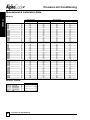
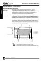
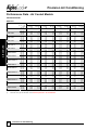
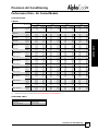
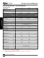
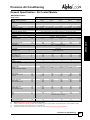
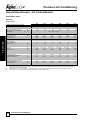
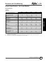
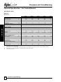
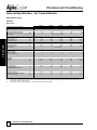
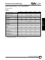
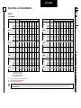
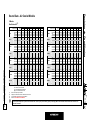
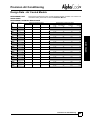
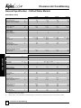
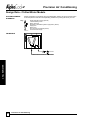
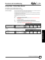
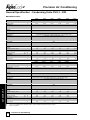
Precision Air Conditioning
-V
Design Data - Air Cooled Models
REFRIGERANT
CHARGING GUIDE
The following information can be used to estimate the refrigerant quantity required in a
split system installation.
Unit Refrigerant Charge
(Kg/Circuit)
The following table shows the refrigerant charge / circuit for the indoor and outdoor units.
Indoor Unit (IR)
V 9 - 16
V 19 - 23
V 25
V 23D - 31D
V 35
V 41D & 50D
V 45D & 55D
V 65D - 80D
V 90D
AIR COOLED
(1)
Liquid Line Refrigerant
Charge (kg/m)
A&X
A&X
A&X
A&X
A&X
A&X
A&X
A&X
A&X
Condenser (OR)
C 11 - 15
C 20
C 25
C 35 - 45
CS 50
kg/Circuit
2.1
2.3
3.1
6.1
10.0
Condensing
Unit (OR)
CUS 3 - 4
CUS 5 - 6
CUS 6.5 - 7.5
CUS 8.5 - 12
CUS 30D
kg/Circuit (1)
1.5
2.4
3.6
4.8
9.0
CUS3-4 models are delivered PRECHARGED with refrigerant.
The following table shows the refrigerant charge / metre for the liquid line, using R407C
and assuming liquid line temperature of 40°C.
Liquid Line (m)
3/8”
1/2”
5/8”
3/4”
7/8”
1 1/8”
IMPORTANT
kg/Circuit
2.1
3.8
4.6
2.7
4.1
4.1
6.1
6.7
8.0
kg/m
0.05
0.10
0.16
0.24
0.33
0.58
The pipe sizes/refrigerant charges quoted are for guidance only. It is the responsibility of
the installing contractor/site engineer to check the pipe sizes/refrigerant charge are correct
for each system installation and application.
Split systems may require additional oil which should be added to the low side of
each compressor.
Design should be in accordance with accepted refrigeration practice to ensure good oil
return to the compressor(s) under all normal operating conditions.
46
Precision Air Conditioning
Technical Manual : 6258867 F 07/2012