1
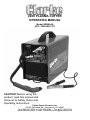
220V PLASMA CUTTER
OPERATING MANUAL
Model WE6494A
UPC: 052249010173
CAUTION: Before using this
product, read this manual and
follow all its Safety Rules and
Operating Instructions.
Clarke Power Products Inc.
28740 Glenwood Rd., Perrysburg, OH 43551
Tel # 800-227-9603 or (419) 930-2299 - Fax # 877-354-0740
www.clarkeusa.com - E-mail: [email protected]
TABLE OF CONTENTS
Warranty ..............................................2
Safety Summary ..................................3
Safety Information ..............................3
Shock Hazards ..................................4
Flash Hazards ....................................4
Fire Hazards ......................................5
Plasma Arc Hazards ..........................6
Fume Hazards....................................6
Additional Safety Information ............7
Plasma Cutter Specifications ............8
Description ........................................8
Operating Characteristics ..................8
Duty Cycle........................................8
Internal Thermal Protection..............8
Pneumatic Protection ......................8
Electric Shock Protection ................8
Know Your Plasma Cutter ..................9
Plasma Cutter Installation ..................10
Site Selection ....................................10
Power Source Connection ................10
Power Requirements........................10
Connect to Power Source ................10
Extension Cords ..............................10
Assembling the Plasma Cutter ..........10
Unpacking the Plasma Cutter ..........11
Packing List......................................11
Operation ............................................11
Connecting the Air Supply..................11
Connecting the Ground Clamp to the
Workpiece ..........................................12
Powering Up the Unit ........................12
Principles of Plasma Cutting ..............12
Learning to Plasma Cut......................13
Holding the Torch ............................13
Position the Torch to the Workpiece 13
Cutting ................................................13
Piercing ..............................................14
Recommended Cutting Speeds ........14
Maintenance ........................................15
Draining Condensation ......................15
Replacing the Nozzle ........................15
Replacing the Electrode ....................16
Replacing the Swirl Ring ....................16
Replacing the Nozzle Cap..................16
Troubleshooting..................................16
Wiring Diagram....................................18
Parts List ..............................................19
WARRANTY
This product has a one year warranty covering any manufacturing defects. Even though we have strict
quality control during our manufacturing process, sometimes a product gets shipped that does not meet
our specifications. If you have a product that does not work correctly within 30 days of your purchase, take
the product and the original receipt to the store for credit or replacement. If you have a product that does
not work correctly when it is more than 30 days after your purchase, then you must return the product to
the following address—postage or UPS paid. After 30 days, please do not return the product to the store.
This will only delay the repair process. Consumable items such as motor brushes, blades, bulbs etc. are
not covered under warranty.
Before returning any product, you must contact Clarke Power Products at
1-800-227-9603 to acquire a Return Authorization Number.
When sending your product you must include:
1. A copy of the dated store receipt showing the original purchase,
2. Name of store and town where product was purchased,
3. Your full name, street address and telephone number.
Please ship to:
Clarke Power Products Inc., 28740 Glenwood Road, Perrysburg, OH 43551 ATTN: Warranty Return
We will examine the product. If the problem is due to a manufacturing defect, we will repair or replace the
product at no charge and return it to you postage or UPS paid. If the problem is due to misuse, abuse, the
product has been modified or out of warranty, we will contact you with a repair estimate and ask for a credit card number for payment. After the product has been repaired, it will be returned postage or UPS paid.
2
SAFETY SUMMARY
TABLE OF CONTENTS
Every craftsman respects the tools with
which they work. They know that the tools
represent years of constantly improved
designs and developments. The true
craftsman also knows that tools are
dangerous if misused or abused.
Note:
• The following safety alert symbols identify
important safety messages in this manual.
• When you see one of the symbols shown
here, be alert to the possibility of personal
injury and carefully read the message that
follows.
This symbol indicates that the
possibility of electric shock hazard
exists during the operation of the
step(s) that follow.
Reading this operator’s manual before using
the plasma cutter will enable you to do a better, safer job. Learn the plasma cutter’s
applications and limitations as well as the
specific potential hazards peculiar to plasma
cutting.
This symbol indicates that the
possibility of fire hazard exists
during the operation of the step(s)
that follow.
IMPORTANT SAFETY
INFORMATION
This symbol indicates that the
helmet must be worn during the
step(s) that follow to protect
against eye damage and burns
due to flash hazard.
The following safety information is provided
as guidelines to help you operate your new
plasma cutter under the safest possible conditions. Any equipment that uses electrical
power can be potentially dangerous to use
when safety or safe handling instructions are
not known or not followed. The following
safety information is provided to give the
user the information necessary for safe use
and operation.
This symbol indicates that the
possibility of toxic gas hazard
exists during operation of the
step(s) that follow.
This symbol indicates that the
possibility of being burned by hot
slag exists during operation of the
step(s) that follow.
A procedure step preceded by a
WARNING is an indication that the next step
contains a procedure that might be injurious
to a person if proper safety precautions are
not heeded.
This symbol indicates that the eye
protection should be worn to
protect against flying debris in
the following step(s).
A procedure step preceded by a CAUTION
is an indication that the next step contains a
procedure that might damage the equipment
being used.
A NOTE may be used before or after a
procedure step to highlight or explain
something in that step.
READ ALL SAFETY INSTRUCTIONS
CAREFULLY before attempting to install,
operate, or service this plasma cutter. Failure
to comply with these instructions could result
in personal injury and/or property damage.
RETAIN THESE INSTRUCTIONS FOR
FUTURE REFERENCE.
•
This symbol indicates that the
possibility of injury or death exists
due to improper handling and
maintenance of compressed gas
cylinders or regulators.
Published standards on safety are
available. They are listed in ADDITIONAL
SAFETY INFORMATION at the end of
this SAFETY SUMMARY.
The National Electrical Code, Occupation
Safety and Health Act regulations, local
industrial codes and local inspection
requirements also provide a basis for
equipment installation, use, and service.
3
SHOCK HAZARDS
WARNING
ELECTRIC SHOCK CAN KILL! To reduce
the risk of death or serious injury from shock,
read, understand, and follow the following
safety instructions. In addition, make certain
that anyone else who uses this equipment,
or who is a bystander in the operating area
understands and follows these safety instructions as well.
• IMPORTANT! TO REDUCE THE RISK
OF DEATH, INJURY, OR PROPERTY
DAMAGE, DO NOT ATTEMPT
OPERATION of this equipment until you
have read and understand the following
safety summary.
• Do not, in any manner, come into
physical contact with any part of the cutting current circuit. The cutting current
circuit includes:
a. the work piece or any conductive
material in contact with it,
b. the ground clamp,
c. the torch,
d. any metal parts on the torch.
• Do not operate in a damp area or come
in contact with a moist or wet surface.
• Do not attempt to operate if any part of
clothing or body is wet.
• Do not allow the equipment to come in
contact with water or moisture.
• Do not drag cables, cutting torch, or
power cord through or allow them to
come into contact with water or moisture.
• Do not touch unit or attempt to turn unit on
or off if any part of the body or clothing is
moist or if you are in physical contact with
water or moisture.
• Do not attempt to plug the unit into the
power source if any part of body or clothing is moist, or if you are in physical
contact with water or moisture.
• Do not connect ground clamp to or cut on
electrical conduit.
• Do not alter power cord or power cord
plug in any way.
• Do not attempt to plug the unit
into the power source if the ground prong
on power cord plug is bent over, broken
off, or missing.
4
•
•
•
•
•
•
Do not allow the unit to be connected to
the power source or attempt to operate if
the unit, cables, work area, or power cord
are exposed to any form of atmospheric
precipitation, or salt water spray.
Do not carry coiled cables around shoulders, or any other part of the body, when
they are plugged into the unit.
Do not modify any wiring, ground
connections, switches, or fuses in this
equipment.
Wear welding gloves to help insulate
hands from cutting circuit.
Keep all liquid containers far enough
away from the unit and work area so that
if spilled, the liquid can not possibly come
in contact with any part of the unit or electrical circuit.
Replace any cracked or damaged parts
that are insulated or act as
insulators such as cables, power cord, or
electrode holder IMMEDIATELY.
.
FLASH HAZARDS
WARNING
ARC RAYS CAN INJURE EYES AND
BURN SKIN! To reduce the risk of injury
from arc rays, read, understand, and follow
the following safety instructions. In addition,
make certain that anyone else that uses this
equipment, or is a bystander in the work
area understands and follows these safety
instructions as well. Headshields and filter
should conform to ANSI Z87.1 standards.
•
•
•
Do not look at an electric arc without proper
protection. A cutting arc is extremely bright
and intense and, with inadequate or no eye
protection, the retina can be burned, leaving a permanent dark spot in the field of
vision. A shield or helmet with a number 8
shade filter lens (minimum) must be used.
Do not strike an arc until all bystanders
and the operator have protective shields
and/or helmets in place.
Do not wear a cracked or broken
helmet and replace any cracked or
broken filter lenses IMMEDIATELY.
•
•
•
•
To prevent an arc flash from being created on contact do not allow the uninsulated portion of the cutting torch to touch
the ground clamp or grounded work.
Provide bystanders with shields or
helmets fitted with a #8 shade filter lens.
Wear protective clothing. The intense
light of the cutting arc can burn the skin
in much the same way as the sun, even
through light-weight clothing. Wear dark
clothing of heavy material. The shirt worn
should be long sleeved and the collar
kept buttoned to protect chest and neck.
Protect against REFLECTED ARC RAYS.
Arc rays can be reflected off shiny surfaces
such as a glossy painted surface,
aluminum, stainless steel, and glass. It is
possible for your eyes to be injured by
reflected arc rays even when wearing a
protective helmet or shield. If working with
a reflective surface behind you, arc rays
can bounce off the surface, then off the filter lens on the inside of your helmet or
shield, then into your eyes. If a reflective
background exists in your work area, either
remove it or cover it with something nonflammable and non-reflective. Reflective
arc rays can also cause skin burn in addition to eye injury.
FIRE HAZARDS
WARNING
FIRE OR EXPLOSION CAN CAUSE
DEATH, INJURY, AND PROPERTY DAMAGE! To reduce the risk of death, injury, or
property damage from fire or explosion, read,
understand, and follow the following safety
instructions. In addition, make certain that
anyone else that uses this equipment, or is a
bystander in the work area, understands and
follows these safety instructions as well.
REMEMBER! Plasma arc cutting, by nature
produces sparks, hot spatter, molten metal
drops, hot slag, and hot metal parts that can
start fires, burn skin, and damage eyes.
•
Do not wear gloves or other clothing that
contains oil, grease, or other
flammable substances.
•
•
•
•
•
•
•
•
•
•
•
Do not wear flammable hair
preparations.
Do not work in an area until it is checked
and cleared of combustible and/or
flammable materials. BE AWARE that
sparks and slag can fly 35 feet and can
pass through small cracks and openings.
If work and combustibles cannot be
separated by a minimum of 35 feet,
protect against ignition with suitable,
snug-fitting, fire resistant, covers or
shields.
Do not plasma cut on walls until checking
for and removing combustibles touching
the other side of the walls.
Do not weld, cut, or perform other such
work on used barrels, drums, tanks, or
other containers that had contained a
flammable or toxic substance. The
techniques for removing flammable substance and vapors, to make a used
container safe for welding or cutting, are
quite complex and require special
education and training.
Do not strike an arc on a compressed
gas or air cylinder or other pressure
vessel. Doing so will create a brittle area
that can result in a violent rupture
immediately or at a later time as a result
of rough handling.
Do not weld or cut in an area where the
air may contain flammable dust (such as
grain dust), gas, or liquid vapors (such as
gasoline).
Do not handle hot metal, such as the work
piece or electrode stubs, with bare hands.
Wear leather gloves, heavy long sleeve
shirt, cuffless trousers, high-topped
shoes, helmet, and cap. As necessary,
use additional protective clothing such as
leather jacket or sleeves, fire resistant
leggings, or apron. Hot sparks or metal
can lodge in rolled up sleeves, trouser
cuffs, or pockets. Sleeves and collars
should be kept buttoned and pockets
eliminated from the shirt front.
Have fire extinguisher equipment handy
for immediate use! A portable chemical
fire extinguisher, type ABC, is
recommended.
Wear ear plugs when working overhead
to prevent spatter or slag from falling
into ear.
Make sure work area has a good, solid,
5
•
•
safe floor, preferably concrete or masonry, not tiled, carpeted, or made of any
other flammable material.
Protect flammable walls, ceilings,
and floors with heat resistant covers
or shields.
Check work area to make sure it is free
of sparks, glowing metal or
slag, and flames before leaving the
work area.
•
•
PLASMA ARC HAZARDS
WARNING
THE HEAT FROM THE PLASMA ARC CAN
CAUSE SERIOUS BURNS. THE FORCE
OF THE ARC ADDS GREATLY TO THE
BURN HAZARD. THE INTENSELY HOT
AND POWERFUL ARC CAN QUICKLY CUT
THROUGH GLOVES AND TISSUE.
•
•
•
•
•
•
Keep away from the torch tip.
Do not grip material near the cutting path.
The pilot arc can cause burns - keep
away from torch tip when trigger is
pressed.
Wear proper flame retardant clothing covering all exposed body areas.
Point torch away from your body and
toward work when pressing the
torch trigger
Turn off power source and disconnect
input power before disassembling torch
or changing torch parts.
FUME HAZARDS
WARNING
FUMES, GASSES, AND VAPORS CAN
CAUSE DISCOMFORT, ILLNESS, AND
DEATH! To reduce the risk of discomfort,
illness, or death, read, understand, and
follow the following safety instructions. In
addition, make certain that anyone else that
uses this equipment or is a bystander in the
work area, understands and follows these
safety instructions as well.
6
•
•
•
•
Do not work in an area until it is checked
for adequate ventilation as described in
ANSI standard #Z49.1. If ventilation is
not adequate to exchange all fumes and
gasses generated during the cutting
process with fresh air, do not plasma cut
unless the operator and all bystanders
are wearing air-supplied respirators.
Do not heat metals coated with, or that
contain, materials that produce toxic
fumes (such as galvanized steel), unless
the coating is removed. Make certain the
area is well ventilated, and the operator
and all bystanders are wearing air-supplied respirators.
Do not weld, cut, or heat lead, zinc,
cadmium, mercury, beryllium, or similar
metals without seeking professional
advice and inspection of the ventilation of
the work area. These metals produce
EXTREMELY TOXIC fumes which can
cause discomfort, illness, and death.
Do not weld or cut in areas that are near
chlorinated solvents. Vapors from
chlorinated hydrocarbons, such as
trichloroethylene and perchloroethylene,
can be decomposed by the heat of an
electric arc or its ultraviolet radiation.
These actions can cause PHOSGENE, a
HIGHLY TOXIC gas to form, along with
other lung and eye-irritating gasses. Do
not weld or cut where these solvent
vapors can be drawn into the work area
or where the ultraviolet radiation can
penetrate to areas containing even very
small amounts of these vapors.
Do not weld or cut in a confined area
unless it is being ventilated or the operator (and anyone else in the area) is wearing an air-supplied respirator.
Stop working if you develop momentary
eye, nose, or throat irritation as this
indicates inadequate ventilation. Stop
work and take necessary steps to
improve ventilation in the work area. Do
not resume work if physical discomfort
persists.
ADDITIONAL SAFETY
INFORMATION
For additional information concerning
welding and cutting safety, refer to the following standards and comply with them as
applicable.
•
•
•
ANSI Standard Z49.1 – SAFETY IN
WELDING AND CUTTING – obtainable
from the American Welding Society, 550
NW Le Jeune Road, Miami, FL 33126
Telephone (800) 443-9353,
Fax (305) 443-7559 – www.amweld.org
or www.aws.org
ANSI Standard Z87.1 – SAFE PRACTICE FOR OCCUPATION AND
EDUCATIONAL EYE AND FACE
PROTECTION – obtainable from the
American National Standards Institute,
11 West 42nd St., New York, NY 10036
Telephone (212) 642-4900,
Fax (212) 398-0023 – www.ansi.org
NFPA Standard 51B – CUTTING AND
WELDING PROCESS – obtainable from
the National Fire Protection Association,
1 Batterymarch Park, P.O. Box 9101,
Quincy, MA 02269-9101
Telephone (617) 770-3000
Fax (617) 770-0700 – www.nfpa.org
•
•
•
OSHA Standard 29 CFR, Part 1910,
Subpart Q., WELDING, CUTTING AND
BRAZING – obtainable from your state
OSHA office or U.S. Dept. of Labor
OSHA, Office of Public Affairs, Room
N3647, 200 Constitution Ave.,
Washington, DC 20210 – www.osha.gov
CSA Standard W117.2 – Code for
SAFETY IN WELDING AND CUTTING. –
obtainable from Canadian Standards
Association, 178 Rexdale Blvd.,
Etobicoke, Ontario M9W 1R3 –
www.csa.ca
American Welding Society Standard
A6.0. WELDING AND CUTTING
CONTAINERS WHICH HAVE HELD
COMBUSTIBLES. – obtainable from the
American Welding Society, 550 NW Le
Jeune Road, Miami, FL 33126
Telephone (800) 443-9353,
Fax (305) 443-7559 – www.amweld.org
or www.aws.org
7
DESCRIPTION
PLASMA CUTTER SPECIFICATIONS
Your new Plasma Cutter is designed as a
clean, distortion free means of cutting
through metal, up to 3/16 inch thick.The
plasma cutter power generator consists of a
transformer, a rectifying unit, and a PC
Board. The PC Board controls the unit safeguards and governs the work cycles of the
various components which make up the unit,
such as the solenoid valve, the power contactor, etc. Table 1 lists your Plasma Cutter
specifications.
Table 1. Plasma Cutter Specifications
Primary (input) volts
220 Vac
Primary (input) Amps
25
Phase
Single
Frequency
60Hz
Secondary (output) volts
100
Secondary (CSA output) amps
25
Open Circuit Volts (Max.)
300 Vdc
Duty Cycle Rating
15%
PLASMA CUTTER OPERATING
CHARACTERISTICS
DUTY CYCLE
The duty cycle rating of a plasma cutter
defines how long the operator can cut and
how long the unit must be rested and cooled.
Duty cycle is expressed as a percentage of
10 minutes and represents the maximum
cutting time allowed. The balance of the 10minute cycle is required for cooling.
This plasma cutter has a duty cycle rating of
15% at the rated output. This means that you
can cut for 1.5 minutes out of 10 with the
remaining 8.5 minutes required for cooling.
8
INTERNAL THERMAL PROTECTION
CAUTION
Do not constantly exceed the duty cycle or
damage to the unit can result.
If you exceed the duty cycle of the plasma
cutter, an internal thermal protector will open,
shutting off all functions except the cooling
fan. If this happens, DO NOT SHUT OFF
THE UNIT. Leave the unit turned on with the
fan running. After cooling, the thermal protector will automatically reset and the unit will
function normally again. However you should
wait at least ten minutes after the thermal
protector opens before resuming work. You
must do this even if the thermal protector
resets itself before the ten minutes is up or
you may experience less than specified duty
cycle performance.
PNEUMATIC PROTECTION
A pneumatic device prevents damage to the
torch due to switching on with either no air
supply or low air pressure. An amber light on
the front panel lights up when the pneumatic
device intervenes. (See Figure 1)
ELECTRIC SHOCK PROTECTION
An electric shock protection device prevents
the operator from coming into contact with
electrically live parts of the torch (such as the
electrode, etc.). This consists of a safety
device, built into the body of the torch, which
breaks the main power circuit when the end
part of the torch is removed to replace the
electrode or the nozzle.
Note: When the electrical protection device
is activated, the unit is prevented from
operating.
KNOW YOUR PLASMA CUTTER
tion at the ground clamp will waste power
and heat. Scrape away dirt, rust, scale, oil or
paint before attaching the ground clamp.
Ground Cable – The ground cable connects
the ground clamp to the internal workings of
the plasma cutter.
Cutting Torch and Cable – The cutting
torch controls the delivery of the plasma arc
to the material to be cut. Compressed air
and electricity is fed through the cable and
cutting torch when the trigger is pulled. An
electrode and cutting nozzle must be properly installed (as described later in this manual)
prior to cutting.
Figure 1. Model WE6494A Plasma Cutter
Handle – Rugged, top mounted handle
allows for easy transport of your plasma
cutter.
Power Indicator Lamp - This lamp will light
whenever Power Switch (on back of unit) is
turned to the ON position.
Pneumatic Protection Indicator Lamp This plasma cutter includes a pneumatic protection device, designed to prevent damage
to the unit when there is no air supply or low
air pressure on intake. Lamp will light when
pneumatic protection device intervenes.
Thermal Overload Protection Lamp - When
duty cycle has been exceeded an internal
thermal protector switch will open. This lamp
will light when thermal protection engages.
Power Cord – This is a standard 50 amp
220 volt power cord. (Make sure you are
using a properly grounded 220 Vac, 60Hz,
single phase, 25 amp power source.)
Ground Clamp – Attaching the ground
clamp to your workpiece “completes” the
electrical current circuit. You must attach the
ground clamp to the metal you are cutting. If
the ground clamp is not connected to the
metal workpiece you intend to cut, the plasma cutter will not have a completed circuit
and you will be unable to cut. A poor connec-
Power Switch – This switch turns the unit
ON and OFF. (Make sure the power switch is
in the OFF position before performing any
maintenance on the unit.)
Air Pressure Gauge - This gauge displays
the psi of air leaving the unit. To adjust the
air pressure, use the Air Pressure Regulator.
Air Pressure Regulator - Turn regulator
clockwise to increase air pressure, counterclockwise to decrease air pressure.
Air Inlet - Accepts threaded male coupling or
threaded male quick connector. Incoming air
should be regulated at 65 psi.
Water Trap - Check the water trap regularly.
Whenever the unit is not used for a week or
more, the compressed air should be disconnected completely. To drain condensation
turn the knurled nut on the bottom of the filter counter-clockwise.
9
PLASMA CUTTER INSTALLATION
SITE SELECTION
Select a clean, dry location with adequate
working space around all components.
The power supply is fan cooled by air flow
through the front and rear panels. This air
flow must not be obstructed. Provide at least
two feet of space in front of and behind the
unit to allow for free flow of air.
POWER SOURCE CONNECTION
POWER REQUIREMENTS
This plasma cutter is designed to operate on
a properly grounded 220 volt, 60Hz, singlephase alternating current (ac) power source
fused with a 25 amp time delayed fuse or
circuit breaker. It is recommended that a
qualified electrician verify the ACTUAL
VOLTAGE at the receptacle into which the
plasma cutter will be plugged and confirm
that the receptacle is properly fused and
grounded. The use of the proper circuit size
can eliminate nuisance circuit breaker
tripping when working.
DO NOT OPERATE THIS UNIT if the
ACTUAL power source voltage is less than
198 volts ac or greater than 240 volts ac.
Contact a qualified electrician if this problem
exists. Improper performance and/or damage
to the plasma cutter will result if operated on
inadequate or excessive power.
CONNECT TO POWER SOURCE
WARNING
High voltage danger from power source!
Consult a qualified electrician for proper
installation of receptacle at the power source.
This plasma cutter must be grounded while in
use to protect the operator from electrical
shock. If you are not sure if your outlet is properly grounded, have it checked by a qualified
electrician. Do not cut off the grounding prong
or alter the plug in any way and do not use
any adapters between the plasma cutter’s
power cord and the power source receptacle.
Make sure the POWER switch is OFF then
connect your plasma cutter’s power cord to a
properly grounded 220 Vac, 60 Hz, single
phase, 25 amp power source.
10
WIRING
The wires in the input cable of this machine
are colored in accordance with the following
code:
RED:
LIVE
BLACK: LIVE
GREEN & YELLOW: GROUND
Connect the input cable to a suitably fused
220Volt/1 Phase electrical supply.
This unit is wired at the factory for 220 Volt,
1 Phase, 60 Hz operation. Check the voltage
at the power supply before connecting to the
power supply.
WARNING: THIS MACHINE MUST BE
GROUNDED.
Note: If connecting the input cable to an
electrical plug, make sure that the plug is
rated for operation with this unit. Follow all
plug manufacturer’s instructions, making
sure that the live wires and the ground wire
are properly connected to the plug.
EXTENSION CORDS
For optimum performance, an extension cord
should not be used unless absolutely necessary. If necessary, care must be taken in
selecting an extension cord appropriate for
use with your specific plasma cutter.
Select a properly grounded extension cord
that will mate directly with the power source
receptacle and the plasma cutter power cord
without the use of adapters. Make certain
that the extension cord is properly wired and
in good electrical condition.
Extension cords must be a #12 gauge cord
at the smallest. Do not use an extension
cord over 25 ft. in length.
ASSEMBLING THE PLASMA CUTTER
The following procedures describe the
process required to assemble, install, maintain, and prepare to work with your new plasma cutter.
UNPACKING THE PLASMA CUTTER
1. Remove any cartons or bags containing
parts/accessories.
2. Open the cartons or bags packed with your
plasma cutter and inspect their contents for
damage.
3. Lay out the parts and compare them to
the packing list in Table 2 to familiarize
yourself with the parts and what they are
called. This will help you when reading
the manual.
OPERATION
CONNECTING THE AIR SUPPLY
1. Before attaching the air supply to the
plasma cutter, pull out the air pressure
regulator knob and turn it fully counterclockwise. This will set the regulator to its
lowest pressure. (see Figure 2)
PACKING LIST
Figure 2
Table 2 contains a list of the items you will
find packed in the carton.
Table 2. Packing List
ITEM
Plasma Cutter
Parts Bag
Swirl Ring (1 is installed)
Electrodes (1 is installed)
Nozzles (1 is installed)
1/4" Male Coupler
Manual, Instruction
QTY.
1
1
2
2
2
1
1
Lowering Regulator
Pressure
2. Feed the 1/4 inch male air coupler
threads into the plasma cutter’s air inlet.
Firmly tighten in place with wrench.
Note: The use of a sealant tape is recommended on the threads of the air coupler to
prevent air leakage.
3. Attach air hose (with quick connect coupler) to 1/4 inch male air coupler. Make
sure air hose is fully seated on coupler
before letting go. (See Figure 3)
Air Inlet
1/4 inch Male
Fitting Air Coupler
Air Hose with
Quick Connect
Figure 3. Connecting the Air Supply
11
4. Turn on the air supply. Make sure that
the air supply pressure is at least 90psi.
(90 -120 psi is ideal)
5. Pull out the air pressure regulator knob
and set a pressure of 65 psi by turning
the knob clockwise.
6. When the pressure on the air regulator
gauge is set to 65 psi, lock the knob in
position by firmly pushing down on it.
(See Figure 4)
indicating that the plasma cutter is supplied with power.
4. Holding the torch away from yourself and
others in the work area, pull the torch
trigger and verify that the pressure indicated on the pressure gauge is at
approximately 65 psi.
Note: This Plasma Cutter has an internal
safety feature which prevents accidental
arcs. To light the pilot arc, press the torch
button; release it and press it again within 3
seconds The pilot arc will go out after
approximately 2-3 seconds if cutting has not
begun. To relight the pilot arc, simply repeat
the steps above. Avoid unnecessary lighting
of the pilot arc to prevent consumption of the
electrode and nozzle.
PRINCIPLES OF PLASMA CUTTING
Figure 4
Adjusting Regulator
Pressure
CONNECTING THE GROUND CLAMP
TO THE WORKPIECE
1. Remove any dirt, grease, scale, rust,
paint, etc. from the area of the workpiece
where the ground clamp is to be connected.
2. The ground clamp should be connected
to the workpiece as close to the area
being cut as possible. Make sure when
connecting the ground clamp that neither
the ground clamp or the ground cable will
intersect the intended cut line.
3. Fasten the ground clamp to the workpiece. Make certain the ground clamp is
securely fastened to the workpiece so
that it will not be likely to come loose during the plasma cutting operation.
POWERING UP THE UNIT
1. Plug power cord into properly grounded
220VAC, 60Hz, single phase power
source.
2. Switch the unit ON, using the main power
switch on the rear panel of the plasma
cutter. A hissing of air will be apparent for
a short period as the system is charged
and the water trap drain valve closes.
3. Make sure that the Power Indicator Lamp
on the front panel of the machine is on,
12
Plasma cutting is a fast, clean and distortion free means of cutting through all types of
metal from mild and stainless steels to aluminum, brass and copper.
The process relies upon the chemical
reaction of air when subjected to very high
temperatures. The air is ionized, leaving the
atoms positively charged. In the ionized
state, the air is electrically conductive and
called “plasma.”
A standing electric arc is created to
achieve the very high temperature required
to create plasma. By forcing the plasma
through a small nozzle, the arc is constricted
and its temperature is increased to over
36,000 degrees fahrenheit and concentrated
into a very small area.
When the plasma is directed at a conductive material (which is connected to the
ground clamp of the plasma cutter) the arc is
transferred through the plasma to the material. The high energy of the arc melts the
material. The melted metal material is simultaneously forced out of the cut area by the
air flow. As this glowing metal is removed
from the path of the plasma arc, the result is
a fast, clean cut.
The standing arc has to be created by
producing an ionized path in the air. This is
achieved by applying a very high voltage, at
high frequency, between the electrode and
the tip/work, causing a high frequency spark.
The main arc will ignite as soon as the tip
and nozzle are ionized.
Whether you have used a plasma cutter
before or not, it is important that you become
familiar with your new plasma cutter. We
strongly recommend that you practice with
your new plasma cutter on scrap metal trying
different base metals, base metal thicknesses,
and cutting positions. By doing this you will
gain a feel for how changes in these variables
affect the cutting process.
Of course, if you have not used a plasma
cutter before, you will need to develop proper cutting skills and techniques as well.
The self-taught operator learns through a
process of trial and error. The best way to
teach yourself how to plasma cut is with
short periods of practice at regular intervals.
All practice cuts should be done on scrap
metal that can be discarded. Do not attempt
to make any cuts on valuable equipment
until you have satisfied yourself that your
practice cuts are of good appearance and
free from major faults.
technique that feels most comfortable and
allows good control and movement.
Position the Torch to the Workpiece
The plasma torch nozzle should be perpendicular to the workpiece. Excessive angling of
the torch can cause the plasma arc to cut
into the side wall of the nozzle, resulting in
damage to the torch components. It is important to keep the cutting torch at the proper
distance from the material being cut. This
distance may vary slightly, depending upon
the type of material and thickness of material
being cut, but a general rule of thumb is to
keep the nozzle approximately 1/16 to 1/8
inch from the material being cut.
See Figure 6 for proper torch position.
Figure 6. Torch Position
CUTTING
Figure 5. Principles of Plasma Cutting
LEARNING TO PLASMA CUT
Holding the Torch
The best way to hold the cutting torch is the
way that feels most comfortable to you. The
torch can be comfortably held in one hand,
or steadied using two hands. Choose the
A “cutting” operation is generally defined as
one where the penetration begins at an
existing edge of the workpiece. Whether this
edge is an outer edge or a previously made
hole somewhere in the workpiece is irrelevant. Cutting operations require a slightly different technique than Piercing operations
(described in next section).
1. Position your index finger on the trigger.
2. Hold the torch with the nozzle orifice
directly over the edge of the workpiece.
Note: Arc stretching can occur at the beginning and end of the cut if the arc has to
"stretch" (deviate from a straight, perpendicular path) to find metal. Arc stretching can
cause the arc to cut into the side wall of the
nozzle.
13
WARNING
WARNING
EXPOSURE TO A PLASMA ARC IS
EXTREMELY HARMFUL TO THE EYES
AND SKIN! Prolonged exposure to the plasma arc can cause blindness and burns.
Never strike an arc or begin cutting until you
are adequately protected. Wear flameproof
welding gloves, a heavy long sleeved shirt,
cuffless trousers, high topped shoes and a
welding helmet.
3. With the torch in the starting position pull
the trigger and release, and then immediately pull the trigger again and hold. The
pilot arc will come on until the cutting arc
starts. (Once on, the main arc stays on
as long as the trigger is held down,
unless the torch is withdrawn from the
work or the cutting motion is too slow.)
4. With the torch nozzle perpendicular to
the workpiece, pull (or push) the torch
across the area to be cut at a moderate,
steady pace.
5. To shut the torch off, simply release the
trigger.
Note: When the trigger is released and the
arc is extinguished, compressed air will continue to flow for a short period, in order to
cool the torch. DO NOT switch off the
machine until the air has stopped flowing or
damage to the torch may occur.
EXPOSURE TO A PLASMA ARC IS
EXTREMELY HARMFUL TO THE EYES
AND SKIN! Prolonged exposure to the plasma arc can cause blindness and burns.
Never strike an arc or begin cutting until you
are adequately protected. Wear flameproof
welding gloves, a heavy long sleeved shirt,
cuffless trousers, high topped shoes and a
welding helmet.
3. Pull the trigger and release, and then
immediately pull the trigger again and hold.
4. Lower the tip of the torch to within 1/8
inch of the workpiece or until the main
cutting arc transfers to the workpiece and
sparks start.
4. If you intend only to pierce the workpiece,
release the trigger when the plasma
stream has penetrated the material.
5. For extended cuts, proceed to pull (or
push) the torch across the area to be cut
at a moderate, steady pace.
6. To shut the torch off, simply release the
trigger.
Note: When the trigger is released and the
arc is extinguished, compressed air will continue to flow for a short period, in order to cool
the torch. DO NOT switch off the machine
until the air has stopped flowing or damage to
the torch may occur.
A “piercing” operation is defined as one
where the plasma arc creates a new penetration in a workpiece. Unlike a Cutting operation, this means that there is no existing
edge to begin work from. The arc is forced
through the workpiece, thereby creating a
new “edge.” After the initial penetration has
been made, a piercing operation is treated in
the same manner as a cutting operation.
1. Position your index finger on the trigger.
2. Hold the torch approximately 1/4 inch
above the workpiece, with the nozzle orifice directly over the spot on the workpiece where piercing is desired. It may
be necessary to angle the torch VERY
slightly while at this point to ensure that
sparks and/or spatter will not rebound
into the nozzle cap and nozzle.
The cutting speed necessary to produce
good, clean cuts depends on several variables: Material Type, Material Thickness,
Distance from the material to be cut,
Accuracy of the operator, Line voltage fluctuations and a host of others. Table 3 offers
some general suggestions for cutting speeds,
assuming that all conditions are ideal. Actual
results may vary and it is recommended that
you practice your cuts before beginning work
on any valuable materials.
Inches
Material
Gauge
per minute
Stainless Steel
20
60
Galvanized Steel
18
60
Aluminum
16
20
Carbon Steel
10
10
Table 3. Cutting Speeds
PIERCING
14
RECOMMENDED CUTTING SPEEDS
MAINTENANCE
This plasma cutter has been engineered to
give many years of trouble free service providing that a few very simple steps are taken
to properly maintain it.
1. Keep the unit clean and free of dust.
Periodically use dry, compressed air to
clean dust deposits from face plate and
vents
2. Check the water trap regularly. Drain
condensation before every use.
3. Keep the torch components free of slag
at all times. A clogged nozzle or electrode will not allow proper airflow and
may damage the torch.
4. Keep consumables in good working condition. Replace consumables as needed.
5. Form a regular habit of checking electrical cable and torch cable. If any damage
is apparent, the cable should be replaced
immediately.
DRAINING CONDENSATION
Keeping a clean, dry air flow to your plasma
cutter is essential for reliable, trouble free
service. By regularly draining condensation
from the water trap you will promote a longer
life for consumable parts.
Note: If your plasma cutter will not be used
for extended periods of time, disconnect it
from the air supply.
1. Slowly turn the knurled drain valve on the
bottom of the water trap housing counterclockwise (as viewed from bottom of unit)
until it is fully open.
2. Allow all condensation to drain.
3. Retighten drain valve.
REPLACING THE NOZZLE
During the cutting process, the parts on the
end of the torch are slowly consumed. To
prevent premature consumption of some
torch parts and to prevent damage to the
torch itself, it is necessary to replace the
consumable parts in a timely manner.
If your cuts begin to appear jagged, or the
cutting arc becomes difficult to maintain, it
may be necessary to change the nozzle. A
quick visual inspection will reveal whether a
nozzle is worn. The hole in the tip of a good
nozzle is round. Once the hole takes on an
elongated, or elliptical shape it is necessary
to replace the nozzle. (See Figure 8)
Figure 8. Nozzles
1. After allowing torch to cool, remove the
nozzle cap from the torch by turning it
counterclockwise.
2. Remove the worn nozzle.
3. Place new nozzle onto electrode.
4. Replace nozzle cap by firmly turning it
clockwise onto torch assembly (refer to
Figure 9).
Swirl
Ring
Electrode
Nozzle
Drain Valve
Figure 7. Draining Condensation
Nozzle Cap
Figure 9. Consumable Parts
15
REPLACING THE ELECTRODE
If your arc begins to lose power (i.e., will not
cut through workpiece any longer), or the
cutting arc becomes difficult to maintain, it
may be necessary to change the electrode.
A quick visual inspection will reveal whether
an electrode is worn. A worn electrode is
characterized by a crater shaped tip. Once
this crater reaches 1.5 - 2 millimeters in
depth, replacement is necessary.
(See Figure 10)
REPLACING THE SWIRL RING
The swirl ring has an average life expectancy of about 3 - 4 cutting hours. It needs to be
replaced when cracks, chips, or burn spots
begin to appear.
1. Remove the nozzle cap from the torch by
turning it counterclockwise.
2. Remove the nozzle.
3. Slide the worn swirl ring off of the torch.
4. Install the new swirl ring by sliding it into
place on the torch.
5. Place nozzle onto electrode.
6. Replace nozzle cap by firmly turning it
clockwise onto torch assembly (refer to
Figure 9).
REPLACING THE NOZZLE CAP
Figure 10. Electrodes
1. Remove the nozzle cap from the torch by
turning it counterclockwise.
2. Remove the nozzle.
3. Using a wrench, unscrew the worn electrode from the torch.
4. Install the new electrode by firmly tightening it in place. Only tighten electrode to
the point that it is fully seated in the
torch. Do not over-tighten.
5. Place nozzle onto electrode.
6. Replace nozzle cap by firmly turning it
clockwise onto torch assembly (refer to
Figure 9).
16
The nozzle cap should be replaced if it
develops cracks or burn through holes.
Always inspect the swirl ring when replacing
the nozzle cap and replace both if necessary.
To replace the nozzle cap, simply unscrew
the old one and replace with new.
TROUBLESHOOTING
The following TROUBLESHOOTING table is
a guide to help resolve some of the more
common problems that could be encountered. Use it to help you determine a possible remedy when you are having a problem
with your plasma cutter. This table does not
provide all possible solutions, only those
possibilities considered to be common faults.
The table consists of a TROUBLE or symptom, a POSSIBLE CAUSE for the symptom,
and a POSSIBLE REMEDY for that
symptom.
TROUBLESHOOTING
17
PLASMA CUTTER MODEL WE6494A WIRING DIAGRAM
18
PLASMA CUTTER MODEL WE6494A PARTS LIST
19
PLASMA CUTTER MODEL WE6494A PARTS DIAGRAM
20
PLASMA CUTTER MODEL WE6494A TORCH PARTS LIST
21
NOTES:
NOTES:
220V PLASMA CUTTER
OPERATING MANUAL
Model WE6494A
WE6494A-M001 1204